RU2425784C1 - Clamping unit of clip mechanism - Google Patents
Clamping unit of clip mechanism Download PDFInfo
- Publication number
- RU2425784C1 RU2425784C1 RU2009141994/21A RU2009141994A RU2425784C1 RU 2425784 C1 RU2425784 C1 RU 2425784C1 RU 2009141994/21 A RU2009141994/21 A RU 2009141994/21A RU 2009141994 A RU2009141994 A RU 2009141994A RU 2425784 C1 RU2425784 C1 RU 2425784C1
- Authority
- RU
- Russia
- Prior art keywords
- pinch plates
- pair
- plates
- pinch
- clamping plates
- Prior art date
Links
Images

Classifications
-
- A—HUMAN NECESSITIES
- A22—BUTCHERING; MEAT TREATMENT; PROCESSING POULTRY OR FISH
- A22C—PROCESSING MEAT, POULTRY, OR FISH
- A22C11/00—Sausage making ; Apparatus for handling or conveying sausage products during manufacture
- A22C11/10—Apparatus for twisting or linking sausages
- A22C11/104—Apparatus for twisting or linking sausages by means of shear or blade elements
- A22C11/105—The sheer or blade elements being displaceable parallel to the sausage string in order to create a narrow point free of meat
Landscapes
- Life Sciences & Earth Sciences (AREA)
- Engineering & Computer Science (AREA)
- Wood Science & Technology (AREA)
- Zoology (AREA)
- Food Science & Technology (AREA)
- Package Closures (AREA)
- Organic Low-Molecular-Weight Compounds And Preparation Thereof (AREA)
- Meat, Egg Or Seafood Products (AREA)
- Tubes (AREA)
Abstract
Description
Изобретение относится к пережимающему узлу клипсатора, в частности клипсатора для колбасных изделий, в соответствии с ограничительной частью пункта 1 формулы изобретения. В частности, изобретение относится к пережимающему узлу клипсатора, в частности клипсатора для колбасных изделий, содержащему, по меньшей мере, одну первую пару пережимающих пластин и расположенную параллельно ей вторую пару пережимающих пластин, причем пережимающие пластины установлены с возможностью реверсивного схождения для пережимания наполненной упаковочной оболочки с образованием свободного от продукта жгута. При этом первая пара состоит из двух зеркально-симметричных, по меньшей мере, приблизительно идентичных пережимающих пластин. Вторая пара содержит первые пережимающие пластины, по меньшей мере, приблизительно идентичные пережимающим пластинам первой пары пережимающих пластин, а также вторые более короткие пережимающие пластины.The invention relates to a pinching unit of a clipper, in particular a clipper for sausages, in accordance with the restrictive part of paragraph 1 of the claims. In particular, the invention relates to a pinching unit of a clipper, in particular a sausage clipper, comprising at least one first pair of pinch plates and a second pair of pinch plates located parallel to it, and pinch plates are mounted for reversible convergence for pinching a filled packaging shell with the formation of a product-free tourniquet. Moreover, the first pair consists of two mirror-symmetric, at least approximately identical pinch plates. The second pair comprises first pinch plates at least approximately identical to pinch plates of the first pair of pinch plates, as well as second shorter pinch plates.
С помощью клипсатора описанного выше рода, известного, например, из DE 2550042, запечатываются пакетные или рукавные упаковочные оболочки, обычно заполненные содержимым от жидкого до пастообразного или же (частично) гранулированного. Сначала во время этого процесса продукт помещается в упаковочную оболочку и в случае рукавной оболочки разделяется затем на порции (колбасы) посредством, например, пар пережимающих пластин пережимающего узла. Пары пережимающих пластин, расположенных с возможностью поворота вокруг общей оси в радиальном направлении или поперек направления подачи продукта, пережимают упаковочную оболочку и вытесняют находящийся в зоне пережима продукт в осевом направлении или в направлении его подачи. В зоне пережима образуется свободный от продукта жгут рукава. На нем на следующей операции посредством описанных выше, смыкающихся запечатывающих инструментов ставится одна или в случае двухклипсового устройства рядом друг с другом две скобки или клипсы. Если колбасное изделие для дальнейшей транспортировки или дальнейшей обработки должно подвешиваться, например, на коптильном стержне, то в одну из скобок вкладывается элемент для подвешивания, такой как шпагатная петля, и с помощью скобки крепится на жгуте оболочки. После запечатывания колбасного изделия за счет постановки скобок или клипс пары пережимающих пластин снова расходятся, что обеспечивает прохождение колбасного изделия.Using a clipper of the kind described above, known, for example, from DE 2550042, packet or sleeve packaging shells are usually sealed, usually filled with contents from liquid to pasty or (partially) granular. First, during this process, the product is placed in the packaging shell and, in the case of the tubular shell, is then divided into portions (sausages) by, for example, pairs of pinch plates of the pinch unit. Pairs of pinch plates arranged to rotate around a common axis in the radial direction or transverse to the product feed direction, compress the packaging shell and displace the product located in the pinch zone in the axial direction or in the feed direction. In the pinch zone, a sleeve-free bundle is formed. On it, in the next operation, by means of the closing sealing tools described above, one or two brackets or clips are placed next to each other in the case of a two-clip device. If the sausage product for further transportation or further processing should be suspended, for example, on a smoking rod, then an element for hanging, such as a twine loop, is inserted into one of the brackets and is attached to the sheath bundle using a bracket. After sealing the sausage product by setting brackets or clips, the pairs of pinch plates diverge again, which ensures the passage of the sausage product.
Из ЕР 1886573 известен клипсатор, пережимающий узел которого содержит пережимающие пластины, установленные с возможностью реверсивного схождения вдоль линейной направляющей для пережатия наполненной упаковочной оболочки.A clipper is known from EP 1886573, the pinching unit of which comprises pinching plates mounted with the possibility of reverse convergence along a linear guide for clamping the filled packaging shell.
На практике далее известно, что, прежде всего, при изготовлении колбасных изделий с элементом для подвешивания, которые непосредственно после изготовления должны автоматически размещаться посредством него в устройстве для подвешивания, нижние пережимающие пластины указывающей в направлении подачи продукта пары выполнены короче, чем остальные пережимающие пластины. Укорочение этих пережимающих пластин необходимо для того, чтобы освободить элемент для подвешивания, который находится в закрытой в остальном конструкции пережимающих пластин и удерживается скобкой между ними и улавливающим приспособлением в направлении подачи за пережимающими пластинами.In practice, it is further known that, first of all, in the manufacture of sausages with a hanging element, which immediately after production should be automatically placed by means of it in the hanging device, the lower pinch plates indicating the pairs in the product supply direction are made shorter than the other pinch plates. The shortening of these pinch plates is necessary in order to release the suspension element, which is located in the rest of the pinch plate structure and is held by a bracket between them and the catching device in the feed direction behind the pinch plates.
Эти известные клипсаторы имеют, однако, недостатки. Так, нельзя исключать того, что укороченные пережимающие пластины, прежде всего, в случае больших калибров колбасных изделий и/или восприимчивых упаковочных оболочек в процессе пережатия проникнут в упаковочную оболочку и образуют складку, которую нельзя будет охватить скобкой. Также нельзя исключить повреждения упаковочной оболочки.These known clippers, however, have disadvantages. Thus, it cannot be ruled out that shortened pinch plates, first of all, in case of large calibers of sausage products and / or susceptible packaging shells, penetrate into the packaging shell during clamping and form a fold that cannot be covered by a bracket. Also, damage to the packaging shell cannot be ruled out.
Задачей изобретения является устранение названных недостатков и создание пережимающего узла клипсатора, который обеспечивал бы надежное осуществление процесса запечатывания.The objective of the invention is to remedy these shortcomings and create a pinch node clipper, which would ensure reliable implementation of the sealing process.
Эта задача решается у клипсатора описанного выше рода посредством предложенного пережимающего узла с признаками пункта 1 формулы изобретения. Другие предпочтительные варианты осуществления изобретения приведены в зависимых пунктах 2-9 формулы изобретения.This problem is solved by the clipper of the kind described above by means of the proposed pinching unit with the features of paragraph 1 of the claims. Other preferred embodiments of the invention are given in dependent claims 2-9.
Предложен пережимающий узел клипсатора, в частности клипсатора для колбасных изделий, содержащий, по меньшей мере, одну первую пару пережимающих пластин и расположенную параллельно ей вторую пару пережимающих пластин. Пережимающие пластины установлены с возможностью реверсивного схождения для пережатия наполненной упаковочной оболочки и образования свободного от содержимого жгута. При этом первая пара состоит из двух зеркально-симметричных, по меньшей мере, приблизительно идентичных пережимающих пластин. Вторая пара пережимающих пластин содержит вторые пережимающие пластины, по меньшей мере, приблизительно идентичные пережимающим пластинам первой пары пережимающих пластин, и первые, более короткие пережимающие пластины. Согласно изобретению предусмотрено, что первые пережимающие пластины первой пары содержат накладку, которая, по меньшей мере, приблизительно повторяет контур отделенной для укорачивания части первых пережимающих пластин второй пары. В одном предпочтительном варианте выполнения пережимающего узла предусмотрено, что накладка расположена на направленной к второй паре пережимающих пластин стороне первых пережимающих пластин первой пары.A clipping clipper assembly, in particular a sausage clipper, is proposed, comprising at least one first pair of compression plates and a second pair of compression plates located parallel to it. The pinch plates are mounted with the possibility of reverse convergence for clamping the filled packaging shell and the formation of a bundle free of contents. Moreover, the first pair consists of two mirror-symmetric, at least approximately identical pinch plates. The second pair of pinch plates comprises second pinch plates at least approximately identical to the pinch plates of the first pair of pinch plates and the first, shorter pinch plates. According to the invention, it is provided that the first pinch plates of the first pair comprise a pad that at least approximately follows the contour of a portion of the first pinch plates of the second pair separated to shorten. In one preferred embodiment of the pinch assembly, it is provided that the patch is located on the side of the first pinch plates of the first pair directed towards the second pair of pinch plates.
За счет такой накладки закрывается зазор, возникший в результате укорочения первых пережимающих пластин второй пары между сомкнутыми вторыми пережимающими пластинами обеих пар. Это эффективно предотвращает защемление или повреждение упаковочной оболочки.Due to this lining, the gap closes as a result of the shortening of the first pinch plates of the second pair between the closed second pinch plates of both pairs. This effectively prevents pinching or damage to the packaging shell.
При этом предпочтительно, если между направленной радиально наружу поверхностью первых пережимающих пластин второй пары и обращенной к ней поверхностью накладки образуется зазор. Это препятствует столкновению с накладкой направленного от точки поворота конца укороченных пережимающих пластин. За счет этого укороченные пережимающие пластины могут всей поверхностью прилегать к первым пережимающим пластинам первой пары.In this case, it is preferable if a gap is formed between the surface of the first pinch plates of the second pair directed radially outward and the surface of the lining facing it. This prevents a collision with the pad directed from the pivot point of the end of the shortened pinch plates. Due to this, the shortened pinch plates can abut the entire surface to the first pinch plates of the first pair.
Для еще более надежного осуществления процесса пережатия и дальнейшей минимизации повреждений упаковочного рукава размер зазора должен быть уменьшен до минимума. Для обеспечения более надежного и свободного от столкновения смыкания пар пережимающих пластин далее предпочтительно, если зазор ориентирован под острым углом к оси жгута.For an even more reliable implementation of the clamping process and further minimize damage to the packaging sleeve, the gap size should be reduced to a minimum. In order to provide a more reliable and collision-free closure of the pairs of pinch plates, it is further preferred that the gap is oriented at an acute angle to the axis of the bundle.
Накладка может выполняться по-разному. В первом варианте накладка представляет собой отдельный элемент, навинченный на вторые пережимающие пластины первой пары или приварен к ним. Поскольку накладка не подвержена никаким экстремальным нагрузкам, она может быть закреплена на вторых пережимающих пластинах первой пары также клеем или заклепками. Выполненной в виде отдельного элемента накладкой могут быть дооснащены пережимающие узлы уже имеющихся клипсаторов.The overlay can be performed in different ways. In the first embodiment, the overlay is a separate element screwed onto or welded to the second pinch plates of the first pair. Since the pad is not subject to any extreme loads, it can also be fixed to the second pinch plates of the first pair with glue or rivets. The overlay made in the form of a separate element can be equipped with pinching units of existing clippers.
Также возможно выполнение накладки за одно целое с первыми пережимающими пластинами первой пары. Это может быть достигнуто, например, за счет того, что накладка отформована на пережимающих пластинах уже при их изготовлении.It is also possible to perform the lining in one piece with the first pinch plates of the first pair. This can be achieved, for example, due to the fact that the plate is molded on the pinch plates during their manufacture.
Другие признаки и преимущества изобретения более подробно поясняются ниже на примере его осуществления с помощью чертежей. Употребляемые в описании термины «слева», «справа», «вверху» и «внизу» относятся к чертежам в ориентации с нормально читаемыми ссылочными позициями или обозначениями.Other features and advantages of the invention are explained in more detail below on the example of its implementation using the drawings. The terms “left”, “right”, “top” and “bottom” used in the description refer to drawings in orientation with normally readable reference positions or symbols.
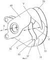
Фиг.1 изображает выполнение пар пережимающих пластин пережимающего узла в первом положении;Figure 1 depicts the implementation of a pair of pinch plates of the pinch node in the first position;
фиг.2 - выполнение пар пережимающих пластин пережимающего узла из фиг.1 во втором положении.figure 2 - the implementation of the pairs of pinch plates of the pinch node of figure 1 in the second position.
На фиг.1 пережимающий узел 1 содержит первую пару пережимающих пластин 10, 20 и вторую пару пережимающих пластин 30, 40, которые расположены параллельно друг другу с возможностью реверсивного поворота друг к другу вокруг общей оси А. Для реверсивного поворота пережимающих пластин 10, 20, 30, 40 предусмотрен привод (не показан), который воздействует на направленные от оси А поворота влево концы пережимающих пластин 10, 20, 30, 40. Первые 10, 20 и вторые 30, 40 пережимающие пластины обеих пар расположены рядом друг с другом, по меньшей мере, приблизительно совпадая между собой. Направленные от оси А поворота в направлении оси Z жгута концы пережимающих пластин крюкообразно загнуты так, что концы первых 10, 20 и вторых 30, 40 пережимающих пластин направлены друг к другу, причем их острия незначительно перекрываются.In Fig. 1, the pinch assembly 1 comprises a first pair of
Как видно на фиг.1, первые пережимающие пластины 30 второй пары 30, 40 короче первых пережимающих пластин 10 первой пары 10, 20. Пережимающие пластины 30 заканчиваются, если смотреть от оси А, непосредственно за вырезом V на концевом участке 32.As can be seen in FIG. 1, the
На направленной к пережимающим пластинам 30 стороне пережимающих пластин 10 расположена накладка 50. Пластинообразная накладка или пластина 50 соответствует по толщине и контуру участку пережимающих пластин 10, на котором она закреплена и к которому она прилегает всей поверхностью, совпадая с ним.On the side of the
На фиг.1 пары пережимающих пластин 10, 20, 30, 40 изображены в первом или исходном положении, в котором они разведены в осевом и радиальном направлениях.In figure 1, the pairs of
Как хорошо видно на фиг.1, первые пережимающие пластины 30 второй пары 30, 40 укорочены по сравнению с первыми пережимающими пластинами 10 первой пары 10, 20. Соответствующая этому укорочению пластина 50 расположена на обращенной к второй паре пережимающих пластин 30, 40 стороне пережимающих пластин 10 и прочно соединена с ней.As can be clearly seen in FIG. 1, the
На фиг.2 пережимающие пластины 10, 20, 30, 40 пережимающего узла изображены во втором положении или положении пережатия. В этом положении обе пары пережимающих пластин аксиально прижаты друг к другу по отношению к оси А настолько, что первые пережимающие пластины 10, 30 обеих пар 10, 20, 30, 40 прилегают друг к другу своими обращенными друг к другу боковыми поверхностями.2, the
При этом хорошо видно, что накладка 50 по своему контуру приблизительно идентична той части, на которую укорочены пережимающие пластины 30. Обращенные друг к другу торцевые поверхности концевого участка 32 пережимающих пластин 30 и пластина 50 образуют между собой зазор 60. Он препятствует столкновению или сцеплению пережимающих пластин 10, 30 при разводке или схождении пар 10, 20, 30, 40. Для улучшения этого эффекта зазор 60 ориентирован под острым углом к плоскости, проходящей вертикально через ось Z жгута. При этом зазор 60 и видимая на фиг.2 передняя сторона пережимающих пластин 30 образуют между собой угол, который вместе с упомянутым острым углом образует прямой угол.It can be clearly seen that the
Поскольку накладка 50 по своей толщине совпадает с той частью, на которую укорочены пережимающие пластины 30, видимые на фиг.2 передние стороны пережимающих пластин 30 и пластины 50 лежат в одной плоскости. Этим достигается то, что скользящие вдоль этой поверхности пережимающие пластины 40 без сопротивления могут направляться по образованному между пережимающими пластинами 40 и пластиной 50 зазору 60, не цепляясь за зазор 60. Чтобы обеспечить без проблем перетяжку и надежно предотвратить зацепление пережимающих пластин 40 за зазор 60, пластина 50 может быть выполнена чуть толще концевого участка 32 пережимающих пластин 30.Since the
Накладка или пластина 50 заполняет при этом пространство, возникшее в результате укорочения пережимающих пластин 30, когда последние прилегают к пережимающим пластинам 10. Это значит, что она простирается от концевого участка 32 пережимающих пластин 30 до острия крюкообразно загнутого конца пережимающих пластин 10.The patch or
На фиг.2 пары пережимающих пластин 10, 20, 30, 40 изображены в положении пережатия, в котором они прижаты друг к другу в осевом направлении по отношению к оси Z жгута, однако радиально еще разведены. Из этого положения начинается процесс пережатия заполненного упаковочного рукава (не показан). Процесс пережатия заканчивается, когда диаметр заполненной упаковочной оболочки уменьшен настолько, что на пережатом участке или в пережатом жгуте продукт отсутствует. Образованный из сосборенного упаковочного рукава жгут заполняет при этом пережимающее отверстие, образованное вырезами V прижатых друг к другу пережимающих пластин 10, 20, 30, 40. Затем начинается осевая разводка, т.е. пары пережимающих пластин 10, 20, 30, 40 расходятся в направлении жгута. Последующий продукт выдавливается, и между парами пережимающих пластин 10, 20, 30, 40 образуется свободный от продукта жгут, на который могут быть поставлены одна или две скобки или клипсы (не показаны). После этого пережимающие пластины 10, 20, 30, 40 радиально расходятся. Этим достигается исходное положение на фиг.1, в котором концы жгута освобождаются. Готовое колбасное изделие может быть извлечено из клипсатора, а новое колбасное изделие - изготовлено в результате следующего процесса наполнения.In figure 2, the pairs of
За счет накладки 50 на пережимающих пластинах 10 заполняется свободное пространство, возникающее в результате использования укороченных пережимающих пластин 30. Когда пары пережимающих пластин 10, 20, 30, 40 находятся в положении пережатия на фиг.2, острие пережимающих пластин 40 прилегает к накладке 50, вдоль которой пережимающие пластины 40 направляются при пережатии, пока они не достигнут укороченных пережимающих пластин 30. Заполнение свободного пространства накладкой 50 препятствует защемлению в этом месте упаковочного рукава или зацеплению укороченных пережимающих пластин 30 за концевой участок 32.Due to the lining 50 on the
Когда пары пережимающих пластин 10, 20, 30, 40 находятся в исходном положении, готовое колбасное изделие может быть извлечено из клипсатора. Заправка элемента для подвешивания колбасного изделия исключена за счет укороченных пережимающих пластин 30.When the pairs of
Следует заметить, что выполненный таким образом пережимающий узел не ограничен изготовлением колбасных изделий большого калибра и/или колбасных изделий в особенно восприимчивом упаковочном рукаве, а подходит для изготовления колбасных изделий любого калибра и в упаковочном рукаве из любого материала.It should be noted that the pinch assembly made in this way is not limited to the manufacture of sausages of large caliber and / or sausages in a particularly susceptible packaging sleeve, but is suitable for the manufacture of sausages of any caliber and in a packaging sleeve from any material.
В принципе, накладка 50 изготовлена из того же материала, что и пары пережимающих пластин 10, 20, 30, 40. Если они изготовлены из металла, то накладка 50 может быть приварена к пережимающим пластинам 10. Однако накладка 50 может быть изготовлена также из пластика. В этом случае она может быть привинчена к пережимающим пластинам 10. Поскольку на накладку 50 не действуют никакие экстремальные усилия, может быть также достаточным приклеить ее к пережимающим пластинам 10.In principle, the
Кроме того, можно дооснастить накладкой любой пережимающий узел, содержащий описанные выше пары пережимающих пластин. В простейшем случае отделенная от пережимающих пластин 30 часть в виде накладки 50 может быть размещена на задних пережимающих пластинах 10.In addition, any pinch assembly comprising the pinch plate pairs described above can be retrofitted with an overlay. In the simplest case, the part in the form of a lining 50 separated from the
Изобретение было описано выше на примере установленных с возможностью поворота вокруг общей оси и радиально сходящихся для пережатия пережимающих пластин. Разумеется, изобретение может быть реализовано также с линейно и реверсивно сходящимися пережимающими пластинами.The invention has been described above with the example of pinch plates mounted rotatably around a common axis and radially converging for clamping. Of course, the invention can also be implemented with linearly and reversibly converging pinch plates.
Линейно функционирующие пережимающие пластины имеют направленную к оси жгута V-образную выемку, образованную лежащими рядом с боков остриями. Согласно изобретению одно из направленных к оси жгута остриев нижних пережимающих пластин может быть укорочено. Соответствующая этому укорочению накладка располагается тогда на соответствующих верхних пережимающих пластинах.Linearly functioning pinch plates have a V-shaped recess directed to the axis of the bundle, formed by points lying near the sides. According to the invention, one of the points of the lower pinch plates directed towards the axis of the bundle can be shortened. The patch corresponding to this shortening is then located on the corresponding upper pinch plates.
Расположение зазора между укороченными пережимающими пластинами и накладкой соответствует изображенному на чертежах примеру.The location of the gap between the shortened pinch plates and the overlay corresponds to the example shown in the drawings.
Claims (11)
Applications Claiming Priority (2)
| Application Number | Priority Date | Filing Date | Title |
|---|---|---|---|
| DE102008057293A DE102008057293A1 (en) | 2008-11-14 | 2008-11-14 | Displacer assembly for a clip machine |
| DE102008057293.4 | 2008-11-14 |
Publications (2)
| Publication Number | Publication Date |
|---|---|
| RU2009141994A RU2009141994A (en) | 2011-05-20 |
| RU2425784C1 true RU2425784C1 (en) | 2011-08-10 |
Family
ID=41698322
Family Applications (1)
| Application Number | Title | Priority Date | Filing Date |
|---|---|---|---|
| RU2009141994/21A RU2425784C1 (en) | 2008-11-14 | 2009-11-13 | Clamping unit of clip mechanism |
Country Status (5)
| Country | Link |
|---|---|
| US (1) | US8113925B2 (en) |
| EP (1) | EP2186415B1 (en) |
| DE (1) | DE102008057293A1 (en) |
| ES (1) | ES2470741T3 (en) |
| RU (1) | RU2425784C1 (en) |
Families Citing this family (7)
| Publication number | Priority date | Publication date | Assignee | Title |
|---|---|---|---|---|
| EP2363027B2 (en) * | 2010-03-05 | 2019-03-27 | Poly-clip System GmbH & Co. KG | System and method for allowing a quality check of sausage-shaped products |
| EP2384639B2 (en) * | 2010-05-06 | 2024-02-14 | Poly-clip System GmbH & Co. KG | Loading station for a storage frame |
| USD708029S1 (en) * | 2012-01-03 | 2014-07-01 | James Scott Kleiber, Jr. | Sausage end declipper |
| US20150056902A1 (en) * | 2013-08-26 | 2015-02-26 | Marel Meat Processing Inc. | Partial crimping device and method of using the same |
| EA031935B1 (en) * | 2016-10-10 | 2019-03-29 | Общество с ограниченной ответственностью "Машиностроительное предприятие "КОМПО" | Pinching unit for a clip-applier (embodiments) |
| USD995200S1 (en) * | 2020-07-29 | 2023-08-15 | Freddy Hirsch Group Ag | Sausage cutter |
| USD1045496S1 (en) * | 2020-08-21 | 2024-10-08 | H.J. Heinz Company Brands Llc | Pouch piercer |
Citations (3)
| Publication number | Priority date | Publication date | Assignee | Title |
|---|---|---|---|---|
| EP0302966A2 (en) * | 1987-08-13 | 1989-02-15 | Teepak, Inc. | Constricting and fastening apparatus |
| RU2162638C1 (en) * | 2000-06-20 | 2001-02-10 | Закрытое акционерное общество "Клипмаш" | Clipper |
| EA005436B1 (en) * | 2003-03-19 | 2005-02-24 | Умп "Компо" | Clipping apparatus |
Family Cites Families (13)
| Publication number | Priority date | Publication date | Assignee | Title |
|---|---|---|---|---|
| US1545586A (en) * | 1924-03-12 | 1925-07-14 | Kruse Ferdinand | Sausage-twisting machine |
| US3296657A (en) * | 1963-12-24 | 1967-01-10 | Charles D Moekle | Method for making linked products |
| US3328835A (en) * | 1964-11-17 | 1967-07-04 | Linker Machines | Casing linking machine for sausage and the like |
| DE1586210C3 (en) * | 1967-08-11 | 1976-09-02 | Niedecker Herbert | Device for dividing packages from a filled tube |
| DE2550042C2 (en) | 1975-11-07 | 1982-12-02 | Herbert Dipl.-Ing. 6240 Königstein Niedecker | Device for dividing packages from a filled tube |
| US4214492A (en) * | 1978-12-26 | 1980-07-29 | Hoffman Thomas M | Method and apparatus for cutting clips off of the ends of sausages and the like |
| DE3121101C1 (en) * | 1981-05-27 | 1982-11-04 | Herbert Dipl.-Ing. 6240 Königstein Niedecker | Process for filling and closing sausage casings closed at the end on a combined filling and closing machine |
| US4463477A (en) * | 1981-07-02 | 1984-08-07 | Devro, Inc. | Apparatus for separating stuffed sausage links |
| NL8900292A (en) * | 1989-02-06 | 1990-09-03 | Stork Protecon Bv | SCISSOR SYSTEM FOR STRINGING AND SEPARATING A SAUSAGE STRING. |
| NL8901026A (en) * | 1989-04-24 | 1990-11-16 | Stork Protecon Bv | DRAINER FOR STRAIGHT SAUSAGES FROM A MACHINE FOR MANUFACTURE THEREOF. |
| EP1095570A1 (en) | 1999-10-29 | 2001-05-02 | Tipper Tie Alpina AG | Double clipper device |
| NL1025005C2 (en) * | 2003-12-12 | 2005-06-14 | Townsend Engineering B V | Method for the phased separation of a sausage strand, separation element and assembly of separation elements. |
| DE202006012324U1 (en) | 2006-08-10 | 2006-12-21 | Poly-Clip System Gmbh & Co. Kg | Clipping machine comprises at least two pairs of displacement elements whose radial direction of motion roughly corresponds to the radial direction of motion of the closure tools |
-
2008
- 2008-11-14 DE DE102008057293A patent/DE102008057293A1/en not_active Ceased
-
2009
- 2009-11-09 ES ES09014011.2T patent/ES2470741T3/en active Active
- 2009-11-09 EP EP09014011.2A patent/EP2186415B1/en active Active
- 2009-11-11 US US12/616,481 patent/US8113925B2/en active Active
- 2009-11-13 RU RU2009141994/21A patent/RU2425784C1/en active
Patent Citations (3)
| Publication number | Priority date | Publication date | Assignee | Title |
|---|---|---|---|---|
| EP0302966A2 (en) * | 1987-08-13 | 1989-02-15 | Teepak, Inc. | Constricting and fastening apparatus |
| RU2162638C1 (en) * | 2000-06-20 | 2001-02-10 | Закрытое акционерное общество "Клипмаш" | Clipper |
| EA005436B1 (en) * | 2003-03-19 | 2005-02-24 | Умп "Компо" | Clipping apparatus |
Also Published As
| Publication number | Publication date |
|---|---|
| US8113925B2 (en) | 2012-02-14 |
| EP2186415B1 (en) | 2014-05-07 |
| US20100124874A1 (en) | 2010-05-20 |
| EP2186415A1 (en) | 2010-05-19 |
| RU2009141994A (en) | 2011-05-20 |
| ES2470741T3 (en) | 2014-06-24 |
| DE102008057293A1 (en) | 2010-05-27 |
Similar Documents
| Publication | Publication Date | Title |
|---|---|---|
| RU2425784C1 (en) | Clamping unit of clip mechanism | |
| DE2745387C2 (en) | Device for attaching a hanging loop to a food casing | |
| US9434489B2 (en) | Computer program products for systems with cooperating reruckers for producing encased products | |
| US7306511B2 (en) | Systems with interchangeable horns for producing encased products and related methods, computer program products and horn rotor assemblies | |
| US20090130963A1 (en) | Apparatus for the automatic stuffing of meat products into a double casing comprising a sheet and a net | |
| US20070245690A1 (en) | Clippers with translating gate members and cooperating stiffener assemblies and related methods, computer program products | |
| NL8202394A (en) | METHOD AND APPARATUS FOR FILLING FOOD PRODUCTS IN A PLEATED COVER | |
| NO811349L (en) | PROCEDURE AND APPARATUS FOR STAPPING SOFT ARTICLES INTO Separate Lengths of Wrap Material | |
| US8636564B2 (en) | Supply device for hanging elements | |
| US6920738B2 (en) | Push/pull clip feed configuration for selectively delivering or withdrawing a clip to allow output of one clip alone or two clips concurrently and associated devices, methods, systems and computer program products | |
| DE2521846C3 (en) | Tubular film with a non-slip tie with a hanging loop for wrapping food and processes for its production | |
| NO156352B (en) | POULTRY SHOULDER WITH A FLATED END PART, PROCEDURE FOR CLOSING A POULTRY HOUSING STRING, AND APPARATUS FOR CLOSING A STRING WITH POOL HOUSING. | |
| RU2532980C2 (en) | Capsule with explosives containing detonating means | |
| US10005578B2 (en) | Clipping tool assembly | |
| US20140000216A1 (en) | Clipping machine | |
| DE2804191A1 (en) | Hot dogs in brine - packed in plastic bags by lowering hose from filler tube and applying clips after filling | |
| US9598193B2 (en) | Clipping device and method controlling said clipping device | |
| DE69018664T2 (en) | Method and device for calibrating and braking for food filling machines. | |
| AU2006259327A1 (en) | Clip closure system | |
| BE837331A (en) | MEASURE FOR STRENGTHENING PRODUCTS PACKAGED IN INTESTINES AND SIMILAR CASES | |
| CA2565016C (en) | Belt fed food casing system | |
| AU2001238727A1 (en) | Method and apparatus for precrimping a sausage strand | |
| CN1209781A (en) | Method and apparatus for packaging perforated food | |
| RU86413U1 (en) | STAPLE CAP | |
| EP2457445A2 (en) | Closing device for forming sausage-shaped packages |