RU2425981C1 - Rotary-arc engine - Google Patents
Rotary-arc engine Download PDFInfo
- Publication number
- RU2425981C1 RU2425981C1 RU2010106710/06A RU2010106710A RU2425981C1 RU 2425981 C1 RU2425981 C1 RU 2425981C1 RU 2010106710/06 A RU2010106710/06 A RU 2010106710/06A RU 2010106710 A RU2010106710 A RU 2010106710A RU 2425981 C1 RU2425981 C1 RU 2425981C1
- Authority
- RU
- Russia
- Prior art keywords
- working
- shaft
- working chambers
- separator
- block
- Prior art date
Links
- 239000012530 fluid Substances 0.000 claims description 9
- 230000001360 synchronised effect Effects 0.000 claims 1
- 230000003247 decreasing effect Effects 0.000 abstract 1
- 230000000694 effects Effects 0.000 abstract 1
- 239000000126 substance Substances 0.000 abstract 1
- 239000007789 gas Substances 0.000 description 5
- 238000002485 combustion reaction Methods 0.000 description 3
- 244000309464 bull Species 0.000 description 1
- 238000010586 diagram Methods 0.000 description 1
- 238000000605 extraction Methods 0.000 description 1
- 238000009434 installation Methods 0.000 description 1
- 238000012423 maintenance Methods 0.000 description 1
- 238000004519 manufacturing process Methods 0.000 description 1
- 239000000203 mixture Substances 0.000 description 1
- XLYOFNOQVPJJNP-UHFFFAOYSA-N water Chemical compound O XLYOFNOQVPJJNP-UHFFFAOYSA-N 0.000 description 1
Images
Landscapes
- Engine Equipment That Uses Special Cycles (AREA)
Abstract
Description
Изобретение относится к двигателестроению, а именно к роторным двигателям, работающим на горящих газах или на водяном паре, а также на смеси рабочих тел.The invention relates to engine building, namely to rotary engines operating on burning gases or water vapor, as well as on a mixture of working bodies.
Известен турбинно-дуговой двигатель по патенту RU 2184861 C1, опубл. 10.07.02 г., бюл. №19, отличающийся тем, что рабочее тело поступает из камеры сгорания в рабочую камеру через дозирующее устройство, расположенное между камерой сгорания и рабочей камерой, и настроено дозирующее устройство так, чтобы давление рабочего тела, вращающего рабочий вал, к началу выхлопа уравнялось с атмосферным. Дозирование подаваемой в рабочую камеру порции газа осуществляется с той целью, чтобы в процессе расширения газа в ограниченном пространстве рабочей камеры производился максимально возможный отбор энергии из содержащегося в порции газа энергетического заряда, чем и достигается повышение кпд двигателя и снижение количества экологически вредных выбросов, производимых двигателем на единицу мощности.Known turbine-arc engine according to patent RU 2184861 C1, publ. 07/10/02, bull. No. 19, characterized in that the working fluid enters from the combustion chamber into the working chamber through a metering device located between the combustion chamber and the working chamber, and the metering device is configured so that the pressure of the working fluid rotating the working shaft equals atmospheric pressure at the beginning of the exhaust. Dosing of a portion of gas supplied to the working chamber is carried out with the aim of maximizing energy extraction from the energy charge contained in the portion of gas during gas expansion in a limited space of the working chamber, thereby increasing the efficiency of the engine and reducing the amount of environmentally harmful emissions produced by the engine per unit of power.
Недостатком турбинно-дугового двигателя является то, что сепаратор сочетается только с одним рабочим валом и, следовательно, не осуществляются потенциальные возможности по массогабаритным показателям двигателя.The disadvantage of a turbine-arc engine is that the separator is combined with only one working shaft and, therefore, the potential opportunities for the overall dimensions of the engine are not realized.
Задачей, на решение которой направлено заявляемое изобретение, является создание более компактной конструкции двигателя и улучшение его массогабаритных показателей.The problem to which the invention is directed, is to create a more compact design of the engine and improve its overall dimensions.
Массогабаритные показатели улучшаются за счет того, что в отличие от аналога, где один сепаратор сочетается только с одним рабочим валом, в заявляемом изобретении с одним сепаратором сочетаются два или более рабочих вала с закрепленными на них лопастями, помещенными в один корпус, закрытый торцовыми плитами, и эти элементы образуют комплекс соответственно из двух или более рабочих камер дугообразной формы. Объем и масса такого комплекса будет при прочих равных условиях непременно меньше, чем если бы каждый рабочий вал сочетался только со своим отдельным сепаратором.The overall dimensions are improved due to the fact that, unlike the analogue, where one separator is combined with only one working shaft, in the claimed invention two or more working shafts are combined with one separator with blades mounted on them, placed in one housing, closed by end plates, and these elements form a complex, respectively, of two or more working chambers of an arched shape. All other things being equal, the volume and mass of such a complex will certainly be less than if each working shaft were combined only with its own separate separator.
Заявляемое изобретение направлено также на получение возможности варьировать габаритными размерами двигателя и величиной производимой им мощности не только путем изменения параметров рабочего тела или изменения размеров элементов рабочих камер, но и путем изменения компоновки блока рабочих камер.The invention is also aimed at obtaining the ability to vary the overall dimensions of the engine and the amount of power it produces, not only by changing the parameters of the working fluid or by changing the dimensions of the elements of the working chambers, but also by changing the layout of the block of working chambers.
Так как блок рабочих камер может содержать не только один комплекс, но и батарею из нескольких одинаковых комплексов, то меняя число комплексов в блоке можно кратчайшим путем решать вопросы изменения мощности и варьировать габаритными размерами двигателя. Варьировать габаритными размерами двигателя бывает необходимо для его рационального размещения при монтаже на транспортных машинах.Since the block of working chambers can contain not only one complex, but also a battery of several identical complexes, changing the number of complexes in the block can solve the issues of changing power in the shortest way and vary the overall dimensions of the engine. Varying the overall dimensions of the engine is sometimes necessary for its rational placement during installation on transport vehicles.
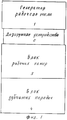
На фиг.1 изображена блок-схема двигателя, которая состоит из следующих элементов.Figure 1 shows a block diagram of an engine, which consists of the following elements.
1. Генератор рабочего тела 1. В качестве генератора рабочего тела может применяться камера сгорания или парогенератор.1. Generator of the working
2. Дозирующее устройство 2.2. Dosing device 2.
3. Блок рабочих камер 3. В корпусе блока рабочих камер может размешаться один или несколько комплексов рабочих камер.3. The block of working
4. Блок зубчатых колес 4. В корпусе блока зубчатых колес размещаются зубчатые колеса и коллекторный вал.4. The block of
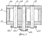
На фиг.2 изображен в разрезе вдоль осей рабочих валов вариант блока рабочих камер, содержащий один комплекс из двух рабочих камер 22 и 23.Figure 2 shows a section along the axes of the working shafts of a variant of the block of working chambers containing one complex of two working
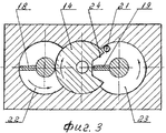
На фиг.3 изображен тот же блок, что и на фиг.2, но в сечении, перпендикулярном осям рабочих валов.Figure 3 shows the same block as in figure 2, but in a section perpendicular to the axes of the working shafts.
Комплекс, содержащийся в блоке, образован следующими элементами: корпусом 11, торцовыми плитами 12 и 13, сепаратором 14, валом сепаратора 15 и рабочими валами 16 и 17 с лопастями 18 и 19. В торцовой плите 12 имеется впускное отверстие 20. В торцовой плите 13 имеется выпускное отверстие 21.The complex contained in the block is formed by the following elements: the
На валах 15, 16 и 17, которые имеют продолжение в блоке зубчатых колес (фиг.5), закреплены синхронизирующие зубчатые колеса 51, 52 и 53.On the
На фиг.4 в сечении, перпендикулярном осям рабочих валов, изображен блок рабочих камер, содержащий в корпусе 40 три двухкамерных комплекса 41, 42 и 43.In Fig. 4, a section perpendicular to the axes of the working shafts shows a block of working chambers containing three two-chamber complexes 41, 42 and 43 in the housing 40.
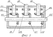
На фиг.5 в вертикальном сечении вдоль осей валов сепараторов изображен блок зубчатых передач. В корпусе 50 блока зубчатых колес на валах 15, 16 и 17 размещаются синхронизирующие цилиндрические колеса 51, 52, 53, а на валу 15 также и коническое колесо 54. На коллекторном валу 55 закреплены конические зубчатые колеса 56, 57 и 58.Figure 5 in a vertical section along the axes of the shafts of the separators shows a block of gears. In the
Производство двигателя возможно на большинстве машиностроительных заводов страны.Engine production is possible at most engineering plants in the country.
Двигатель, изображенный на фиг.1, скомпонован на блочной основе с возможностью быстрого отсоединения блоков для удобства ремонта и проведения регламентных работ.The engine shown in figure 1, is arranged on a block basis with the ability to quickly disconnect blocks for ease of repair and routine maintenance.
Работает двигатель следующим образом. От генератора рабочего тела 1 через дозирующее устройство 2 и впускное отверстие 20 в верхней торцевой плите 12 порция рабочего тела поступает в рабочие камеры 22 и 23, давит на лопасти 18 и 19. Лопасти, вследствие давления рабочего тела, перемещаются и, будучи жестко связанными с рабочими валами 16 и 17, вращают их. Далее крутящий момент через синхронизирующие зубчатые колеса 52 и 53 передается на синхронизирующее зубчатое колесо 51 и, таким образом, на вал сепаратора 15. Затем на коническое зубчатое колесо 54 и далее по предназначению на ходовую часть транспортной машины или на электрогенератор и т.п.The engine operates as follows. From the generator of the working
Одновременно с валом сепаратора 15 вращается закрепленный на нем сепаратор 14. В процессе вращения лопасть совмещается с имеющейся на сепараторе впадиной 24 и пропускается, таким образом, в исходное положение для совершения очередного цикла. Удаление отработанных газов осуществляется через выпускное отверстие 21 в нижней торцовой плите 13.Simultaneously with the shaft of the
Если блок рабочих камер содержит несколько комплексов рабочих камер, как на фиг.4, то вращение через валы сепараторов будет передаваться в блок зубчатых шестерен и в нем через конические пары зубчатых колес на коллекторный вал 55 и далее от него - по предназначению.If the block of working chambers contains several sets of working chambers, as in Fig. 4, then rotation through the shafts of the separators will be transmitted to the block of gear gears and in it through bevel pairs of gear wheels to the
Claims (1)
Priority Applications (1)
| Application Number | Priority Date | Filing Date | Title |
|---|---|---|---|
| RU2010106710/06A RU2425981C1 (en) | 2010-02-24 | 2010-02-24 | Rotary-arc engine |
Applications Claiming Priority (1)
| Application Number | Priority Date | Filing Date | Title |
|---|---|---|---|
| RU2010106710/06A RU2425981C1 (en) | 2010-02-24 | 2010-02-24 | Rotary-arc engine |
Publications (1)
| Publication Number | Publication Date |
|---|---|
| RU2425981C1 true RU2425981C1 (en) | 2011-08-10 |
Family
ID=44754620
Family Applications (1)
| Application Number | Title | Priority Date | Filing Date |
|---|---|---|---|
| RU2010106710/06A RU2425981C1 (en) | 2010-02-24 | 2010-02-24 | Rotary-arc engine |
Country Status (1)
| Country | Link |
|---|---|
| RU (1) | RU2425981C1 (en) |
Citations (6)
| Publication number | Priority date | Publication date | Assignee | Title |
|---|---|---|---|---|
| US3701254A (en) * | 1970-06-12 | 1972-10-31 | Oskar Michejda | Rotary piston engine |
| RU2135778C1 (en) * | 1998-06-05 | 1999-08-27 | Соколов Виктор Евгеньевич | Rotary machine |
| RU2184861C1 (en) * | 2000-11-15 | 2002-07-10 | Флаксман Абрам Носонович | Turbine arc engine |
| JP2007224894A (en) * | 2006-02-24 | 2007-09-06 | Masahiro Ikemura | Bidirectional conversion apparatus of pressure and turning force |
| RU2325542C2 (en) * | 2006-06-13 | 2008-05-27 | Алексей Кадырович Ашмарин | Multi rotor internal combustion engine |
| WO2009013110A1 (en) * | 2007-07-20 | 2009-01-29 | Franz Ackerl | Rotary piston engine |
-
2010
- 2010-02-24 RU RU2010106710/06A patent/RU2425981C1/en not_active IP Right Cessation
Patent Citations (6)
| Publication number | Priority date | Publication date | Assignee | Title |
|---|---|---|---|---|
| US3701254A (en) * | 1970-06-12 | 1972-10-31 | Oskar Michejda | Rotary piston engine |
| RU2135778C1 (en) * | 1998-06-05 | 1999-08-27 | Соколов Виктор Евгеньевич | Rotary machine |
| RU2184861C1 (en) * | 2000-11-15 | 2002-07-10 | Флаксман Абрам Носонович | Turbine arc engine |
| JP2007224894A (en) * | 2006-02-24 | 2007-09-06 | Masahiro Ikemura | Bidirectional conversion apparatus of pressure and turning force |
| RU2325542C2 (en) * | 2006-06-13 | 2008-05-27 | Алексей Кадырович Ашмарин | Multi rotor internal combustion engine |
| WO2009013110A1 (en) * | 2007-07-20 | 2009-01-29 | Franz Ackerl | Rotary piston engine |
Similar Documents
| Publication | Publication Date | Title |
|---|---|---|
| CA2821497C (en) | Compound cycle engine | |
| RU2013153153A (en) | HYBRID INTERNAL COMBUSTION ENGINE (OPTIONS) | |
| JP2013527355A (en) | Rotating piston steam engine with balanced rotary variable intake cutoff valve and second expansion with no back pressure in the first expansion | |
| JP2010533259A5 (en) | ||
| CN105756714A (en) | Sliding vane type steam-driven rotary engine | |
| RU2435281C1 (en) | Generator plant | |
| RU2538990C1 (en) | Rotor-piston internal combustion engine | |
| US20200123901A1 (en) | Six-stroke rotary-vane internal combustion engine | |
| CN104234825A (en) | Coaxial double-cylinder combined engine with cam rotors | |
| RU2301349C2 (en) | Rotary sector turbine engine | |
| RU2322595C1 (en) | Power plant | |
| RU2006120317A (en) | MULTOROTOR INTERNAL COMBUSTION ENGINE | |
| CN105464710A (en) | Sliding piece type steam-driven rotor engine | |
| US20100258075A1 (en) | Vane-Type Rotary Actuator or an Internal Combustion Machine | |
| GB783913A (en) | Improved rotary engine | |
| RU2235895C2 (en) | Rotary sector engine | |
| RU2184861C1 (en) | Turbine arc engine | |
| RU112278U1 (en) | ROTARY-VEINED INTERNAL COMBUSTION ENGINE | |
| RU2743607C1 (en) | Rotary-blade internal combustion engine | |
| RU112946U1 (en) | RING INTERNAL COMBUSTION ENGINE WITH PUMPING PLATE-PISTON | |
| RU2754834C1 (en) | Rotary detonation engine | |
| CN205445684U (en) | Sliding vane type steam -operating rotary engine | |
| CN205638567U (en) | Sliding vane type steam -operating rotary engine | |
| RU2413077C2 (en) | Rotary wave motor | |
| CN102345506A (en) | Novel screw rotor engine |
Legal Events
| Date | Code | Title | Description |
|---|---|---|---|
| MM4A | The patent is invalid due to non-payment of fees |
Effective date: 20150225 |