RU2456110C2 - Method of producing steel bearing-capacity structural element by clinching metal parts, clinching tool and steel structural element - Google Patents
Method of producing steel bearing-capacity structural element by clinching metal parts, clinching tool and steel structural element Download PDFInfo
- Publication number
- RU2456110C2 RU2456110C2 RU2009134108/02A RU2009134108A RU2456110C2 RU 2456110 C2 RU2456110 C2 RU 2456110C2 RU 2009134108/02 A RU2009134108/02 A RU 2009134108/02A RU 2009134108 A RU2009134108 A RU 2009134108A RU 2456110 C2 RU2456110 C2 RU 2456110C2
- Authority
- RU
- Russia
- Prior art keywords
- steel
- punch
- metal
- metal parts
- tool
- Prior art date
Links
- 229910000831 Steel Inorganic materials 0.000 title claims abstract description 112
- 239000010959 steel Substances 0.000 title claims abstract description 112
- 229910052751 metal Inorganic materials 0.000 title claims abstract description 96
- 239000002184 metal Substances 0.000 title claims abstract description 96
- 238000000034 method Methods 0.000 title claims description 30
- 230000007704 transition Effects 0.000 claims abstract description 38
- XEEYBQQBJWHFJM-UHFFFAOYSA-N Iron Chemical compound [Fe] XEEYBQQBJWHFJM-UHFFFAOYSA-N 0.000 claims description 14
- 238000009434 installation Methods 0.000 claims description 14
- 238000004519 manufacturing process Methods 0.000 claims description 13
- 238000007654 immersion Methods 0.000 claims description 8
- 229910052742 iron Inorganic materials 0.000 claims description 7
- 238000010276 construction Methods 0.000 claims description 6
- -1 or a flat sheet Substances 0.000 claims description 5
- 238000000926 separation method Methods 0.000 claims description 4
- 230000001681 protective effect Effects 0.000 claims 6
- RYGMFSIKBFXOCR-UHFFFAOYSA-N Copper Chemical compound [Cu] RYGMFSIKBFXOCR-UHFFFAOYSA-N 0.000 claims 4
- 229910052782 aluminium Inorganic materials 0.000 claims 4
- XAGFODPZIPBFFR-UHFFFAOYSA-N aluminium Chemical compound [Al] XAGFODPZIPBFFR-UHFFFAOYSA-N 0.000 claims 4
- 229910052802 copper Inorganic materials 0.000 claims 4
- 239000010949 copper Substances 0.000 claims 4
- 238000007670 refining Methods 0.000 claims 2
- YPFNIPKMNMDDDB-UHFFFAOYSA-K 2-[2-[bis(carboxylatomethyl)amino]ethyl-(2-hydroxyethyl)amino]acetate;iron(3+) Chemical compound [Fe+3].OCCN(CC([O-])=O)CCN(CC([O-])=O)CC([O-])=O YPFNIPKMNMDDDB-UHFFFAOYSA-K 0.000 claims 1
- 238000000605 extraction Methods 0.000 claims 1
- XLYOFNOQVPJJNP-UHFFFAOYSA-N water Substances O XLYOFNOQVPJJNP-UHFFFAOYSA-N 0.000 claims 1
- 230000000694 effects Effects 0.000 abstract description 5
- 238000003754 machining Methods 0.000 abstract description 3
- 230000035515 penetration Effects 0.000 abstract description 2
- 238000010327 methods by industry Methods 0.000 abstract 1
- 239000000126 substance Substances 0.000 abstract 1
- 239000000463 material Substances 0.000 description 18
- 239000011159 matrix material Substances 0.000 description 17
- 238000005304 joining Methods 0.000 description 8
- 230000008901 benefit Effects 0.000 description 6
- 238000005520 cutting process Methods 0.000 description 6
- 230000015572 biosynthetic process Effects 0.000 description 5
- 230000008569 process Effects 0.000 description 5
- 238000003466 welding Methods 0.000 description 4
- 239000011248 coating agent Substances 0.000 description 3
- 238000000576 coating method Methods 0.000 description 3
- 230000007423 decrease Effects 0.000 description 3
- 238000005457 optimization Methods 0.000 description 3
- 238000002474 experimental method Methods 0.000 description 2
- 238000005461 lubrication Methods 0.000 description 2
- 230000004044 response Effects 0.000 description 2
- 238000004088 simulation Methods 0.000 description 2
- 238000012360 testing method Methods 0.000 description 2
- 101100545204 Danio rerio zdhhc18a gene Proteins 0.000 description 1
- 101150018368 Pigv gene Proteins 0.000 description 1
- 230000009286 beneficial effect Effects 0.000 description 1
- 238000004364 calculation method Methods 0.000 description 1
- 238000005253 cladding Methods 0.000 description 1
- 238000005260 corrosion Methods 0.000 description 1
- 238000011161 development Methods 0.000 description 1
- 230000009977 dual effect Effects 0.000 description 1
- 238000004049 embossing Methods 0.000 description 1
- 238000005516 engineering process Methods 0.000 description 1
- 238000000465 moulding Methods 0.000 description 1
- 238000001556 precipitation Methods 0.000 description 1
- 230000009467 reduction Effects 0.000 description 1
- 238000011160 research Methods 0.000 description 1
- 239000013049 sediment Substances 0.000 description 1
- 238000007514 turning Methods 0.000 description 1
Images






Classifications
-
- B—PERFORMING OPERATIONS; TRANSPORTING
- B21—MECHANICAL METAL-WORKING WITHOUT ESSENTIALLY REMOVING MATERIAL; PUNCHING METAL
- B21D—WORKING OR PROCESSING OF SHEET METAL OR METAL TUBES, RODS OR PROFILES WITHOUT ESSENTIALLY REMOVING MATERIAL; PUNCHING METAL
- B21D39/00—Application of procedures in order to connect objects or parts, e.g. coating with sheet metal otherwise than by plating; Tube expanders
- B21D39/03—Application of procedures in order to connect objects or parts, e.g. coating with sheet metal otherwise than by plating; Tube expanders of sheet metal otherwise than by folding
- B21D39/031—Joining superposed plates by locally deforming without slitting or piercing
-
- B—PERFORMING OPERATIONS; TRANSPORTING
- B21—MECHANICAL METAL-WORKING WITHOUT ESSENTIALLY REMOVING MATERIAL; PUNCHING METAL
- B21D—WORKING OR PROCESSING OF SHEET METAL OR METAL TUBES, RODS OR PROFILES WITHOUT ESSENTIALLY REMOVING MATERIAL; PUNCHING METAL
- B21D39/00—Application of procedures in order to connect objects or parts, e.g. coating with sheet metal otherwise than by plating; Tube expanders
- B21D39/03—Application of procedures in order to connect objects or parts, e.g. coating with sheet metal otherwise than by plating; Tube expanders of sheet metal otherwise than by folding
-
- B—PERFORMING OPERATIONS; TRANSPORTING
- B21—MECHANICAL METAL-WORKING WITHOUT ESSENTIALLY REMOVING MATERIAL; PUNCHING METAL
- B21J—FORGING; HAMMERING; PRESSING METAL; RIVETING; FORGE FURNACES
- B21J15/00—Riveting
- B21J15/02—Riveting procedures
-
- B—PERFORMING OPERATIONS; TRANSPORTING
- B66—HOISTING; LIFTING; HAULING
- B66B—ELEVATORS; ESCALATORS OR MOVING WALKWAYS
- B66B23/00—Component parts of escalators or moving walkways
-
- F—MECHANICAL ENGINEERING; LIGHTING; HEATING; WEAPONS; BLASTING
- F16—ENGINEERING ELEMENTS AND UNITS; GENERAL MEASURES FOR PRODUCING AND MAINTAINING EFFECTIVE FUNCTIONING OF MACHINES OR INSTALLATIONS; THERMAL INSULATION IN GENERAL
- F16B—DEVICES FOR FASTENING OR SECURING CONSTRUCTIONAL ELEMENTS OR MACHINE PARTS TOGETHER, e.g. NAILS, BOLTS, CIRCLIPS, CLAMPS, CLIPS OR WEDGES; JOINTS OR JOINTING
- F16B5/00—Joining sheets or plates, e.g. panels, to one another or to strips or bars parallel to them
- F16B5/04—Joining sheets or plates, e.g. panels, to one another or to strips or bars parallel to them by means of riveting
-
- F—MECHANICAL ENGINEERING; LIGHTING; HEATING; WEAPONS; BLASTING
- F16—ENGINEERING ELEMENTS AND UNITS; GENERAL MEASURES FOR PRODUCING AND MAINTAINING EFFECTIVE FUNCTIONING OF MACHINES OR INSTALLATIONS; THERMAL INSULATION IN GENERAL
- F16B—DEVICES FOR FASTENING OR SECURING CONSTRUCTIONAL ELEMENTS OR MACHINE PARTS TOGETHER, e.g. NAILS, BOLTS, CIRCLIPS, CLAMPS, CLIPS OR WEDGES; JOINTS OR JOINTING
- F16B5/00—Joining sheets or plates, e.g. panels, to one another or to strips or bars parallel to them
- F16B5/04—Joining sheets or plates, e.g. panels, to one another or to strips or bars parallel to them by means of riveting
- F16B5/045—Joining sheets or plates, e.g. panels, to one another or to strips or bars parallel to them by means of riveting without the use of separate rivets
-
- Y—GENERAL TAGGING OF NEW TECHNOLOGICAL DEVELOPMENTS; GENERAL TAGGING OF CROSS-SECTIONAL TECHNOLOGIES SPANNING OVER SEVERAL SECTIONS OF THE IPC; TECHNICAL SUBJECTS COVERED BY FORMER USPC CROSS-REFERENCE ART COLLECTIONS [XRACs] AND DIGESTS
- Y10—TECHNICAL SUBJECTS COVERED BY FORMER USPC
- Y10T—TECHNICAL SUBJECTS COVERED BY FORMER US CLASSIFICATION
- Y10T29/00—Metal working
- Y10T29/49—Method of mechanical manufacture
- Y10T29/49616—Structural member making
- Y10T29/49623—Static structure, e.g., a building component
-
- Y—GENERAL TAGGING OF NEW TECHNOLOGICAL DEVELOPMENTS; GENERAL TAGGING OF CROSS-SECTIONAL TECHNOLOGIES SPANNING OVER SEVERAL SECTIONS OF THE IPC; TECHNICAL SUBJECTS COVERED BY FORMER USPC CROSS-REFERENCE ART COLLECTIONS [XRACs] AND DIGESTS
- Y10—TECHNICAL SUBJECTS COVERED BY FORMER USPC
- Y10T—TECHNICAL SUBJECTS COVERED BY FORMER US CLASSIFICATION
- Y10T29/00—Metal working
- Y10T29/49—Method of mechanical manufacture
- Y10T29/49826—Assembling or joining
- Y10T29/49908—Joining by deforming
- Y10T29/49915—Overedge assembling of seated part
-
- Y—GENERAL TAGGING OF NEW TECHNOLOGICAL DEVELOPMENTS; GENERAL TAGGING OF CROSS-SECTIONAL TECHNOLOGIES SPANNING OVER SEVERAL SECTIONS OF THE IPC; TECHNICAL SUBJECTS COVERED BY FORMER USPC CROSS-REFERENCE ART COLLECTIONS [XRACs] AND DIGESTS
- Y10—TECHNICAL SUBJECTS COVERED BY FORMER USPC
- Y10T—TECHNICAL SUBJECTS COVERED BY FORMER US CLASSIFICATION
- Y10T29/00—Metal working
- Y10T29/49—Method of mechanical manufacture
- Y10T29/49826—Assembling or joining
- Y10T29/49908—Joining by deforming
- Y10T29/49924—Joining by deforming of parallel side-by-side elongated members
-
- Y—GENERAL TAGGING OF NEW TECHNOLOGICAL DEVELOPMENTS; GENERAL TAGGING OF CROSS-SECTIONAL TECHNOLOGIES SPANNING OVER SEVERAL SECTIONS OF THE IPC; TECHNICAL SUBJECTS COVERED BY FORMER USPC CROSS-REFERENCE ART COLLECTIONS [XRACs] AND DIGESTS
- Y10—TECHNICAL SUBJECTS COVERED BY FORMER USPC
- Y10T—TECHNICAL SUBJECTS COVERED BY FORMER US CLASSIFICATION
- Y10T29/00—Metal working
- Y10T29/49—Method of mechanical manufacture
- Y10T29/49826—Assembling or joining
- Y10T29/49908—Joining by deforming
- Y10T29/49936—Surface interlocking
-
- Y—GENERAL TAGGING OF NEW TECHNOLOGICAL DEVELOPMENTS; GENERAL TAGGING OF CROSS-SECTIONAL TECHNOLOGIES SPANNING OVER SEVERAL SECTIONS OF THE IPC; TECHNICAL SUBJECTS COVERED BY FORMER USPC CROSS-REFERENCE ART COLLECTIONS [XRACs] AND DIGESTS
- Y10—TECHNICAL SUBJECTS COVERED BY FORMER USPC
- Y10T—TECHNICAL SUBJECTS COVERED BY FORMER US CLASSIFICATION
- Y10T29/00—Metal working
- Y10T29/49—Method of mechanical manufacture
- Y10T29/49826—Assembling or joining
- Y10T29/49908—Joining by deforming
- Y10T29/49938—Radially expanding part in cavity, aperture, or hollow body
- Y10T29/49943—Riveting
-
- Y—GENERAL TAGGING OF NEW TECHNOLOGICAL DEVELOPMENTS; GENERAL TAGGING OF CROSS-SECTIONAL TECHNOLOGIES SPANNING OVER SEVERAL SECTIONS OF THE IPC; TECHNICAL SUBJECTS COVERED BY FORMER USPC CROSS-REFERENCE ART COLLECTIONS [XRACs] AND DIGESTS
- Y10—TECHNICAL SUBJECTS COVERED BY FORMER USPC
- Y10T—TECHNICAL SUBJECTS COVERED BY FORMER US CLASSIFICATION
- Y10T29/00—Metal working
- Y10T29/53—Means to assemble or disassemble
- Y10T29/53709—Overedge assembling means
-
- Y—GENERAL TAGGING OF NEW TECHNOLOGICAL DEVELOPMENTS; GENERAL TAGGING OF CROSS-SECTIONAL TECHNOLOGIES SPANNING OVER SEVERAL SECTIONS OF THE IPC; TECHNICAL SUBJECTS COVERED BY FORMER USPC CROSS-REFERENCE ART COLLECTIONS [XRACs] AND DIGESTS
- Y10—TECHNICAL SUBJECTS COVERED BY FORMER USPC
- Y10T—TECHNICAL SUBJECTS COVERED BY FORMER US CLASSIFICATION
- Y10T403/00—Joints and connections
- Y10T403/49—Member deformed in situ
-
- Y—GENERAL TAGGING OF NEW TECHNOLOGICAL DEVELOPMENTS; GENERAL TAGGING OF CROSS-SECTIONAL TECHNOLOGIES SPANNING OVER SEVERAL SECTIONS OF THE IPC; TECHNICAL SUBJECTS COVERED BY FORMER USPC CROSS-REFERENCE ART COLLECTIONS [XRACs] AND DIGESTS
- Y10—TECHNICAL SUBJECTS COVERED BY FORMER USPC
- Y10T—TECHNICAL SUBJECTS COVERED BY FORMER US CLASSIFICATION
- Y10T403/00—Joints and connections
- Y10T403/49—Member deformed in situ
- Y10T403/4949—Deforming component is inserted section
-
- Y—GENERAL TAGGING OF NEW TECHNOLOGICAL DEVELOPMENTS; GENERAL TAGGING OF CROSS-SECTIONAL TECHNOLOGIES SPANNING OVER SEVERAL SECTIONS OF THE IPC; TECHNICAL SUBJECTS COVERED BY FORMER USPC CROSS-REFERENCE ART COLLECTIONS [XRACs] AND DIGESTS
- Y10—TECHNICAL SUBJECTS COVERED BY FORMER USPC
- Y10T—TECHNICAL SUBJECTS COVERED BY FORMER US CLASSIFICATION
- Y10T403/00—Joints and connections
- Y10T403/49—Member deformed in situ
- Y10T403/4966—Deformation occurs simultaneously with assembly
-
- Y—GENERAL TAGGING OF NEW TECHNOLOGICAL DEVELOPMENTS; GENERAL TAGGING OF CROSS-SECTIONAL TECHNOLOGIES SPANNING OVER SEVERAL SECTIONS OF THE IPC; TECHNICAL SUBJECTS COVERED BY FORMER USPC CROSS-REFERENCE ART COLLECTIONS [XRACs] AND DIGESTS
- Y10—TECHNICAL SUBJECTS COVERED BY FORMER USPC
- Y10T—TECHNICAL SUBJECTS COVERED BY FORMER US CLASSIFICATION
- Y10T403/00—Joints and connections
- Y10T403/49—Member deformed in situ
- Y10T403/4991—Both members deformed
Landscapes
- Engineering & Computer Science (AREA)
- Mechanical Engineering (AREA)
- General Engineering & Computer Science (AREA)
- Shaping Metal By Deep-Drawing, Or The Like (AREA)
- Bending Of Plates, Rods, And Pipes (AREA)
- Supply And Installment Of Electrical Components (AREA)
- Automatic Assembly (AREA)
- Connection Of Plates (AREA)
- Wire Processing (AREA)
- Turning (AREA)
- Escalators And Moving Walkways (AREA)
- Forging (AREA)
- Jigs For Machine Tools (AREA)
- Conveying And Assembling Of Building Elements In Situ (AREA)
- Insertion Pins And Rivets (AREA)
- Mounting, Exchange, And Manufacturing Of Dies (AREA)
Abstract
Description
Изобретение относится к клинчеванию толстых металлических деталей для изготовления обладающих несущей способностью клинч-соединений в соответствии с ограничительной частью п.1 формулы, применению соответствующих клинч-соединений при возведении стальных конструкций в соответствии с ограничительной частью п.9 формулы и соответственно изготовленным стальным конструктивным элементам, в частности для использования в эскалаторах, движущихся тротуарах или лифтовых установках в соответствии с ограничительной частью п.13 формулы.The invention relates to clinching thick metal parts for the manufacture of clinch joints with load-bearing capacity in accordance with the restrictive part of claim 1 of the formula, the use of corresponding clinch joints in the construction of steel structures in accordance with the restrictive part of claim 9 and correspondingly manufactured steel structural elements, in particular for use in escalators, moving sidewalks or elevator installations in accordance with the restrictive part of
Клинчевание является давно известным способом соединения с деформированием. Этот способ называется также соединением на проход. Клинчевание является технологией соединения с использованием техники деформирования, которая в зависимости от варианта выполнения обходится без вспомогательной соединительной детали.Wedging is a long-known method of joining with deformation. This method is also called a pass connection. Wedging is a joining technology using the deformation technique, which, depending on the embodiment, dispenses with an auxiliary connecting part.
Существуют различные варианты клинчевания в отношении формирования соединенного элемента. Возможна следующая характеристика клинчевания:There are various options for clinching in relation to the formation of the connected element. The following clinching characteristic is possible:
- по выполнению соединенного элемента: клинчевание с долей резания и без нее;- on the implementation of the connected element: clinching with a share of cutting and without it;
- по форме матрицы: жесткая и открывающаяся матрица;- in the form of a matrix: a rigid and opening matrix;
- по кинематике инструмента: одно- и многоступенчатое клинчевание.- on the kinematics of the instrument: single and multi-stage clinching.
Ниже речь идет, прежде всего, о клинчевании без доли резания. Этот способ имеет определенные преимущества по сравнению с традиционными способами, применяемыми для соединения листов или других деталей, такими как сварка, точечная сварка, соединение посредством заклепок или глухих заклепок и использование просечных заклепок. По сравнению с традиционными способами соединения, клинчевание без доли резания более благоприятно с точки зрения затрат на соединение.Below we are talking primarily about clinching without a share of cutting. This method has certain advantages over traditional methods used for joining sheets or other parts, such as welding, spot welding, joining with rivets or blind rivets and the use of grooved rivets. Compared to traditional joining methods, clinching without a cut is more beneficial in terms of joining costs.
Клинчевание листов и других металлических деталей толще 4 мм известно из US 2006/0096075 A1. Как было установлено в рамках настоящего изобретения, усилия защемления в этом известном способе очень высоки, что при извлечении пуансона может привести к повреждению листов и других металлических деталей.The wedging of sheets and other metal parts thicker than 4 mm is known from US 2006/0096075 A1. As was found in the framework of the present invention, the clamping forces in this known method are very high, which when removing the punch can lead to damage to sheets and other metal parts.
Задачей изобретения является создание способа клинчевания листов и балок из толстых листов, преимущественно толщиной более 4 мм, с меньшими усилиями защемления, чтобы тем самым можно было в будущем надежно использовать клинчевание даже при возведении конструкций из стальных элементов, где соответствующие части нагружаются большими моментами и усилиями. Другими словами, клинчевание должно быть применимо для несущих и обладающих несущей способностью, а также поддерживающих металлических деталей. При этом толстые металлические детали должны соединяться между собой так, чтобы достигались оптимальное поднутрение и максимально возможная толщина шейки с целью обеспечения соответствующей прочности клинч-соединения.The objective of the invention is to provide a method for clinching sheets and beams of thick sheets, mainly with a thickness of more than 4 mm, with less pinching forces, so that in the future it is possible to reliably use clinching even in the construction of structures made of steel elements, where the corresponding parts are loaded with high moments and forces . In other words, clinching should be applicable to bearing and bearing capacity, as well as supporting metal parts. In this case, thick metal parts must be connected to each other so that optimal undercutting and the maximum possible thickness of the neck are achieved in order to ensure the corresponding strength of the clinch connection.
Кроме того, должны быть предложены оптимизированные применения клинчевания и соответственно изготовленные стальные конструктивные элементы.In addition, optimized clinching applications and suitably fabricated steel components should be proposed.
Поставленная задача решена посредством способа изготовления обладающего несущей способностью стального конструктивного элемента клинчеванием металлических деталей, общей толщиной tt более 8 мм, причем посредством инструмента с пуансоном и ответного инструмента за счет локального деформирования формуют клинч-соединение, с помощью которого соединяют первую металлическую деталь со второй металлической деталью, в котором прикладывают друг к другу и выверяют первую металлическую деталь и вторую металлическую деталь на обрабатывающей поверхности ответного инструмента; осуществляют подачу пуансона инструмента; погружают пуансон в обе приложенные друг к другу металлические детали до тех пор, пока за счет локального деформирования не будет сформовано клинч-соединение; извлекают пуансон, причем первая металлическая деталь имеет первую толщину t1, а вторая металлическая деталь имеет вторую толщину t2, причем пуансон выполнен симметричным относительно оси с возможностью вращения относительно нее, и имеет, по меньшей мере, один переходный участок конической формы, сужающийся под углом в направлении погружения пуансона, причем первый угол нижнего переходного участка, ведущего в торцевую поверхность, переходит во второй угол W2 верхнего переходного участка и первый угол W1 больше второго угла W2, при этом во время деформирования также верхний переходный участок пуансона, по меньшей мере, частично погружают в металлические детали.The problem is solved by a method of manufacturing a steel structural member having a bearing capacity by clinching metal parts with a total thickness tt of more than 8 mm, and using a punch tool and a reciprocal tool, a clinch connection is formed by local deformation, by which the first metal part is connected to the second metal a part in which the first metal part and the second metal part on the machining surface tool response; feed the tool punch; immerse the punch in both metal parts attached to each other until a clinch connection is formed due to local deformation; a punch is removed, the first metal part having a first thickness t1 and the second metal part having a second thickness t2, the punch being symmetrical about the axis and rotatable relative to it, and having at least one transition section of a conical shape, tapering at an angle of the direction of immersion of the punch, the first angle of the lower transition section leading to the end surface passes into the second angle W2 of the upper transition section and the first angle W1 is larger than the second angle W2, while In addition to the deformation, the upper transition portion of the punch is at least partially immersed in metal parts.
Следует учесть, что согласно указанному способу обеспечивается изготовление обладающего несущей способностью стального конструктивного элемента клинчеванием металлических деталей, общей толщиной tt более 8 мм, причем пуансон инструмента для клинчевания не остается воткнутым в соединение стальных конструкций.It should be noted that according to the specified method, the production of a steel structural element with load-bearing ability by clinching metal parts with a total thickness tt of more than 8 mm is provided, and the punch of the clinching tool does not remain stuck in the connection of steel structures.
Согласно изобретению можно соединять посредством клинчевания стальные листы и балки или стальные профили (называемые здесь металлическими деталями) с меньшими усилиями защемления и тем самым надежно изготавливать стабильные и обладающие несущей способностью стальные конструктивные элементы, причем металлические детали имеют вместе общую толщину tt более 8 мм.According to the invention, steel sheets and beams or steel profiles (referred to here as metal parts) with lower pinching forces can be joined by clinching and thereby reliably produce stable and load-bearing steel structural elements, the metal parts having together a total thickness tt of more than 8 mm.
Только с помощью соответственно толстых металлических деталей и предложенного способа клинчевания можно надежно изготавливать стальные конструктивные элементы достаточной несущей прочности и стабильности.Only with the help of correspondingly thick metal parts and the proposed clinching method, it is possible to reliably produce steel structural elements of sufficient bearing strength and stability.
Поставленная задача решена также посредством инструмента для клинчевания, используемого для изготовления обладающего несущей способностью стального конструктивного элемента из двух металлических деталей общей толщиной tt более 8 мм, причем обе металлические детали соединены между собой посредством, по меньшей мере, одного клинч-соединения, причем инструмент содержит пуансон с переходным участком конической формы с углом W, W1 боковой стороны, причем первый угол W1 нижнего переходного участка, ведущего в торцевую поверхность, переходит во второй угол W2 верхнего переходного участка и первый угол W1 больше второго угла W2, при этом во время деформирования также верхний переходный участок пуансона, по меньшей мере, частично погружают в металлические детали, при этом торцевая поверхность пуансона со стороны деталей имеет незначительно меньший диаметр D1 со стороны деталей, чем диаметр D2 пуансона со стороны инструмента.The problem is also solved by means of a clinching tool used for the manufacture of a steel structural member with load-bearing capacity from two metal parts with a total thickness tt of more than 8 mm, both metal parts being interconnected by at least one clinch connection, the tool comprising a punch with a transition section of a conical shape with an angle W, W1 of the side, and the first angle W1 of the lower transition section leading to the end surface goes into the second corner W2 of the upper transition section and the first angle W1 are larger than the second angle W2, while during deformation the upper transition section of the punch is also at least partially immersed in metal parts, while the end surface of the punch on the part side has a slightly smaller diameter D1 with side of the parts than the diameter D2 of the punch on the side of the tool.
Следует учесть, что согласно указанному инструменту для клинчевания изготавливается обладающий несущей способностью стальной конструктивный элемент из двух металлических деталей общей толщиной tt более 8 мм, причем пуансон инструмента для клинчевания не остается воткнутым в стальной конструктивный элемент.It should be noted that, according to the indicated clinching tool, a steel structural element with load-bearing capacity is made of two metal parts with a total thickness tt of more than 8 mm, and the punch of the clinching tool does not remain stuck in the steel structural element.
Предложенный инструмент содержит конический пуансон с двумя переходными участками, причем переходный участок в зоне торцевой поверхности имеет больший угол, чем примыкающий к нему верхний переходный участок. Больший угол боковой стороны может быть меньше или равен 10° и переходить в угол боковой стороны от 5° до нуля. Диаметр этого пуансона лежит преимущественно в диапазоне 10-35 мм. Особенно предпочтительны диаметры от 12 (14, 16, 18) мм до 20 или 25 мм, причем этот диаметр зависит от толщины соединяемых металлических деталей и от требуемой прочности или растягивающего усилия.The proposed tool contains a conical punch with two transition sections, and the transition section in the area of the end surface has a larger angle than the adjacent upper transition section. A larger angle of the side can be less than or equal to 10 ° and go into the angle of the side from 5 ° to zero. The diameter of this punch lies mainly in the range of 10-35 mm. Diameters from 12 (14, 16, 18) mm to 20 or 25 mm are particularly preferred, and this diameter depends on the thickness of the metal parts to be joined and on the required strength or tensile force.
Благодаря изобретению клинчевание является реальной альтернативой сварке, которая до сих пор применяется в большинстве случаев в качестве способа соединения толстых деталей (например, листы из сталей St-37, St-44, St-52, St-70 или EN-S235, S275, S355, S460) или балок (толщина >4 мм). Клинчевание может заменить также заклепочные и резьбовые соединения.Thanks to the invention, clinching is a real alternative to welding, which is still used in most cases as a method of joining thick parts (for example, sheets of steel St-37, St-44, St-52, St-70 or EN-S235, S275, S355, S460) or beams (thickness> 4 mm). Stitching can also replace riveted and threaded joints.
Поставленная задача решена посредством стального конструктивного элемента, состоящего, по меньшей мере, из двух металлических деталей, соединенных, между собой посредством, по меньшей мере, одного клинч-соединения, причем указанный конструктивный элемент изготовлен в соответствии с вышеуказанным способом.The problem is solved by means of a steel structural element, consisting of at least two metal parts, interconnected by at least one clinch connection, and the specified structural element is made in accordance with the above method.
Следует учесть, что для формирования указанного стального конструктивного элемента не требуется дополнительных стыкуемых деталей для формирования соединения, причем пуансон инструмента для клинчевания не остается воткнутым в стальной конструктивный элемент.It should be noted that for the formation of the specified steel structural element does not require additional abutting parts to form the connection, and the punch of the tool for clinching does not remain stuck in the steel structural element.
Согласно изобретению между собой могут соединяться листы, профили, балки и другие металлические отдельные части или металлические детали разной толщины и из разных материалов. Соединение двух металлических деталей при клинчевании возникает исключительно и непосредственно из материала/материалов соединяемых металлических деталей. Соединенные клинчеванием элементы называются здесь склинченным стальным конструктивным элементом.According to the invention, sheets, profiles, beams and other metal individual parts or metal parts of different thicknesses and from different materials can be interconnected. When clinching, the connection of two metal parts arises exclusively and directly from the material / materials of the connected metal parts. The elements connected by clinching here are referred to as a clinched steel structural element.
Изобретение позволяет все шире использовать соединения металлических деталей, например соединения стальных балок с листовыми профилями, или листовыми деталями, или листовыми полосами, также в лифто- и эскалаторостроении, причем посредством техники клинчевания можно изготавливать, в том числе, части кабин лифтов или каркасных, или несущих конструкций эскалаторов.The invention allows more and more widespread use of connections of metal parts, for example, connections of steel beams with sheet profiles, or sheet parts, or sheet strips, also in elevator and escalator construction, and using the clinching technique, it is possible to manufacture, including parts of elevator or frame cabins, or supporting structures of escalators.
Посредством техники клинчевания, например, на несущем или поддерживающем каркасе, станине, консоли, шасси или раме могут быть закреплены также различные несущие навесные части. Так, посредством клинчевания можно размещать на несущих элементах, например, листовую облицовку (панели).By means of a clinching technique, for example, various load-bearing hinges can also be fixed on a supporting or supporting frame, bed, console, chassis or frame. So, through clinching, it is possible to place on the supporting elements, for example, sheet cladding (panels).
Благодаря изобретению создается неразъемное соединение двух металлических деталей, позволяющее к тому же достичь больших удерживающих усилий (растягивающих и срезающих). При динамическом нагружении оказывается, что изготовленные таким образом посредством клинчевания стальные конструктивные элементы обладают заметно большей несущей способностью, чем соединения, выполненные точечной сваркой.Thanks to the invention, an inseparable connection of two metal parts is created, which also makes it possible to achieve high holding forces (tensile and shear). Under dynamic loading, it turns out that steel structural elements made in this way by clinching have a significantly greater load-bearing capacity than joints made by spot welding.
Изобретение позволяет соединять между собой без проблем покрытые и непокрытые материалы, что открывает новые возможности выбора материалов особенно в лифто- и эскалаторостроении. Так, например, можно соединять между собой оцинкованные, лакированные или покрытые пластиком листы и/или стальные балки без нанесения покрытию заметного повреждения. Металлические отдельные части или металлические детали могут быть снабжены также антикоррозионным покрытием, прежде чем они будут соединены посредством клинчевания в более крупный стальной конструктивный элемент.The invention allows to connect coated and uncoated materials without problems, which opens up new possibilities for the choice of materials, especially in elevator and escalator construction. For example, galvanized, lacquered or plastic coated sheets and / or steel beams can be joined together without causing noticeable damage to the coating. Metal parts or metal parts may also be provided with an anti-corrosion coating before they are joined by clinching into a larger steel structure.
Другое преимущество клинчевания состоит в том, что для изготовления соединения не требуются ни отверстия, ни вспомогательные соединительные детали, ни соединительный материал. Однако главным преимуществом клинчевания по сравнению с традиционными способами являются, однако, небольшие расходы на соединение. Кроме того, не происходит ввода тепла в соединяемые детали, что предотвращает коробление, провар и изменения структуры, что особенно предпочтительно, например, в случае больших и длинных стальных конструктивных элементов, таких как несущая конструкция, каркасная конструкция, ловильная рама, формовочная рама, несущая рама, несущий каркас.Another advantage of clinching is that neither holes, nor auxiliary connecting parts, nor connecting material are required for the manufacture of the joint. However, the main advantage of clinching in comparison with traditional methods is, however, low connection costs. In addition, there is no heat input to the parts to be joined, which prevents warping, penetration and structural changes, which is especially preferable, for example, in the case of large and long steel structural elements, such as the supporting structure, frame structure, fishing frame, molding frame, supporting frame bearing frame.
Изобретение поясняется чертежами, на которых представлено следующее:The invention is illustrated by drawings, which represent the following:
фиг.1 - пуансон инструмента для клинчевания и две металлические детали, соединенные между собой посредством клинчевания, схематично;figure 1 - the punch of the tool for clinching and two metal parts interconnected by clinching, schematically;
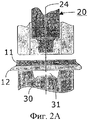
фиг.2A - первый этап клинчевания, причем оба переходных участка пуансона не показаны;figa - the first stage of clinching, and both transitional section of the punch is not shown;
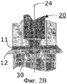
фиг.2B - второй этап клинчевания, причем оба переходных участка пуансона не показаны;figv - the second stage of clinching, and both transitional section of the punch is not shown;
фиг.2C - третий этап клинчевания, причем оба переходных участка пуансона не показаны;figs - the third stage of clinching, and both transitional sections of the punch are not shown;
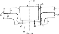
фиг.3A - разрез двух соединенных клинчеванием металлических деталей;figa - section of two connected by clinching metal parts;
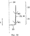
фиг.3B - частичный разрез или детализация одного участка инструмента для клинчевания;figv is a partial section or detail of one section of the tool for clinching;
фиг.4A - разрез двух соединенных клинчеванием металлических деталей и металлической отдельной части и части инструмента для клинчевания (не заявлен), причем пуансон имеет диаметр 12 мм;figa is a section of two connected by clinching metal parts and a metal separate part and part of the tool for clinching (not declared), and the punch has a diameter of 12 mm;
фиг.4B - разрез двух соединенных клинчеванием металлических деталей и части инструмента для клинчевания (не заявлен), причем пуансон имеет диаметр 14 мм;figv - section of two connected by clinching metal parts and parts of the tool for clinching (not declared), and the punch has a diameter of 14 mm;
фиг.4C - разрез двух соединенных клинчеванием металлических деталей и части инструмента для клинчевания (не заявлен), причем пуансон имеет диаметр 20 мм;figs is a section of two connected by clinching metal parts and parts of the tool for clinching (not declared), and the punch has a diameter of 20 mm;
фиг.5A, 5B - разрезы пуансона, схематично;figa, 5B - sections of the punch, schematically;
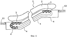
фиг.6 - вид сбоку эскалатора или движущегося тротуара с решетчатой или несущей конструкцией;6 is a side view of an escalator or moving sidewalk with a trellised or supporting structure;
фиг.7 - вид сбоку части несущей конструкции с двойными клинч-соединениями;7 is a side view of part of the supporting structure with double clinch connections;
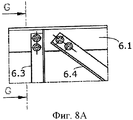
фиг.8A - вид части несущей конструкции с двойными клинч-соединениями;figa is a view of a part of the supporting structure with double clinch connections;
фиг.8B - разрез G-G двойных клинч-соединений;figv - section G-G double clinch connections;
фиг.9 - вид части другой несущей конструкции со сварными соединениями;Fig.9 is a view of a part of another supporting structure with welded joints;
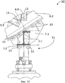
фиг.10 - вид части средней опоры для несущей конструкции с клинч-соединениями.10 is a view of a portion of a middle support for a supporting structure with clinch joints.
В рамках данной заявки речь идет о клинчевании без доли резания. Этот вид клинчевания является процессом соединения с деформированием. Соединение деталей реализуется только посредством прохода в сочетании с глухой прошивкой и последующей осадкой. Основной идеей разработки этого способа без доли резания является, прежде всего, стремление к повышенной жесткости соединения вследствие большего сцепления материалов.In the framework of this application we are talking about clinching without a share of cutting. This type of clinching is a process of joining with deformation. The connection of parts is realized only through a passage in combination with a blind flashing and subsequent settlement. The main idea of the development of this method without a fraction of cutting is, first of all, the desire for increased rigidity of the connection due to greater adhesion of materials.
Принцип изобретения схематично показан на фиг.1. Показаны две металлические детали 11, 12, соединенные между собой посредством клинч-соединения 13. Часть инструмента 20, называемая здесь пуансон, изображена над клинч-соединением 10 или точкой клинча.The principle of the invention is shown schematically in FIG. Two
Инструмент 20 для клинчевания содержит пуансон и ответный инструмент 30, который может быть выполнен в виде матрицы или неподвижного упора. Пуансон выполнен вращательно-симметричным по отношению к оси 24 его вращения. Пуансон имеет расположенную концентрично оси 24 вращения боковую сторону 25 с углом W. По отношению к торцевой поверхности 23 пуансона у боковой стороны 25 различают примыкающий к торцевой поверхности 23 нижний переходный участок 21 боковой стороны 25 с углом W1 и ее верхний переходный участок 22 с углом W2. Оба переходных участка 21, 22 переходят друг в друга. При этом, как показано на фиг.1, 3В, 5А, они могут переходить друг в друга неплавно и иметь разные углы W1, W2 боковой стороны 25. Соединяемые металлические детали 11, 12 (например, стальная балка толщиной t1 и лист толщиной t2, причем t1>t2) вдавливаются пуансоном, как при чеканке или осадке с пластическим деформированием в лунку, или выемку, или полость, или деформирующее пространство 31 матрицы 30 (фиг.2А-2С). За счет специального выполнения лунки, или выемки, или полости, или деформирующего пространства 31 возникает клинч-соединение 13, которое имеет форму, схожую с кнопкой, или точкой осадки, или точкой чеканки. За счет клинч-соединения 13 металлические детали 11, 12 соединены между собой с геометрическим и силовым замыканием, как это схематично показано на фиг.1, 2С, 3A и 4.The clinching
На фиг.2А-2С показаны три ступени образования клинч-соединения 13 без доли резания с жесткой матрицей 30. Для простоты обе металлические детали 11, 12 изображены одинаковой толщины.On figa-2C shows the three stages of the formation of
На фиг.2А показано, что детали 11, 12 прикладываются друг к другу, т.е. позиционируются друг на друге. Затем они выверяются по отношению друг к другу, например посредством шаблона, после чего кладутся на обрабатывающую поверхность служащей в качестве ответного инструмента матрицы 30. На фиг.2В видно, что пуансон инструмента 20 опустился и частично уже погрузился в детали 11, 12. Под действием высокого давления пуансона детали 11, 12 деформируются, и материал «течет» в лунку, или выемку, или полость, или деформирующее пространство 31 матрицы 30. Вдавливание или погружение пуансона происходит до тех пор, пока нижняя сторона 14 детали 12, в основном, не будет прилегать к дну выемки, или полости, или деформирующего пространства, или лунки 31 матрицы 30. На следующем этапе пуансон поднимается (этот этап, в основном, соответствует изображенной на фиг.1 ситуации).On figa shows that the
Согласно изобретению при отделении используется преимущественно съемник или прижим 40, который облегчает отделение пуансона после деформирования деталей 11, 12. Такой съемник или прижим 40 предпочтителен особенно в том случае, если пуансон вследствие возникающих при деформировании сил и деформаций материала защемляется в клинч-соединении 13. Съемник 40 опирается (как бы) на поверхность 15 верхней или со стороны пуансона детали 11 во время отвода пуансона. Применив настоящее изобретение, специалист может, разумеется, реализовать вместо съемника со стороны пуансона также пуансон со стороны матрицы.According to the invention, a puller or clamp 40 is mainly used in the separation, which facilitates the separation of the punch after deformation of the
Предпочтительно, соединяемые детали 11, 12 прижаты к матрице 30 прижимом, обозначенным на фиг.1 поз.41. Инструмент 20 содержит нажимной цилиндр (например, гидроцилиндр, пневмоцилиндр, пневмогидравлический цилиндр, серврэлектрический цилиндр), который вызывает подачу пуансона в направлении детали 11, а затем 12. На первом этапе подачи пуансон опускается (фиг.2А), а затем происходит этап погружения, на котором пуансон погружается в детали 11, 12, осаживая и деформируя их (фиг.2B, 2C). Вслед за этим происходит этап, называемый обратным ходом пуансона (фиг.1). После этого (частично) готовый, или соединенный, или собранный стальной конструктивный элемент может быть извлечен, или могут быть выполнены другие клинч-соединения.Preferably, the
Вследствие давления осадки во время погружения происходит поперечное течение материала деталей 11, 12, в результате чего матрица 30 с лункой, или выемкой, или полостью, или деформирующим пространством 31, например в виде кольцевой канавки, в основном, или полностью заполняется, и в детали 12 со стороны матрицы создается поднутрение f детали 11 со стороны пуансона (фиг.3A). Для оценки клинч-соединения 13, как показано на фиг.3A, поднутрение f и толщина tn шейки являются самыми важными или самыми значительными, поскольку несущая способность клинч-соединения 13 находится в прямой корреляции с этими параметрами. Оба этих параметра очень важны для стабильности и прочности стальных конструктивных элементов. Типичное значение поднутрения f составляет 0,5 мм, а типичное значение толщины tn шейки - 1,5 мм.Due to the upsetting pressure during immersion, a transverse flow of material of
Клинч-соединение 13 и детали 11, 12 могут быть дополнительно охарактеризованы следующими данными: di - внутренний диаметр соединяющего элемента или пуансона, h - высота выступающей части, tb2 - остаточная толщина дна детали 12 со стороны матрицы, tb1 - остаточная толщина дна детали 11 со стороны пуансона, t2 - толщина детали со стороны матрицы, t1 - толщина детали со стороны пуансона, tt - общая толщина деталей.
Были проведены различные испытания и эксперименты для оптимизации и видоизменения известного процесса клинчевания так, чтобы можно было соединять между собой в стальной конструктивный элемент даже детали 11, 12 толще 4 мм без возникновения слишком высоких усилий защемления. Было проведено имитационное моделирование, а затем были изготовлены различные инструменты и осуществлены испытания по соединению, чтобы можно было сравнить полученные (во время эксперимента) сечения, соединительные и прижимные усилия с эталонными значениями от имитационного моделирования. Основой исследований по расчету инструмента служили принципы расчета инструмента для клинчевания без доли резания с жесткой матрицей 30.Various tests and experiments have been carried out to optimize and modify the known clinching process so that even
Первые исследования показали, что для изготовления клинч-соединения 13 при малом диаметре пуансона (D2=12 мм или 14 мм) приходится прикладывать соединительные усилия 400-510 кН, а при большем диаметре пуансона (D2=20 мм) - около 670 кН (в обоих случаях включая прижимное усилие). Эти результаты лежат сами по себе в пределах ожидаемого. (Однако несмотря на смазку инструмента происходило сильное защемление пуансона в детали.)The first studies showed that for the manufacture of
Более подробные исследования защемления пуансона показали, что оно вызвано радиальным напряжением, воздействующим на боковую сторону пуансона. Оказалось, что высокие радиальные напряжения возникают особенно на верхнем переходном участке 22.More detailed studies of the punch pinched have shown that it is caused by radial stress acting on the side of the punch. It turned out that high radial stresses occur especially in the
На следующем этапе оптимизации геометрия пуансона была целенаправленно изменена так, что на его боковую сторону 25 воздействует меньшее радиальное напряжение. Вследствие того, что в первых вариантах выполнения инструмента значение толщины tn шейки и значение поднутрения f в случае пуансонов диаметрами D2=12 мм и D2=14 мм были почти равны, была предпринята дальнейшая оптимизация. При этом были проведены также исследования с деталями разной общей толщины tt и с деталями 11, 12, разной толщины t1, t2. Оказалось, что стандартные пуансоны не только имеют сильную тенденцию к защемлению в случае перехода к общим толщинам tt>8 мм, но и в зоне между деталями 11, 12 образуется полость Х (фиг.4С). Эта полость Х нарушает и уменьшает прочность соответствующего клинч-соединения 13 и стабильность всего стального конструктивного элемента.At the next stage of optimization, the geometry of the punch was purposefully changed so that a smaller radial stress acts on its
Различные этапы оптимизации позволили сделать вывод о том, что выполнение боковых сторон пуансона оказывает непосредственное влияние на его защемление и образование полости X. Чтобы уменьшить или полностью устранить оба этих негативных эффекта, были разработаны пуансоны, по меньшей мере, частично конической формы. При подходящем выборе соответствующего угла W, W1, W2 боковых сторон удалось уменьшить или полностью предотвратить защемление без образования заметной полости. Оказалось, что оба этих эффекта лишь частично взаимосвязаны, а частично даже противоположны друг другу. За счет выбора подходящего диапазона углов удалось минимизировать оба эффекта. Этим была создана основа для клинчевания толстых листов в стабильные стальные конструктивные элементы с клинч-соединениями 13.Various stages of optimization led to the conclusion that the execution of the lateral sides of the punch directly affects its pinching and the formation of cavity X. In order to reduce or completely eliminate both of these negative effects, punches of at least partially conical shape were developed. With a suitable choice of the corresponding angle W, W1, W2 of the sides, it was possible to reduce or completely prevent pinching without the formation of a noticeable cavity. It turned out that both of these effects are only partially interconnected, and partially even opposite to each other. By choosing a suitable range of angles, both effects were minimized. This created the basis for clinching thick sheets into stable steel structural elements with clinch joints 13.
Во время изображенных на фиг.4А-4С и описанных ниже исследований пуансон имеет постоянный угол W боковой стороны, составляющий 5°, т.е. D1<D2. Другими словами, по меньшей мере, та часть пуансона, которая при погружении вступает в контакт с деталями 11, 12, сужается вниз (т.е. в направлении конца пуансона со стороны деталей).During the studies shown in FIGS. 4A-4C and described below, the punch has a constant side angle W of 5 °, i.e. D1 <D2. In other words, at least the part of the punch that, when immersed, comes into contact with the
Некоторые аспекты различных исследований представлены на фиг.4А-4С, поскольку они аналогичным образом относятся к заявленным пуансонам. Изображен характер течения деталей 11, 12 при использовании пуансонов разных диаметров. На фиг.4А показано, как деформируются две детали 11, 12, если пуансон имеет диаметр 12 мм, на фиг.4В - диаметр 14 мм, а на фиг.4С - диаметр 20 мм. На всех фигурах показан момент перед обратным ходом пуансона.Some aspects of various studies are presented in FIGS. 4A-4C, since they relate similarly to the claimed punches. The flow pattern of
С помощью фиг.4А-4С можно видеть, что диаметр D2 пуансона оказывает влияние на поперечное течение материалов или деталей. В случае пуансона диаметром 12 мм материал детали 12 течет в образованную лункой или выемкой 31 полость не полностью, как это видно в зоне Y. В случае 14-миллиметрового пуансона происходит хорошее «заполнение» лунки или выемки 31. При использовании пуансона диаметром 20 мм между деталями 11, 12 возникает полость Х (фиг.4С).Using figa-4C, you can see that the diameter D2 of the punch affects the transverse flow of materials or parts. In the case of a punch with a diameter of 12 mm, the material of
Как показали различные исследования, диаметр пуансона является лишь одним из различных параметров, оказывающих прямое влияние на процесс клинчевания и прочность клинч-соединения. Оказалось, что при клинчевании толстых деталей с tt>8 мм выполнение боковой стороны 25 играет особенно важную и значительную роль.As various studies have shown, the diameter of the punch is only one of various parameters that have a direct effect on the clinching process and the strength of the clinch connection. It turned out that when clinching thick parts with tt> 8 mm, the execution of the
В соответствии с этим настоящее изобретение характеризуется тем, что пуансон, погружаемый при деформировании в детали 11, 12, имеет коническую форму. Коническая форма пуансона простирается, по меньшей мере, по части (обозначенной как переходные участки 21, 22) той его длины L, которая погружается или вдавливается в детали 11, 12. Коническая форма возникает за счет того, что боковая сторона 25 пуансона (фиг.3В), по меньшей мере, на нижнем переходном участке 21 к торцевой поверхности 23 выполнена конической и имеет угол W1, который меньше или равен 10°, преимущественно меньше или равен 5°. Как показано на фиг.1 и 5А, угол W2 боковой стороны 25 на верхнем переходном участке 22 преимущественно равен 0° или также преимущественно меньше или равен 5° (примеры на фиг.4А-4С и 5В).In accordance with this, the present invention is characterized in that the punch, immersed during deformation in the
Особенно хорошо зарекомендовали себя пуансоны диаметром D2 10-20 мм и с углами W1, W2 боковой стороны, причем первый угол W1 переходит во второй угол W2 и меньше или равен 10° и преимущественно меньше или равен 5°, а второй угол W2 меньше или равен 2°, преимущественно составляет 0-1°. При этом (нижний) переходной участок 21 имеет первый угол W1 к торцевой поверхности 23 (т.е. в зоне конца пуансона со стороны деталей 11, 12), а выступающий наружу (верхний) переходной участок 22 (т.е. на участке пуансона со стороны инструмента), или обращенный от деталей 11, 12, имеет второй угол W2.Punches with a diameter of D2 of 10-20 mm and with corners W1, W2 of the side are especially well established, with the first angle W1 turning into the second angle W2 and less than or equal to 10 ° and mostly less than or equal to 5 °, and the second angle W2 less than or equal 2 °, mainly 0-1 °. In this case, the (lower)
Это выполнение конических пуансонов имеет заметно меньшую тенденцию к защемлению, и не образуется никаких полостей Х (или образуются слабо выраженные полости). Преимущество меньшего радиального напряжения и тем самым меньшей тенденции к защемлению реализуется, однако, посредством возникновения полости Х между деталями 11, 12. Это значит, что углы W, W1, W2 нельзя выбирать произвольно, поскольку иначе полость Х станет слишком большой, а прочность клинч-соединения - слишком низкой.This embodiment of conical punches has a markedly less tendency to pinch, and no X cavities are formed (or weakly expressed cavities are formed). The advantage of a lower radial stress and thereby a smaller tendency to pinch is realized, however, by creating a cavity X between the
Идеальными являются варианты пуансона, в которых вызванное углом уменьшение боковой стороны не слишком большое, поскольку при слишком большом уменьшении боковой стороны радиально направленное давление на детали 11, 12 станет слишком низким, в результате чего уменьшится поперечное течение материалов или деталей.Punch variants are ideal in which the angle-induced side-side reduction is not too large, since if the side-side is too large, the radially directed pressure on the
Указанные значения углов W, W1, W2 зарекомендовали себя также потому, что изготовленные с этими пуансонами клинч-соединения имеют аналогичные сопоставимые значения толщины tn шейки и поднутрения f, что и в случае стандартных и распространенных цилиндрических пуансонов. Это свидетельствует о сопоставимой идентичной прочности на растяжение соответствующего клинч-соединения 13.The indicated values of the angles W, W1, W2 also proved themselves because clinch joints made with these punches have similar comparable values of neck thickness tn and undercut f, as in the case of standard and common cylindrical punches. This indicates a comparable identical tensile strength of the
Коническая форма пуансона простирается, по меньшей мере, по переходным участкам 21, 22 той его длины L, которая погружается в детали 11, 12. Эта длина L в случае деталей общей толщиной tt>8 мм может быть рассчитана следующим образом: 0,3 tt≤L≤2 tt. Это значит, что конические переходные участки 21, 22 соответствуют значению между тремя десятыми общей толщины tt деталей и их двукратной общей толщиной tt.The conical shape of the punch extends at least along the
Различные формы пуансонов поясняются ниже с помощью фиг.1 и 5А.Various forms of punches are explained below using FIGS. 1 and 5A.
Прочность, достигаемая с пуансонами, например с пуансоном диаметром 12 мм и углом боковой стороны 5-0° (вариант 2, фиг.5А), составляет, в среднем, соответственно 50 и 55 кН. При особенно тщательно подобранных условиях растягивающее усилие составляет даже около 58 кН с лишь незначительным разбросом в несколько процентов.The strength achieved with punches, for example with a punch with a diameter of 12 mm and a side angle of 5-0 ° (
Для расчета усилия съема (усилия съемника 40) следует учесть два критерия. Во-первых, усилие съема или усилие съемника должно быть больше усилия защемления пуансона. Это значение, разумеется, сильно зависит от применяемой геометрии пуансона, как было сказано выше, а также от смазки или покрытия инструментов. Максимальные усилия выталкивания в 30-40 кН привели к очень надежным результатам. При оптимальном выполнении углов боковой стороны или конусности пуансона достаточно усилий выталкивания 25 кН. Для пуансона с углом боковой стороны 5-0° (вариант 2, фиг.5А) можно принять во внимание даже дальнейшее уменьшение усилия выталкивания, поскольку в этом случае никогда не произойдет защемления пуансона.To calculate the removal force (
В одном особенно предпочтительном варианте съемник 40 служит одновременно прижимом 41 и рассчитан так, что детали 11, 12 испытывают минимальное деформирование для минимально возможного коробления или для его предотвращения.In one particularly preferred embodiment, the
Пуансоны и инструменты, или машины для клинчевания, содержащие соответствующие пуансоны, позволяют изготавливать особенно стабильные и обладающие высокой несущей способностью 1 стальные конструктивные элементы самым простым, легким, рентабельным и надежным образом. Расходы на эти стальные конструктивные элементы с клинч-соединениями 13 ниже расходов на сварные, клепаные или свинченные соединения. Расходы на комбинированный материал для стальных конструктивных элементов с клинч-соединениями 13 равны нулю. Кроме того, до минимума сокращено рабочее время.Punches and tools, or clinching machines, containing the corresponding punches, make it possible to produce particularly stable and highly load-bearing 1 steel structural elements in the simplest, easiest, most cost-effective and reliable way. The costs of these steel structural elements with
На фиг.6 при виде сбоку изображен эскалатор 1. Он содержит балюстраду 2 с движущимся поручнем и бесконечную цепь со ступенями 3. Под балюстрадой 2 эскалатора или движущегося тротуара расположена стальная конструкция 4, выполненная так, что она перекрывает промежуток или пролет между двумя этажами E1, E2 и несет элементы, или детали, или узлы эскалатора 1 или движущегося тротуара.In Fig. 6, a side view shows the escalator 1. It contains a
Эта стальная конструкция 4 должна отвечать самым строгим требованиям и потому дорога и сложна в изготовлении. Согласно изобретению используются каркасные стальные конструктивные элементы или, как показано на фиг.7, каркасный несущий элемент 5. Такие каркасные стальные конструктивные элементы или такой каркасный несущий элемент 5 может содержать две проходящие в продольном направлении стальные или профильные балки 6.1, 6.2. Особенно предпочтительны стальные балки L-образного, I-образного или U-образного профиля, а также трубы или фасонные трубы. Эти обе стальные балки 6.1, 6.2 соединяются между собой посредством определенного числа пластин (Flachblechen), или листового железа, или плоских листов (Blechprofilen), или стальных профилей 6.3, 6.4. Они закреплены посредством одного, или двух, или трех, или более клинч-соединений 13 с каждой из этих стальных или профильных балок 6.1, 6.2 и образуют стабильную каркасную раму, или каркасную несущую стенку, или каркасный несущий элемент.This
Как видно на фиг.7, пластины, или листовое железо, или стальные профили, или листы располагают обычно так, что каждая вертикальная стойка или каждый подкос 6.3 перемежается с наклонным подкосом или диагональю 6.4. Клинч-соединения 13 обозначены кружками А.As can be seen in Fig.7, plates, or sheet metal, or steel profiles, or sheets are usually arranged so that each vertical stand or each strut 6.3 is interspersed with an inclined strut or diagonal 6.4.
На фиг.8А, 8В изображены особенности стального конструктивного элемента 5. Видны одна из стальных балок 6.1 и две пластины, или листовое железо, или плоские листы, или стальные профили 6.3, 6.4. В данном примере стальная балка 6.1 представляет L-образную балку или уголок толщиной t1 более 4 мм, а подкосы или подкосы и диагонали представляют собой согнутые под углом плоские листы, или листовое железо, или стальные профили, или стальные конструктивные профили 6.3, 6.4 толщиной t2 болеет 3 мм. На фиг.8В изображен разрез двух расположенных рядом друг с другом клинч-соединений 13. Соответствующее соединение называется также двойным клинч-соединением.On figa, 8B shows the features of the steel
Согласно изобретению особенно предпочтительными считаются стальные конструктивные элементы, в которых между собой соединены разнотолщинные металлические детали (например, продольная или профильная балка 6.1 и плоские листы, или стальные профили, или стальные конструктивные профили 6.3, 6.4), причем клинч-соединения 13 выполняются преимущественно с более толстой стороны деталей. Это значит, что пуансон погружается со стороны более толстой детали, а клинч-соединение образуется на противоположной стороне (фиг.8В). Другими словами, предпочтительны клинч-соединения, у которых более толстый материал в результате локального деформирования в более тонкий материал за счет поперечного течения деформируется в прочное соединение.According to the invention, steel structural elements are considered to be particularly preferred, in which different thickness metal parts are connected to each other (for example, a longitudinal or profile beam 6.1 and flat sheets, or steel profiles, or steel structural profiles 6.3, 6.4), and clinch
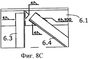
На фиг.8С для сравнения изображена часть каркаса или каркасной несущей рамы, детали 6.1, 6.2, 6.3 которой были сварены между собой посредством пяти или шести сварных соединений. Очевидно, что такие сварные соединения сложны в изготовлении.On figs for comparison shows part of the frame or frame supporting frame, parts 6.1, 6.2, 6.3 of which were welded together by means of five or six welded joints. Obviously, such welded joints are difficult to manufacture.
На фиг.9 изображен другой вариант выполнения изобретения. Здесь для изготовления стального конструктивного элемента используются единичные клинч-соединения. Соответствующее соединение называется одинарным клинч-соединением.Figure 9 shows another embodiment of the invention. Here, single clinch joints are used to make the steel structural member. The corresponding connection is called a single clinch connection.
На фиг.10 изображен еще один вариант выполнения изобретения. Здесь, например, для изготовления (средней или центральной) опоры 51 в виде стальной конструкции также используются клинч-соединения 13. Эта опора 51 может быть частью стального конструктивного элемента 50, 5 для использования в эскалаторостроении. Стальной профиль 7.1 расположен, как схематично показано, на нижнем стальном профиле 7.2. Оба стальных профиля соединены между собой посредством клинч-соединений 13. Кроме того, также профили 7.1 и 7.3 могут быть склинчены с профилем 6.2 и иметь одно или несколько клинч-соединений 13. На стальном профиле 7.1 расположена продольная или профильная балка 6.2. На этой продольной или профильной балке 6.2 посредством клинч-соединений 13 закреплены несколько пластин, или листовое железо, или плоские листы, или стальные профили 6.5, 6.6.Figure 10 shows another embodiment of the invention. Here, for example, clinch
Согласно изобретению могут изготавливаться также стальные конструктивные элементы, являющиеся частью лифтовой установки. Так, например, деталь 11 может быть опорным, или несущим, или фиксирующим элементом кабины. Тогда деталь 12 представляет собой пластину, или листовое железо, или плоский лист, или стальной профиль, закрепленный на опорном, или несущем, или фиксирующем элементе посредством одного, или двух, или трех, или более клинч-соединений 13. Так, например, рама или ловильная рама кабины может изготавливаться из стабильных стальных балок 11, имеющих несколько подкосов из листов или стальных профилей. Эти подкосы соединены со стальными балками посредством клинч-соединений. Кроме того, решетка лебедки, или приводная решетка, или приводная балка, или станина машины, или станина лебедки, или рама машины могут быть соединены со стальными профилями или листами посредством клинч-соединений.According to the invention can also be made of steel structural elements that are part of an elevator installation. So, for example,
Деталь 11 может быть также опорным или рамным элементом противовеса, соответственно рамы противовеса или корзины противовеса лифтовой установки. В этом случае деталь 12 представляет собой пластину, или листовое железо, или плоский лист, или стальной профиль, закрепленный на опорном или рамном элементе посредством одного, или двух, или трех, или более клинч-соединений 13.
С помощью пуансона 20 можно выполнять рядом друг с другом также два клинч-соединения 13 (фиг.8А, 8В), чтобы дополнительно повысить прочность на растяжение и срез. В этом случае оказалось, что прочность на растяжение удалось повысить до значений, которые почти вдвое больше, чем при одинарном клинч-соединении 13. Образцы выдерживали нагрузку, в среднем, около 118 кН.Using the
Предпочтительно инструмент 20 содержит два одинаковых пуансона, которые расположены рядом друг с другом и способны соединять детали 11, 12 посредством двух клинч-соединений. Здесь с помощью движений подачи и погружения можно выполнять рядом друг с другом одновременно два клинч-соединения. Пример соответствующего двойного клинч-соединения показан на фиг.8А, 8В. В данном примере показано, что толстую стальную профильную балку 11, 6.1 (первая металлическая деталь) можно соединить с более тонким листом, или листовым железом, или стальным профилем, или стальным листом 12, 6.3, 6.4 (вторая металлическая деталь) посредством двух лежащих рядом друг с другом клинч-соединений 13.Preferably, the
Согласно изобретению клинч-соединения 13 можно выполнять без доли резания также с открывающейся матрицей. При этом подпружиненно установленные пластины матрицы по окончании процесса погружения пуансона за счет радиального течения материала деталей под ним отжимаются наружу, что обеспечивает выполнение поднутрения.According to the invention, clinch
Помимо преимуществ традиционного клинчевания можно применять также безматричное клинчевание, которое благодаря своему специальному функциональному принципу обладает следующими преимуществами.In addition to the advantages of traditional clinching, you can also use bezmatrichnoe clinching, which, due to its special functional principle, has the following advantages.
- Смещение между (соединительным) пуансоном и ответным инструментом (неподвижный упор) не ухудшает качества соединения 13. За счет этого снижаются требования к точности соединительной машины.- The offset between the (connecting) punch and the reciprocal tool (fixed stop) does not impair the quality of the
- Отпадают отнимающие много времени наладочные работы.- Time-consuming setup work disappears.
- Износ уменьшается, а надежность процесса возрастает, поскольку на кромке матрицы больше не возникают сколы.- Depreciation decreases, and process reliability increases, since chips no longer occur on the edge of the matrix.
- Для всех задач соединения можно использовать один и тот же неподвижный упор. В смене матрицы при смене задачи соединения, как при традиционном клинчевании, больше нет необходимости.- For all connection tasks you can use the same fixed stop. In changing the matrix when changing the connection task, as with traditional clinching, there is no longer a need.
- Соединения 13 более плоские и мешают меньше, чем соединения, выполненные посредством традиционного клинчевания.- Compounds 13 are flatter and interfere less than joints made by conventional clinching.
- Изменение толщины листа возможно без смены матрицы и позволяет экономить дорогостоящее рабочее время.- Changing the sheet thickness is possible without changing the matrix and allows you to save expensive working time.
- Изменение подбора материала происходит без затрат.- Changing the selection of material occurs without cost.
- Безматричное клинчевание позволяет повысить число клинч-соединений или соединительных точек на каждый инструментальный комплект или на каждый (соединительный) пуансон.- Tapeless clinching allows you to increase the number of clinch connections or connecting points for each tool kit or for each (connecting) punch.
Claims (30)
Applications Claiming Priority (2)
| Application Number | Priority Date | Filing Date | Title |
|---|---|---|---|
| EP07102275.0 | 2007-02-13 | ||
| EP07102275 | 2007-02-13 |
Publications (2)
| Publication Number | Publication Date |
|---|---|
| RU2009134108A RU2009134108A (en) | 2011-03-20 |
| RU2456110C2 true RU2456110C2 (en) | 2012-07-20 |
Family
ID=38054244
Family Applications (1)
| Application Number | Title | Priority Date | Filing Date |
|---|---|---|---|
| RU2009134108/02A RU2456110C2 (en) | 2007-02-13 | 2008-02-08 | Method of producing steel bearing-capacity structural element by clinching metal parts, clinching tool and steel structural element |
Country Status (25)
| Country | Link |
|---|---|
| US (1) | US8555479B2 (en) |
| EP (1) | EP2117747B1 (en) |
| JP (1) | JP5437080B2 (en) |
| KR (1) | KR20090108719A (en) |
| CN (1) | CN101610860B (en) |
| AT (1) | ATE506126T1 (en) |
| AU (1) | AU2008215091B2 (en) |
| BR (1) | BRPI0807542A2 (en) |
| CA (1) | CA2675958C (en) |
| DE (1) | DE502008003275D1 (en) |
| DK (1) | DK2117747T3 (en) |
| ES (1) | ES2365373T3 (en) |
| HR (1) | HRP20110533T8 (en) |
| IL (1) | IL199818A (en) |
| MX (1) | MX2009008328A (en) |
| MY (1) | MY153259A (en) |
| NZ (1) | NZ578769A (en) |
| PL (1) | PL2117747T3 (en) |
| PT (1) | PT2117747E (en) |
| RU (1) | RU2456110C2 (en) |
| SI (1) | SI2117747T1 (en) |
| TW (1) | TWI403370B (en) |
| UA (1) | UA99606C2 (en) |
| WO (1) | WO2008098390A1 (en) |
| ZA (1) | ZA200905512B (en) |
Cited By (3)
| Publication number | Priority date | Publication date | Assignee | Title |
|---|---|---|---|---|
| RU2618681C1 (en) * | 2016-01-11 | 2017-05-10 | Федеральное государственное бюджетное образовательное учреждение высшего профессионального образования "Казанский национальный исследовательский технический университет им. А.Н. Туполева-КАИ" (КНИТУ-КАИ) | Assembly method for overlapped metal sheets by clinching |
| RU2621089C2 (en) * | 2012-09-03 | 2017-05-31 | Бвг Бергверк-Унд Вальцверк-Машиненбау Гмбх | Method and device for jointing metal strips |
| RU2709412C1 (en) * | 2017-12-08 | 2019-12-17 | Тойота Дзидося Кабусики Кайся | Connecting structure |
Families Citing this family (24)
| Publication number | Priority date | Publication date | Assignee | Title |
|---|---|---|---|---|
| DE102009036185A1 (en) * | 2009-08-05 | 2011-02-17 | Peter Paul Payr | Method for and devices with connection of two material layers |
| DE102010010185A1 (en) * | 2010-03-03 | 2011-09-08 | Airbus Operations Gmbh | Component connecting arrangement, particularly for large-area flat components, of aircraft, has plate part with attachment part, where plate part and attachment part are connected with each other in boundary areas |
| CN101943258A (en) * | 2010-09-21 | 2011-01-12 | 江苏德科汽车科技有限公司 | Belt pulley for tensioner and manufacturing method thereof |
| CN101934339B (en) * | 2010-09-21 | 2012-10-17 | 上海交通大学 | Ring electroplastic rivetless riveting device |
| DE202011000731U1 (en) | 2011-03-30 | 2011-06-01 | Schmitz Cargobull AG, 48341 | Profile carrier for a vehicle chassis and utility vehicle chassis with such a profile carrier |
| WO2012146793A1 (en) * | 2011-04-29 | 2012-11-01 | Geo-Hidrol, S.A. | Framework for structural use |
| US9259774B2 (en) * | 2011-05-03 | 2016-02-16 | GM Global Technology Operations LLC | Clinching method and tool for performing the same |
| US9669453B2 (en) | 2013-10-14 | 2017-06-06 | Ford Global Technologies, Llc | Expandable clinch joint punch |
| US20150143685A1 (en) * | 2013-11-22 | 2015-05-28 | Ford Global Technologies, Llc | Clinch Punch with Elastomeric Tip |
| EP2915607B1 (en) | 2014-03-04 | 2019-05-08 | Fontaine Holdings NV | Galvanized metal objects and their manufacturing process |
| CN105673641A (en) * | 2014-11-22 | 2016-06-15 | 苏州耀洲金属制品有限公司 | Finished product bracket |
| FR3033215B1 (en) * | 2015-02-26 | 2017-02-24 | Valeo Vision | POWER SOCKET FOR VEHICLE COCKPIT |
| CN104953438B (en) * | 2015-05-11 | 2017-03-22 | 株洲南车时代电气股份有限公司 | Positioning guiding riveter for busbars |
| EP3109196A1 (en) | 2015-06-25 | 2016-12-28 | Thyssenkrupp Elevator Innovation Center, S.A. | Escalator/moving walkway modular truss and method of assembling an escalator/moving walkway modular truss |
| ES2900448T3 (en) | 2015-06-25 | 2022-03-17 | Tk Elevator Innovation Center S A | Modular truss for escalators/moving walkways and assembly procedure of modular truss for escalators/moving walkways |
| CN105108025B (en) * | 2015-08-28 | 2018-06-26 | 广西汽车集团有限公司 | Sleeving and riveting machine is applied mechanically in a kind of riveting |
| WO2017055163A1 (en) * | 2015-09-29 | 2017-04-06 | Inventio Ag | Method for installing a support structure for a passenger transport system in a construction |
| DE102015224549A1 (en) * | 2015-12-08 | 2017-06-08 | Thyssenkrupp Ag | Escalator or moving walkway support construction and method of manufacturing at least one subsegment of an escalator or moving walkway support structure |
| WO2018209001A1 (en) * | 2017-05-09 | 2018-11-15 | Penn Engineering & Manufacturing Corp. | Fastener and installation method for very thin sheets |
| EP4105946B1 (en) * | 2017-11-15 | 2024-01-03 | Nippon Telegraph and Telephone Corporation | Elastic wiring and method for producing elastic wiring |
| PL232925B1 (en) * | 2018-06-20 | 2019-08-30 | Politechnika Wroclawska | Method for increasing mechanical strength of the redrawn point-to-point connectors |
| CN111659805B (en) * | 2020-06-12 | 2021-05-07 | 中南大学 | Continuous two-stroke neck-reinforced riveted connection device and method |
| EP4424625A1 (en) * | 2023-03-03 | 2024-09-04 | Otis Elevator Company | Elevator guide rail |
| IT202300014928A1 (en) * | 2023-07-17 | 2025-01-17 | Oli Sist Sanitarios S A | SANITARY WARE INSTALLATION STRUCTURE AND ITS MANUFACTURING METHOD |
Citations (3)
| Publication number | Priority date | Publication date | Assignee | Title |
|---|---|---|---|---|
| SU1286099A3 (en) * | 1984-03-22 | 1987-01-23 | Герд Юрген Экольд и Ханс Маасе (DE) | Method of joining two sheets and device for effecting same |
| SU1761351A1 (en) * | 1990-02-28 | 1992-09-15 | Московский институт стали и сплавов | Method of connecting two intermediate sheet products of different thickness and device therefor |
| RU93053994A (en) * | 1992-12-05 | 1996-07-20 | Экольд ГмбХ унд Ко, КГ | METHOD AND DEVICE FOR CONNECTING METAL SHEETS DEPENDED ON OTHER TO OTHERS BY LOCAL PLASTIC DEFORMATION |
Family Cites Families (19)
| Publication number | Priority date | Publication date | Assignee | Title |
|---|---|---|---|---|
| US3555831A (en) * | 1968-09-16 | 1971-01-19 | Texaco Inc | Composite foundation member and method |
| US4803767A (en) * | 1986-08-29 | 1989-02-14 | Lamb Robo | Clinching tool |
| DE3923182A1 (en) * | 1989-07-13 | 1991-01-24 | Fraunhofer Ges Forschung | DEVICE FOR CONNECTING PLATE-SHAPED COMPONENTS |
| US5528815A (en) * | 1990-04-03 | 1996-06-25 | Webb; Edward L. T. | Clinching tool for sheet metal joining |
| US5305517A (en) * | 1991-09-23 | 1994-04-26 | Schleicher Louis C | Apparatus for forming clinch joints |
| DE9114122U1 (en) * | 1991-11-13 | 1993-04-01 | Eckold GmbH & Co KG, 3424 St. Andreasberg | Device for joining sheet metal parts |
| DE4240970A1 (en) * | 1992-12-05 | 1994-06-09 | Eckold Vorrichtung | Process for joining sheet metal, sheet metal parts or plates lying flat on top of one another |
| SE9301097D0 (en) * | 1993-03-31 | 1993-03-31 | Attexor Equipements Sa | A METHOD FOR JOINING TOGETHER TWO OR SEVERAL OVERLAYING SHEET FORMED MEMBERS, AN APPARATUS FOR CARRYING OUT SAID METHOD AND A JOINT RESULTING FROM SAID METHOD |
| US5984563A (en) * | 1994-07-22 | 1999-11-16 | Btm Corporation | Apparatus for joining sheet material and joint formed therein |
| JP3407551B2 (en) * | 1996-07-22 | 2003-05-19 | 日本軽金属株式会社 | Two-member caulking structure, caulking method, and apparatus used therefor |
| JP2780967B2 (en) * | 1996-08-29 | 1998-07-30 | ナショナル住宅産業株式会社 | Work coupling device |
| US6722013B1 (en) * | 1998-03-25 | 2004-04-20 | Tox Pressotechnik Gmbh | Method, tool and punch for joining components to a plate |
| US6217115B1 (en) * | 1999-04-20 | 2001-04-17 | Dura Global Technologies, Inc. | Simplified linkage assembly |
| JP2004520941A (en) * | 2001-05-11 | 2004-07-15 | トックス・プレッソテヒニック・ゲゼルシャフト・ミト・ベシュレンクテル・ハフツング・ウント・コンパニー・コマンディトゲゼルシャフト | Tools for mechanical joining of plates |
| NO20013930A (en) * | 2001-08-13 | 2002-09-09 | Dexion Group Ltd | Method of manufacturing a beam for a storage rack and arrangement of beams for storage racks |
| DE10245604A1 (en) * | 2002-09-30 | 2004-04-15 | Fraunhofer-Gesellschaft zur Förderung der angewandten Forschung e.V. | Method and device for the permanent connection of overlapping, plate-shaped components |
| JP4465581B2 (en) * | 2002-11-29 | 2010-05-19 | 日立オートモティブシステムズ株式会社 | Polymerization plate, polymerization tube, method of overhanging polymerization tube, tool |
| JP4545450B2 (en) * | 2004-02-04 | 2010-09-15 | 三洋機工株式会社 | Metal plate coupling device |
| US20060096075A1 (en) * | 2004-11-08 | 2006-05-11 | Victor Robinson | Clinching tool, die and method for use thereof |
-
2008
- 2008-02-08 ES ES08700551T patent/ES2365373T3/en active Active
- 2008-02-08 AU AU2008215091A patent/AU2008215091B2/en not_active Ceased
- 2008-02-08 UA UAA200908502A patent/UA99606C2/en unknown
- 2008-02-08 MY MYPI20093023A patent/MY153259A/en unknown
- 2008-02-08 PL PL08700551T patent/PL2117747T3/en unknown
- 2008-02-08 NZ NZ578769A patent/NZ578769A/en unknown
- 2008-02-08 MX MX2009008328A patent/MX2009008328A/en active IP Right Grant
- 2008-02-08 AT AT08700551T patent/ATE506126T1/en active
- 2008-02-08 SI SI200830316T patent/SI2117747T1/en unknown
- 2008-02-08 CN CN200880004861.XA patent/CN101610860B/en not_active Expired - Fee Related
- 2008-02-08 KR KR1020097017500A patent/KR20090108719A/en not_active Ceased
- 2008-02-08 PT PT08700551T patent/PT2117747E/en unknown
- 2008-02-08 CA CA2675958A patent/CA2675958C/en not_active Expired - Fee Related
- 2008-02-08 BR BRPI0807542-5A2A patent/BRPI0807542A2/en not_active Application Discontinuation
- 2008-02-08 DK DK08700551.8T patent/DK2117747T3/en active
- 2008-02-08 WO PCT/CH2008/000047 patent/WO2008098390A1/en not_active Ceased
- 2008-02-08 DE DE502008003275T patent/DE502008003275D1/en active Active
- 2008-02-08 EP EP08700551A patent/EP2117747B1/en not_active Not-in-force
- 2008-02-08 ZA ZA200905512A patent/ZA200905512B/en unknown
- 2008-02-08 JP JP2009549355A patent/JP5437080B2/en not_active Expired - Fee Related
- 2008-02-08 HR HR20110533T patent/HRP20110533T8/en unknown
- 2008-02-08 RU RU2009134108/02A patent/RU2456110C2/en not_active IP Right Cessation
- 2008-02-13 TW TW097105010A patent/TWI403370B/en not_active IP Right Cessation
-
2009
- 2009-07-12 IL IL199818A patent/IL199818A/en not_active IP Right Cessation
- 2009-08-12 US US12/539,960 patent/US8555479B2/en not_active Expired - Fee Related
Patent Citations (3)
| Publication number | Priority date | Publication date | Assignee | Title |
|---|---|---|---|---|
| SU1286099A3 (en) * | 1984-03-22 | 1987-01-23 | Герд Юрген Экольд и Ханс Маасе (DE) | Method of joining two sheets and device for effecting same |
| SU1761351A1 (en) * | 1990-02-28 | 1992-09-15 | Московский институт стали и сплавов | Method of connecting two intermediate sheet products of different thickness and device therefor |
| RU93053994A (en) * | 1992-12-05 | 1996-07-20 | Экольд ГмбХ унд Ко, КГ | METHOD AND DEVICE FOR CONNECTING METAL SHEETS DEPENDED ON OTHER TO OTHERS BY LOCAL PLASTIC DEFORMATION |
Cited By (3)
| Publication number | Priority date | Publication date | Assignee | Title |
|---|---|---|---|---|
| RU2621089C2 (en) * | 2012-09-03 | 2017-05-31 | Бвг Бергверк-Унд Вальцверк-Машиненбау Гмбх | Method and device for jointing metal strips |
| RU2618681C1 (en) * | 2016-01-11 | 2017-05-10 | Федеральное государственное бюджетное образовательное учреждение высшего профессионального образования "Казанский национальный исследовательский технический университет им. А.Н. Туполева-КАИ" (КНИТУ-КАИ) | Assembly method for overlapped metal sheets by clinching |
| RU2709412C1 (en) * | 2017-12-08 | 2019-12-17 | Тойота Дзидося Кабусики Кайся | Connecting structure |
Also Published As
Similar Documents
| Publication | Publication Date | Title |
|---|---|---|
| RU2456110C2 (en) | Method of producing steel bearing-capacity structural element by clinching metal parts, clinching tool and steel structural element | |
| RU2464118C2 (en) | Method and tool for riveting thick metal sheets, and applying riveting tool, or apparatus, or instrument | |
| US10053335B2 (en) | Escalator/moving walkway modular truss and method of assembling an escalator/moving walkway modular truss | |
| CN102745580A (en) | Sandwich door panel for automatic lift doors and processing method thereof | |
| CN207714690U (en) | A kind of dismountable steel structure lift shaft | |
| CN106320699A (en) | Quick disassembling and assembling method for truss type formwork bracket system | |
| CN107513936B (en) | Upper-shaped side girder structure and manufacturing method | |
| HK1137963B (en) | Method for clinching thick metal workpieces and use of a clinching tool | |
| CN222593242U (en) | Turnover device of suspended light steel structure landscape bridge | |
| CN214995811U (en) | Shaping auxiliary plate at vertical rod | |
| CN218643921U (en) | Steel bar truss positioning mechanism | |
| CN120100069A (en) | A seismic-resistant aluminum alloy beam-column node with cantilever connection and plate reinforcement | |
| CN120250794A (en) | Aluminum alloy-stainless steel anti-slip connection device fastened by ring groove rivets and its application | |
| CN204310698U (en) | A kind of grinding hoisting tooling for oblique building berth | |
| CN206384031U (en) | A kind of extrusion profile threshold girder construction | |
| CN114753232A (en) | A Longitudinal Rib Connected at a Far Corner and a Bridge Deck Structure Connected by a Far Corner | |
| HK1137962B (en) | Method and tool for clinching thick sheet metal, and use of the tool | |
| CN110498320A (en) | Solder-free assembly wing skirt conjoined support | |
| CN106241238A (en) | Handling and conveying track curved rail device and manufacture method thereof |
Legal Events
| Date | Code | Title | Description |
|---|---|---|---|
| MM4A | The patent is invalid due to non-payment of fees |
Effective date: 20190209 |