RU2478043C1 - Hybrid transport facility - Google Patents
Hybrid transport facility Download PDFInfo
- Publication number
- RU2478043C1 RU2478043C1 RU2011135814/11A RU2011135814A RU2478043C1 RU 2478043 C1 RU2478043 C1 RU 2478043C1 RU 2011135814/11 A RU2011135814/11 A RU 2011135814/11A RU 2011135814 A RU2011135814 A RU 2011135814A RU 2478043 C1 RU2478043 C1 RU 2478043C1
- Authority
- RU
- Russia
- Prior art keywords
- vehicle
- engine
- gear
- electric motor
- input shaft
- Prior art date
Links
Images
Classifications
-
- B—PERFORMING OPERATIONS; TRANSPORTING
- B60—VEHICLES IN GENERAL
- B60W—CONJOINT CONTROL OF VEHICLE SUB-UNITS OF DIFFERENT TYPE OR DIFFERENT FUNCTION; CONTROL SYSTEMS SPECIALLY ADAPTED FOR HYBRID VEHICLES; ROAD VEHICLE DRIVE CONTROL SYSTEMS FOR PURPOSES NOT RELATED TO THE CONTROL OF A PARTICULAR SUB-UNIT
- B60W20/00—Control systems specially adapted for hybrid vehicles
- B60W20/40—Controlling the engagement or disengagement of prime movers, e.g. for transition between prime movers
-
- B—PERFORMING OPERATIONS; TRANSPORTING
- B60—VEHICLES IN GENERAL
- B60K—ARRANGEMENT OR MOUNTING OF PROPULSION UNITS OR OF TRANSMISSIONS IN VEHICLES; ARRANGEMENT OR MOUNTING OF PLURAL DIVERSE PRIME-MOVERS IN VEHICLES; AUXILIARY DRIVES FOR VEHICLES; INSTRUMENTATION OR DASHBOARDS FOR VEHICLES; ARRANGEMENTS IN CONNECTION WITH COOLING, AIR INTAKE, GAS EXHAUST OR FUEL SUPPLY OF PROPULSION UNITS IN VEHICLES
- B60K6/00—Arrangement or mounting of plural diverse prime-movers for mutual or common propulsion, e.g. hybrid propulsion systems comprising electric motors and internal combustion engines
- B60K6/20—Arrangement or mounting of plural diverse prime-movers for mutual or common propulsion, e.g. hybrid propulsion systems comprising electric motors and internal combustion engines the prime-movers consisting of electric motors and internal combustion engines, e.g. HEVs
- B60K6/22—Arrangement or mounting of plural diverse prime-movers for mutual or common propulsion, e.g. hybrid propulsion systems comprising electric motors and internal combustion engines the prime-movers consisting of electric motors and internal combustion engines, e.g. HEVs characterised by apparatus, components or means specially adapted for HEVs
- B60K6/36—Arrangement or mounting of plural diverse prime-movers for mutual or common propulsion, e.g. hybrid propulsion systems comprising electric motors and internal combustion engines the prime-movers consisting of electric motors and internal combustion engines, e.g. HEVs characterised by apparatus, components or means specially adapted for HEVs characterised by the transmission gearings
-
- B—PERFORMING OPERATIONS; TRANSPORTING
- B60—VEHICLES IN GENERAL
- B60K—ARRANGEMENT OR MOUNTING OF PROPULSION UNITS OR OF TRANSMISSIONS IN VEHICLES; ARRANGEMENT OR MOUNTING OF PLURAL DIVERSE PRIME-MOVERS IN VEHICLES; AUXILIARY DRIVES FOR VEHICLES; INSTRUMENTATION OR DASHBOARDS FOR VEHICLES; ARRANGEMENTS IN CONNECTION WITH COOLING, AIR INTAKE, GAS EXHAUST OR FUEL SUPPLY OF PROPULSION UNITS IN VEHICLES
- B60K6/00—Arrangement or mounting of plural diverse prime-movers for mutual or common propulsion, e.g. hybrid propulsion systems comprising electric motors and internal combustion engines
- B60K6/20—Arrangement or mounting of plural diverse prime-movers for mutual or common propulsion, e.g. hybrid propulsion systems comprising electric motors and internal combustion engines the prime-movers consisting of electric motors and internal combustion engines, e.g. HEVs
- B60K6/22—Arrangement or mounting of plural diverse prime-movers for mutual or common propulsion, e.g. hybrid propulsion systems comprising electric motors and internal combustion engines the prime-movers consisting of electric motors and internal combustion engines, e.g. HEVs characterised by apparatus, components or means specially adapted for HEVs
- B60K6/38—Arrangement or mounting of plural diverse prime-movers for mutual or common propulsion, e.g. hybrid propulsion systems comprising electric motors and internal combustion engines the prime-movers consisting of electric motors and internal combustion engines, e.g. HEVs characterised by apparatus, components or means specially adapted for HEVs characterised by the driveline clutches
- B60K6/387—Actuated clutches, i.e. clutches engaged or disengaged by electric, hydraulic or mechanical actuating means
-
- B—PERFORMING OPERATIONS; TRANSPORTING
- B60—VEHICLES IN GENERAL
- B60K—ARRANGEMENT OR MOUNTING OF PROPULSION UNITS OR OF TRANSMISSIONS IN VEHICLES; ARRANGEMENT OR MOUNTING OF PLURAL DIVERSE PRIME-MOVERS IN VEHICLES; AUXILIARY DRIVES FOR VEHICLES; INSTRUMENTATION OR DASHBOARDS FOR VEHICLES; ARRANGEMENTS IN CONNECTION WITH COOLING, AIR INTAKE, GAS EXHAUST OR FUEL SUPPLY OF PROPULSION UNITS IN VEHICLES
- B60K6/00—Arrangement or mounting of plural diverse prime-movers for mutual or common propulsion, e.g. hybrid propulsion systems comprising electric motors and internal combustion engines
- B60K6/20—Arrangement or mounting of plural diverse prime-movers for mutual or common propulsion, e.g. hybrid propulsion systems comprising electric motors and internal combustion engines the prime-movers consisting of electric motors and internal combustion engines, e.g. HEVs
- B60K6/42—Arrangement or mounting of plural diverse prime-movers for mutual or common propulsion, e.g. hybrid propulsion systems comprising electric motors and internal combustion engines the prime-movers consisting of electric motors and internal combustion engines, e.g. HEVs characterised by the architecture of the hybrid electric vehicle
- B60K6/48—Parallel type
-
- B—PERFORMING OPERATIONS; TRANSPORTING
- B60—VEHICLES IN GENERAL
- B60K—ARRANGEMENT OR MOUNTING OF PROPULSION UNITS OR OF TRANSMISSIONS IN VEHICLES; ARRANGEMENT OR MOUNTING OF PLURAL DIVERSE PRIME-MOVERS IN VEHICLES; AUXILIARY DRIVES FOR VEHICLES; INSTRUMENTATION OR DASHBOARDS FOR VEHICLES; ARRANGEMENTS IN CONNECTION WITH COOLING, AIR INTAKE, GAS EXHAUST OR FUEL SUPPLY OF PROPULSION UNITS IN VEHICLES
- B60K6/00—Arrangement or mounting of plural diverse prime-movers for mutual or common propulsion, e.g. hybrid propulsion systems comprising electric motors and internal combustion engines
- B60K6/20—Arrangement or mounting of plural diverse prime-movers for mutual or common propulsion, e.g. hybrid propulsion systems comprising electric motors and internal combustion engines the prime-movers consisting of electric motors and internal combustion engines, e.g. HEVs
- B60K6/50—Architecture of the driveline characterised by arrangement or kind of transmission units
- B60K6/54—Transmission for changing ratio
- B60K6/547—Transmission for changing ratio the transmission being a stepped gearing
-
- B—PERFORMING OPERATIONS; TRANSPORTING
- B60—VEHICLES IN GENERAL
- B60L—PROPULSION OF ELECTRICALLY-PROPELLED VEHICLES; SUPPLYING ELECTRIC POWER FOR AUXILIARY EQUIPMENT OF ELECTRICALLY-PROPELLED VEHICLES; ELECTRODYNAMIC BRAKE SYSTEMS FOR VEHICLES IN GENERAL; MAGNETIC SUSPENSION OR LEVITATION FOR VEHICLES; MONITORING OPERATING VARIABLES OF ELECTRICALLY-PROPELLED VEHICLES; ELECTRIC SAFETY DEVICES FOR ELECTRICALLY-PROPELLED VEHICLES
- B60L15/00—Methods, circuits, or devices for controlling the traction-motor speed of electrically-propelled vehicles
- B60L15/20—Methods, circuits, or devices for controlling the traction-motor speed of electrically-propelled vehicles for control of the vehicle or its driving motor to achieve a desired performance, e.g. speed, torque, programmed variation of speed
- B60L15/2054—Methods, circuits, or devices for controlling the traction-motor speed of electrically-propelled vehicles for control of the vehicle or its driving motor to achieve a desired performance, e.g. speed, torque, programmed variation of speed by controlling transmissions or clutches
-
- B—PERFORMING OPERATIONS; TRANSPORTING
- B60—VEHICLES IN GENERAL
- B60L—PROPULSION OF ELECTRICALLY-PROPELLED VEHICLES; SUPPLYING ELECTRIC POWER FOR AUXILIARY EQUIPMENT OF ELECTRICALLY-PROPELLED VEHICLES; ELECTRODYNAMIC BRAKE SYSTEMS FOR VEHICLES IN GENERAL; MAGNETIC SUSPENSION OR LEVITATION FOR VEHICLES; MONITORING OPERATING VARIABLES OF ELECTRICALLY-PROPELLED VEHICLES; ELECTRIC SAFETY DEVICES FOR ELECTRICALLY-PROPELLED VEHICLES
- B60L15/00—Methods, circuits, or devices for controlling the traction-motor speed of electrically-propelled vehicles
- B60L15/20—Methods, circuits, or devices for controlling the traction-motor speed of electrically-propelled vehicles for control of the vehicle or its driving motor to achieve a desired performance, e.g. speed, torque, programmed variation of speed
- B60L15/2072—Methods, circuits, or devices for controlling the traction-motor speed of electrically-propelled vehicles for control of the vehicle or its driving motor to achieve a desired performance, e.g. speed, torque, programmed variation of speed for drive off
-
- B—PERFORMING OPERATIONS; TRANSPORTING
- B60—VEHICLES IN GENERAL
- B60L—PROPULSION OF ELECTRICALLY-PROPELLED VEHICLES; SUPPLYING ELECTRIC POWER FOR AUXILIARY EQUIPMENT OF ELECTRICALLY-PROPELLED VEHICLES; ELECTRODYNAMIC BRAKE SYSTEMS FOR VEHICLES IN GENERAL; MAGNETIC SUSPENSION OR LEVITATION FOR VEHICLES; MONITORING OPERATING VARIABLES OF ELECTRICALLY-PROPELLED VEHICLES; ELECTRIC SAFETY DEVICES FOR ELECTRICALLY-PROPELLED VEHICLES
- B60L50/00—Electric propulsion with power supplied within the vehicle
- B60L50/10—Electric propulsion with power supplied within the vehicle using propulsion power supplied by engine-driven generators, e.g. generators driven by combustion engines
- B60L50/16—Electric propulsion with power supplied within the vehicle using propulsion power supplied by engine-driven generators, e.g. generators driven by combustion engines with provision for separate direct mechanical propulsion
-
- B—PERFORMING OPERATIONS; TRANSPORTING
- B60—VEHICLES IN GENERAL
- B60L—PROPULSION OF ELECTRICALLY-PROPELLED VEHICLES; SUPPLYING ELECTRIC POWER FOR AUXILIARY EQUIPMENT OF ELECTRICALLY-PROPELLED VEHICLES; ELECTRODYNAMIC BRAKE SYSTEMS FOR VEHICLES IN GENERAL; MAGNETIC SUSPENSION OR LEVITATION FOR VEHICLES; MONITORING OPERATING VARIABLES OF ELECTRICALLY-PROPELLED VEHICLES; ELECTRIC SAFETY DEVICES FOR ELECTRICALLY-PROPELLED VEHICLES
- B60L7/00—Electrodynamic brake systems for vehicles in general
- B60L7/10—Dynamic electric regenerative braking
- B60L7/18—Controlling the braking effect
-
- B—PERFORMING OPERATIONS; TRANSPORTING
- B60—VEHICLES IN GENERAL
- B60W—CONJOINT CONTROL OF VEHICLE SUB-UNITS OF DIFFERENT TYPE OR DIFFERENT FUNCTION; CONTROL SYSTEMS SPECIALLY ADAPTED FOR HYBRID VEHICLES; ROAD VEHICLE DRIVE CONTROL SYSTEMS FOR PURPOSES NOT RELATED TO THE CONTROL OF A PARTICULAR SUB-UNIT
- B60W10/00—Conjoint control of vehicle sub-units of different type or different function
- B60W10/02—Conjoint control of vehicle sub-units of different type or different function including control of driveline clutches
-
- B—PERFORMING OPERATIONS; TRANSPORTING
- B60—VEHICLES IN GENERAL
- B60W—CONJOINT CONTROL OF VEHICLE SUB-UNITS OF DIFFERENT TYPE OR DIFFERENT FUNCTION; CONTROL SYSTEMS SPECIALLY ADAPTED FOR HYBRID VEHICLES; ROAD VEHICLE DRIVE CONTROL SYSTEMS FOR PURPOSES NOT RELATED TO THE CONTROL OF A PARTICULAR SUB-UNIT
- B60W10/00—Conjoint control of vehicle sub-units of different type or different function
- B60W10/04—Conjoint control of vehicle sub-units of different type or different function including control of propulsion units
- B60W10/06—Conjoint control of vehicle sub-units of different type or different function including control of propulsion units including control of combustion engines
-
- B—PERFORMING OPERATIONS; TRANSPORTING
- B60—VEHICLES IN GENERAL
- B60W—CONJOINT CONTROL OF VEHICLE SUB-UNITS OF DIFFERENT TYPE OR DIFFERENT FUNCTION; CONTROL SYSTEMS SPECIALLY ADAPTED FOR HYBRID VEHICLES; ROAD VEHICLE DRIVE CONTROL SYSTEMS FOR PURPOSES NOT RELATED TO THE CONTROL OF A PARTICULAR SUB-UNIT
- B60W10/00—Conjoint control of vehicle sub-units of different type or different function
- B60W10/04—Conjoint control of vehicle sub-units of different type or different function including control of propulsion units
- B60W10/08—Conjoint control of vehicle sub-units of different type or different function including control of propulsion units including control of electric propulsion units, e.g. motors or generators
-
- B—PERFORMING OPERATIONS; TRANSPORTING
- B60—VEHICLES IN GENERAL
- B60W—CONJOINT CONTROL OF VEHICLE SUB-UNITS OF DIFFERENT TYPE OR DIFFERENT FUNCTION; CONTROL SYSTEMS SPECIALLY ADAPTED FOR HYBRID VEHICLES; ROAD VEHICLE DRIVE CONTROL SYSTEMS FOR PURPOSES NOT RELATED TO THE CONTROL OF A PARTICULAR SUB-UNIT
- B60W10/00—Conjoint control of vehicle sub-units of different type or different function
- B60W10/10—Conjoint control of vehicle sub-units of different type or different function including control of change-speed gearings
- B60W10/11—Stepped gearings
- B60W10/113—Stepped gearings with two input flow paths, e.g. double clutch transmission selection of one of the torque flow paths by the corresponding input clutch
-
- B—PERFORMING OPERATIONS; TRANSPORTING
- B60—VEHICLES IN GENERAL
- B60W—CONJOINT CONTROL OF VEHICLE SUB-UNITS OF DIFFERENT TYPE OR DIFFERENT FUNCTION; CONTROL SYSTEMS SPECIALLY ADAPTED FOR HYBRID VEHICLES; ROAD VEHICLE DRIVE CONTROL SYSTEMS FOR PURPOSES NOT RELATED TO THE CONTROL OF A PARTICULAR SUB-UNIT
- B60W20/00—Control systems specially adapted for hybrid vehicles
-
- F—MECHANICAL ENGINEERING; LIGHTING; HEATING; WEAPONS; BLASTING
- F02—COMBUSTION ENGINES; HOT-GAS OR COMBUSTION-PRODUCT ENGINE PLANTS
- F02D—CONTROLLING COMBUSTION ENGINES
- F02D29/00—Controlling engines, such controlling being peculiar to the devices driven thereby, the devices being other than parts or accessories essential to engine operation, e.g. controlling of engines by signals external thereto
- F02D29/02—Controlling engines, such controlling being peculiar to the devices driven thereby, the devices being other than parts or accessories essential to engine operation, e.g. controlling of engines by signals external thereto peculiar to engines driving vehicles; peculiar to engines driving variable pitch propellers
-
- F—MECHANICAL ENGINEERING; LIGHTING; HEATING; WEAPONS; BLASTING
- F16—ENGINEERING ELEMENTS AND UNITS; GENERAL MEASURES FOR PRODUCING AND MAINTAINING EFFECTIVE FUNCTIONING OF MACHINES OR INSTALLATIONS; THERMAL INSULATION IN GENERAL
- F16H—GEARING
- F16H3/00—Toothed gearings for conveying rotary motion with variable gear ratio or for reversing rotary motion
- F16H3/006—Toothed gearings for conveying rotary motion with variable gear ratio or for reversing rotary motion power being selectively transmitted by parallel flow paths, e.g. dual clutch transmissions
-
- B—PERFORMING OPERATIONS; TRANSPORTING
- B60—VEHICLES IN GENERAL
- B60K—ARRANGEMENT OR MOUNTING OF PROPULSION UNITS OR OF TRANSMISSIONS IN VEHICLES; ARRANGEMENT OR MOUNTING OF PLURAL DIVERSE PRIME-MOVERS IN VEHICLES; AUXILIARY DRIVES FOR VEHICLES; INSTRUMENTATION OR DASHBOARDS FOR VEHICLES; ARRANGEMENTS IN CONNECTION WITH COOLING, AIR INTAKE, GAS EXHAUST OR FUEL SUPPLY OF PROPULSION UNITS IN VEHICLES
- B60K6/00—Arrangement or mounting of plural diverse prime-movers for mutual or common propulsion, e.g. hybrid propulsion systems comprising electric motors and internal combustion engines
- B60K6/20—Arrangement or mounting of plural diverse prime-movers for mutual or common propulsion, e.g. hybrid propulsion systems comprising electric motors and internal combustion engines the prime-movers consisting of electric motors and internal combustion engines, e.g. HEVs
- B60K6/22—Arrangement or mounting of plural diverse prime-movers for mutual or common propulsion, e.g. hybrid propulsion systems comprising electric motors and internal combustion engines the prime-movers consisting of electric motors and internal combustion engines, e.g. HEVs characterised by apparatus, components or means specially adapted for HEVs
- B60K6/26—Arrangement or mounting of plural diverse prime-movers for mutual or common propulsion, e.g. hybrid propulsion systems comprising electric motors and internal combustion engines the prime-movers consisting of electric motors and internal combustion engines, e.g. HEVs characterised by apparatus, components or means specially adapted for HEVs characterised by the motors or the generators
- B60K2006/268—Electric drive motor starts the engine, i.e. used as starter motor
-
- B—PERFORMING OPERATIONS; TRANSPORTING
- B60—VEHICLES IN GENERAL
- B60W—CONJOINT CONTROL OF VEHICLE SUB-UNITS OF DIFFERENT TYPE OR DIFFERENT FUNCTION; CONTROL SYSTEMS SPECIALLY ADAPTED FOR HYBRID VEHICLES; ROAD VEHICLE DRIVE CONTROL SYSTEMS FOR PURPOSES NOT RELATED TO THE CONTROL OF A PARTICULAR SUB-UNIT
- B60W2510/00—Input parameters relating to a particular sub-units
- B60W2510/24—Energy storage means
- B60W2510/242—Energy storage means for electrical energy
- B60W2510/244—Charge state
-
- B—PERFORMING OPERATIONS; TRANSPORTING
- B60—VEHICLES IN GENERAL
- B60W—CONJOINT CONTROL OF VEHICLE SUB-UNITS OF DIFFERENT TYPE OR DIFFERENT FUNCTION; CONTROL SYSTEMS SPECIALLY ADAPTED FOR HYBRID VEHICLES; ROAD VEHICLE DRIVE CONTROL SYSTEMS FOR PURPOSES NOT RELATED TO THE CONTROL OF A PARTICULAR SUB-UNIT
- B60W2710/00—Output or target parameters relating to a particular sub-units
- B60W2710/06—Combustion engines, Gas turbines
- B60W2710/0644—Engine speed
-
- B—PERFORMING OPERATIONS; TRANSPORTING
- B60—VEHICLES IN GENERAL
- B60Y—INDEXING SCHEME RELATING TO ASPECTS CROSS-CUTTING VEHICLE TECHNOLOGY
- B60Y2400/00—Special features of vehicle units
- B60Y2400/42—Clutches or brakes
- B60Y2400/428—Double clutch arrangements; Dual clutches
-
- F—MECHANICAL ENGINEERING; LIGHTING; HEATING; WEAPONS; BLASTING
- F16—ENGINEERING ELEMENTS AND UNITS; GENERAL MEASURES FOR PRODUCING AND MAINTAINING EFFECTIVE FUNCTIONING OF MACHINES OR INSTALLATIONS; THERMAL INSULATION IN GENERAL
- F16H—GEARING
- F16H3/00—Toothed gearings for conveying rotary motion with variable gear ratio or for reversing rotary motion
- F16H3/02—Toothed gearings for conveying rotary motion with variable gear ratio or for reversing rotary motion without gears having orbital motion
- F16H3/08—Toothed gearings for conveying rotary motion with variable gear ratio or for reversing rotary motion without gears having orbital motion exclusively or essentially with continuously meshing gears, that can be disengaged from their shafts
- F16H3/087—Toothed gearings for conveying rotary motion with variable gear ratio or for reversing rotary motion without gears having orbital motion exclusively or essentially with continuously meshing gears, that can be disengaged from their shafts characterised by the disposition of the gears
- F16H3/093—Toothed gearings for conveying rotary motion with variable gear ratio or for reversing rotary motion without gears having orbital motion exclusively or essentially with continuously meshing gears, that can be disengaged from their shafts characterised by the disposition of the gears with two or more countershafts
- F16H2003/0931—Toothed gearings for conveying rotary motion with variable gear ratio or for reversing rotary motion without gears having orbital motion exclusively or essentially with continuously meshing gears, that can be disengaged from their shafts characterised by the disposition of the gears with two or more countershafts each countershaft having an output gear meshing with a single common gear on the output shaft
-
- F—MECHANICAL ENGINEERING; LIGHTING; HEATING; WEAPONS; BLASTING
- F16—ENGINEERING ELEMENTS AND UNITS; GENERAL MEASURES FOR PRODUCING AND MAINTAINING EFFECTIVE FUNCTIONING OF MACHINES OR INSTALLATIONS; THERMAL INSULATION IN GENERAL
- F16H—GEARING
- F16H2200/00—Transmissions for multiple ratios
- F16H2200/003—Transmissions for multiple ratios characterised by the number of forward speeds
- F16H2200/0052—Transmissions for multiple ratios characterised by the number of forward speeds the gear ratios comprising six forward speeds
-
- Y—GENERAL TAGGING OF NEW TECHNOLOGICAL DEVELOPMENTS; GENERAL TAGGING OF CROSS-SECTIONAL TECHNOLOGIES SPANNING OVER SEVERAL SECTIONS OF THE IPC; TECHNICAL SUBJECTS COVERED BY FORMER USPC CROSS-REFERENCE ART COLLECTIONS [XRACs] AND DIGESTS
- Y02—TECHNOLOGIES OR APPLICATIONS FOR MITIGATION OR ADAPTATION AGAINST CLIMATE CHANGE
- Y02T—CLIMATE CHANGE MITIGATION TECHNOLOGIES RELATED TO TRANSPORTATION
- Y02T10/00—Road transport of goods or passengers
- Y02T10/60—Other road transportation technologies with climate change mitigation effect
- Y02T10/62—Hybrid vehicles
-
- Y—GENERAL TAGGING OF NEW TECHNOLOGICAL DEVELOPMENTS; GENERAL TAGGING OF CROSS-SECTIONAL TECHNOLOGIES SPANNING OVER SEVERAL SECTIONS OF THE IPC; TECHNICAL SUBJECTS COVERED BY FORMER USPC CROSS-REFERENCE ART COLLECTIONS [XRACs] AND DIGESTS
- Y02—TECHNOLOGIES OR APPLICATIONS FOR MITIGATION OR ADAPTATION AGAINST CLIMATE CHANGE
- Y02T—CLIMATE CHANGE MITIGATION TECHNOLOGIES RELATED TO TRANSPORTATION
- Y02T10/00—Road transport of goods or passengers
- Y02T10/60—Other road transportation technologies with climate change mitigation effect
- Y02T10/64—Electric machine technologies in electromobility
-
- Y—GENERAL TAGGING OF NEW TECHNOLOGICAL DEVELOPMENTS; GENERAL TAGGING OF CROSS-SECTIONAL TECHNOLOGIES SPANNING OVER SEVERAL SECTIONS OF THE IPC; TECHNICAL SUBJECTS COVERED BY FORMER USPC CROSS-REFERENCE ART COLLECTIONS [XRACs] AND DIGESTS
- Y02—TECHNOLOGIES OR APPLICATIONS FOR MITIGATION OR ADAPTATION AGAINST CLIMATE CHANGE
- Y02T—CLIMATE CHANGE MITIGATION TECHNOLOGIES RELATED TO TRANSPORTATION
- Y02T10/00—Road transport of goods or passengers
- Y02T10/60—Other road transportation technologies with climate change mitigation effect
- Y02T10/70—Energy storage systems for electromobility, e.g. batteries
-
- Y—GENERAL TAGGING OF NEW TECHNOLOGICAL DEVELOPMENTS; GENERAL TAGGING OF CROSS-SECTIONAL TECHNOLOGIES SPANNING OVER SEVERAL SECTIONS OF THE IPC; TECHNICAL SUBJECTS COVERED BY FORMER USPC CROSS-REFERENCE ART COLLECTIONS [XRACs] AND DIGESTS
- Y02—TECHNOLOGIES OR APPLICATIONS FOR MITIGATION OR ADAPTATION AGAINST CLIMATE CHANGE
- Y02T—CLIMATE CHANGE MITIGATION TECHNOLOGIES RELATED TO TRANSPORTATION
- Y02T10/00—Road transport of goods or passengers
- Y02T10/60—Other road transportation technologies with climate change mitigation effect
- Y02T10/7072—Electromobility specific charging systems or methods for batteries, ultracapacitors, supercapacitors or double-layer capacitors
-
- Y—GENERAL TAGGING OF NEW TECHNOLOGICAL DEVELOPMENTS; GENERAL TAGGING OF CROSS-SECTIONAL TECHNOLOGIES SPANNING OVER SEVERAL SECTIONS OF THE IPC; TECHNICAL SUBJECTS COVERED BY FORMER USPC CROSS-REFERENCE ART COLLECTIONS [XRACs] AND DIGESTS
- Y02—TECHNOLOGIES OR APPLICATIONS FOR MITIGATION OR ADAPTATION AGAINST CLIMATE CHANGE
- Y02T—CLIMATE CHANGE MITIGATION TECHNOLOGIES RELATED TO TRANSPORTATION
- Y02T10/00—Road transport of goods or passengers
- Y02T10/60—Other road transportation technologies with climate change mitigation effect
- Y02T10/72—Electric energy management in electromobility
-
- Y—GENERAL TAGGING OF NEW TECHNOLOGICAL DEVELOPMENTS; GENERAL TAGGING OF CROSS-SECTIONAL TECHNOLOGIES SPANNING OVER SEVERAL SECTIONS OF THE IPC; TECHNICAL SUBJECTS COVERED BY FORMER USPC CROSS-REFERENCE ART COLLECTIONS [XRACs] AND DIGESTS
- Y10—TECHNICAL SUBJECTS COVERED BY FORMER USPC
- Y10T—TECHNICAL SUBJECTS COVERED BY FORMER US CLASSIFICATION
- Y10T74/00—Machine element or mechanism
- Y10T74/19—Gearing
- Y10T74/19023—Plural power paths to and/or from gearing
- Y10T74/19051—Single driven plural drives
-
- Y—GENERAL TAGGING OF NEW TECHNOLOGICAL DEVELOPMENTS; GENERAL TAGGING OF CROSS-SECTIONAL TECHNOLOGIES SPANNING OVER SEVERAL SECTIONS OF THE IPC; TECHNICAL SUBJECTS COVERED BY FORMER USPC CROSS-REFERENCE ART COLLECTIONS [XRACs] AND DIGESTS
- Y10—TECHNICAL SUBJECTS COVERED BY FORMER USPC
- Y10T—TECHNICAL SUBJECTS COVERED BY FORMER US CLASSIFICATION
- Y10T74/00—Machine element or mechanism
- Y10T74/19—Gearing
- Y10T74/19219—Interchangeably locked
- Y10T74/19233—Plurality of counter shafts
Landscapes
- Engineering & Computer Science (AREA)
- Mechanical Engineering (AREA)
- Transportation (AREA)
- Chemical & Material Sciences (AREA)
- Combustion & Propulsion (AREA)
- Power Engineering (AREA)
- General Engineering & Computer Science (AREA)
- Automation & Control Theory (AREA)
- Hybrid Electric Vehicles (AREA)
- Electric Propulsion And Braking For Vehicles (AREA)
- Structure Of Transmissions (AREA)
- Control Of Vehicle Engines Or Engines For Specific Uses (AREA)
Abstract
Description
Настоящее изобретение относится к гибридным транспортным средствам, которые оборудованы трансмиссией с двойным (или спаренным) сцеплением (DCT) и в которых мощность вырабатывается как двигателем (мотором), так и электромотором.The present invention relates to hybrid vehicles that are equipped with a dual (or twin) clutch transmission (DCT) and in which power is generated by both an engine (electric motor) and an electric motor.
Ранее предложенное гибридное транспортное средство оборудовано трансмиссией с двойным сцеплением, объединенной с электромотором, и имеет конструкцию, предусматривающую размещение электромотора на нижней части трансмиссии с двойным сцеплением. Благодаря этой конструкции уменьшаются потери при управлении сцеплением, поскольку посредством электромотора имеется возможность приводить в движение транспортное средство и рекуперировать энергию даже при отключении двойного сцепления.The previously proposed hybrid vehicle is equipped with a dual-clutch transmission combined with an electric motor and has a structure for placing an electric motor on the bottom of a double-clutch transmission. Thanks to this design, losses in clutch control are reduced, since by means of an electric motor it is possible to drive a vehicle and recover energy even when the dual clutch is disengaged.
Например, как описано в документе JP 2002-089594, трансмиссия с двойным сцеплением имеет два входных вала и один выходной вал и некоторое количество блоков шестерен между входным валом и выходным валом, при этом блоки шестерен содержат свободную шестерню, без способности вращения соединяемую с одним из валов, и неподвижную шестерню, без способности вращения размещенную на валу, которая сцепляется со свободной шестерней.For example, as described in JP 2002-089594, a dual-clutch transmission has two input shafts and one output shaft and a number of gear units between the input shaft and the output shaft, wherein the gear units contain a free gear without rotation being coupled to one of shafts, and a fixed gear, without the ability to rotate placed on the shaft, which engages with the free gear.
Кроме того, в документе JP 2005-329813 описано гибридное транспортное средство, оборудованное трансмиссией с двойным сцеплением.In addition, JP 2005-329813 describes a hybrid vehicle equipped with a dual clutch transmission.
Описанные выше устройства согласно известному уровню техники имеют ряд недостатков.The devices described above according to the prior art have several disadvantages.
Для приведения в действие двигателя транспортного средства, находящегося в приостановленном состоянии, поскольку мощность двигателя и электромотора передается при включении одного из сцеплений двойного сцепления, необходим исполнительный механизм двойного сцепления, который может функционировать в приостановленном состоянии (например, электрический масляный насос), что повышает стоимость и увеличивает вес транспортного средства.To drive the engine of a vehicle in a suspended state, since the power of the engine and the electric motor is transmitted when one of the dual clutches is engaged, an dual clutch actuator is needed that can function in a suspended state (for example, an electric oil pump), which increases the cost and increases the weight of the vehicle.
Кроме того, поскольку электромотор расположен спереди, сзади или сбоку трансмиссии, общая длина или общая ширина трансмиссии увеличивается, в результате чего увеличиваются размеры и вес моторного отделения и, соответственно, транспортного средства, что приводит к увеличению издержек производства и повышению расхода топлива.In addition, since the electric motor is located at the front, rear or side of the transmission, the total length or total width of the transmission increases, resulting in an increase in the size and weight of the engine compartment and, accordingly, of the vehicle, which leads to increased production costs and increased fuel consumption.
Когда электромотор размещен с тыльной стороны трансмиссии, не представляется возможным в достаточной степени обеспечить угол поворота ведущего вала в связи с большим наружным диаметром электромотора. В этом отношении уменьшение наружного диаметра электромотора приводит к необходимости увеличения общей длины трансмиссии, что затрудняет размещение трансмиссии в пределах моторного отделения. Таким образом, достаточно трудно разместить указанную трансмиссию в транспортном средстве типа FF с поперечным расположением двигателя, учитывая имеющееся пространство моторного отделении.When the electric motor is located on the rear side of the transmission, it is not possible to sufficiently ensure the angle of rotation of the drive shaft due to the large outer diameter of the electric motor. In this regard, reducing the outer diameter of the electric motor leads to the need to increase the total length of the transmission, which makes it difficult to place the transmission within the engine compartment. Thus, it is quite difficult to place the specified transmission in a vehicle of the FF type with a transverse engine, given the existing space of the engine compartment.
Если двойное сцепление вмонтировать в электромотор, то увеличится диаметр ротора и общая длина трансмиссии увеличится, что исключит возможность размещения в моторном отделении, вследствие чего возникает необходимость в увеличении общей ширины кузова транспортного средства.If the double clutch is mounted in an electric motor, the rotor diameter will increase and the total transmission length will increase, which will exclude the possibility of placement in the engine compartment, which necessitates an increase in the total width of the vehicle body.
Кроме того, поскольку при приведении в действие двигателя электромотором должно быть включено сцепление, то для активации сцепления перед запуском двигателя необходимо дополнительно предусмотреть исполнительный механизм (например, электрический масляный насос), обеспечивающий работу сцепления, что повышает стоимость и увеличивает вес транспортного средства.In addition, since the clutch must be engaged when the engine is driven by the electric motor, to activate the clutch before starting the engine, it is necessary to additionally provide an actuator (for example, an electric oil pump) that provides clutch operation, which increases the cost and increases the weight of the vehicle.
Задача настоящего изобретения состоит в том, чтобы для решения вышеупомянутых проблем предложить гибридное транспортное средство, содержащее трансмиссию, которая не приводит к увеличению общей длины или общей ширины транспортного средства, даже при размещении электромотора с нижней стороны сцепления трансмиссии с двойным сцеплением, к тому же для активации двойного сцепления из состояния приостановки не требуются какие-либо дополнительные средства.It is an object of the present invention to provide a hybrid vehicle containing a transmission to solve the above problems that does not increase the overall length or overall width of the vehicle, even when placing an electric motor on the underside of a clutch of a dual clutch transmission, in addition to double clutch activation from a suspension state does not require any additional funds.
В настоящем изобретении предлагается гибридное транспортное средство, содержащее в качестве источника мощности двигатель и электромотор для приведения в действие приводного блока посредством трансмиссии, при этом трансмиссия содержит ведущий вал коробки передач, который передает мощность от двигателя, и выходной вал коробки передач, который выводит мощность для приведения в действие ведомого блока, блок двойного сцепления, имеющий первое сцепление и второе сцепление, коаксиально размещенные на ведущем валу коробки передач, причем первый входной вал предназначен для соединения с ведущим валом коробки передач через первое сцепление, и второй входной вал предназначен для соединения с ведущим валом коробки передач через второе сцепление, и содержит блоки шестерен, сформированные с возможностью переключения для соединения как первого входного вала, так и второго входного вала с выходным валом коробки передач, и соединяющее устройство, которое может избирательно переключаться между первым рабочим положением, позволяющим передавать мощность от выходного вала электромотора к ведущему валу коробки передач, и вторым рабочим положением, позволяющим прервать передачу мощности, причем первый входной вал и второй входной вал размещены коаксиально между двигателем и блоком двойного сцепления и приводятся в движение электромотором через соединительное устройство и блок двойного сцепления.The present invention provides a hybrid vehicle comprising, as a power source, an engine and an electric motor for driving a drive unit by a transmission, the transmission comprising a transmission drive shaft that transmits power from the engine, and a transmission output shaft that outputs power for actuating the driven unit, a dual clutch unit having a first clutch and a second clutch, coaxially placed on the drive shaft of the gearbox, and the first input shaft is designed to connect to the gearbox drive shaft through the first clutch, and the second input shaft is designed to connect to the gearbox drive shaft through the second clutch, and contains gear blocks formed with the ability to switch to connect both the first input shaft and the second input shaft with the output shaft of the gearbox, and a connecting device that can selectively switch between the first working position, allowing to transmit power from the output shaft by an electric the torus to the drive shaft of the gearbox, and a second operating position, which allows to interrupt the power transmission, the first input shaft and second input shaft coaxially arranged between the engine and dual clutch unit and driven by an electric motor through a coupling device and the dual clutch unit.
Согласно настоящему изобретению при расположении указанных двух сцеплений в отдалении от двигателя и размещении между ними трансмиссии имеется возможность обеспечить пространство для электромотора и в то же самое время сократить общую ширину трансмиссии.According to the present invention, when these two clutches are located far from the engine and the transmission is placed between them, it is possible to provide space for the electric motor and at the same time reduce the overall width of the transmission.
Кроме того, указанное расположение электромотора, имеющего выходной вал, соединение которого с ведущим валом коробки передач, соединенным с двумя сцеплениями блока двойного сцепления, может прерываться посредством соединительного устройства, позволяет соединять электромотор с двигателем независимо от состояния соединения трансмиссии и использовать электромотор в качестве стартера при запуске двигателя.In addition, the specified location of the electric motor having an output shaft, the connection of which with the drive shaft of the gearbox connected to the two clutches of the double clutch unit, can be interrupted by a connecting device, allows you to connect the electric motor to the engine regardless of the condition of the transmission connection and use the electric motor as a starter when engine start.
Кроме того, поскольку электромотор может быть соединен с двигателем отдельно от двойного сцепления, имеется возможность приводить в действие двигатель без включения двойного сцепления. Поэтому нет необходимости в дополнительном устройстве для включения двойного сцепления из приостановленного состояния в отличие от устройств согласно известному уровню техники, что является преимуществом с точки зрения стоимости и веса транспортного средства.In addition, since the electric motor can be connected to the engine separately from the dual clutch, it is possible to drive the engine without engaging the double clutch. Therefore, there is no need for an additional device for engaging a double clutch from a suspended state, unlike devices according to the prior art, which is an advantage in terms of cost and weight of the vehicle.
В одном из вариантов выполнения настоящего изобретения электромотор размещен между двигателем и трансмиссией и соединительное устройство расположено в электромоторе. При этом нет необходимости увеличивать размер моторного отделения для размещения электромотора, благодаря чему он может быть установлен в транспортных средствах различного типа.In one embodiment of the present invention, an electric motor is located between the engine and the transmission and a connecting device is located in the electric motor. There is no need to increase the size of the engine compartment to accommodate an electric motor, so it can be installed in vehicles of various types.
Трансмиссия соединяет электромотор с ведущим валом коробки передач посредством соединительного устройства при холодном запуске или при напряжении аккумулятора, не превышающем заданную величину, обеспечивая, таким образом, приведение в действие двигателя электромотором.The transmission connects the electric motor with the drive shaft of the gearbox by means of a connecting device during cold start or when the battery voltage does not exceed a predetermined value, thus ensuring that the engine is driven by an electric motor.
Согласно указанному аспекту изобретения имеется возможность соединить электромотор с двигателем независимо от передачи, а также использовать электромотор как стартер для активации двигателя.According to this aspect of the invention, it is possible to connect the electric motor to the engine regardless of transmission, and also use the electric motor as a starter to activate the engine.
Второе соединительное устройство выполнено с возможностью избирательного переключения между первым рабочим положением, позволяющим передавать мощность от выходного вала электромотора на первый входной вал или второй входной вал, и вторым рабочим положением, позволяющим прервать передачу мощности.The second connecting device is configured to selectively switch between the first working position, allowing to transmit power from the output shaft of the electric motor to the first input shaft or second input shaft, and the second working position, allowing to interrupt the power transmission.
Согласно указанному аспекту изобретения, поскольку выходной вал электромотора соединен с входным валом двойного сцепления посредством второго соединительного устройства, движение транспортного средства в режиме электромобиля обеспечивается электромотором без соединения с двигателем.According to this aspect of the invention, since the output shaft of the electric motor is connected to the input shaft of the dual clutch by means of a second connecting device, the movement of the vehicle in the electric vehicle mode is provided by the electric motor without connecting to the engine.
Первое соединительное устройство или второе соединительное устройство устанавливается в первое рабочее положение согласно состоянию транспортного средства во время приостановки транспортного средства или непосредственно перед приостановкой.The first connecting device or the second connecting device is installed in the first operating position according to the state of the vehicle during the suspension of the vehicle or immediately before the suspension.
Согласно указанному аспекту изобретения второе соединительное устройство устанавливается в первое рабочее положение, когда возможно инициирование движения в режиме электромобиля посредством электромотора при соответствующем состоянии блока питания электромотора и двигателя.According to this aspect of the invention, the second connecting device is installed in the first operating position when it is possible to initiate movement in the electric vehicle mode by the electric motor with the corresponding state of the power supply unit of the electric motor and engine.
Кроме того, при возможности инициирования движения транспортного средства в режиме электромобиля после приостановки движения транспортного средства, трансмиссия в процессе приостановки предварительно устанавливает нечетную передачу или четную передачу переключением блока шестерен, и после завершения приостановки транспортного средства передвижение транспортного средства в режиме электромобиля инициируется движущей силой электромотора, и, когда скорость транспортного средства достигает заданной величины или превышает ее, крутящий момент электромотора возрастает, и при включении сцепления со стороны блока шестерен, которые не приведены в движение, двигатель активируется электромотором.In addition, if it is possible to initiate vehicle movement in the electric vehicle mode after the vehicle is suspended, the transmission during the suspension process pre-sets the odd gear or even gear by switching the gear unit, and after the vehicle is stopped, the vehicle travel in the electric car mode is initiated by the driving force of the electric motor, and when the vehicle speed reaches a predetermined value or exceeds it, twisting s moment motor increases, and when the clutch from the gear unit are not set in motion, the motor is activated by an electric motor.
Согласно указанному аспекту изобретения при инициировании движения транспортного средства в режиме электромобиля, поскольку мощность передается от электромотора через второе соединительное устройство непосредственно на первый входной вал или второй входной вал, мощность передается на выходной вал через блоки шестерен. Это позволяет незамедлительно производить инициирование движения транспортного средства.According to this aspect of the invention, when the vehicle is initiated in electric vehicle mode, since the power is transmitted from the electric motor through the second connecting device directly to the first input shaft or second input shaft, the power is transmitted to the output shaft through gear units. This allows you to immediately initiate the movement of the vehicle.
Затем, когда скорость транспортного средства достигает заданной величины или превышает ее и определена необходимость в движущей силе двигателя, выбирается такое передаточное отношение блока шестерен на стороне, не приводимой в действие электромотором, которое будет превышать передаточное отношение другого блока шестерен, и далее включается сцепление.Then, when the vehicle speed reaches a predetermined value or exceeds it and the need for engine driving force is determined, the gear ratio of the gear block on the side not driven by the electric motor is selected, which will exceed the gear ratio of the other gear block, and then the clutch engages.
Согласно указанному аспекту изобретения, что касается электромотора, то, поскольку двигатель приводится в действие при снижении скорости транспортного средства, имеется возможность уменьшить крутящий момент электромотора для активации двигателя. Таким образом, во время движения транспортного средства в режиме электромобиля посредством электромотора имеется возможность привести в действие двигатель при относительно небольшом крутящем моменте электромотора, благодаря чему диапазон использования крутящего момента электромотора, при котором транспортное средство может двигаться в режиме электромобиля, увеличивается и расход топлива оптимизируется.According to this aspect of the invention, with regard to the electric motor, since the engine is driven to reduce the vehicle speed, it is possible to reduce the torque of the electric motor to activate the engine. Thus, while the vehicle is traveling in electric vehicle mode by means of an electric motor, it is possible to drive the engine with a relatively small torque of the electric motor, so that the range of use of the electric motor torque at which the vehicle can move in electric vehicle mode is increased and fuel consumption is optimized.
Кроме того, при увеличении скорости вращения двигателя до заданной скорости вращения, необходимой для активации двигателя, двигатель приводится в действие и транспортное средство движется при поддержании фиксированного передаточного отношения, и когда скорость транспортного средства снижается и становится меньше заданной величины, двигатель приводится в действие после выравнивания скорости его вращения со скоростью вращения электромотора, и изменение скорости движущегося транспортного средства осуществляется переключением блоков шестерен на произвольно выбранную передачу.In addition, when the engine speed is increased to a predetermined rotation speed necessary to activate the engine, the engine is driven and the vehicle moves while maintaining a fixed gear ratio, and when the vehicle speed decreases and becomes less than a predetermined value, the engine is driven after alignment its speed of rotation with the speed of rotation of the electric motor, and a change in the speed of a moving vehicle is carried out by switching the block in gears for an arbitrarily selected gear.
В одном из предпочтительных вариантов выполнения настоящего изобретения при выборе передачи заднего хода во время приостановки движения транспортного средства трансмиссия предварительно устанавливает передачу заднего хода переключением блоков шестерен, и при инициировании движения первое соединительное устройство устанавливается в первое рабочее положение, затем двигатель приводится в действие электромотором и движение транспортного средства назад будет обеспечиваться двигателем. Это позволяет незамедлительно обеспечить инициирование заднего хода транспортного средства.In one of the preferred embodiments of the present invention, when selecting a reverse gear during a vehicle suspension, the transmission pre-sets the reverse gear by switching the gear blocks, and when initiating the movement, the first connecting device is set to the first operating position, then the engine is driven by an electric motor and the movement The vehicle back will be powered by the engine. This allows you to immediately ensure the initiation of reverse gear of the vehicle.
При выборе движения транспортного средства в режиме электромобиля посредством электромотора трансмиссия устанавливает заданную передачу переключением блоков шестерен и второе соединительное устройство устанавливается в первое рабочее положение, чтобы транспортное средство в режиме электромобиля могло двигаться посредством электромотора на выбранной передаче.When choosing the movement of a vehicle in electric vehicle mode by means of an electric motor, the transmission establishes a given gear by switching gear units and the second connecting device is set to the first working position so that the vehicle in electric vehicle mode can move by means of an electric motor in the selected gear.
При замедлении движения транспортного средства двигатель находится в режиме остановки, переключением блоков шестерен трансмиссии устанавливается заданная передача, и посредством электромотора производится рекуперация электроэнергии.When the vehicle slows down, the engine is in the stop mode, the gear set in gears is set to the desired gear, and the electric motor is recovered.
Согласно указанному аспекту изобретения расход топлива оптимизируется, поскольку во время остановки двигателя рекуперация энергии полностью обеспечивается электромотором.According to this aspect of the invention, fuel consumption is optimized because energy recovery is completely ensured by the electric motor during engine shutdown.
Настоящее изобретение поясняется чертежами, на которых представлено следующее:The present invention is illustrated by drawings, which represent the following:
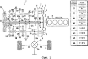
фиг.1 - общая схема силового агрегата гибридного транспортного средства согласно первому варианту выполнения настоящего изобретения;figure 1 is a General diagram of the power unit of a hybrid vehicle according to the first embodiment of the present invention;
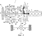
фиг.2 - общая схема силового агрегата гибридного транспортного средства согласно первому варианту выполнения настоящего изобретения, на которой показано соединение для приведения в действие двигателя;2 is a general diagram of a power unit of a hybrid vehicle according to a first embodiment of the present invention, which shows a connection for driving an engine;
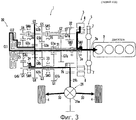
фиг.3 - общая схема силового агрегата гибридного транспортного средства согласно первому варианту выполнения настоящего изобретения, на которой показано соединение при инициировании обратного хода транспортного средства;figure 3 is a General diagram of the power unit of a hybrid vehicle according to the first embodiment of the present invention, which shows the connection when initiating the reverse of the vehicle;
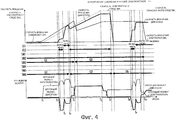
фиг.4 - пояснительная схема, на которой показана работа силового агрегата гибридного транспортного средства согласно первому варианту выполнения изобретения при инициировании движения/движении транспортного средства в режиме электромобиля;4 is an explanatory diagram showing the operation of the power unit of a hybrid vehicle according to the first embodiment of the invention when initiating movement / movement of the vehicle in an electric vehicle mode;
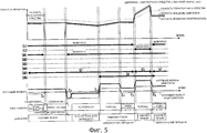
фиг.5 - пояснительная схема, на которой показана работа силового агрегата гибридного транспортного средства согласно первому варианту выполнения изобретения при движении транспортного средства с высокой скоростью;5 is an explanatory diagram showing the operation of the power unit of a hybrid vehicle according to the first embodiment of the invention when the vehicle is moving at high speed;
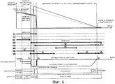
фиг.6 - пояснительная схема, на которой показана работа силового агрегата гибридного транспортного средства согласно первому варианту выполнения изобретения при движении транспортного средства с замедлением;6 is an explanatory diagram showing the operation of a power unit of a hybrid vehicle according to a first embodiment of the invention when the vehicle is traveling in a deceleration;
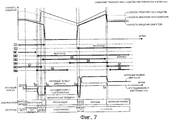
фиг.7 - пояснительная схема, на которой показана работа силового агрегата гибридного транспортного средства согласно первому варианту выполнения изобретения при повторном ускорении транспортного средства после движения с пониженной скоростью;7 is an explanatory diagram showing the operation of the power unit of a hybrid vehicle according to the first embodiment of the invention when the vehicle is re-accelerated after driving at a reduced speed;
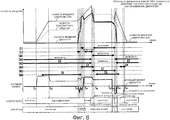
фиг.8 - пояснительная схема, на которой показана работа силового агрегата гибридного транспортного средства согласно первому варианту выполнения изобретения при переключении транспортного средства из режима электромобиля в режим двигателя внутреннего сгорания;Fig. 8 is an explanatory diagram showing the operation of a power unit of a hybrid vehicle according to a first embodiment of the invention when switching a vehicle from an electric vehicle to an internal combustion engine;
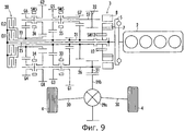
фиг.9 - общая схема силового агрегата гибридного транспортного средства согласно модифицированному варианту выполнения изобретения;Fig.9 is a General diagram of the power unit of a hybrid vehicle according to a modified embodiment of the invention;
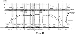
фиг.10 - график, показывающий работу силового агрегата, представленного на фиг.9;figure 10 is a graph showing the operation of the power unit shown in figure 9;
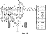
фиг.11 - общая схема силового агрегата гибридного транспортного средства согласно второму предпочтительному варианту выполнения настоящего изобретения.11 is a General diagram of the power unit of a hybrid vehicle according to a second preferred embodiment of the present invention.
Первый вариант выполнения изобретенияFirst Embodiment
На фиг.1 показан силовой агрегат гибридного транспортного средства согласно первому варианту выполнения изобретения. Силовой агрегат содержит трансмиссию 1, двигатель 2 и электромотор 3 в качестве мотора и предназначен для передачи мощности двигателя 2 или электромотора 3 посредством трансмиссии 1 на пару ведущих колес 4, 4 транспортного средства и обеспечивает приведение в движение колес 4, 4, составляющих приводной узел.Figure 1 shows the power unit of a hybrid vehicle according to a first embodiment of the invention. The power unit contains a
В настоящем варианте выполнения изобретения двигатель 2 является двигателем внутреннего сгорания, вырабатывающим энергию (крутящий момент) при воспламенении топлива, например бензина, дизельного топлива и спирта или т.п. Двигатель 2 имеет выходной вал (кривошипный вал) 2а для вывода произведенной мощности наружу. Указанный двигатель 2 аналогичен обычному двигателю транспортного средства, выходная мощность которого регулируется степенью открытия дроссельной заслонки, содержащей трубопровод для впуска воздуха, не показанный на чертеже (позволяющей регулировать количество впускаемого воздуха в двигатель 2), при этом выходная мощность передается посредством выходного вала 2а. На выходном валу 2а двигателя установлен маховик 5, а также предусмотрен ведущий вал 25 коробки передач, который вращается вместе с выходным валом 2а.In the present embodiment, the
В настоящем варианте выполнения изобретения электромотор 3 является трехфазным бесщеточным мотором постоянного тока и содержит ротор (вращающуюся часть) 7, поддерживаемый с возможностью вращения в корпусе 6, статор 8, закрепленный на корпусе 6 по периферии ротора 7, и выходной вал 3а для передачи наружу произведенной ротором 7 мощности (крутящего момента). Ротор 7 оснащен множеством постоянных магнитов, а статор 8 оснащен трехфазной катушкой 8а (обмоткой якоря). В данном случае корпус 6 электромотора 3 закреплен на стационарной части, которая является неподвижной относительно кузова транспортного средства, являющегося внешним корпусом моторного устройства или т.п.In the present embodiment, the
Выходной вал 3а электромотора, внутренняя часть которого коаксиальна ротору 7, вращается с ротором 7 как единое целое и конфигурирован с возможностью соединения с ведущим валом 25 коробки передач через первое соединительное устройство (SM1). Кроме того, выходной вал 3а электромотора конфигурирован с возможностью соединения с первым входным валом 21 или вторым входным валом 22 (который будет описан далее) через второе соединительное устройство (SM2).The
Первое соединительное устройство (SM1), состоящее из (первого) синхронизатора (синхронизатора коробки передач), размещенного в роторе 7 электромотора 3, имеет внутреннюю часть, коаксиальную выходному валу 2а двигателя 2 и выходному валу 3а электромотора 3. Аналогично второе соединительное устройство (SM2), состоящее из (второго) синхронизатора, размещенного вне электромотора 3, конфигурировано коаксиально выходному валу 2а двигателя 2 и выходному валу 3а электромотора 3.The first connecting device (SM1), consisting of a (first) synchronizer (transmission synchronizer) located in the
Катушка 8а электромотора 3 электрически соединена с аккумулятором (аккумуляторной батареей), являющимся источником постоянного тока, через блок электродвигательного привода (PDU), который является управляющей схемой, включающей инверторную схему (не показано). Кроме того, обеспечено электрическое соединение PDU с электронным блоком управления (ECU), который выполняет регулировку движения силового агрегата, включая электромотор 3. Электромотор конфигурирован так, что мощность (крутящий момент), производимая ротором 7 электромотора 3, регулируется электронным блоком управления за счет регулировки тока, поступающего к катушке 8а через PDU. В этом случае регулировка PDU позволяет электромотору 3 работать в режиме генерирования мощности, создающей крутящий момент для движения транспортного средства, при этом энергия к электромотору поступает от аккумуляторной батареи, а также позволяет электромотору работать в режиме рекуперации энергии, при котором создается рекуперативный крутящий момент (рекуперация энергии крутящего момента при торможении транспортного средства) на роторе 7 и посредством механической энергии (вращательной энергии), подаваемой извне через выходной вал 3а электромотора к ротору 7, вырабатывается электроэнергия, которая заряжает аккумуляторную батарею.The coil 8a of the
Вышеупомянутый электронный блок управления (ECU) является электрическим блоком, содержащим центральный процессор (CPU), оперативную память (RAM), постоянную память (ROM) и схему интерфейса или т.п. и выполняет регулировку работы силового агрегата в соответствии с заданной программой. В этом случае в дополнение к функции регулировки работы электромотора 3 через PDU введена функция регулировки работы двигателя 2 через исполнительный механизм, позволяющая регулировать двигатель посредством исполнительного механизма для дроссельной заслонки или ему подобного (не показано), а также введена функция регулировки работы блока 20 двойного сцепления, который будет описан далее, с помощью схемы управления или исполнительным механизмом (не показано), при этом указанные функции регулировки осуществляются электронным блоком управления (ECU).The above electronic control unit (ECU) is an electrical unit comprising a central processing unit (CPU), random access memory (RAM), read-only memory (ROM) and an interface circuit or the like. and adjusts the operation of the power unit in accordance with a given program. In this case, in addition to the function of adjusting the operation of the
Трансмиссия 1 содержит блок 20 двойного сцепления, полый первый входной вал 21, в который вставлен ведущий вал 25 коробки передач, полый второй входной вал 22, установленный на одной и той же оси с первым входным валом 21 и являющийся продолжением первого входного вала 21, блоки G1-G7 и GR шестерен, имеющие различные передаточные отношения (передаточное отношение ведомой шестерни и ведущей шестерни), размещенные последовательно со стороны двигателя 2. Здесь ссылочные позиции (G1-G7, GR) каждого блока шестерен обозначают ступени передаточных отношений шестерен (от первой передачи к седьмой передаче и передачу обратного хода), соответственно.
Ведущий вал 25 коробки передач имеет внутреннюю часть, коаксиальную выходному валу 2а, и соединен с выходным валом 2а двигателя 2 так, что они вращаются как единое целое. В этом случае соединение ведущего вала 25 коробки передач с ротором 7 и выходным валом 3а электромотора 3 может прерываться (соединяться/разъединяться) первым соединительным устройством (SM1).The
Блок 20 двойного сцепления содержит первое сцепление (CL1) и второе сцепление (CL2), которые коаксиальны ведущему валу 25 коробки передач и предназначены для передачи вращения ведущего вала 25 коробки передач к первому входному валу 21 через первое сцепление (CL1) и ко второму входному валу 22 через второе сцепление (CL2), соответственно.The dual
Вышеупомянутое первое и второе сцепления CL1 и CL2 являются включающими механизмами, функционирующими для соединения и разъединения ведущего вала 25 коробки передач с первым и со вторым входными валами 21, 22, и регулируются электронным блоком управления (ECU) (указанные сцепления способны избирательно работать в положении соединения и положении разъединения). Таким образом, первое и второе сцепления CL1 и CL2 состоят из фрикционного механизма сцепления, который может быть включен и выключен и передает вращение ведущего вала 25 коробки передач, согласованное с выходным валом 2а двигателя, к первому входному валу 21 и ко второму входному валу 22 соответственно.The aforementioned first and second clutches CL1 and CL2 are actuating mechanisms for connecting and disconnecting the
Каждый блок G1-G7 шестерен состоит из соответствующих ведущих шестерен G1a-G7a и ведомых шестерен G1b-G7b, каждая из которых сцепляется с соответствующей ведущей шестерней. В данном случае ведущие шестерни G1a, G3a (общие для G3 и G5) и G7a нечетных передач в блоке G1, G3, G5 и G7 шестерен установлены на первом входном валу 21, и ведущие шестерни G2a (общие для G2 и GR) и G4a (общие для G4 и G6) четных передач в блоке G2, G4, G6 и GR шестерен установлены на втором входном валу 22.Each gear unit G1-G7 consists of respective drive gears G1a-G7a and driven gears G1b-G7b, each of which engages with a corresponding drive gear. In this case, pinion gears G1a, G3a (common for G3 and G5) and odd gears G7a in gear block G1, G3, G5 and G7 are mounted on the
Кроме того, трансмиссия 1 имеет два выходных вала 26, 27 и ведомые шестерни G1b, G3b, G4b и GRb, которые сцепляются с ведущими шестернями G1a, G3a, G4a и G2a блоков G1, G3, G4 и GR шестерен, установленными с возможностью вращения на первом выходном валу 26, и ведомые шестерни G2b, G5b, G6b и G7b, которые сцепляются с ведущими шестернями G2a, G3a, G4a и G7a блока G2, G5, G6 и G7 шестерен, установленными с возможностью вращения на втором выходном валу 27.In addition, the
Кроме того, третий синхронизатор (синхронизатор коробки передач) SM3, который избирательно соединяет ведомую шестерню G1b первого блока G1 шестерен и ведомую шестерню G3b третьего блока G3 шестерен с первым выходным валом 26, и четвертый синхронизатор SM4, который избирательно соединяет ведомую шестерню G4b четвертого блока G4 шестерен и ведомую шестерню GRb блока GR шестерен передачи заднего хода с первым выходным валом 26, установлены на первом выходном валу 26. При этом пятый синхронизатор SM5, который избирательно соединяет ведомую шестерню G5b пятого блока G5 шестерен и ведомую шестерню G7b седьмого блока G7 шестерен со вторым выходным валом 27, и шестой синхронизатор SM6, который избирательно соединяет ведомую шестерню G2b второго блока G2 шестерен и ведомую шестерню G6b шестого блока G6 шестерен со вторым выходным валом 27, установлены на втором выходном валу 27.In addition, a third synchronizer (transmission synchronizer) SM3, which selectively connects the driven gear G1b of the first gear block G1 and the driven gear G3b of the third gear block G3, with the
Третий и четвертый синхронизаторы SM3, SM4 являются механизмами, тормозящими завихрения на первом выходном валу 26, и содержат синхронизирующие муфты 33, 34, выполненные с возможностью перемещения в осевом направлении под действием исполнительного механизма, который не показан. При перемещении синхронизирующей муфты 33 третьего синхронизатора SM3 из указанного нейтрального положения N к ведомой шестерне G1b или G3b, ведомая шестерня G1b или G3b соединяется с первым выходным валом 26, таким образом, избирательно формируя первый блок G1 шестерен или третий блок G3 шестерен. Аналогично при перемещении синхронизирующей муфты 34 четвертого синхронизатора SM4 из указанного нейтрального положения N к ведомой шестерне GRb или G4b ведомая шестерня GRb или G4b соединяется с первым выходным валом 26, таким образом, избирательно формируя блок GR шестерен передачи заднего хода или четвертый блок G4 шестерен.The third and fourth synchronizers SM3, SM4 are mechanisms that inhibit turbulence on the
Кроме того, пятый и шестой синхронизаторы SM5, SM6 являются механизмами, тормозящими завихрения на втором выходном валу 27, и содержат синхронизирующие муфты 35, 36, способные перемещаться в осевом направлении под действием исполнительного механизма, который не показан. При перемещении синхронизирующей муфты 35 пятого синхронизатора SM5 из указанного нейтрального положения N к ведомой шестерне G5b или G7b ведомая шестерня G5b или G7b соединяется со вторым выходным валом 27, таким образом, избирательно формируя пятый блок G5 шестерен или седьмой блок G7 шестерен. Аналогично при перемещении синхронизирующей муфты 36 шестого синхронизатора SM6 из указанного нейтрального положения N к ведомой шестерне G2b или G6b ведомая шестерня G2b или G6b соединяется со вторым выходным валом 27, таким образом, избирательно формируя второй блок G2 шестерен или шестой блок G6 шестерен.In addition, the fifth and sixth synchronizers SM5, SM6 are mechanisms that inhibit turbulence on the
В данном случае под словосочетанием «формируя блок шестерен» подразумевается обеспечение передачи мощности от входного вала 21, 22 на соответствующие выходные валы 26, 27 посредством блока G1-G7 или GR шестерен.In this case, the phrase "forming a block of gears" means ensuring the transfer of power from the
Вышеупомянутые первый и второй передаточные выходные валы 26, 27 установлены параллельно ведущему валу 25 коробки передач и соединены с ведущими колесами 4, 4 транспортного средства посредством блока 29 дифференциала, расположенного между ведущими колесами 4, 4. Конкретнее, блок 29 дифференциала содержит картер 29а, вмещающий полуосевую шестерню (не показано), соединенную с ведущими колесами 4, 4 через оси 30, 30 соответственно, и шестерню 29b, установленную на внешней периферии картера 29а. Таким образом, выходная шестерня 31 или 32, установленная на одном концевом участке первого передаточного выходного вала 26 или второго передаточного выходного вала 27, сцепляется с шестерней 29b блока 29 дифференциала. Согласно этому передаточные выходные валы 26, 27 сформированы таким образом, чтобы обеспечивать вращение ведущих колес 4, 4 транспортного средства через блок 29 дифференциала.The aforementioned first and second
Далее будет описан первый вариант выполнения настоящего изобретения. В указанном варианте выполнения изобретения используется электронный блок управления (ECU).Next, a first embodiment of the present invention will be described. In this embodiment, an electronic control unit (ECU) is used.
Приведение в действие двигателяEngine actuation
К примеру, если отсутствует возможность инициирования движения транспортного средства в режиме электромобиля (которая определяется электронным блоком управления) из-за низкой внешней температуры или уменьшенного напряжении (SOC) аккумуляторной батареи, имеется возможность привести в действие двигатель 2 электромотором 3.For example, if there is no possibility of initiating the movement of the vehicle in the electric vehicle mode (which is determined by the electronic control unit) due to the low external temperature or the reduced voltage (SOC) of the battery, it is possible to drive the
Конкретнее, первое соединительное устройство SM1 заблаговременно соединено (занимает первое рабочее положение), в то время как второе соединительное устройство SM2 разъединено (занимает второе рабочее положение). При этом, как показано жирной линией на фиг.2, выходной вал электромотора 3 находится в положении соединения с выходным валом 2а двигателя, который соединен с ведущим валом 25 коробки передач.More specifically, the first connecting device SM1 is connected in advance (occupies the first operating position), while the second connecting device SM2 is disconnected (occupying the second operating position). In this case, as shown by the thick line in figure 2, the output shaft of the
В этом положении, когда тормоз транспортного средства выключен, имеется возможность привести в действие двигатель 2 через выходной вал 2а посредством электромотора 3. В данном случае, когда первое сцепление CL1 или второе сцепление CL2 блока 20 двойного сцепления переходит в сцепленное состояние, мощность от ведущего вала 25 коробки передач передается на первый входной вал 21 или на второй входной вал 22 и, соответственно, через блоки шестерен мощность передается на первый выходной вал 26 или на второй выходной вал 27. При этом ведущие колеса 4, 4 транспортного средства приводятся в движение через выходные шестерни 31 или 32, и транспортное средство способно незамедлительно начать движение.In this position, when the vehicle brake is turned off, it is possible to drive the
Напротив, в приводном механизме с обычным двойным сцеплением, поскольку двигатель приводится в действие электромотором через двойное сцепление, перед приведением в действие двигателя необходимо задействовать управляющую мощность для включения сцепления. Согласно настоящему варианту выполнения изобретения двигатель 2 можно привести в действие непосредственно электромотором 3, что исключает необходимость в управляющей мощности для включения сцепления перед приведением в действие двигателя.In contrast, in a conventional dual-clutch drive mechanism, since the engine is driven by an electric motor through a dual clutch, control power must be used to engage the clutch before actuating the engine. According to the present embodiment, the
Инициирование движения транспортного средства задним ходомReverse vehicle initiation
Прежде всего, как и при описанном выше приведении в действие двигателя, первое соединительное устройство SM1 устанавливается в рабочее положение и двигатель 2 приводится в действие электромотором 3. Затем, когда четвертый синхронизатор SM4 перемещается к передаче (R) заднего хода, как уже описывалось, ведомая шестерня GRb блока GR шестерен передачи заднего хода соединяется с первым выходным валом 26, и формируется блок GR шестерен передачи заднего хода.First of all, as with the motor driving described above, the first connecting device SM1 is set to the operating position and the
Поэтому после приведения в действие двигателя 2, когда второе сцепление CL2 блока 20 двойного сцепления приходит в сцепленное состояние, как показано жирной линией на фиг.3, мощность передается на второй входной вал 22 от ведущего вала 25 коробки передач, который соединен с выходным валом 2а двигателя, и, соответственно, через блок GR шестерен передачи заднего хода мощность передается на первый выходной вал 26. При этом ведущие колеса 4, 4 приводятся в движение через выходную шестерню 31 и транспортное средство незамедлительно может начать движение обратным ходом, т.е. будет двигаться назад. В этом случае электромотор 3, соответственно, оказывает помощь двигателю или выполняет рекуперацию энергии.Therefore, after driving the
Инициирование движения транспортного средства в режиме электромобиля - движение транспортного средства, обеспечиваемое двигателем - движение транспортного средства с постоянной скоростью в режиме электромобиля.Initiation of vehicle movement in electric vehicle mode - vehicle movement provided by the engine - vehicle movement at a constant speed in electric vehicle mode.
В верхней части пояснительной схемы, приведенной на фиг.4, жирной линией показано изменение скорости вращения двигателя (отмеченное как «скорость вращения двигателя»), тонкой линией показано изменение скорости вращения электромотора (отмеченное как «скорость вращения электромотора») и пунктирной линией показано изменение скорости транспортного средства в зависимости от затраченного времени Т. В средней части схемы жирной линией показано сцепленное положение (ON) первого сцепления CL1, второго сцепления CL2, первого соединительного устройства (синхронизатора) SM1, второго соединительного устройства SM2, а также, соответственно, жирной линией показано положение от третьего до шестого синхронизаторов SM3-SM6, формирующих один из соответствующих двух блоков шестерен. На схеме точечной линией показано, что CL1, CL2, SM1, SM2 находятся в положении разъединения, или SM3-SM6 находятся в нейтральном положении N. В нижней части схемы жирной линией показано изменение крутящего момента двигателя (отмеченного как «крутящий момент двигателя») и тонкой линией показано изменение крутящего момента электромотора (отмеченного как «крутящий момент электромотора») в зависимости от затраченного времени Т.In the upper part of the explanatory diagram shown in Fig. 4, the bold line shows the change in engine speed (marked as "engine speed"), the thin line shows the change in engine speed (marked as "motor speed") and the dashed line shows the change vehicle speed depending on the time spent T. In the middle part of the circuit, the bold line shows the engaged position (ON) of the first clutch CL1, the second clutch CL2, the first connecting device In addition, the position (synchronizer) SM1, the second connecting device SM2, and also, respectively, the bold line shows the position from the third to the sixth synchronizers SM3-SM6, forming one of the corresponding two gear blocks. The dotted line diagram shows that CL1, CL2, SM1, SM2 are in the disconnected position, or SM3-SM6 are in the neutral position N. At the bottom of the diagram, the bold line shows the change in engine torque (marked as “engine torque”) and a thin line shows the change in the torque of the electric motor (marked as "torque of the electric motor") depending on the time spent T.
(1) Инициирование движения транспортного средства в режиме электромобиля(1) Initiation of vehicle movement in electric vehicle mode
Если транспортное средство остановлено и определено, что заряженность (SOC) аккумуляторной батареи равна заданной величине или превышает ее, а двигатель является теплым, выбирается вариант «инициирование движения транспортного средства в режиме электромобиля» и регулировка производится согласно фиг.4 и будет описана ниже.If the vehicle is stopped and it is determined that the charge (SOC) of the battery is equal to or greater than the set value and the engine is warm, the option “initiate vehicle movement in electric vehicle mode” is selected and the adjustment is made according to FIG. 4 and will be described below.
Предварительно SM2 устанавливается в положение ON, SM3 смещается к G1 (первая передача), SM6 смещается к G6 (шестая передача), соответственно. Когда в произвольный момент времени (Т=Т1) выжата педаль акселератора, электромотор приводится в действие (крутящий момент электромотора является приблизительно постоянным), при этом CL1 и CL2 поддерживаются отключенными (разъединенными) и вращение от выходного вала 3а электромотора передается на первый входной вал 21 через SM2. Затем, поскольку вращение передается на первый выходной вал 26 через блок G1 шестерен, сформированный посредством SM3, инициирование движения транспортного средства в режиме электромобиля происходит на первой передаче, и скорость транспортного средства увеличивается, как показано на графике пунктирной линией. В это время двигатель 2 остановлен (крутящий момент двигателя =0).Previously, SM2 is set to ON, SM3 is shifted to G1 (first gear), SM6 is shifted to G6 (sixth gear), respectively. When the accelerator pedal is depressed at an arbitrary point in time (T = T1), the electric motor is driven (the electric motor torque is approximately constant), while CL1 and CL2 are kept disconnected (disconnected) and rotation from the
(2) Крутящий момент электромотора возрастает, двигатель активируется на шестой передаче(2) The torque of the electric motor increases, the engine is activated in sixth gear
Когда в момент времени (Т=Т2) скорость транспортного средства или требуемая движущая сила равны заданной величине или превышают ее, двигатель 2 приводится в действие. Одновременно второе сцепление CL2 устанавливается в положение ON, вращение от ведущего вала 25 коробки передач передается на второй входной вал 22. Затем, поскольку вращение передается через блок G6 шестерен, сформированный посредством SM6, на второй выходной вал 27, двигатель активируется на шестой передаче. А именно для приведения двигателя в действие без потери движущей силы, которая инициируется электромотором 3, добавляется необходимый крутящий момент (= момент, приводящий в действие двигатель × передаточное число на шестой передаче/передаточное число на первой передаче/коэффициент передачи трансмиссии). Таким образом, что касается двигателя, то он активируется на шестой передаче электромотором 3, активируемым на первой передаче, и происходит увеличение крутящего момента электродвигателя, при этом для активации двигателя 2 требуется меньший крутящий момент.When at a point in time (T = T2) the vehicle speed or the required driving force is equal to or exceeds a predetermined value, the
(3) Двигатель приводится в действие при переключении на первую передачу и при увеличении скорости вращения двигателя(3) The engine is driven by shifting to first gear and increasing engine speed
Когда в момент времени (Т=Т3) двигатель 2 активирован, происходит переключение рабочих положений сцеплений блока 20 двойного сцепления. А именно CL2 не активировано (разъединено) и CL1 установлено в положение ON (соединено), в результате чего вращение от ведущего вала 25 коробки передач передается на первый входной вал 21, а не на второй входной вал 22. Затем через блок G1 шестерен, который сформирован посредством SM3, вращение передается на первый выходной вал 26, таким образом, двигатель активируется на первой передаче. При этом со стороны электромотора 3, как и в вышеописанном варианте (2), добавляется крутящий момент, необходимый для увеличения скорости вращения двигателя, при этом предотвращается потеря движущей силы. И затем, когда скорость вращения двигателя достигает заданной величины или превышает ее, двигатель запускается посредством впрыска топлива и воспламенения.When at time (T = T3) the
(4) Вторая передача двигателя(4) Second gear engine
Далее SM6 в момент времени Т=Т4 смещается к G2 и снова переключается в рабочее положение двух сцеплений. А именно CL1 не приводится в действие, а CL2 устанавливается в положение ON (соединено), посредством которого вращение от ведущего вала 25 коробки передач передается на второй входной вал 22. Затем вращение через блок G2 шестерен, который сформирован посредством SM6, передается на второй выходной вал 27, и движение транспортного средства на второй передаче обеспечивается двигателем.Next, SM6 at time T = T4 shifts to G2 and switches back to the working position of the two clutches. Namely, CL1 is not actuated, and CL2 is set to ON (connected), by which the rotation from the
(5) Переключение электромотора 3 на третью передачу при движении транспортного средства на второй передаче, обеспечиваемом двигателем.(5) Switching the
После переключения SM3 от G1 к G3 в момент времени Т=Т5 вращение от выходного вала 3а электромотора передается на первый входной вал 21 и затем через блок G3 шестерен передается на первый выходной вал 26, таким образом, электромотор 3 переключается на третью передачу. При этом наряду с уменьшением крутящего момента электромотора до 0, увеличивается крутящий момент двигателя, чтобы общее усилие, развиваемое двигателем, было равно требуемой величине.After switching SM3 from G1 to G3 at time T = T5, the rotation from the
(6) Увеличение крутящего момента электромотора в соответствии с требуемой движущей силой(6) Increasing the torque of the electric motor in accordance with the required driving force
Когда во время движения транспортного средства с помощью двигателя требуемая движущая сила достигает заданной величины или превышает ее, увеличивается крутящий момент электромотора. Кроме того, когда напряжение аккумуляторной батареи (SOC) становится равно заданной величине или меньше ее, зарядку производит электромотор 3, и в то же самое время добавляется крутящий момент двигателя, чтобы обеспечивалась необходимая общая движущая сила. Затем с момента времени (Т=Т6), когда скорость транспортного средства становится постоянной, крутящий момент двигателя начинает постепенно уменьшаться.When, during the movement of the vehicle by the engine, the required driving force reaches or exceeds a predetermined value, the torque of the electric motor increases. In addition, when the battery voltage (SOC) becomes equal to or less than a predetermined value, the
(7) Движение транспортного средства с постоянной скоростью(7) Vehicle at a constant speed
Во время движения транспортного средства, обеспечиваемого двигателем, если требуемая движущая сила равна заданной величине или меньше ее, скорость транспортного средства находится в пределах заданного диапазона и напряжение аккумуляторной батареи (SOC) равно заданной величине или превышает ее, то электронный блок управления (ECU) определяет, что возможно движение транспортного средства в режиме электромобиля с постоянной скоростью, и в момент времени (Т=Т7) CL2 переводится в отключенное положение (разъединяется). При этом режиме вращение от ведущего вала 25 коробки передач не передается ни на первый входной вал 21, ни на второй входной вал 22, вследствие чего останавливается двигатель (крутящий момент двигателя =0) или отключается подача топлива, либо останавливаются все цилиндры. Кроме того, SM6 перемещается от G2 к G6.During the movement of the vehicle provided by the engine, if the required driving force is equal to or less than the specified value, the vehicle speed is within the specified range and the battery voltage (SOC) is equal to or exceeds the specified value, the electronic control unit (ECU) determines that it is possible that the vehicle moves in an electric vehicle mode at a constant speed, and at time (T = T7) CL2 is switched off (disconnected). In this mode, rotation from the
В данном случае электронный блок управления на основании режима переключения или навигационной информации принимает решение об остановке двигателя или остановке цилиндров.In this case, the electronic control unit, based on the switching mode or navigation information, makes a decision to stop the engine or stop the cylinders.
(9) Приведение в действие двигателя на передаче от третьей до шестой при повторном ускорении транспортного средства(9) Drive the engine in gears from third to sixth when the vehicle is accelerated again
Во время вышеупомянутого движения транспортного средства в режиме электромобиля с постоянной скоростью транспортное средство в режиме электромобиля движется на третьей передаче, поскольку вращение от выходного вала 3а электромотора передается на первый входной вал 21 и через блок G3 шестерен передается на первый выходной вал 26. Во время указанного движения транспортного средства в режиме электромобиля при повторном ускорении активируется двигатель, поскольку SM2 устанавливается в положение ON, SM3 перемещается к G3 (третья передача) и SM6 перемещается к G6 (шестая передача) и когда CL2 устанавливается в положение ON (соединено) в момент времени (Т=Т8), как и в вышеупомянутом варианте (2), вращение от ведущего вала 25 коробки передач передается на второй входной вал 22 и через блок G6 шестерен передается на второй выходной вал 27, таким образом, двигатель активируется на шестой передаче.During the aforementioned movement of the vehicle in the electric vehicle at a constant speed, the vehicle in the electric vehicle mode moves in the third gear, since the rotation from the
И далее, в момент времени Т=Т9, когда CL2 находится в отключенном положении (разъединено) и CL1 устанавливается в положение ON (соединено), вращение от ведущего вала 25 коробки передач передается на первый входной вал 21 и через блок G3 шестерен передается на первый выходной вал 26, двигатель 2 приводится в действие на третьей передаче. В то же самое время на стороне электромотора 3, как и в вышеописанном варианте (2), при движении транспортного средства предотвращается потеря движущей силы при увеличении крутящего момента, необходимого, чтобы увеличить скорость вращения двигателя.And further, at time point T = T9, when CL2 is in the off position (disconnected) and CL1 is set to ON (connected), rotation from the
После этого, если электромотор 3 не используется, в момент времени Т=Т10 SM2 переключается на разъединение и электромотор останавливается (скорость вращения электромотора =0).After that, if the
Согласно способу регулировки в вышеописанных вариантах (1)-(9) может быть уменьшен крутящий момент, требуемый для приведения в действие двигателя. Например, если на первой передаче передаточное отношение =12, а на шестой передаче передаточное отношение =2, крутящий момент, необходимый для приведения в действие двигателя, составляет только 120 (Нм)×2/12=20 (Нм). Таким образом, движение транспортного средства посредством электромотора и приведение в действие двигателя можно осуществить одним и тем же электромотором, без использования отдельного стартера (двигателя зажигания) ISG, что позволяет исключить ISG и существенно уменьшить вес и снизить стоимость транспортного средства.According to the adjustment method in the above embodiments (1) to (9), the torque required to drive the engine can be reduced. For example, if in the first gear, the gear ratio = 12, and in the sixth gear, the gear ratio = 2, the torque required to drive the engine is only 120 (Nm) × 2/12 = 20 (Nm). Thus, the vehicle can be driven by an electric motor and the engine can be driven by the same electric motor, without using a separate ISG starter (ignition engine), which eliminates ISG and significantly reduces weight and reduces the cost of the vehicle.
Движение транспортного средства с высокой скоростьюHigh speed vehicle movement
На фиг.5 представлена пояснительная схема, иллюстрирующая способ регулировки во время движения транспортного средства с высокой скоростью и на которой, аналогично фиг.4, показано изменение скорости вращения двигателя, изменение скорости вращения электромотора и изменение скорости транспортного средства в зависимости от затраченного времени Т и показано соединение (ON)/разъединение CL1, CL2, SM1 и SM2, формирование блоков шестерен посредством SM3-SM6, а также показано изменение крутящего момента электромотора и изменение крутящего момента двигателя в зависимости от затраченного времени Т. Кроме того, в нижней части схемы показано состояние как электромотора 3, так и двигателя 2.Fig. 5 is an explanatory diagram illustrating a method of adjusting while a vehicle is traveling at high speed, and in which, similarly to Fig. 4, a change in engine speed, a change in rotational speed of an electric motor and a change in vehicle speed depending on the elapsed time T and shows the connection (ON) / disconnection of CL1, CL2, SM1 and SM2, the formation of gear units by means of SM3-SM6, and also shows the change in the torque of the electric motor and the change in the torque of the motor For, depending on the time spent T. In addition, the lower part of the circuit shows the status of both
Как показано на фиг.5, во время движения транспортного средства с высокой скоростью, если только электромотор 3 не остановлен, то он оказывает помощь двигателю, при этом происходит рекуперация электроэнергии, или форсированная зарядка аккумулятора при установке SM1 в положение ON и соединении электромотора 3 с двигателем 2.As shown in FIG. 5, while the vehicle is moving at high speed, unless the
Таким образом, преемственность крутящего момента увеличивается во время помощи двигателю и рекуперации электроэнергии электромотором, и предотвращается уменьшение преемственности из-за того, что крутящий момент электромотора становится равным 0, когда блоки шестерен формируются заранее (во время предварительного переключения).Thus, the continuity of the torque increases while the engine is helping and the electric motor recovers, and the continuity is prevented due to the fact that the electric motor torque becomes 0 when the gear blocks are formed in advance (during the preliminary shift).
Движение транспортного средства при замедленииVehicle deceleration
На фиг.6 представлена пояснительная схема, иллюстрирующая способ регулировки во время движения транспортного средства со снижением скорости и на которой, аналогично фиг.5, показано изменение скорости вращения двигателя, изменение скорости вращения электромотора и изменение скорости транспортного средства в зависимости от затраченного времени Т и показано соединение (ОN)/разъединение CL1, CL2, SM1 и SM2, формирование блоков шестерен посредством SM3-SM6, а также показано изменение крутящего момента электромотора и изменение крутящего момента двигателя в зависимости от затраченного времени Т. Кроме того, в нижней части схемы показано состояние как электромотора 3, так и двигателя 2.FIG. 6 is an explanatory diagram illustrating a method of adjusting while the vehicle is moving at a reduced speed, and which, like FIG. 5, shows a change in engine speed, a change in electric motor speed and a change in vehicle speed depending on the time T and shows the connection (ON) / disconnection of CL1, CL2, SM1 and SM2, the formation of gear units by means of SM3-SM6, and also shows the change in the torque of the electric motor and the change in the torque of the motor in Eqn depending on the elapsed time T. In addition, in the lower part of the circuit shows the state how the
Как показано на фиг.6, когда электромотор находится в режиме рекуперации в момент времени Т=Т21, при котором высокая скорость движения транспортного средства, как показано выше на фиг.5, уменьшается посредством остановки всех цилиндров двигателя, SM2 устанавливается в положение ON и SM3 перемещается к G3 в момент времени Т=Т22 и транспортное средство двигается на третьей передаче посредством электромотора. Затем в момент времени Т=Т23 происходит переключение как CL1, так и CL2 в положение разъединения и двигатель останавливается. Кроме того, с момента времени Т=Т22 до момента (Т=Т30), когда SM3 переместился к G1 (Т=Т30), посредством установки рабочего положения SM6 и SM4 для предварительного переключения блоков G6, G4, G2 шестерен четных передач в режим ожидания, минимизируется задержка отклика при повторном введении в действие двигателя.As shown in FIG. 6, when the electric motor is in the recovery mode at time point T = T21, at which the high vehicle speed, as shown above in FIG. 5, is reduced by stopping all engine cylinders, SM2 is set to ON and SM3 moves to G3 at time point T = T22 and the vehicle moves in third gear by an electric motor. Then, at time T = T23, both CL1 and CL2 switch to the disconnect position and the engine stops. In addition, from the time T = T22 to the moment (T = T30), when SM3 moved to G1 (T = T30), by setting the working position SM6 and SM4 to pre-switch the even gear units G6, G4, G2 to standby , minimizes the delay in response to the re-commissioning of the engine.
Переход при движении транспортного средства от снижения скорости к повторному ускорениюTransition during vehicle movement from a decrease in speed to a repeated acceleration
На фиг.7 представлена пояснительная схема, иллюстрирующая способ регулировки в случае повторного ускорения движения транспортного средства после снижения скорости и на которой, аналогично фиг.5 и 6, показано изменение скорости вращения двигателя, изменение скорости вращения электромотора и изменение скорости транспортного средства в зависимости от затраченного времени и показано соединение/разъединение CL1, CL2, SM1 и SM2, формирование блоков шестерен посредством SM3-SM6, а также показано изменение крутящего момента электромотора и изменение крутящего момента двигателя в зависимости от затраченного времени Т. Кроме того, в нижней части схемы показано состояние как электромотора 3, так и двигателя 2.Fig. 7 is an explanatory diagram illustrating a method of adjustment in the case of repeated acceleration of a vehicle after a decrease in speed, and which, like Figs. 5 and 6, shows a change in engine speed, a change in rotational speed of an electric motor, and a change in vehicle speed depending on elapsed time and shows the connection / disconnection of CL1, CL2, SM1 and SM2, the formation of gear blocks by means of SM3-SM6, and also shows the change in the torque of the electric motor and the change in utyaschego motor torque as a function of elapsed time T. In addition, in the lower part of the circuit shows the state how the
На фиг.7, как и ранее на фиг.6, показано, что во время рекуперации энергии при снижении скорости как CL1, так и CL2 находятся в положении разъединения и в момент времени (Т=Т23) двигатель остановлен, SM2 устанавливается в положение ON и SM3 перемещается к G3, и транспортное средство движется на третьей передаче посредством электромотора. В данном случае, когда CL2 устанавливается в положение ON в момент времени (Т=Т24), вращение от ведущего вала 25 коробки передач передается на второй входной вал 22. Затем через блок G4 шестерен, сформированный SM4, вращение передается на второй выходной вал 27, и двигатель снова приводится в действие на четвертой передаче. Таким образом, при увеличении крутящего момента электромотора увеличивается скорость вращения двигателя и имеется возможность быстро привести в действие двигатель.In Fig. 7, as previously in Fig. 6, it is shown that during energy recovery, with a decrease in speed, both CL1 and CL2 are in the disconnected position and at the time (T = T23) the engine is stopped, SM2 is set to ON and SM3 moves to G3, and the vehicle moves in third gear by an electric motor. In this case, when CL2 is set to ON at the time (T = T24), rotation from the
После того как SM3 в момент времени Т=Т25 переключился от G3 в нейтральное положение N, вращение от выходного вала 3а коробки передач не передается на первый выходной вал 26 и крутящий момент электромотора 3 становится равным 0, таким образом, движение транспортного средства на постоянной скорости обеспечивается двигателем.After SM3 at time moment T = T25 switched from G3 to the neutral position N, the rotation from the
Перед вышеописанным повторным ускорением, устанавливая рабочее положение SM4 и SM6 для предварительного переключения блоков G6 и G4 шестерен четных передач в режим ожидания, можно минимизировать задержку отклика при повторном приведении в действие двигателя.Before the re-acceleration described above, by setting the operating position of SM4 and SM6 for pre-switching the even gear units G6 and G4 to the standby mode, it is possible to minimize the response delay when the motor is re-activated.
Переключение режима электромобиля в режим движения транспортного средства, обеспечиваемого двигателемSwitching the electric vehicle mode to the vehicle driving mode provided by the engine
На фиг.8 представлена пояснительная схема, иллюстрирующая способ регулировки при переключении режима электромобиля в режим движения транспортного средства, обеспечиваемого двигателем, на которой, аналогично фиг.5-7, показано изменение скорости вращения двигателя, изменение скорости вращения электромотора и изменение скорости транспортного средства в зависимости от затраченного времени Т и показано соединение/разъединение CL1, CL2, SM, и SM2, формирование блоков шестерен посредством SM3-SM6, а также показано изменение крутящего момента электромотора и изменение крутящего момента двигателя в зависимости от затраченного времени Т. Кроме того, в нижней части схемы показано состояние как электромотора 3, так и двигателя 2.Fig. 8 is an explanatory diagram illustrating an adjustment method when switching the electric vehicle mode to the vehicle driving mode provided by the engine, which, similarly to Figs. 5-7, shows a change in engine speed, a change in the rotation speed of the electric motor and a change in vehicle speed in depending on the elapsed time T and shows the connection / disconnection of CL1, CL2, SM, and SM2, the formation of gear units by means of SM3-SM6, and also shows the change in torque by electric otore and change in engine torque depending on the time spent T. In addition, the status of both
Как показано на фиг.8, при выборе движения транспортного средства в режиме электромобиля, до момента (Т=Т31) времени инициирования движения в режиме электромобиля двигатель находится в режиме остановки, при этом как CL1, так и CL2 находятся в положении разъединения, транспортное средство находится в режиме ожидания, двигаясь на третьей передаче, при этом SM2 находится в положении ON и SM3 предварительно перемещается к G3. Затем, когда запущен режим электромобиля, как предварительно описано, во время движения транспортного средства в режиме электромобиля блоки G3 и G6 шестерен устанавливаются на постоянную передачу с момента времени Т=Т32. После этого CL2 устанавливается в положение ON в момент времени Т=Т3З, двигатель активируется на шестой передаче посредством G6, и затем CL1 устанавливается в положение ON и двигатель приводится в действие на третьей передаче посредством G3, далее CL2 снова устанавливается в положение ON в момент времени Т=Т34 и движение транспортного средства после ускорения на четвертой передаче (посредством включения G4) обеспечивается двигателем.As shown in Fig. 8, when selecting vehicle movement in the electric vehicle mode, until the time (T = T31) of the initiation time of the movement in electric vehicle mode, the engine is in the stop mode, while both CL1 and CL2 are in the disconnected position, the vehicle is in standby mode, moving in third gear, while SM2 is in the ON position and SM3 is previously moved to G3. Then, when the electric vehicle mode is started, as previously described, while the vehicle is traveling in the electric vehicle mode, the gear units G3 and G6 are set to be continuously transmitted from time T = T32. After that, CL2 is set to ON at time T = T3Z, the engine is activated in sixth gear by G6, and then CL1 is set to ON and the engine is activated in third gear by G3, then CL2 is again set to ON at time T = T34 and the movement of the vehicle after acceleration in fourth gear (by turning on G4) is provided by the engine.
Когда скорость движения транспортного средства, обеспечиваемого двигателем, в момент времени (Т=Т35) достигает заданной скорости, то за счет разъединения SM2, соединения SM1 и установки SM3 в нейтральное положение N, а также за счет перемещения SM5 к G7 вращение от выходного вала 3а электродвигателя будет передаваться на ведущий вал 25 коробки передач через выходной вал 2а двигателя. В данном случае, когда CL2 переключается в положение разъединения и CL1 установлено в положение ON, выходная мощность электромотора передается от ведущего вала 25 коробки передач на первый входной вал 21, и после переключения передачи на максимальную седьмую передачу G7 крутящий момент электромотора становится равным 0 (Т=Т36).When the speed of the vehicle provided by the engine at a point in time (T = T35) reaches a predetermined speed, then by disconnecting SM2, connecting SM1 and setting SM3 to neutral N, as well as by moving SM5 to G7, rotation from
После того как в момент времени Т=Т37 все цилиндры двигателя 2 остановлены, электромотор 3 переходит в режим рекуперации, и после уменьшения скорости вращения электромотора в момент времени Т=Т38 происходит разъединение SM1 и соединение SM2, а также перемещение SM3 к G3, в результате чего выход электромотора переключается на третью передачу через G3 от первого входного вала 21. При этом когда в момент времени (Т=Т38) крутящий момент электромотора реверсируется посредством торможения двигателем, электромотор 3 снова переходит в режим рекуперации и двигатель 2 останавливается в момент времени Т=Т39, электромотор 3 также останавливается в момент времени Т=Т40 и крутящий момент электромотора становится равным 0.After all the cylinders of
Модифицированный вариант выполнения изобретенияModified Embodiment
Согласно вышеупомянутому первому варианту выполнения изобретения предусмотрено два отдельных синхронизатора SM1 и SM2 в качестве соединительных устройств для соединения выходного вала 3а электромотора с ведущим валом 25 коробки передач и первым входным валом 21 (или вторым входным валом 22), чтобы обеспечивалась передача мощности, однако SM1 и SM2 могут быть совмещены с образованием единого синхронизатора. Указанный модифицированный вариант представлен на фиг.9.According to the aforementioned first embodiment of the invention, two separate synchronizers SM1 and SM2 are provided as connecting devices for connecting the
Согласно модифицированному варианту выполнения изобретения, представленному на фиг.9, имеется синхронизатор SM12, который сформирован концентрически ведущему валу 25 коробки передач и расположен по направлению от внутренней стороны ротора 7 электромотора 3 к блоку 20 двойного сцепления. SM12 является механизмом, тормозящим завихрения на ведущем валу 25 коробки передач, и содержит синхронизирующую муфту 12, выполненную с возможностью перемещения в осевом направлении под действием исполнительного механизма, который не показан.According to a modified embodiment of the invention shown in Fig. 9, there is a synchronizer SM12, which is formed concentrically to the
В данном случае синхронизирующая муфта 12 сформирована с возможностью избирательно устанавливаться в одно из положений, а именно, в первое рабочее положение, которое позволяет передавать мощность от выходного вала 3а электромотора на ведущий вал 25 коробки передач, и во второе рабочее положение, которое позволяет передавать мощность от выходного вала 3а электромотора на первый входной вал 21 или второй входной вал 22, а также может устанавливаться в нейтральное положение, которое отличается от вышеупомянутых двух рабочих положений и при котором не выполняется ни одна из вышеупомянутых двух передач мощности.In this case, the synchronizing
Согласно модифицированному варианту выполнения изобретения, представленному на фиг.9, имеется трансмиссия 1, в которой используется блок 20 двойного сцепления, а также имеется двигатель 2 и электромотор 3, и выполняется нижеследующая операция регулировки.According to a modified embodiment of the invention shown in FIG. 9, there is a
На фиг.10 в верхней части графика показано изменение скорости транспортного средства и состояние транспортного средства в зависимости от затраченного времени Т, а также жирной линией показано изменение скорости вращения двигателя и тонкой линией показано изменение скорости вращения электромотора в зависимости от затраченного времени Т. В нижней части графика показано изменение передач как двигателя, так и электромотора.Figure 10 in the upper part of the graph shows the change in vehicle speed and vehicle condition depending on the elapsed time T, and the bold line shows the change in engine speed and a thin line shows the change in rotational speed of the electric motor depending on elapsed time T. part of the graph shows the change in gears of both the engine and the electric motor.
Как показано на фиг.10, первоначально как двигатель, так и электромотор остановлены, и предварительно выполнено переключение электромотора на первую передачу. Регулировка описана ниже.As shown in FIG. 10, initially both the engine and the electric motor are stopped, and the electric motor is first shifted to first gear. The adjustment is described below.
(1) Начало движения транспортного средства посредством электромотора на первой передаче.(1) The beginning of the movement of the vehicle by means of an electric motor in first gear.
(2) Устанавливаются четные передачи G2, G4 или G6, при этом скорость вращения двигателя увеличивается, и он приводится в действие.(2) Even gears G2, G4 or G6 are installed, while the engine speed is increased and it is driven.
(3) Движение транспортного средства на второй передаче обеспечивается двигателем, и электромотор переключается на третью передачу.(3) The movement of the vehicle in second gear is provided by the engine, and the electric motor shifts to third gear.
(4) Движение транспортного средства в режиме электромобиля с постоянной скоростью на третьей передаче и остановка двигателя.(4) The movement of the vehicle in electric vehicle mode at a constant speed in third gear and engine shutdown.
(5) Устанавливаются нечетные передачи G1, G3, G5 или G7, двигатель приводится в действие, и движение транспортного средства с постоянной скоростью обеспечивается двигателем, при этом электромотор остановлен.(5) The odd gears G1, G3, G5 or G7 are installed, the engine is driven, and the vehicle is driven at a constant speed by the engine, while the electric motor is stopped.
(6) При переходе от средней скорости движения транспортного средства к высокой скорости задействованы двигатель и электромотор (помощь двигателю при движении и рекуперация обеспечивается электромотором). При движении с постоянной скоростью транспортного средства, обеспечиваемом двигателем, электромотор остановлен, а при рекуперации остановлены все цилиндры двигателя.(6) When moving from an average vehicle speed to a high speed, an engine and an electric motor are involved (assisting the engine with movement and recovery is provided by an electric motor). When driving at a constant vehicle speed provided by the engine, the electric motor is stopped, and during recovery all engine cylinders are stopped.
(7) Когда происходит рекуперация энергии при снижении скорости, двигатель приводится в действие на шестой передаче, и при рекуперации энергии все цилиндры остановлены. Электромотор включается на пятой передаче. Целью этого является минимизация крутящего момента торможения, производимого двигателем, и улучшение приемистости двигателя при повторном приведении в действие.(7) When energy recovery occurs when the speed decreases, the engine is driven in sixth gear, and all the cylinders are stopped during energy recovery. The electric motor engages in fifth gear. The purpose of this is to minimize the braking torque produced by the engine and to improve engine throttle response upon repeated actuation.
(8) При снижении скорости изменение скорости происходит за счет переключения передач при одновременном подключении всех отключенных цилиндров и при создании крутящего момента посредством торможения двигателем.(8) When the speed decreases, the speed changes due to gear shifting when all disconnected cylinders are connected at the same time and when torque is generated by engine braking.
(9) Во время рекуперации при снижении скорости от средней скорости до низкой скорости двигатель остановлен, и электромотор работает на первой передаче.(9) During recovery, when the speed decreases from medium speed to low speed, the engine is stopped and the electric motor runs in first gear.
(10) Чтобы быстро инициировать движение транспортного средства, выбираются нечетные передачи G1, G3, G5 или G7, скорость вращения двигателя увеличивается и двигатель приводится в действие.(10) To quickly initiate the movement of the vehicle, the odd gears G1, G3, G5 or G7 are selected, the engine speed is increased and the engine is driven.
Второй предпочтительный вариант выполнения изобретенияSecond preferred embodiment of the invention
На фиг.11 схематично показана конструкция гибридного транспортного средства, содержащего силовую установку согласно второму предпочтительному варианту выполнения изобретения. Поскольку данный вариант выполнения изобретения отличается от первого варианта выполнения изобретения только перечисленными ниже признаками, одинаковые ссылочные позиции обозначают одинаковые элементы в обоих вариантах выполнения изобретения, в связи с этим объяснение будет сокращено.11 schematically shows the design of a hybrid vehicle containing a power plant according to a second preferred embodiment of the invention. Since this embodiment of the invention differs from the first embodiment of the invention only by the features listed below, the same reference numbers denote the same elements in both embodiments of the invention, in this regard, the explanation will be shortened.
Согласно данному варианту выполнения изобретения используется двойной основной вал, и ниже представлены отличия от первого варианта выполнения изобретения.According to this embodiment of the invention, a double main shaft is used, and the differences from the first embodiment of the invention are presented below.
Согласно данному варианту выполнения изобретения трансмиссия содержит блок 20 двойного сцепления, полый первый входной вал 41, являющийся продолжением ведущего вала 25 коробки передач, который вращается вместе с выходным валом 2а двигателя 2, второй входной вал 42, размещенный параллельно первому входному валу 41, блоки G1 - G7 и GR шестерен с различными последовательными передаточными отношениями со стороны двигателя 2 и один выходной вал 44. Выходной вал 44 имеет один концевой участок с закрепленной на нем выходной шестерней 31, и он конфигурирован так, чтобы посредством сцепления выходной шестерни 31 с шестерней 29b блока 29 дифференциала обеспечивалось вращение ведущих колес 4, 4 транспортного средства через блок 29 дифференциала.According to this embodiment of the invention, the transmission comprises a double
В то время как первый входной вал 41, который является одним из основных валов, соединен с ведущим валом 25 коробки передач через первое сцепление CL1 блока 20 двойного сцепления, второй входной вал 42, который является другим основным валом, также соединен с ведущим валом 25 коробки передач через второе сцепление CL2, которое согласуется посредством промежуточной шестерни 43 с первым сцеплением CL1 блока 20 двойного сцепления.While the
Среди вышеупомянутых блоков шестерен ведущие шестерни G1a, G5a, G3a и G7a блоков G1, G5, G3 и G7 шестерен нечетных передач соединяются с первым входным валом 41 через SM7 и SM9 соответственно, и ведущие шестерни G2a, G4a, G6a и GRa блоков R, G2, G4, G6 и GR шестерен четных передач соединяются со вторым входным валом 42 через SM8 и SM10 соответственно. Кроме того, ведомые шестерни G1b, G4b, G3b и G6b, которые являются общими для каждой пары блоков G1 и G2, G4 и G5, G3 и GR, G6 и G7 шестерен, установлены с возможностью вращения на выходном валу 31 трансмиссии.Among the aforementioned gear units, the drive gears G1a, G5a, G3a and G7a of the odd gear units G1, G5, G3 and G7 are connected to the
Среди вышеупомянутых SM7-SM10 (от седьмого до десятого синхронизаторов) синхронизаторы SM7 и SM9 способны тормозить завихрения на первом входным валу 41 и содержат синхронизирующие муфты 37, 39, способные перемещаться в осевом направлении под действием исполнительного механизма, который не показан. При перемещении соответствующих синхронизирующих муфт 37, 39 из указанного нейтрального положения N к ведущей шестерне G1a или G5a либо к ведущей шестерне G3a или G7a происходит соединение с первым входным валом 41 ведущей шестерни G1a или G5a либо ведущей шестерни G3a или G7a, таким образом, избирательно формируются блоки G1 или G5, G3 или G7 шестерен.Among the aforementioned SM7-SM10 (from the seventh to tenth synchronizers), the SM7 and SM9 synchronizers are capable of inhibiting turbulence on the
Кроме того, синхронизаторы SM8 и SM10 способны тормозить завихрения на втором входном валу 42 и содержат синхронизирующие муфты 38, 40, способные перемещаться в осевом направлении под действием исполнительного механизма, который не показан. При перемещении соответствующих синхронизирующих муфт 38, 40 из указанного нейтрального положения N к ведущей шестерне G2a или G4a либо к ведущей шестерне G6a или GRa происходит соединение со вторым входным валом 42 ведущей шестерни G2a или G4a либо ведущей шестерни G6a или GRa, таким образом, избирательно формируются блоки G2 или G4; G6 или GR шестерен.In addition, synchronizers SM8 and SM10 are able to inhibit turbulence on the
Согласно второму предпочтительному варианту выполнения изобретения гибридное транспортное средство, содержащее двойной основной вал, работает аналогично гибридному транспортному средству согласно первому варианту выполнения изобретения, и достигается аналогичный эффект.According to a second preferred embodiment of the invention, the hybrid vehicle comprising the dual main shaft operates similarly to the hybrid vehicle according to the first embodiment of the invention, and a similar effect is achieved.
В вышеупомянутых вариантах выполнения изобретения синхронизатор SM используется в качестве соединительного устройства для соединения выходного вала электромотора с выходным валом двигателя или с входным валом. Однако это не является ограничительным, и могут использоваться соответствующие соединительные средства типа сцепления, переключаемого посредством исполнительного механизма по команде на переключение.In the aforementioned embodiments of the invention, the synchronizer SM is used as a connecting device for connecting the output shaft of the electric motor to the output shaft of the motor or to the input shaft. However, this is not limiting, and appropriate connecting means such as a clutch switched by means of an actuator on a switching command can be used.
Кроме того, блок двойного сцепления не ограничивается конструкцией, используемой в первом варианте выполнения изобретения и во втором варианте выполнения изобретения, и может иметь любую конструкцию, которая способна передавать мощность посредством двух сцеплений.In addition, the dual clutch unit is not limited to the structure used in the first embodiment of the invention and in the second embodiment of the invention, and may have any structure that is capable of transmitting power through two clutches.
Как описано выше, благодаря размещению электромотора в нижней части сцепления трансмиссии с двойным сцеплением и при наличии трансмиссии, исключающей какие-либо дополнительные средства для обеспечения работы двойного сцепления из состояния остановки, не увеличивается общая длина и общая ширина гибридного транспортного средства согласно изобретению, что способствует уменьшению веса и снижению стоимости транспортного средства.As described above, by placing the electric motor in the lower part of the clutch of the dual clutch transmission and in the presence of a transmission that excludes any additional means for ensuring the double clutch operation from the stopped state, the total length and overall width of the hybrid vehicle according to the invention does not increase, which contributes to weight reduction and vehicle cost reduction.
Claims (9)
Applications Claiming Priority (3)
| Application Number | Priority Date | Filing Date | Title |
|---|---|---|---|
| JP2009015790A JP4607222B2 (en) | 2009-01-27 | 2009-01-27 | Hybrid vehicle |
| JP2009-015790 | 2009-01-27 | ||
| PCT/JP2010/050913 WO2010087311A1 (en) | 2009-01-27 | 2010-01-25 | Hybrid vehicle |
Publications (1)
| Publication Number | Publication Date |
|---|---|
| RU2478043C1 true RU2478043C1 (en) | 2013-03-27 |
Family
ID=42395572
Family Applications (1)
| Application Number | Title | Priority Date | Filing Date |
|---|---|---|---|
| RU2011135814/11A RU2478043C1 (en) | 2009-01-27 | 2010-01-25 | Hybrid transport facility |
Country Status (7)
| Country | Link |
|---|---|
| US (1) | US8506450B2 (en) |
| EP (1) | EP2383139B1 (en) |
| JP (1) | JP4607222B2 (en) |
| CN (1) | CN102292231B (en) |
| BR (1) | BRPI1007405A2 (en) |
| RU (1) | RU2478043C1 (en) |
| WO (1) | WO2010087311A1 (en) |
Families Citing this family (50)
| Publication number | Priority date | Publication date | Assignee | Title |
|---|---|---|---|---|
| ATE548587T1 (en) * | 2009-11-13 | 2012-03-15 | Fiat Ricerche | DUAL CLUTCH TRANSMISSION OF A MOTOR VEHICLE HAVING A GEARSHIFT DEVICE COMPRISING A ROTARY DRUM AND HYBRID DRIVE SYSTEM OF A MOTOR VEHICLE INCLUDING SUCH A TRANSMISSION |
| CN102259583B (en) * | 2010-05-31 | 2014-03-19 | 比亚迪股份有限公司 | Hybrid power-driven system and vehicle provided with same |
| US8412396B2 (en) * | 2010-06-07 | 2013-04-02 | GM Global Technology Operations LLC | Electric launch of a hybrid vehicle having a belt alternator starter and a dual clutch transmission |
| CN102905929B (en) * | 2010-07-12 | 2015-06-17 | 本田技研工业株式会社 | Control device and control method for hybrid vehicle |
| JP2012032690A (en) | 2010-08-02 | 2012-02-16 | Seiko Epson Corp | Optical article and manufacturing method thereof |
| JP5770483B2 (en) * | 2011-02-09 | 2015-08-26 | 本田技研工業株式会社 | Vehicle drive device |
| JP2012247019A (en) * | 2011-05-30 | 2012-12-13 | Aisin Seiki Co Ltd | Vehicle drive system |
| ITTO20110483A1 (en) * | 2011-06-03 | 2012-12-04 | Oerlikon Graziano Spa | ELECTRIC PROPULSION SYSTEM FOR VEHICLES |
| AT511631B1 (en) | 2011-06-30 | 2013-04-15 | Avl List Gmbh | DOUBLE CLUTCH GEAR WITH SEVERAL SWITCHING GEARS |
| AT511632B1 (en) * | 2011-06-30 | 2013-04-15 | Avl List Gmbh | DRIVE TRAIN FOR ONE VEHICLE |
| JP5634967B2 (en) * | 2011-09-26 | 2014-12-03 | 本田技研工業株式会社 | Hybrid vehicle and control method thereof |
| FR2981611B1 (en) * | 2011-10-25 | 2014-02-28 | Renault Sa | THREE-SHAFT HYBRID TRANSMISSION FOR MOTOR VEHICLE AND CONTROL METHOD |
| DE102012102342A1 (en) * | 2012-03-20 | 2013-09-26 | Dr. Ing. H.C. F. Porsche Aktiengesellschaft | Procedure for starting the engine |
| EP2868543B1 (en) * | 2012-06-27 | 2020-07-22 | Toyota Jidosha Kabushiki Kaisha | Hybrid vehicle drive apparatus |
| JP2014058286A (en) * | 2012-09-19 | 2014-04-03 | Toyota Motor Corp | Control unit of hybrid vehicle |
| KR20140059917A (en) * | 2012-11-08 | 2014-05-19 | 현대자동차주식회사 | Double clutch powertrain for vehicle |
| US9539892B2 (en) * | 2013-05-30 | 2017-01-10 | GM Global Technology Operations LLC | Automated manual transmission with electric motor-generator |
| CN104417346B (en) | 2013-09-09 | 2017-04-12 | 比亚迪股份有限公司 | Control system and control method of hybrid electrical vehicle (HEV) |
| CN104417345B (en) * | 2013-09-09 | 2017-08-04 | 比亚迪股份有限公司 | Control system and control method for hybrid electric vehicle |
| CN104417554B (en) | 2013-09-09 | 2018-03-13 | 比亚迪股份有限公司 | Hybrid vehicle and its cruise control method |
| CN104417543B (en) | 2013-09-09 | 2017-08-22 | 比亚迪股份有限公司 | The control system and control method of hybrid vehicle |
| CN104417347B (en) | 2013-09-09 | 2017-08-04 | 比亚迪股份有限公司 | The control system and control method of hybrid vehicle |
| CN104417557B (en) | 2013-09-09 | 2017-07-04 | 比亚迪股份有限公司 | A kind of vehicle slides feedback control system and its control method |
| CN104417544B (en) | 2013-09-09 | 2017-08-22 | 比亚迪股份有限公司 | The control system and control method of hybrid vehicle |
| CN104417344B (en) | 2013-09-09 | 2017-03-15 | 比亚迪股份有限公司 | Hybrid vehicle and its drive control method |
| KR20150045299A (en) * | 2013-10-18 | 2015-04-28 | 현대자동차주식회사 | Hybrid power train for vehicle |
| JP6026990B2 (en) * | 2013-12-02 | 2016-11-16 | 本田技研工業株式会社 | Vehicle drive device |
| EP2883732B1 (en) | 2013-12-11 | 2017-11-15 | Volvo Car Corporation | A dual-clutch seven speed transmission arrangement for a hybrid vehicle and method therefore |
| JP6083612B2 (en) * | 2014-05-30 | 2017-02-22 | 本田技研工業株式会社 | Shift control device for automatic transmission |
| JP6251805B2 (en) * | 2014-06-11 | 2017-12-20 | Gknドライブラインジャパン株式会社 | Power transmission device |
| KR101611076B1 (en) * | 2014-09-23 | 2016-04-11 | 현대자동차주식회사 | Hybrid transmission for vehicle |
| KR101637686B1 (en) * | 2014-09-29 | 2016-07-08 | 현대자동차주식회사 | Hybrid transmission for vehicle |
| KR101637685B1 (en) * | 2014-09-29 | 2016-07-08 | 현대자동차주식회사 | Amt hybrid transmission |
| DE102014224512B4 (en) | 2014-12-01 | 2025-07-03 | Bayerische Motoren Werke Aktiengesellschaft | Drive train for a vehicle, in particular a motor vehicle |
| KR101664607B1 (en) * | 2014-12-02 | 2016-10-12 | 현대자동차주식회사 | Automated manual transmission |
| JP6287885B2 (en) * | 2015-02-18 | 2018-03-07 | トヨタ自動車株式会社 | Hybrid vehicle |
| US10677322B2 (en) * | 2015-02-19 | 2020-06-09 | Audi Ag | Dual clutch transmission for a motor vehicle |
| JP2017008959A (en) * | 2015-06-17 | 2017-01-12 | 本田技研工業株式会社 | Transmission gearbox |
| KR101822237B1 (en) | 2015-11-02 | 2018-01-26 | 현대자동차주식회사 | Automated manual transmission |
| CN206086345U (en) * | 2016-06-29 | 2017-04-12 | 比亚迪股份有限公司 | Power drive system and vehicle |
| DE102016217575A1 (en) | 2016-09-15 | 2018-03-15 | Volkswagen Aktiengesellschaft | Drive arrangement for a vehicle |
| CN108016282B (en) * | 2016-10-31 | 2019-11-05 | 比亚迪股份有限公司 | Power drive system and vehicle with it |
| FR3064575B1 (en) * | 2017-03-31 | 2019-11-08 | Peugeot Citroen Automobiles Sa | DEVICE FOR MONITORING THE COUPLINGS / DECOUPLAGES OF A NON-THERMAL MOTOR MACHINE OF A VEHICLE BASED ON A PARAMETER OF STATE OF ASSOCIATED STORAGE MEANS |
| KR102417907B1 (en) * | 2017-12-15 | 2022-07-07 | 현대자동차주식회사 | Vehicle and method for controlling speed thereof |
| US10569635B2 (en) | 2018-01-25 | 2020-02-25 | Zhihui Duan | Hybrid electric drive train of a motor vehicle |
| KR102554882B1 (en) * | 2018-04-12 | 2023-07-12 | 현대자동차주식회사 | Transmission for electric vehicle |
| KR102575183B1 (en) * | 2018-08-07 | 2023-09-05 | 현대자동차 주식회사 | Power transmission apparatus for vehicle |
| KR20210012542A (en) * | 2019-07-25 | 2021-02-03 | 현대자동차주식회사 | Power transmission system of hybrid electric vehicle |
| DE102020214533A1 (en) | 2020-11-18 | 2022-05-19 | Zf Friedrichshafen Ag | Hybrid transmission with electric traction support |
| IT202100018815A1 (en) * | 2021-07-15 | 2023-01-15 | Fpt Ind Spa | MULTIMODE TRANSMISSION AND COMMERCIAL VEHICLE INCLUDING MULTIMODE TRANSMISSION |
Citations (2)
| Publication number | Priority date | Publication date | Assignee | Title |
|---|---|---|---|---|
| RU2080266C1 (en) * | 1990-04-04 | 1997-05-27 | Ман Нуцфарцойге АГ | Vehicle drive |
| JP2008143242A (en) * | 2006-12-06 | 2008-06-26 | Mazda Motor Corp | Vehicle drive device |
Family Cites Families (13)
| Publication number | Priority date | Publication date | Assignee | Title |
|---|---|---|---|---|
| JP3097528B2 (en) * | 1995-10-27 | 2000-10-10 | トヨタ自動車株式会社 | Hybrid drive |
| JP3454036B2 (en) * | 1995-11-13 | 2003-10-06 | トヨタ自動車株式会社 | Hybrid drive |
| JP3168895B2 (en) | 1995-12-06 | 2001-05-21 | トヨタ自動車株式会社 | Hybrid drive |
| DE10165097B3 (en) | 2000-07-18 | 2015-07-23 | Schaeffler Technologies AG & Co. KG | Double clutch |
| US6499370B2 (en) * | 2001-01-10 | 2002-12-31 | New Venture Gear, Inc. | Twin clutch automated transaxle with motor/generator synchronization |
| DE10209514B4 (en) * | 2001-03-30 | 2016-06-09 | Schaeffler Technologies AG & Co. KG | powertrain |
| JP4093370B2 (en) | 2004-05-20 | 2008-06-04 | 日野自動車株式会社 | Hybrid vehicle with dual clutch transmission |
| US7256510B2 (en) * | 2005-12-23 | 2007-08-14 | General Motors Corportion | Hybrid electro-mechanical transmission with single motor/generator and method of control |
| US7611433B2 (en) | 2006-05-05 | 2009-11-03 | Magna Powertrain Usa, Inc. | Dual clutch hybrid powershift transmission |
| US7575529B2 (en) * | 2006-09-13 | 2009-08-18 | Gm Global Technology Operations, Inc. | Hybrid electrically variable transmission with geared reverse mode using single motor/generator |
| JP5239224B2 (en) * | 2007-06-25 | 2013-07-17 | トヨタ自動車株式会社 | Hybrid vehicle drive system |
| US8241161B2 (en) * | 2009-06-12 | 2012-08-14 | GM Global Technology Operations LLC | Hybrid module for interconnecting an engine and a transmission |
| CN102574456B (en) * | 2009-10-05 | 2015-01-28 | 本田技研工业株式会社 | Vehicle drive device |
-
2009
- 2009-01-27 JP JP2009015790A patent/JP4607222B2/en not_active Expired - Fee Related
-
2010
- 2010-01-25 US US13/139,703 patent/US8506450B2/en active Active
- 2010-01-25 EP EP10735779.0A patent/EP2383139B1/en not_active Not-in-force
- 2010-01-25 BR BRPI1007405A patent/BRPI1007405A2/en not_active IP Right Cessation
- 2010-01-25 RU RU2011135814/11A patent/RU2478043C1/en not_active IP Right Cessation
- 2010-01-25 CN CN201080005420.9A patent/CN102292231B/en not_active Expired - Fee Related
- 2010-01-25 WO PCT/JP2010/050913 patent/WO2010087311A1/en not_active Ceased
Patent Citations (2)
| Publication number | Priority date | Publication date | Assignee | Title |
|---|---|---|---|---|
| RU2080266C1 (en) * | 1990-04-04 | 1997-05-27 | Ман Нуцфарцойге АГ | Vehicle drive |
| JP2008143242A (en) * | 2006-12-06 | 2008-06-26 | Mazda Motor Corp | Vehicle drive device |
Also Published As
| Publication number | Publication date |
|---|---|
| CN102292231B (en) | 2014-01-01 |
| EP2383139A1 (en) | 2011-11-02 |
| WO2010087311A1 (en) | 2010-08-05 |
| BRPI1007405A2 (en) | 2019-04-16 |
| EP2383139B1 (en) | 2013-05-08 |
| EP2383139A4 (en) | 2012-04-18 |
| CN102292231A (en) | 2011-12-21 |
| JP4607222B2 (en) | 2011-01-05 |
| JP2010173381A (en) | 2010-08-12 |
| US20110269599A1 (en) | 2011-11-03 |
| US8506450B2 (en) | 2013-08-13 |
Similar Documents
| Publication | Publication Date | Title |
|---|---|---|
| CN102292231B (en) | hybrid car | |
| US8622862B2 (en) | Power transmitting device | |
| JP6727141B2 (en) | Hybrid transmission with offset electric machine and method for controlling gear change | |
| CN100445607C (en) | hybrid drivetrain | |
| CN102348568B (en) | Power transmitting device for hybrid vehicle | |
| US10760682B2 (en) | Electrically driven vehicle start control device | |
| RU2499704C1 (en) | Hybrid vehicle starter control device | |
| CN111251866B (en) | Hybrid power driving system and vehicle | |
| JP2009292215A (en) | Power transmission device for hybrid vehicle and gear shift operation method thereof | |
| JP6542779B2 (en) | Automotive transmission with hybrid propulsion and related control techniques | |
| JPWO2011077813A1 (en) | Hybrid vehicle | |
| WO2010089841A1 (en) | Power transmitting device | |
| US20180141428A1 (en) | Power generation control system for hybrid vehicle | |
| US20190291566A1 (en) | Power transmission structure of hybrid vehicle with one motor generator and three clutches | |
| JP5309000B2 (en) | Hybrid vehicle | |
| CN112166046A (en) | Hybrid transmission and hybrid vehicle | |
| CN107735600A (en) | The speed-change control device of motor vehicle driven by mixed power | |
| EP3476637A1 (en) | Power drive system and vehicle | |
| JP2016138655A (en) | Operation and controlling method of vehicle provided with automatic/manual transmission at gear change and starting stage, and vehicular gear change and starting device provided with automatic/manual transmission | |
| US10532733B2 (en) | Start control device for hybrid vehicle | |
| JP2006007968A (en) | Hybrid vehicle drive transmission device | |
| CN206306822U (en) | Hybrid power automobile power system | |
| CN108482101B (en) | Double-clutch transmission hybrid electric vehicle power system and control method thereof | |
| JP2014201126A (en) | Hybrid-vehicle control device |
Legal Events
| Date | Code | Title | Description |
|---|---|---|---|
| MM4A | The patent is invalid due to non-payment of fees |
Effective date: 20160126 |