RU2492103C1 - Marine hydromechanical propulsor - Google Patents
Marine hydromechanical propulsor Download PDFInfo
- Publication number
- RU2492103C1 RU2492103C1 RU2012105191/11A RU2012105191A RU2492103C1 RU 2492103 C1 RU2492103 C1 RU 2492103C1 RU 2012105191/11 A RU2012105191/11 A RU 2012105191/11A RU 2012105191 A RU2012105191 A RU 2012105191A RU 2492103 C1 RU2492103 C1 RU 2492103C1
- Authority
- RU
- Russia
- Prior art keywords
- ship
- shafts
- turbines
- running
- stern
- Prior art date
Links
- XLYOFNOQVPJJNP-UHFFFAOYSA-N water Substances O XLYOFNOQVPJJNP-UHFFFAOYSA-N 0.000 claims abstract description 41
- 230000002441 reversible effect Effects 0.000 claims description 15
- 230000008878 coupling Effects 0.000 claims description 8
- 238000010168 coupling process Methods 0.000 claims description 8
- 238000005859 coupling reaction Methods 0.000 claims description 8
- 230000007246 mechanism Effects 0.000 claims description 6
- 230000000694 effects Effects 0.000 abstract description 2
- 239000000126 substance Substances 0.000 abstract 1
- 230000033001 locomotion Effects 0.000 description 21
- 230000001133 acceleration Effects 0.000 description 4
- 230000005540 biological transmission Effects 0.000 description 3
- 230000003993 interaction Effects 0.000 description 3
- 238000004519 manufacturing process Methods 0.000 description 3
- 238000004364 calculation method Methods 0.000 description 2
- 238000005516 engineering process Methods 0.000 description 2
- 230000008092 positive effect Effects 0.000 description 2
- 230000001681 protective effect Effects 0.000 description 2
- 241000380131 Ammophila arenaria Species 0.000 description 1
- 241000233805 Phoenix Species 0.000 description 1
- 230000009471 action Effects 0.000 description 1
- 230000000903 blocking effect Effects 0.000 description 1
- 230000008859 change Effects 0.000 description 1
- 230000001419 dependent effect Effects 0.000 description 1
- 238000002474 experimental method Methods 0.000 description 1
- 238000000034 method Methods 0.000 description 1
- 238000012986 modification Methods 0.000 description 1
- 230000004048 modification Effects 0.000 description 1
- 230000001141 propulsive effect Effects 0.000 description 1
Images
Landscapes
- Structure Of Transmissions (AREA)
- Other Liquid Machine Or Engine Such As Wave Power Use (AREA)
Abstract
Description
Изобретение относится к области судостроения, в частности к производству движительных устройств, как морских, так и речных судов.The invention relates to the field of shipbuilding, in particular to the production of propulsion devices, both sea and river vessels.
Классическим вариантом судового движителя являются гребные винты и рули, установленные следом за гребным винтом. На современных судах принято устанавливать по два двигателя и два винта. Несмотря на широкое распространение в судостроении этот тип движителей имеет ряд существенных недостатков. Самым главным из них является низкий коэффициент полезного действия, который в усредненном варианте исчисляется в пределах 54-66% (Ленинградский кораблестроительный институт, О.В.Дубровин, М.М.Жученко, «Расчеты ходкости судов, ч. 3., Судовые движители» стр.13, 2 абзац). Авторы книги называют и три других недостатка винтов: выступающие части отнимают часть мощности двигателей; винты фиксированного шага не реализуют полной мощности двигателей на разных режимах движения; на малых скоростях хода судно плохо подчиняется рулям.Propellers and rudders mounted next to the propeller are the classic ship propulsion options. On modern ships, it is customary to install two engines and two screws. Despite the wide distribution in shipbuilding, this type of propulsion system has a number of significant drawbacks. The most important of them is the low efficiency, which in the average version is estimated at 54-66% (Leningrad Shipbuilding Institute, O.V.Dubrovin, M.M.Zhuchenko, “Calculations of ship speed, part 3., Ship movers "P.13, paragraph 2). The authors of the book also mention three other disadvantages of screws: protruding parts take part of the engine power; fixed pitch propellers do not realize the full power of engines in different driving modes; at low speeds the ship is poorly subordinate to the helm.
В качестве варианта устройства движителей авторы приводят расчет водометных движителей, анализируя их достоинства и недостатки (стр.17. Рис.15). К.п.д. этих устройств и того ниже (0,32-0,3).As an option for the device of propulsive devices, the authors cite the calculation of water-jet propulsors, analyzing their advantages and disadvantages (p. 17. Fig. 15). C.p.d. of these devices and even lower (0.32-0.3).
Проанализируем, с позиций предмета физики, работу этих движителей. Мощность судового двигателя в обоих случаях расходуется на взаимодействие винта с водой, за счет которого гребной винт, захватывая своими лопастями воду, сообщает ей определенное ускорение движения, с силой F=mа, «Физика», В.Б.Федосеев, учебник для студентов…, Ростов на Дону «Феникс» 2009 г., стр.32 (1.26), где F - сила, m - масса воды, захватываемой лопастями, а - ускорение, сообщаемое воде. По третьему закону Ньютона такая же по величине и обратная по знаку сила действует на судно, заставляя судно двигаться. Вместе с тем между гребным винтом, а с ним судном, и водой непрерывно продолжается обмен импульсами движения (стр.48, третий абзац), который записывается как Р=mV (стр.46). По закону сохранения импульса импульс движения, который приобретает судно от такого взаимодействия, равен импульсу движения, приобретаемому водой. Таким образом, при неизменности Р=const, можно записать: MV1=mV2, где М - масса судна, V1 - скорость судна, m - масса воды, отбрасываемой винтом, V2 - скорость воды за винтом. Поскольку масса судна несопоставимо больше массы воды, поэтому при таком обмене импульсами движения вода отбрасывается от гребного винта в обратную от направления движения судна сторону и уносит с собой кинетическую энергиюLet us analyze, from the standpoint of the subject of physics, the work of these movers. The power of the marine engine in both cases is spent on the interaction of the propeller with water, due to which the propeller, capturing water with its blades, tells it a certain acceleration of movement, with the force F = ma, "Physics", VB Fedoseev, a textbook for students ... , Rostov on Don “Phoenix” 2009, p. 32 (1.26), where F is the force, m is the mass of water captured by the blades, and is the acceleration communicated to the water. According to Newton’s third law, the same magnitude and opposite sign force acts on the ship, forcing the ship to move. At the same time, between the propeller, and with it the vessel, and water, the exchange of motion impulses continues continuously (p. 48, third paragraph), which is written as P = mV (p. 46). According to the law of conservation of momentum, the momentum of movement that the vessel acquires from such interaction is equal to the momentum of movement acquired by water. Thus, if P = const is constant, we can write: MV 1 = mV 2 , where M is the mass of the vessel, V 1 is the speed of the vessel, m is the mass of water cast by the screw, V 2 is the speed of water behind the screw. Since the mass of the vessel is incomparably greater than the mass of water, therefore, with such an exchange of motion pulses, water is discarded from the propeller in the opposite direction from the direction of the vessel's motion and carries away kinetic energy
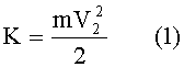
где К - кинетическая энергия воды, m - масса воды, V2 - скорость воды за винтом (стр.56, 1.43). Вот с этой кинетической энергией воды уносится полезная мощность судовых двигателей, которая могла бы превратиться в энергию движения судна, если бы масса воды, с которой взаимодействуют винты, была близка к массе судна. Однако при любых размерах винта довести массу воды, с которой винт обменивается импульсами движения, до таких величин невозможно.where K is the kinetic energy of water, m is the mass of water, V 2 is the water velocity behind the propeller (p. 56, 1.43). With this kinetic energy of water, the useful power of ship engines is carried away, which could turn into the energy of the ship’s movement if the mass of water with which the propellers interact was close to the mass of the ship. However, for any screw size, it is impossible to bring the mass of water with which the screw exchanges impulses of motion to such values.
В 19 веке предпринималась попытка заключить гребной винт в кожух или трубу и этим увеличить массу взаимодействующей с винтом воды. Этот эксперимент связывают с именем англичанина Ф.А.Брикса и утверждают, что применение таких кожухов не может дать положительного эффекта. Вместе с тем водометные движители, которые анализируются специалистами Ленинградского кораблестроительного института (ссылка дана выше) - это та же разновидность винта, помещенного в кожух или трубу. Проанализируем методом гидродинамики действие такого движителя.In the 19th century, an attempt was made to enclose a propeller in a casing or pipe and thereby increase the mass of water interacting with the screw. This experiment is associated with the name of the Englishman F.A. Brix and argues that the use of such casings cannot give a positive effect. At the same time, water-jet propulsors, which are analyzed by specialists of the Leningrad Shipbuilding Institute (link given above), are the same type of screw placed in a casing or pipe. Let us analyze the action of such a mover by the method of hydrodynamics.
Гидродинамика спокойное, т.е. установившееся движение воды в трубе, рассматривает как ламинарное течение (Физика, стр.112-113), для которого характерно послойное движение воды в трубе, при котором слои воды, прилегающие к стенкам трубы, рассматриваются как неподвижные, а максимальная скорость потока воды приходится в соответствии с формулой Пуазейля:Hydrodynamics is calm, i.e. the steady-state movement of water in the pipe is considered as a laminar flow (Physics, pp. 112-113), which is characterized by a layered movement of water in the pipe, in which the layers of water adjacent to the walls of the pipe are considered as motionless, and the maximum flow rate of water falls in according to the Poiseuille formula:

где R - радиус трубы, V - скорость воды, η - коэффициент вязкости воды, L - длина трубы, при r=0, где r - радиус минимального кольцевого слоя вдоль центральной оси трубы.where R is the radius of the pipe, V is the speed of water, η is the coefficient of viscosity of water, L is the length of the pipe, at r = 0, where r is the radius of the minimum annular layer along the central axis of the pipe.
Вторая формула Пуазейля описывает объемный расход воды через круглую трубу при ламинарном течении:The second Poiseuille formula describes the volumetric flow rate of water through a round pipe in a laminar flow:

где Q - объемный расход воды, R - радиус трубы, P1 и Р2 - давление на входе в трубу и на выходе из трубы, L - длина трубы, η - коэффициент вязкости воды. Здесь мы видим, что пропускная способность трубы при заданной разнице давлений на входе и выходе из трубы возрастает в четвертой степени от первоначальной, за счет увеличения радиуса трубы и только в линейной зависимости находится от длины трубы, т.е. при увеличении диаметра трубы в два раза ее пропускная способность возрастает в 16 раз. Из этого следует, что наличие кожуха вокруг движителя не может быть причиной отсутствия положительного эффекта.where Q is the volumetric flow rate of water, R is the radius of the pipe, P 1 and P 2 are the pressure at the inlet and outlet of the pipe, L is the length of the pipe, η is the coefficient of viscosity of water. Here we see that the pipe throughput at a given pressure difference at the inlet and outlet of the pipe increases to the fourth degree from the original, due to the increase in the radius of the pipe and is only linearly dependent on the length of the pipe, i.e. when the diameter of the pipe is doubled, its throughput increases by 16 times. From this it follows that the presence of a casing around the mover cannot be the reason for the lack of a positive effect.
Задачами изобретения являются: 1 - повышение коэффициента полезного действия движителя; 2 - обеспечение свободного реверсирования движения без остановки и переключения двигателей на обратный ход, без потерь энергии двигателей в редукторах при движении прямо.The objectives of the invention are: 1 - increase the efficiency of the propulsion device; 2 - ensuring free reversal of movement without stopping and switching motors to reverse, without loss of energy of motors in gearboxes when driving directly.
На основании (3) предлагается следующая конструкция судового гидромеханического движителя. Обратимся к фиг. 1. Здесь: 1 - корпус судна, 2 - ходовая турбина (их предлагается установить две вдоль вертикальной плоскости горизонтальной оси судна), 3 - направляющие блоки (по два с каждой турбиной), 4 - приводной вал турбины, 5 - задняя опора вала, 6 - ходовые рули, 7 - несущая палуба, 8-9 - защитные сетки на входе и выходе из турбин, 10 - воздушная камера под движителем, с функцией поплавка для балансирования тяжелой кормовой части, 11 - водозаборники вдоль боковых обводов кормовой части судна, 12 - обтекатели. Назначение водозаборников - увеличить массу воды, участвующую в обмене импульсами движения.Based on (3), the following design of a ship hydromechanical propulsion device is proposed. Turning to FIG. 1. Here: 1 - the hull of the vessel, 2 - the running turbine (it is proposed to install two along the vertical plane of the horizontal axis of the vessel), 3 - the guide blocks (two with each turbine), 4 - the drive shaft of the turbine, 5 - the rear shaft support, 6 - steering wheels, 7 - carrier deck, 8-9 - protective nets at the entrance and exit of the turbines, 10 - air chamber under the propulsion, with a float function for balancing the heavy stern, 11 - water intakes along the side outlines of the stern of the vessel, 12 - fairings. The purpose of the water intakes is to increase the mass of water involved in the exchange of momentum.
В современном судостроении наметилась тенденция постройки судов без передающих редукторов, в которых рабочий вал ходового двигателя напрямую, без всяких промежуточных редукторов, соединяется с ходовым винтом. В приведенной книге Ленинградских судостроителей приводится информация, что промежуточные редукторы на приводе ходовых винтов лишь на одном этапе преобразования частоты вращения сразу же понижают к.п.д. передачи на 2%. При этом там дается информация о том, что при понижении частоты вращения ходового винта возрастает к.п.д. движителя. Показатель к.п.д. водометных движителей еще раз подтверждает, что эффективность работы движителя напрямую связана со скоростью, с которой вода отбрасывается гребным винтом. С одной стороны, на основании второго закона Ньютона, чем выше ускорение, сообщаемое винтом воде, тем выше сила взаимодействия винта с водой, тем больше сила, движущая судно. Однако на основании (1), чем выше эта скорость, тем выше потери энергии двигателя.In modern shipbuilding, there has been a tendency to build ships without transmitting gears, in which the working shaft of the driving engine is directly connected to the lead screw without any intermediate gearboxes. The book of the Leningrad shipbuilders provides information that intermediate gearboxes on the drive of propellers only at one stage of converting the rotational speed immediately reduce the efficiency transmission by 2%. At the same time, information is given there that, when the rotor speed is reduced, the efficiency increases. mover. KPD water-jet propellers once again confirms that the propulsion efficiency is directly related to the speed at which water is thrown by the propeller. On the one hand, on the basis of Newton’s second law, the higher the acceleration reported by the propeller to water, the higher the force of interaction between the propeller and water, the greater the force moving the vessel. However, based on (1), the higher this speed, the higher the energy loss of the engine.
В предлагаемой конструкции движителя эта проблема не будет существенно влиять на потери энергии с кинетической энергией воды, поскольку масса воды здесь в десятки раз возрастет по сравнению с открытым гребным винтом и скорость протока воды через турбинный блок не будет определять эти потери напрямую. Здесь достаточно подобрать такую частоту вращения ходовых турбин, чтобы не происходило бессмысленного перемалывания воды, а конечная скорость протока воды через турбинные блоки была близка к скорости движения судна, вот тогда закон сохранения импульса обеспечит экономную работу движителя.In the proposed propulsion design, this problem will not significantly affect the energy loss with the kinetic energy of the water, since the mass of water here will increase tenfold compared to an open propeller and the speed of the water flow through the turbine unit will not directly determine these losses. It is enough to choose such a frequency of rotation of the running turbines so that there is no meaningless grinding of water, and the final speed of the water flow through the turbine blocks is close to the speed of the vessel, then the law of conservation of momentum will ensure the economical operation of the propulsion.
При всех недостатках в передаче движения от двигателей на гребные винты жесткая связь двигателей с винтами сопряжена с целым рядом трудностей; для реверсирования движения на судне останавливают двигатели, переключают их на обратный ход и запускают в другую сторону вращения. Предлагается техническое решение, которое устранит эти проблемы. Для этой цели между двигателем и винтом, или в данном случае турбинным блоком, может быть установлен дифференциальный реверс-редуктор. В основе такого редуктора может быть использовано техническое решение, применяемое в автомобилях при передаче вращения ведущим колесам. Известно, что на автомобиле через дифференциал ведущие колеса могут не только вращаться с разными скоростями, но, при затормаживании ручным тормозом, колеса могут вращаться в противоположные стороны.With all the shortcomings in the transmission of movement from engines to propellers, a rigid connection between engines and screws is associated with a number of difficulties; to reverse the movement on the vessel, the engines are stopped, they are switched to the reverse stroke and the rotation is started in the other direction. A technical solution is proposed that will eliminate these problems. For this purpose, between the engine and the propeller, or in this case a turbine unit, a differential reverse gear may be installed. At the heart of such a gearbox can be used the technical solution used in cars when transmitting rotation to drive wheels. It is known that on a car through the differential, the drive wheels can not only rotate at different speeds, but when braking with a hand brake, the wheels can rotate in opposite directions.
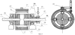
Обратимся к фиг.2. Здесь 13 - корпус редуктора, 14 - вал от двигателя, 15 - вал к ходовой турбине, 16 - шестерни валов, 17 - сателлиты, 18 - оси сателлитов, 19 - опорные подшипники реверс-редуктора, 20 - игольчатые подшипники опоры валов, 21 - тормозная лента блокировки вращения редуктора, 22 - фрикционные накладки тормозной ленты, 23 - основание крепления редуктора, 24 - муфта блокировки вала от двигателя, 25 - рычаг управления муфтой блокировки вала, 26 - кулачки блокировочной муфты вала (один корончатый венец выполнен на муфте, второй венец выполнен на торце ступицы корпуса реверс-редуктора), 27 - шлицевой венец на валу от двигателя и блокировочной муфте, 28 - механизм управления тормозным барабаном.Turn to figure 2. Here 13 is the gear housing, 14 is the shaft from the engine, 15 is the shaft to the running turbine, 16 are the gears of the shafts, 17 are the satellites, 18 are the axles of the satellites, 19 are the thrust bearings of the reverse gear, 20 are the needle bearings of the shaft support, 21 is brake belt for locking the rotation of the gearbox, 22 - friction linings of the brake belt, 23 - the base for attaching the gearbox, 24 - the coupling lock the shaft from the engine, 25 - the control lever of the coupling locking shaft, 26 - the cams of the locking shaft coupling (one crown ring is made on the coupling, the second the crown is made at the end of the hub of the housing reverse-re duct), 27 - splined crown on the shaft from the engine and the locking clutch, 28 - brake drum control mechanism.
Из фиг. 2 видно, что реверс-редуктор представляет собой компактный механизм, опирающийся через подшипники - 19 на основание - 23 и вращается на них как единая деталь. При прямом движении судна внутренние шестерни редуктора неподвижно относительно друг друга вращаются вместе с корпусом. Неподвижность шестерен обеспечивается блокировкой вала, идущего от двигателя, муфтой - 24, через шлицевой венец - 27 и торцевые, корончатые кулачки - 26. В этом состоянии механизма блокировочная муфта фиксирует внутренние шестерни редуктора и усилие вращения от двигателя жестко передается через неподвижные на своих осях сателлиты на шестерню и вал привода ходовой турбины. Для реверсирования движения судна не нужно останавливать двигатель и запускать его в другую сторону вращения, достаточно в момент снижения частоты вращения коленвала двигателя, когда снимается нагрузка на корончатые кулачки муфты блокировки, рычагом - 25 выключить муфту - 24, т.е. разъединить муфту - 24 с корончатыми кулачками корпуса редуктора и затянуть тормозную ленту - 21. Остановка корпуса реверс-редуктора заставит сателлиты - 17 проворачиваться относительно теперь уже неподвижных осей - 18, которые своим вращением приведут движение шестерни вала привода турбинного блока в противоположную сторону. Для возврата к движению в прежнем направлении достаточно растормозить ленту тормозного механизма и, подобрав частоту вращения коленчатого вала двигателя, заблокировать муфту - 24.From FIG. 2 shows that the reverse gear is a compact mechanism, supported through bearings - 19 on the base - 23 and rotates on them as a single part. In the direct movement of the vessel, the internal gears of the gearbox rotate motionless relative to each other with the hull. The immobility of the gears is ensured by blocking the shaft coming from the engine, the coupling - 24, through the splined crown - 27 and the end, crown cams - 26. In this state of the mechanism, the locking clutch fixes the internal gears of the gearbox and the rotation force from the engine is rigidly transmitted through the satellites fixed on their axes on the gear and drive shaft of the turbine drive. To reverse the movement of the vessel, it is not necessary to stop the engine and start it in the other direction of rotation, it is enough at the moment of lowering the engine crankshaft rotation speed when the load on the crown jaws of the locking clutch is removed, with the lever - 25 turn off the coupling - 24, i.e. disconnect the coupling - 24 with the crown cams of the gear housing and tighten the brake band - 21. Stopping the reverse gear housing will cause the satellites - 17 to rotate relative to the now stationary axes - 18, which will cause the rotation of the turbine drive shaft gear in the opposite direction. To return to the movement in the previous direction, it is enough to brake the brake band and, having picked up the engine speed, lock the clutch - 24.
Таким образом, можно будет управлять движением судна, не прибегая к остановкам двигателя, и легко комбинировать реверсивное движение одной ходовой турбины с прямым вращением другой для маневрирования на месте. Легко предположить, что для маневра достаточно оба руля повернуть круто в одном направлении, но тогда этот маневр приведет к повороту судна в движении, а реверсивная работа ходовых турбин обеспечит управление на месте, возле причала, и т.д. Применение такого редуктора не приведет к снижению к.п.д. всей передачи в целом, поскольку при движении прямо механизм редуктора не работает, а лишь вращается как одна деталь.Thus, it will be possible to control the movement of the vessel without resorting to engine stops, and it is easy to combine the reverse movement of one running turbine with the direct rotation of another for maneuvering in place. It is easy to assume that for both maneuvers it is enough to turn both wheels steeply in one direction, but then this maneuver will turn the vessel in motion, and the reverse operation of the running turbines will provide control in place, near the berth, etc. The use of such a gearbox will not lead to a decrease in efficiency the entire transmission as a whole, since when driving directly, the gear mechanism does not work, but only rotates as one part.
Сущность изобретения заключается в следующем: судовой гидромеханический движитель, отличающийся тем, что для повышения коэффициента полезного действия выполнен в виде одного или двух ходовых турбинных блоков в кормовой части судна, состоящих из ходовых турбин, размещенных на ходовых валах и двух, передних и задних, направляющих с обтекателями, вместе закрепленных в цилиндрических корпусах, установленных под дополнительной несущей палубой. Эти цилиндрические корпусы в передней части по бокам судна имеют раструбы, охватывающие сужающиеся боковые обводы кормовой части судна, заключающие в себе вместе с цилиндрическими корпусами объем воды, сопоставимый с массой корабля, при этом ходовые валы имеет вторую точку опоры на раскосах задней части движителя и на этих же раскосах крепятся ходовые рули. При двухтурбинном движителе между турбинами и ниже их выполняется пустотелая камера-поплавок, а боковые раструбы и задняя часть движителя имеют защитные сетки от попадания в турбинный блок льда и других механических предметов. Для обеспечения реверсивного привода ходовых турбинных блоков без остановки и переключения двигателей на обратный ход движитель выполнен так, что на валах, передающих вращение от двигателя на ходовые турбины, устанавливаются дифференциальные реверс-редукторы, которые могут быть как цилиндрическими, так и коническими, отличающиеся тем, что корпусы редукторов выполнены с тормозными механизмами вокруг цилиндрических тормозных барабанов, каковыми и являются корпусы, а на одном из полувалов, идущих к двигателю или ходовым турбинам, выполняется муфта блокировки, имеющая шлицевые венцы на полувалах и корончатые кулачковые венцы на муфтах и торцах ступиц корпуса реверс-редуктора.The invention consists in the following: a ship hydromechanical propulsion device, characterized in that in order to increase the efficiency, it is made in the form of one or two running turbine blocks in the stern of the vessel, consisting of running turbines located on the running shafts and two, front and rear guides with fairings, together fixed in cylindrical bodies, installed under an additional supporting deck. These cylindrical hulls in front of the sides of the vessel have sockets covering the narrowing side contours of the stern of the vessel, which together with the cylindrical hulls contain a volume of water comparable to the mass of the ship, while the shafts have a second fulcrum on the braces of the rear of the propulsion unit and running brackets are attached to the same braces. With a two-turbine propulsion device, a hollow float chamber is made between and below the turbines, and the side sockets and the rear part of the propulsion device have protective nets against ice and other mechanical objects entering the turbine unit. To ensure the reversible drive of the running turbine blocks without stopping and switching the engines to the reverse stroke, the propulsion device is designed so that differential shafts are installed on the shafts that transmit rotation from the engine to the running turbines, which can be either cylindrical or bevel, characterized in that that the gear cases are made with braking mechanisms around the cylindrical brake drums, which are the bodies, and on one of the half-shafts going to the engine or running turbines, etsya lockup clutch having a spline and crowns Stubshaft crown cam crowns of the sleeves and the ends of the hub shell reverse gear.
В школьном учебнике физики А.В.Перышкина (учпедгиз, 1969 г., ч. 2) приводится информация, что напорные гидротурбины в системе гидроэнергетики работают с к.п.д. более 90%. Предлагаемый движитель, в силу необходимости реверсирования движения корабля, должен одинаково успешно двигать судно в обоих направлениях, поэтому ходовая турбина здесь должна быть выполнена с симметричными лопастями, при этом здесь не будет никакой необходимости в изменении шага лопастей и угла атаки, кроме того, наличие направляющих блоков должно максимально снижать эффект турбуленции в движении воды через движитель, а по эффективности работы такой движитель будет близок к к.п.д. напорных гидротурбин. Судно с таким движителем в морских просторах будет двигаться, как гидравлическая ракета. Разгон судна до крейсерской скорости будет протекать гораздо быстрее обычного и гораздо экономнее.In the school textbook of physics of A.V. Peryshkin (uchpedgiz, 1969, part 2), information is given that pressure-driven hydraulic turbines in the hydropower system work with efficiency more than 90%. The proposed propulsion, due to the need to reverse the movement of the ship, should equally successfully move the vessel in both directions, therefore, the running turbine here must be made with symmetrical blades, while there will be no need to change the pitch of the blades and the angle of attack, in addition, the presence of guides units should minimize the effect of turbulence in the movement of water through the mover, and in terms of operating efficiency, such mover will be close to the efficiency pressure turbines. A vessel with such a mover in the open sea will move like a hydraulic rocket. Acceleration of the vessel to cruising speed will proceed much faster than usual and much more economical.
Технология изготовления устройства по заявленному изобретению не потребует больших доработок имеющихся технологий производства.The manufacturing technology of the device according to the claimed invention will not require large modifications of existing production technologies.
Claims (2)
Priority Applications (1)
| Application Number | Priority Date | Filing Date | Title |
|---|---|---|---|
| RU2012105191/11A RU2492103C1 (en) | 2012-02-14 | 2012-02-14 | Marine hydromechanical propulsor |
Applications Claiming Priority (1)
| Application Number | Priority Date | Filing Date | Title |
|---|---|---|---|
| RU2012105191/11A RU2492103C1 (en) | 2012-02-14 | 2012-02-14 | Marine hydromechanical propulsor |
Publications (2)
| Publication Number | Publication Date |
|---|---|
| RU2012105191A RU2012105191A (en) | 2013-08-20 |
| RU2492103C1 true RU2492103C1 (en) | 2013-09-10 |
Family
ID=49162554
Family Applications (1)
| Application Number | Title | Priority Date | Filing Date |
|---|---|---|---|
| RU2012105191/11A RU2492103C1 (en) | 2012-02-14 | 2012-02-14 | Marine hydromechanical propulsor |
Country Status (1)
| Country | Link |
|---|---|
| RU (1) | RU2492103C1 (en) |
Citations (3)
| Publication number | Priority date | Publication date | Assignee | Title |
|---|---|---|---|---|
| US6238257B1 (en) * | 1998-10-30 | 2001-05-29 | Bird-Johnson Company | Surface vessel with a waterjet propulsion system |
| RU53261U1 (en) * | 2005-11-29 | 2006-05-10 | Виктор Тимофеевич Нестратов | SHIP MARINE INSTALLATION |
| US20090137165A1 (en) * | 2005-07-20 | 2009-05-28 | Welker, Inc. | Newtonian thrust cowl array |
-
2012
- 2012-02-14 RU RU2012105191/11A patent/RU2492103C1/en not_active IP Right Cessation
Patent Citations (3)
| Publication number | Priority date | Publication date | Assignee | Title |
|---|---|---|---|---|
| US6238257B1 (en) * | 1998-10-30 | 2001-05-29 | Bird-Johnson Company | Surface vessel with a waterjet propulsion system |
| US20090137165A1 (en) * | 2005-07-20 | 2009-05-28 | Welker, Inc. | Newtonian thrust cowl array |
| RU53261U1 (en) * | 2005-11-29 | 2006-05-10 | Виктор Тимофеевич Нестратов | SHIP MARINE INSTALLATION |
Also Published As
| Publication number | Publication date |
|---|---|
| RU2012105191A (en) | 2013-08-20 |
Similar Documents
| Publication | Publication Date | Title |
|---|---|---|
| US10392089B2 (en) | Contra-rotating propulsor for marine propulsion | |
| US20080089786A1 (en) | Counter-Rotating Integrated Propeller Assembly | |
| US3389558A (en) | Jet propulsion apparatus | |
| Dang et al. | The Wageningen C-and D-series propellers | |
| CN103600824B (en) | A kind of marine propeller | |
| US6361387B1 (en) | Marine propulsion apparatus with dual driveshafts extending from a forward end of an engine | |
| EP0246609B1 (en) | Counter-rotating propellers | |
| RU2119875C1 (en) | Shipboard propeller-engine plant, type swivel column | |
| EP3551530B1 (en) | Strut mounted gear box for counter rotating propellers | |
| CN101314405A (en) | Multilevel double-circular arc gear pump for water jet propeller of ship | |
| EP0898548B1 (en) | Marine propulsion system | |
| JP2023099917A (en) | Pod type propulsion device | |
| Pasetto et al. | A new proposal of a vertical axis propeller | |
| CN109665081A (en) | A kind of all-rotation thrust unit suitable for tearing platform test open | |
| CN107284639B (en) | An adjustable multi-shaft water jet propulsion ship model propulsion shafting transfer device | |
| WO1998057848A1 (en) | Contra-rotating ducted impellers | |
| Mulford | Development and impact of the evsp: an intelligent propulsion system for safe, sustainable and efficient navigation | |
| RU150293U1 (en) | CARGO SHIP WITH MULTIFUNCTIONAL TWO-STAGE VEHICLE MOTOR | |
| RU2586180C2 (en) | Propulsor, disc craft, disc craft large carrying capacity, underwater lift-pusher, propulsor underwater vehicles | |
| RU2523862C1 (en) | Highly protected versatile ship propeller | |
| US1905162A (en) | Stern paddle-wheel propulsion mechanism for boats | |
| GB2179014A (en) | Improvements in propulsion systems | |
| Schlappi | An innovative energy saving propulsion system for naval ships | |
| SU994339A1 (en) | Ship for moving against river stream | |
| Kushnir et al. | Optimization of marine thrusters |
Legal Events
| Date | Code | Title | Description |
|---|---|---|---|
| MM4A | The patent is invalid due to non-payment of fees |
Effective date: 20180215 |