RU2492490C1 - Sensing element of micromechanical accelerometer - Google Patents
Sensing element of micromechanical accelerometer Download PDFInfo
- Publication number
- RU2492490C1 RU2492490C1 RU2011152062/28A RU2011152062A RU2492490C1 RU 2492490 C1 RU2492490 C1 RU 2492490C1 RU 2011152062/28 A RU2011152062/28 A RU 2011152062/28A RU 2011152062 A RU2011152062 A RU 2011152062A RU 2492490 C1 RU2492490 C1 RU 2492490C1
- Authority
- RU
- Russia
- Prior art keywords
- elastic elements
- pendulum
- bending elastic
- inertial mass
- cross
- Prior art date
Links
- 238000005452 bending Methods 0.000 claims abstract description 16
- 239000011521 glass Substances 0.000 claims abstract description 15
- 239000000758 substrate Substances 0.000 claims abstract description 15
- 229910021421 monocrystalline silicon Inorganic materials 0.000 claims abstract description 6
- 230000001133 acceleration Effects 0.000 abstract description 10
- 238000010348 incorporation Methods 0.000 abstract 1
- 239000000126 substance Substances 0.000 abstract 1
- VYPSYNLAJGMNEJ-UHFFFAOYSA-N Silicium dioxide Chemical compound O=[Si]=O VYPSYNLAJGMNEJ-UHFFFAOYSA-N 0.000 description 5
- 238000006073 displacement reaction Methods 0.000 description 5
- 238000005259 measurement Methods 0.000 description 5
- 238000004519 manufacturing process Methods 0.000 description 3
- 230000035945 sensitivity Effects 0.000 description 3
- 230000007423 decrease Effects 0.000 description 2
- 230000003247 decreasing effect Effects 0.000 description 2
- 238000013461 design Methods 0.000 description 2
- 239000005350 fused silica glass Substances 0.000 description 2
- 238000000034 method Methods 0.000 description 2
- 239000010453 quartz Substances 0.000 description 2
- 239000003351 stiffener Substances 0.000 description 2
- XUIMIQQOPSSXEZ-UHFFFAOYSA-N Silicon Chemical compound [Si] XUIMIQQOPSSXEZ-UHFFFAOYSA-N 0.000 description 1
- 238000004132 cross linking Methods 0.000 description 1
- 238000009826 distribution Methods 0.000 description 1
- 238000009434 installation Methods 0.000 description 1
- 230000007935 neutral effect Effects 0.000 description 1
- 230000008092 positive effect Effects 0.000 description 1
- 238000012545 processing Methods 0.000 description 1
- 229910052710 silicon Inorganic materials 0.000 description 1
- 239000010703 silicon Substances 0.000 description 1
- 239000000725 suspension Substances 0.000 description 1
- 238000012360 testing method Methods 0.000 description 1
- 238000012549 training Methods 0.000 description 1
Images
Landscapes
- Pressure Sensors (AREA)
- Micromachines (AREA)
Abstract
Description
Изобретение относится к измерительной технике и может применяться в микромеханических датчиках линейных ускорений.The invention relates to measuring technique and can be used in micromechanical linear acceleration sensors.
Известен чувствительный элемент микромеханического акселерометра, выполненный из плавленого кварца в форме прямоугольной рамки, преобразователя перемещений рамки, регистрирующего поворот кварцевой рамки в зависимости от измеряемого ускорения [1].A known element of a micromechanical accelerometer made of fused quartz in the form of a rectangular frame, a frame displacement transducer, detecting the rotation of the quartz frame depending on the measured acceleration [1].
Недостатком этого устройства является сложность конструкции, низкая технологичность, низкая точность из-за чувствительности к перекрестным связям. Изготовление таких устройств из плавленого кварца возможно только в единичном производстве и требует специальной высококвалифицированной подготовки персонала. Трудоемкая реализация преобразователя перемещений так как установка в корпус кварцевой рамки возможна только раздельно от преобразователя перемещений и требует затем отдельной регулировки положения рамки в зазоре преобразователя перемещений, то есть установки ее в нулевое положение.The disadvantage of this device is the design complexity, low adaptability, low accuracy due to sensitivity to cross-linking. The manufacture of such devices from fused quartz is possible only in a single production and requires special highly qualified personnel training. The time-consuming implementation of the displacement transducer since installation of a quartz frame in the housing is possible only separately from the displacement transducer and then requires a separate adjustment of the position of the frame in the gap of the displacement transducer, that is, setting it to zero.
Известен чувствительный элемент микромеханического акселерометра, выполненный из монокристаллического кремния в виде электропроводящей инерционной массы, представляющей собой маятник, имеющий два плеча и подвешенный с помощью торсионов, внешнюю рамку, к которой одной стороной соединены торсионы, стеклянную подложку (основание), на которую крепится внешняя рамка, торсионы выполнены крестообразными с поперечным сечением в виде Х-образного профиля, ось симметрии фигуры инерционной массы совмещена с осью, проходящей через торсионы подвеса, а маятниковый подвес обеспечен удалением части одного плеча инерционной массы на его поверхности, при этом указанная поверхность выполнена с ребрами жесткости, причем профиль поперечного сечения ребер жесткости имеет Т-образную форму, а наклонные грани крестообразных торсионов с профилем поперечного сечения в виде Х-образной формы ориентированы по направлению (111) кристаллографической решетки монокристаллического кремния. [2]A sensitive element of a micromechanical accelerometer is known, made of single-crystal silicon in the form of an electrically conductive inertial mass, which is a pendulum having two arms and suspended using torsion bars, an external frame to which torsion bars are connected to one side, a glass substrate (base) to which the external frame is attached , torsion bars are made cross-shaped with a cross section in the form of an X-shaped profile, the axis of symmetry of the figure of the inertial mass is aligned with the axis passing through the torsion bars ca, and the pendulum suspension is provided by removing part of one shoulder of the inertial mass on its surface, while this surface is made with stiffeners, the cross-sectional profile of the stiffeners being T-shaped, and the inclined faces of the cross-shaped torsion bars with a cross-sectional profile in the form of X- shaped are oriented in the direction (111) of the crystallographic lattice of single-crystal silicon. [2]
Одним из недостатков известного датчика является высокая чувствительность к температурным воздействиям. При повышении или понижении рабочих температур торсионы чувствительного элемента удлиняются или укорачиваются, соответственно. Так как торсионы жестко соединены, с одной стороны, с внешней рамкой, с другой стороны, с инерционной массой, при этом внешняя рамка жестко соединена со стеклянной подложкой (основанием), то возникающая при этом деформация приложена к инерционной массе, которая закручивает последнюю. При этом в отсутствие приложенного ускорения возникает сигнал, то есть нулевой сигнал, который увеличивается при увеличении, уменьшении уровня температуры. Кроме того из-за технологического разброса изготовления чувствительного элемента, а именно торсионов, появляется нестабильность нулевого сигнала. Из всего этого следует, что точность измерения параметра, а именно линейного ускорения, существенно уменьшается.One of the disadvantages of the known sensor is its high sensitivity to temperature influences. With increasing or decreasing operating temperatures, the torsions of the sensing element lengthen or shorten, respectively. Since the torsion bars are rigidly connected, on the one hand, with the outer frame, on the other hand, with the inertial mass, while the outer frame is rigidly connected with the glass substrate (base), the resulting strain is applied to the inertial mass, which twists the latter. In this case, in the absence of applied acceleration, a signal occurs, that is, a zero signal, which increases with increasing, decreasing temperature level. In addition, due to the technological variation in the manufacture of the sensitive element, namely the torsion bars, instability of the zero signal appears. From all this it follows that the accuracy of the parameter measurement, namely linear acceleration, is significantly reduced.
Другим недостатком является высокая чувствительность конструкции чувствительного элемента продольным и поперечным вибрациям, направленных по осям X и Y и под углом к ним. Это существенным образом влияет на стабильность нулевого сигнала и точность измерения самого параметра, то есть линейного ускорения.Another disadvantage is the high sensitivity of the design of the sensing element to longitudinal and transverse vibrations directed along the axes X and Y and at an angle to them. This significantly affects the stability of the zero signal and the accuracy of the measurement of the parameter itself, that is, linear acceleration.
Так при воздействии вибрации по этим осям или под углом к ним, возникают объемные волновые процессы в торсионах, последние представляют собой, в первом приближении, стержни. Объемная волна в торсионах вызывает время-переменную деформацию в электропроводящей инерционной массе, являющуюся частью преобразователя перемещений. В результате чего на выходе датчика увеличивается смещение нуля и, как следствие, понижается точность прибора в целом.So when exposed to vibration along these axes or at an angle to them, volumetric wave processes occur in the torsion bars, the latter being, in a first approximation, rods. A body wave in torsions causes a time-variable deformation in an electrically conductive inertial mass, which is part of the displacement transducer. As a result, the zero offset increases at the sensor output and, as a result, the accuracy of the device as a whole decreases.
Задачей, на решение которой направлено изобретение, является увеличение точности измерения.The problem to which the invention is directed, is to increase the accuracy of measurement.
Для достижения этого в чувствительном элементе микромеханического акселерометра, содержащем маятник из монокристаллического кремния, стеклянную подложку и внешнюю рамку с площадками крепления к стеклянной подложке, крестообразные торсионы, согласно заявленному решению, дополнительно введена центральная площадка крепления к стеклянной подложке, расположенная в центре симметрии маятника, соединенная через изгибные упругие элементы с маятником таким образом, что ось изгиба упругих элементов совпадает с осью крутильных крестообразных торсионов, и между местом крепления конца торсиона в маятнике и изгибными упругими элементами, вдоль маятника, расположена сквозная щель, с обеих сторон относительно центральной площадки крепления.To achieve this, in the sensitive element of the micromechanical accelerometer containing a single-crystal silicon pendulum, a glass substrate and an external frame with attachment areas to the glass substrate, cruciform torsion bars, according to the claimed solution, an additional central attachment area to the glass substrate located at the center of symmetry of the pendulum connected through bending elastic elements with a pendulum in such a way that the axis of bending of the elastic elements coincides with the axis of torsional cross-shaped x torsion bars, and between the point of attachment of the end of the torsion bar in the pendulum and flexural elastic elements, a through slit is located along the pendulum, on both sides relative to the central mounting platform.
Признаком, отличающим предложенный чувствительный элемент от известного является то, что в чувствительном элементе дополнительно введена центральная площадка крепления к стеклянной подложке, расположенная в центре симметрии инерционной массы и соединенная с ней через изгибные упругие элементы, ось изгиба которых совпадает с осью крутильных крестообразных торсионов. В центральной точке закрепления механические напряжения равны нулю при всех видах колебаний. В точке крепления и вблизи ее с учетом линейного закона распределения механических напряжений и деформаций напряженное состояние отсутствует. Поэтому при воздействии продольной вибрации вдоль осей Х и У или под углом к ним дополнительно введенные изгибные элементы, одной стороной связанные с центральной точкой крепления к стеклянной подложке, а другой- с инерционной массой что, существенно уменьшают деформацию инерционной массы, тем самым уменьшая погрешность измерения. Другим существенным признаком является то, что в теле инерционной массы вытравлены сквозные щели. Все это, в целом, увеличивает точность измерения полезного сигнала.A feature that distinguishes the proposed sensitive element from the known one is that a central attachment area to the glass substrate is additionally introduced in the sensitive element, located in the center of symmetry of the inertial mass and connected to it through bending elastic elements, the bending axis of which coincides with the axis of the torsion cross-shaped torsion bars. At the central fixing point, mechanical stresses are equal to zero for all types of vibrations. At the attachment point and near it, taking into account the linear law of the distribution of mechanical stresses and strains, the stress state is absent. Therefore, under the influence of longitudinal vibration along the X and Y axes or at an angle to them, additionally introduced bending elements connected on one side to the central point of attachment to the glass substrate and the other on the inertial mass, which significantly reduce the deformation of the inertial mass, thereby reducing the measurement error . Another significant sign is that through the slits are etched in the body of the inertial mass. All this, in general, increases the accuracy of the measurement of the useful signal.
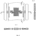
Предложенный микромеханический датчик иллюстрируется чертежами, представленными на фиг.1, 2. На фиг.1 изображен кремниевый чувствительный элемент в плане, где:The proposed micromechanical sensor is illustrated by the drawings shown in figures 1, 2. Figure 1 shows a silicon sensor in plan, where:
1 - центральная площадка крепления к стеклянной подложке (не показана);1 - a central mounting pad to a glass substrate (not shown);
2 - инерционная масса;2 - inertial mass;
3 - изгибные упругие элементы;3 - bending elastic elements;
4 - крестообразные торсионы;4 - cruciform torsion bars;
5 - сквозные щели;5 - through slits;
6 - внешняя рамка;6 - outer frame;
7 - площадки крепления на внешней рамке.7 - mounting pads on the outer frame.
На фиг.2, центральная часть чувствительного элемента в увеличенном виде, а также сечение по A-A и B-B.Figure 2, the Central part of the sensing element in an enlarged view, as well as a section along A-A and B-B.
Чувствительный элемент, выполненный из монокристаллического кремния низкой проводимости содержит центральную площадку 1, соединенную со стеклянной подложкой (не показано), на которых находятся электроды (не показано) емкостного преобразователя, внешнюю рамку 6 с площадками крепления 7, соединенную с инерционной массой 2, через крестообразные торсионы 4. Центральная площадка 1 соединена с инерционной массой 2 через изгибные упругие элементы 3. Между местом крепления конца крестообразного торсиона 4 в инерционной массе (маятнике) 2 и изгибными упругими элементами 3, вдоль инерционной массы (маятника) 2, расположена сквозная щель 5, с обеих сторон относительно центральной площадки крепления 1.The sensitive element made of single-crystal silicon of low conductivity contains a central platform 1 connected to a glass substrate (not shown), on which there are electrodes (not shown) of a capacitive transducer, an external frame 6 with attachment pads 7 connected to an inertial mass 2 through crosswise torsion bars 4. The central platform 1 is connected to the inertial mass 2 through bending elastic elements 3. Between the attachment point of the end of the cruciform torsion 4 in the inertial mass (pendulum) 2 and the bending and elastic elements 3, along the inertial mass (pendulum) 2, there is a through slot 5, on both sides relative to the central mounting platform 1.
Чувствительный элемент работает следующим образом. При воздействии линейного ускорения маятник 2, отклоняется от своего нейтрального положения. При этом крестообразные торсионы 4 закручиваются на определенный угол. На стеклянных подложках и маятнике 2 реализована схема обработки сигнала. При воздействии линейного ускорения возникает дисбаланс между верхом и низом, со стороны стеклянных подложек. Величина этого дисбаланса пропорциональна измеряемому ускорению.The sensitive element operates as follows. When exposed to linear acceleration, the pendulum 2 deviates from its neutral position. While the cruciform torsion bars 4 are twisted at a certain angle. On glass substrates and pendulum 2, a signal processing circuit is implemented. When exposed to linear acceleration, an imbalance occurs between the top and bottom, on the side of the glass substrates. The magnitude of this imbalance is proportional to the measured acceleration.
При воздействии вредных факторов введение центральной площадки крепления 1 и дополнительных изгибных упругих элементов 3 резко уменьшает нулевой сигнал и его нестабильность, а при одновременном воздействии еще измеряемого ускорения уменьшается погрешность крутизны характеристики прибора в целом. Введение сквозных щелей 5 значительно уменьшает деформацию, передающуюся на крестообразные торсионы 4 и изгибные упругие элементы 3 при воздействии плюсовых и отрицательных температур. Это уменьшает нулевой сигнал и уменьшает погрешность крутизны характеристики датчика в целом.Under the influence of harmful factors, the introduction of a central mounting pad 1 and additional bending elastic elements 3 sharply reduces the zero signal and its instability, and with the simultaneous action of measured acceleration, the error of the slope of the characteristics of the device as a whole decreases. The introduction of through slots 5 significantly reduces the deformation transmitted to the cruciform torsion 4 and flexural elastic elements 3 when exposed to positive and negative temperatures. This reduces the zero signal and reduces the error of the slope of the characteristic of the sensor as a whole.
Проведенные математическое моделирование в среде ANSYS и макетные испытания показали положительный эффект данного устройства и по технологичности и по точности по сравнению с прототипом.Conducted mathematical modeling in the ANSYS environment and prototype tests showed a positive effect of this device in terms of manufacturability and accuracy compared to the prototype.
Источники информации:Information sources:
1. Мельников В.Е. «Электромеханические преобразователи на базе кварцевого стекла». Москва, Машиностроение, 1984 г.1. Melnikov V.E. "Electromechanical converters based on quartz glass." Moscow, Engineering, 1984
2. Патент РФ №2251702 (прототип).2. RF patent No. 2251702 (prototype).
Claims (1)
Priority Applications (1)
| Application Number | Priority Date | Filing Date | Title |
|---|---|---|---|
| RU2011152062/28A RU2492490C1 (en) | 2011-12-21 | 2011-12-21 | Sensing element of micromechanical accelerometer |
Applications Claiming Priority (1)
| Application Number | Priority Date | Filing Date | Title |
|---|---|---|---|
| RU2011152062/28A RU2492490C1 (en) | 2011-12-21 | 2011-12-21 | Sensing element of micromechanical accelerometer |
Publications (2)
| Publication Number | Publication Date |
|---|---|
| RU2011152062A RU2011152062A (en) | 2013-06-27 |
| RU2492490C1 true RU2492490C1 (en) | 2013-09-10 |
Family
ID=48701088
Family Applications (1)
| Application Number | Title | Priority Date | Filing Date |
|---|---|---|---|
| RU2011152062/28A RU2492490C1 (en) | 2011-12-21 | 2011-12-21 | Sensing element of micromechanical accelerometer |
Country Status (1)
| Country | Link |
|---|---|
| RU (1) | RU2492490C1 (en) |
Cited By (2)
| Publication number | Priority date | Publication date | Assignee | Title |
|---|---|---|---|---|
| RU2746763C1 (en) * | 2020-09-15 | 2021-04-20 | Акционерное общество "Инерциальные технологии "Технокомплекса" (АО "ИТТ") | Micromechanical accelerometer |
| RU2753475C1 (en) * | 2020-09-15 | 2021-08-17 | Акционерное общество "Инерциальные технологии "Технокомплекса" (АО "ИТТ") | Micromechanical accelerometer |
Citations (6)
| Publication number | Priority date | Publication date | Assignee | Title |
|---|---|---|---|---|
| EP0311484A2 (en) * | 1987-10-02 | 1989-04-12 | Sextant Avionique S.A. | Flat acceleration sensor with a pendulum piece |
| US5126812A (en) * | 1990-02-14 | 1992-06-30 | The Charles Stark Draper Laboratory, Inc. | Monolithic micromechanical accelerometer |
| RU2231795C1 (en) * | 2002-12-10 | 2004-06-27 | Открытое акционерное общество Арзамасское научно-производственное предприятие "Темп-Авиа" | Sensitive element of integrated accelerometer |
| RU2251702C1 (en) * | 2004-07-02 | 2005-05-10 | Государственное образовательное учреждение высшего профессионального образования "Московский государственный институт электронной техники (технический университет)" (МИЭТ) | Micromechanical accelerometer |
| RU2379694C1 (en) * | 2008-10-16 | 2010-01-20 | Московский государственный институт электронной техники (технический университет) | Micromechanical linear accelerometre |
| RU2379693C1 (en) * | 2008-10-16 | 2010-01-20 | Московский государственный институт электронной техники (технический университет) | Sensitive element of integral accelerometre |
-
2011
- 2011-12-21 RU RU2011152062/28A patent/RU2492490C1/en active IP Right Revival
Patent Citations (6)
| Publication number | Priority date | Publication date | Assignee | Title |
|---|---|---|---|---|
| EP0311484A2 (en) * | 1987-10-02 | 1989-04-12 | Sextant Avionique S.A. | Flat acceleration sensor with a pendulum piece |
| US5126812A (en) * | 1990-02-14 | 1992-06-30 | The Charles Stark Draper Laboratory, Inc. | Monolithic micromechanical accelerometer |
| RU2231795C1 (en) * | 2002-12-10 | 2004-06-27 | Открытое акционерное общество Арзамасское научно-производственное предприятие "Темп-Авиа" | Sensitive element of integrated accelerometer |
| RU2251702C1 (en) * | 2004-07-02 | 2005-05-10 | Государственное образовательное учреждение высшего профессионального образования "Московский государственный институт электронной техники (технический университет)" (МИЭТ) | Micromechanical accelerometer |
| RU2379694C1 (en) * | 2008-10-16 | 2010-01-20 | Московский государственный институт электронной техники (технический университет) | Micromechanical linear accelerometre |
| RU2379693C1 (en) * | 2008-10-16 | 2010-01-20 | Московский государственный институт электронной техники (технический университет) | Sensitive element of integral accelerometre |
Non-Patent Citations (1)
| Title |
|---|
| РАСПОПОВ В.Я. Микромеханические приборы. - М.: Машиностроение, 2007, с.27-31. * |
Cited By (2)
| Publication number | Priority date | Publication date | Assignee | Title |
|---|---|---|---|---|
| RU2746763C1 (en) * | 2020-09-15 | 2021-04-20 | Акционерное общество "Инерциальные технологии "Технокомплекса" (АО "ИТТ") | Micromechanical accelerometer |
| RU2753475C1 (en) * | 2020-09-15 | 2021-08-17 | Акционерное общество "Инерциальные технологии "Технокомплекса" (АО "ИТТ") | Micromechanical accelerometer |
Also Published As
| Publication number | Publication date |
|---|---|
| RU2011152062A (en) | 2013-06-27 |
Similar Documents
| Publication | Publication Date | Title |
|---|---|---|
| CN103941041B (en) | A kind of single mass three-shaft mems accelerometer of three-frame structure | |
| EP3421959B1 (en) | Multi-axial force sensor, method of manufacturing the multi-axial force sensor, and method for operating the multi-axial force sensor | |
| CN205562088U (en) | Quartzy resonance power of integral type is sensing element and dynamometry module frequently | |
| WO2014169540A1 (en) | Non-uniform cross section cantilever beam piezoelectricity acceleration sensor | |
| CN104820113A (en) | Quartz dual-beam force-frequency resonator integrated with temperature sensitive unit | |
| RU2632264C1 (en) | Sensor with mobile sensitive component working in mixed vibration and pendular mode, and methods of controlling such sensor | |
| US20110100125A1 (en) | Acceleration sensor | |
| CN111812355A (en) | A low stress sensitivity silicon microresonant accelerometer structure | |
| CN103235155A (en) | Piezoresistive acceleration sensor with full-bridge micro-beam structure | |
| KR20100074189A (en) | Vibrating micromechanical sensor of angular velocity | |
| RU154143U1 (en) | SENSITIVE ELEMENT OF A MICROMECHANICAL ACCELEROMETER | |
| RU2492490C1 (en) | Sensing element of micromechanical accelerometer | |
| Zou et al. | Micro-electro-mechanical resonant tilt sensor with 250 nano-radian resolution | |
| CN110095633B (en) | Micro-resonance accelerometer with on-chip temperature control function and micro-resonance device | |
| RU138627U1 (en) | SENSITIVE ELEMENT OF A MICROMECHANICAL ACCELEROMETER | |
| RU2251702C1 (en) | Micromechanical accelerometer | |
| RU106001U1 (en) | MICROMECHANICAL SENSOR | |
| Zou et al. | Micro-electro-mechanical resonant tilt sensor | |
| RU131194U1 (en) | SENSITIVE ELEMENT OF A MICROMECHANICAL ACCELEROMETER | |
| RU170862U1 (en) | SENSITIVE SENSOR OF A SHOCK SENSOR | |
| RU2324192C1 (en) | Double beamed accelerometer | |
| RU131195U1 (en) | MICROMECHANICAL SENSOR | |
| RU2840118C1 (en) | Sensitive element of micromechanical sensor | |
| JP2008304409A (en) | Acceleration detection unit and acceleration sensor | |
| RU2387999C1 (en) | Multibeam accelerometre - analyzer of mechanical oscillations spectrum based on piezoresistive converters |
Legal Events
| Date | Code | Title | Description |
|---|---|---|---|
| MM4A | The patent is invalid due to non-payment of fees |
Effective date: 20131222 |
|
| NF4A | Reinstatement of patent |
Effective date: 20150427 |
|
| PD4A | Correction of name of patent owner |