RU2496551C2 - Inertial thickener of sludgy materials - Google Patents
Inertial thickener of sludgy materials Download PDFInfo
- Publication number
- RU2496551C2 RU2496551C2 RU2012103110/05A RU2012103110A RU2496551C2 RU 2496551 C2 RU2496551 C2 RU 2496551C2 RU 2012103110/05 A RU2012103110/05 A RU 2012103110/05A RU 2012103110 A RU2012103110 A RU 2012103110A RU 2496551 C2 RU2496551 C2 RU 2496551C2
- Authority
- RU
- Russia
- Prior art keywords
- helical
- housing
- casing
- separation
- spring
- Prior art date
Links
- 239000002562 thickening agent Substances 0.000 title claims abstract description 12
- 239000000463 material Substances 0.000 title claims description 14
- 239000000706 filtrate Substances 0.000 claims abstract description 5
- 230000015572 biosynthetic process Effects 0.000 claims description 3
- 239000002245 particle Substances 0.000 abstract description 12
- XLYOFNOQVPJJNP-UHFFFAOYSA-N water Substances O XLYOFNOQVPJJNP-UHFFFAOYSA-N 0.000 abstract description 10
- 238000000926 separation method Methods 0.000 abstract description 8
- 230000006835 compression Effects 0.000 abstract description 2
- 238000007906 compression Methods 0.000 abstract description 2
- 239000007789 gas Substances 0.000 abstract description 2
- 239000000126 substance Substances 0.000 abstract description 2
- 238000010327 methods by industry Methods 0.000 abstract 1
- 239000010802 sludge Substances 0.000 description 7
- 238000000034 method Methods 0.000 description 4
- 239000007788 liquid Substances 0.000 description 2
- 230000018044 dehydration Effects 0.000 description 1
- 238000006297 dehydration reaction Methods 0.000 description 1
- 238000004519 manufacturing process Methods 0.000 description 1
- 239000002994 raw material Substances 0.000 description 1
- 238000007670 refining Methods 0.000 description 1
- 239000013598 vector Substances 0.000 description 1
- 238000003466 welding Methods 0.000 description 1
Images

Landscapes
- Treatment Of Sludge (AREA)
- Centrifugal Separators (AREA)
- Cyclones (AREA)
Abstract
Description
Изобретение относится к технике отделения дисперсных частиц, например ила, от воды с использованием гравитационных инерционных или центробежных сил, создаваемых поворотом потока воды с илом, и может быть использовано для отделение дисперсных частиц от газов или паров в энергетике, нефтеперерабатывающей, нефтехимической и химической промышленности, а также в пищевой промышленности, например, для обезвоживания сырья при производстве пиктина.The invention relates to techniques for separating dispersed particles, for example sludge, from water using gravitational inertial or centrifugal forces created by turning a stream of water with sludge, and can be used to separate dispersed particles from gases or vapors in the energy, oil refining, petrochemical and chemical industries, as well as in the food industry, for example, for dehydration of raw materials in the production of pictin.
Известен инерционный сгуститель (а.с. SU №1389815, кл. В01Д 33/02, 1988 г.), включающий корпус с установленным в нем цилиндрическим фильтром, входной патрубок, винтовую вставку и патрубки для отвода фильтрата и сгущенной фракции.A known inertial thickener (a.s. SU No. 1389815, class V01D 33/02, 1988), comprising a housing with a cylindrical filter installed in it, an inlet pipe, a screw insert and pipes for draining the filtrate and condensed fraction.
Недостатком известной конструкции является недостаточная эффективность, высокое гидравлическое сопротивление и ограниченные технологические возможности.A disadvantage of the known design is the lack of efficiency, high hydraulic resistance and limited technological capabilities.
Техническим решением является расширение технологических возможностей, повышение эффективности отделения дисперсных илистых частиц от жидкости.The technical solution is the expansion of technological capabilities, increasing the efficiency of separation of dispersed silt particles from the liquid.
Поставленная задача достигается тем, что в инерционном сгустителе илистых материалов, содержащем корпус, входной патрубок, патрубки для отвода фильтрата и сгущенной фракции, корпус выполнен винтовым многозаходным пустотелым из полос прямоугольной формы, свернутых в вертикальной плоскости в продольном направлении и изогнутых по винтовым линиям в поперечном направлении на цилиндрической оправке с образованием по периметру винтовых линий и винтовых криволинейных поверхностей в виде винтовых канавок вогнутой или выпуклой формы относительно оси симметрии корпуса с центрами кривизны расположенными наружи или внутри поперечного сечения корпуса, при этом по всей длине корпуса смонтирована пружина, которая оборудована устройством для изменения шага витков путем ее растяжения или сжатия.The problem is achieved in that in an inertial thickener of silty materials containing a housing, an inlet pipe, pipes for draining the filtrate and condensed fraction, the housing is made of multi-threading hollow helix from rectangular strips, rolled up in a vertical plane in the longitudinal direction and curved along helical lines in the transverse refers to a direction on a cylindrical mandrel with the formation along the perimeter of helical lines and helical curved surfaces in the form of helical grooves of a concave or convex shape the axis of symmetry of the housing with the centers of curvature located outside or inside the cross section of the housing, while a spring is mounted along the entire length of the housing, which is equipped with a device for changing the pitch of the coils by stretching or compressing it.
По данным патентно-технической литературы не обнаружено техническое решение, аналогичное заявляемому, что позволяет судить об изобретательском уровне предлагаемой конструкции инерционного сгустителя илистых материалов.According to the patent literature not found a technical solution similar to the claimed, which allows to judge about the inventive step of the proposed design of the inertial thickener of silty materials.
Новизна заключается в том, что благодаря внутренним винтовым поверхностям двоякой кривизны, гидравлическое сопротивление воды с илом снижается, это способствует увеличению скорости их движения, улучшает кавитационные характеристики сгустителя илистых материалов, расширяет технологические возможности, повышает эффективность отделения илистых частиц от жидкости.The novelty lies in the fact that due to the internal helical surfaces of double curvature, the hydraulic resistance of water with sludge is reduced, this helps to increase their speed, improves the cavitation characteristics of the thickener of silty materials, expands technological capabilities, increases the efficiency of separation of silt particles from the liquid.
Новизна обусловлена тем, что корпус выполнен винтовым многозаходным пустотелым из полос прямоугольной формы, свернутых в вертикальной плоскости в продольном направлении и изогнутых по винтовым линиям в поперечном направлении на цилиндрической оправке с образованием по периметру винтовых линий и винтовых криволинейных поверхностей в виде винтовых канавок вогнутой или выпуклой формы относительно оси симметрии корпуса с центрами кривизны расположенными наружи или внутри поперечного сечения корпуса, что снижает гидравлическое сопротивление, расширяет технологические возможности.The novelty is due to the fact that the case is made of multi-threading hollow helix of rectangular stripes, rolled in a vertical plane in the longitudinal direction and curved along the helical lines in the transverse direction on a cylindrical mandrel with the formation along the perimeter of helical lines and helical curved surfaces in the form of screw grooves concave or convex forms relative to the axis of symmetry of the housing with centers of curvature located outside or inside the cross section of the housing, which reduces the hydraulic resistance Adding, expanding technological capabilities.
Новизна предложения заключается также в том, что по всей длине корпуса смонтировна пружина, которая обеспечивает не только перемещение илистых материалов в радиальном направлении, но и способствует интенсификации отделения илистых материалов от воды за счет того, что частицы илистых материалов совершающих циркуляционное движение внутри корпуса в плоскостях перпендикуллярных оси симетрии корпуса встречаясь с витками пружины изменяют траекторию своего движения и перемещаются к переферии корпуса, увеличивают интенсивность отделения илистых фракций, расширяют технологические возможности.The novelty of the proposal also lies in the fact that a spring is mounted along the entire length of the housing, which provides not only the movement of silty materials in the radial direction, but also helps to intensify the separation of silty materials from water due to the fact that particles of silty materials circulating inside the housing in planes meeting perpendicular axis of symmetry of the case, meeting with the coil of the spring, they change the trajectory of their movement and move to the periphery of the case, increase the intensity of separation Faction Sheet, expand technological capabilities.
Новизна заключается также в том, что, смонтированная по всей длине корпуса пружина, снабжена устройством для изменения шага витков путем ее растяжения или сжатия, что позволяет влиять на характер движения илистых фракций при изменении производительности устройства, расширяет технологические возможность.The novelty also lies in the fact that a spring mounted along the entire length of the housing is equipped with a device for changing the pitch of the coils by stretching or compressing it, which allows you to influence the nature of the movement of silt fractions when changing the performance of the device, expanding technological capabilities.
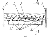
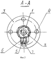
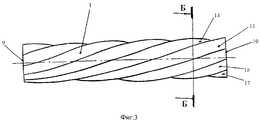
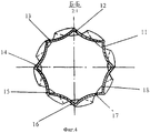
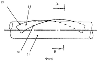
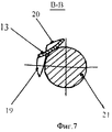
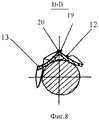
Сущность изобретения поясняется чертежами, где: на фиг.1 изображен инерционный сгуститель илистых материалов, общий вид; на фиг.2 - разрез А-А на фиг.1; на фиг.3 - корпус, изготовленный из полос прямоугольной формы свернутых в вертикальной плоскосоти в продольном направлении и изгонутых по винтовым линим в поперечном направлении с винтовыми канавками вогнутой формы, общий вид; на фиг.4 - разрез Б-Б на фиг.3; на фиг.5 - вид одной полосы после скручивания ее концов относительно горизонтальной оси О1-О; на фиг.6 - вид полосы изогнутой по винтовой линии в поперечном направлении после на оправке; на фиг.7 - разрез В-В на фиг.6; на фиг.8 - разрез В-В на фиг.6 с совмещением кромок двух полос.The invention is illustrated by drawings, where: in Fig.1 shows an inertial thickener of silty materials, General view; figure 2 is a section aa in figure 1; figure 3 - the case is made of strips of rectangular shape rolled up in a vertical plane in the longitudinal direction and bent along the helical lines in the transverse direction with helical grooves of a concave shape, General view; figure 4 is a section bB in figure 3; figure 5 is a view of one strip after twisting its ends relative to the horizontal axis O 1 -O; Fig.6 is a view of a strip curved along a helix in the transverse direction after on the mandrel; Fig.7 is a section bb in Fig.6; on Fig - section bb in Fig.6 with the alignment of the edges of the two strips.
Предлагаемый инерционный сгуститель илистых материалов (фиг.1, фиг.2) содержит многозаходный винтовой пустотелый корпус 1 с входным патрубком- фланцем 2 для крепления его в подводящему трубопроводу по которому под напором непрерывно подается илистый материал с водой, патрубок для отвода фильтрата - фланцем 3. В фланцах 2 и 3 выполнены отверстия 4 для соединительных болтов. В нижней части корпуса имеются отверстия 5 для отвода сгущенной илистой фракции в виде щелей. В той же части корпуса к нему прикреплен сборник 6 с отверстием 7. Для обеспечения дополнительного продольного перемещения илистых материалов внутри корпуса 1 и интенсификации отделения от воды сгущенных илистых фракций внутри корпуса 1 смонтировна цилиндрическая пружина 8, которая оборудована устройством для изменения шага витков цилиндрической пружины 8 путем растяжения или сжатия (не показано). Регулировка величины шага витков цилиндрической пружины 8 может производиться в процессе отделения сгущенных фракций илистых материалов.The proposed inertial thickener of silty materials (Fig. 1, Fig. 2) contains a multi-helical
Корпус 1 (фиг.3, фиг.4) с входным отверстием 9 и выходным отверстием 10, может быть изготовлен с наружными криволинейными поверхностями вогнутой или выпуклой формы относительно оси симметрии корпуса 1 с центрами кривизны снаружи или внутри корпуса 1 и выполнен из прямоугольных полос, например, 11, 12, 13, 14, 15, 16, 17, 18 скрученных по винтовой линии в продольном направлении (фиг.5) и изогнутых в поперечном направлении (фиг.6, фиг.7). Каждая из полос скручена в продольном направлении относительно собственной оси симметрии О1-О2, например полоса 13 на фиг.5 с продольными боковыми кромками 19 и 20, у которой зафиксирован в горячем или холодном состоянии один из концов и повернут другой конец полосы в заданном направлении. Скрученную таким образом полосу размещают на цилиндрическую оправку 21, как, например, на фиг.6 полосу 13, и изгибают так, чтобы кромки 19 и 20 полосы 13 разместились бы в поперечном направлении по винтовым линиям. При этом полоса 13 деформируется и ее либо снимают с оправки, либо фиксируют на ней в деформированном положении. Аналогичным образом обрабатывают остальные полосы 11, 12, 14, 15, 16, 17, 18 Далее деформированные таким образом полосы размещают на оправке 21, например как на фиг.8 полосы 13 и 12 совмещают продольные кромки, например кромку 19 полосы 12 с продольной кромкой 20 полосы 13 и соединяют известными способами, например сваркой.The housing 1 (Fig. 3, Fig. 4) with an inlet 9 and an
Инерционный сгуститель илистых фракций работает следующим образом.Inertial thickener silt fractions works as follows.
Содержащие частицы илистых материалов потоки воды попадают в корпус 1 инерционного сгустителя и вовлекается в винтообразное движение. Под действием центробежных сил частиц илистых фракций достигают криволинейных стенок и винтовых канавок корпуса 1 и выводятся чрез щели 5 в сборник 6, а затем через отверстие 7 выводится за пределы инерционного сгустителя. Процесс отделения частиц ила от воды интенсифицируется еще и витками смонтированной неподвижно внутри корпуса 1 пружины 8, витки которых изменяют направление движение частиц ила, направляя их в радиальном направлении.The streams of water containing particles of silty materials fall into the
Технике-экономические преимущества возникают за счет расширения диапазона изменений результирующих векторов перемещений частиц ила, повышение интенсивности их периориентации, повышения интенсивности отделения частиц ила от воды, расширения технологических возможностей.Techno-economic advantages arise due to the expansion of the range of changes in the resulting vectors of movement of the sludge particles, an increase in the intensity of their periorientation, an increase in the intensity of separation of the sludge particles from water, and the expansion of technological capabilities.
Claims (1)
Priority Applications (1)
| Application Number | Priority Date | Filing Date | Title |
|---|---|---|---|
| RU2012103110/05A RU2496551C2 (en) | 2012-01-30 | 2012-01-30 | Inertial thickener of sludgy materials |
Applications Claiming Priority (1)
| Application Number | Priority Date | Filing Date | Title |
|---|---|---|---|
| RU2012103110/05A RU2496551C2 (en) | 2012-01-30 | 2012-01-30 | Inertial thickener of sludgy materials |
Publications (2)
| Publication Number | Publication Date |
|---|---|
| RU2012103110A RU2012103110A (en) | 2013-08-10 |
| RU2496551C2 true RU2496551C2 (en) | 2013-10-27 |
Family
ID=49159125
Family Applications (1)
| Application Number | Title | Priority Date | Filing Date |
|---|---|---|---|
| RU2012103110/05A RU2496551C2 (en) | 2012-01-30 | 2012-01-30 | Inertial thickener of sludgy materials |
Country Status (1)
| Country | Link |
|---|---|
| RU (1) | RU2496551C2 (en) |
Cited By (4)
| Publication number | Priority date | Publication date | Assignee | Title |
|---|---|---|---|---|
| RU2548099C1 (en) * | 2014-03-06 | 2015-04-10 | Федеральное государственное бюджетное образовательное учреждение высшего профессионального образования "Кубанский государственный аграрный университет" | Unit for extraction of liquid fraction from materials |
| RU2548100C1 (en) * | 2014-02-25 | 2015-04-10 | Федеральное государственное бюджетное образовательное учреждение высшего профессионального образования "Кубанский государственный аграрный университет" | Device for separation of liquid fraction from materials |
| RU2549408C1 (en) * | 2014-02-25 | 2015-04-27 | Федеральное государственное бюджетное образовательное учреждение высшего профессионального образования "Кубанский государственный аграрный университет" | Machine for separation of liquid fraction from materials |
| RU2566430C1 (en) * | 2014-09-29 | 2015-10-27 | Федеральное государственное бюджетное образовательное учреждение высшего профессионального образования "Кубанский государственный аграрный университет" | Plant for separation of liquid phase from materials |
Citations (5)
| Publication number | Priority date | Publication date | Assignee | Title |
|---|---|---|---|---|
| SU1125017A1 (en) * | 1983-04-15 | 1984-11-23 | Саратовский Ордена Трудового Красного Знамени Политехнический Институт | Inertia thickener |
| US5137554A (en) * | 1991-09-09 | 1992-08-11 | Fasco Industries, Inc. | Cyclonic vacuum cleaner cone |
| RU2042386C1 (en) * | 1992-06-15 | 1995-08-27 | Акционерное общество "Новатор" | Inertia thickener |
| JPH11207111A (en) * | 1998-01-20 | 1999-08-03 | Teera Bunri:Kk | Load pressure controlled screw press type filter |
| RU2264843C1 (en) * | 2004-06-28 | 2005-11-27 | Кубанский государственный аграрный университет | Straight-flow spiral separator |
-
2012
- 2012-01-30 RU RU2012103110/05A patent/RU2496551C2/en not_active IP Right Cessation
Patent Citations (5)
| Publication number | Priority date | Publication date | Assignee | Title |
|---|---|---|---|---|
| SU1125017A1 (en) * | 1983-04-15 | 1984-11-23 | Саратовский Ордена Трудового Красного Знамени Политехнический Институт | Inertia thickener |
| US5137554A (en) * | 1991-09-09 | 1992-08-11 | Fasco Industries, Inc. | Cyclonic vacuum cleaner cone |
| RU2042386C1 (en) * | 1992-06-15 | 1995-08-27 | Акционерное общество "Новатор" | Inertia thickener |
| JPH11207111A (en) * | 1998-01-20 | 1999-08-03 | Teera Bunri:Kk | Load pressure controlled screw press type filter |
| RU2264843C1 (en) * | 2004-06-28 | 2005-11-27 | Кубанский государственный аграрный университет | Straight-flow spiral separator |
Cited By (4)
| Publication number | Priority date | Publication date | Assignee | Title |
|---|---|---|---|---|
| RU2548100C1 (en) * | 2014-02-25 | 2015-04-10 | Федеральное государственное бюджетное образовательное учреждение высшего профессионального образования "Кубанский государственный аграрный университет" | Device for separation of liquid fraction from materials |
| RU2549408C1 (en) * | 2014-02-25 | 2015-04-27 | Федеральное государственное бюджетное образовательное учреждение высшего профессионального образования "Кубанский государственный аграрный университет" | Machine for separation of liquid fraction from materials |
| RU2548099C1 (en) * | 2014-03-06 | 2015-04-10 | Федеральное государственное бюджетное образовательное учреждение высшего профессионального образования "Кубанский государственный аграрный университет" | Unit for extraction of liquid fraction from materials |
| RU2566430C1 (en) * | 2014-09-29 | 2015-10-27 | Федеральное государственное бюджетное образовательное учреждение высшего профессионального образования "Кубанский государственный аграрный университет" | Plant for separation of liquid phase from materials |
Also Published As
| Publication number | Publication date |
|---|---|
| RU2012103110A (en) | 2013-08-10 |
Similar Documents
| Publication | Publication Date | Title |
|---|---|---|
| RU2375099C1 (en) | Plant for separation of liquid phase from materials | |
| CN101244349A (en) | A screw press type filter for wastewater treatment | |
| RU2017122415A (en) | DRIVING HYDROCYCLONE | |
| RU2264843C1 (en) | Straight-flow spiral separator | |
| CA2614490A1 (en) | Oil sand processing apparatus | |
| RU174445U1 (en) | CENTRIFUGAL SEPARATION ELEMENT | |
| RU2469768C1 (en) | Device for separation of liquid phase from materials | |
| RU2443458C2 (en) | Swirler with hydraulic amplification | |
| RU2549408C1 (en) | Machine for separation of liquid fraction from materials | |
| RU2323030C1 (en) | Device for extracting liquid phase from materials | |
| RU2546200C1 (en) | Machine for dehydration of manure | |
| RU2521027C1 (en) | Device for separating disperse particles from gas | |
| RU2548099C1 (en) | Unit for extraction of liquid fraction from materials | |
| RU2513203C1 (en) | Disperse particles and gas separator | |
| RU2508152C1 (en) | Flow-through separator for separation of dispersed particles from gas | |
| RU141348U1 (en) | SEPARATOR FOR SEPARATION OF DISPERSED PARTICLES FROM GAS | |
| RU2506982C1 (en) | Flow-through separator for separation of dispersed particles from gas | |
| RU2506983C1 (en) | Flow-through separator | |
| RU2548100C1 (en) | Device for separation of liquid fraction from materials | |
| RU2690822C1 (en) | Apparatus for separating liquid fraction from materials | |
| RU2726053C1 (en) | Cement calcining furnace | |
| RU2506981C1 (en) | Flow-through separator for separation of dispersed particles from gas | |
| RU75328U1 (en) | SCREW CENTRIFUGE | |
| RU2457014C2 (en) | Device to change direction of fluid and gas flows | |
| RU2579221C1 (en) | Device for separation of seeds |
Legal Events
| Date | Code | Title | Description |
|---|---|---|---|
| MM4A | The patent is invalid due to non-payment of fees |
Effective date: 20140131 |