RU2499103C1 - Method for manufacturing of cast in place and precast node of pillar connection with crossbar - Google Patents
Method for manufacturing of cast in place and precast node of pillar connection with crossbar Download PDFInfo
- Publication number
- RU2499103C1 RU2499103C1 RU2012118491/03A RU2012118491A RU2499103C1 RU 2499103 C1 RU2499103 C1 RU 2499103C1 RU 2012118491/03 A RU2012118491/03 A RU 2012118491/03A RU 2012118491 A RU2012118491 A RU 2012118491A RU 2499103 C1 RU2499103 C1 RU 2499103C1
- Authority
- RU
- Russia
- Prior art keywords
- crossbar
- column
- cable
- loops
- connecting elements
- Prior art date
Links
- 238000004519 manufacturing process Methods 0.000 title claims description 10
- 238000000034 method Methods 0.000 title description 7
- 239000004567 concrete Substances 0.000 claims abstract description 16
- 230000002787 reinforcement Effects 0.000 claims abstract description 13
- 229910000831 Steel Inorganic materials 0.000 claims abstract description 9
- 239000010959 steel Substances 0.000 claims abstract description 9
- 230000008878 coupling Effects 0.000 claims abstract description 8
- 238000010168 coupling process Methods 0.000 claims abstract description 8
- 238000005859 coupling reaction Methods 0.000 claims abstract description 8
- 238000009415 formwork Methods 0.000 claims abstract description 8
- 230000003014 reinforcing effect Effects 0.000 claims description 10
- 238000009412 basement excavation Methods 0.000 claims description 5
- 238000005096 rolling process Methods 0.000 claims description 3
- 238000010276 construction Methods 0.000 abstract description 5
- 230000000694 effects Effects 0.000 abstract 1
- 238000000605 extraction Methods 0.000 abstract 1
- 239000000126 substance Substances 0.000 abstract 1
- 239000011150 reinforced concrete Substances 0.000 description 2
- 229910001294 Reinforcing steel Inorganic materials 0.000 description 1
- 238000004458 analytical method Methods 0.000 description 1
- 238000004873 anchoring Methods 0.000 description 1
- 230000001364 causal effect Effects 0.000 description 1
- 150000001875 compounds Chemical class 0.000 description 1
- 238000005516 engineering process Methods 0.000 description 1
- 238000009434 installation Methods 0.000 description 1
- 239000000463 material Substances 0.000 description 1
- 239000002184 metal Substances 0.000 description 1
- 230000003534 oscillatory effect Effects 0.000 description 1
Images



Landscapes
- Reinforcement Elements For Buildings (AREA)
Abstract
Description
Изобретение относится к области строительства, а именно к строительству жилых общественно-гражданского назначения зданий и может быть использовано в соединениях железобетонных ригелей и колонн.The invention relates to the field of construction, namely the construction of residential civil buildings and can be used in compounds of reinforced concrete crossbars and columns.
Известен способ изготовления сборно-монолитного узла соединения колонны с ригелем заключающийся в том, что каждый ригель бетонируют с опорными консолями, а в колонне выполняют выемку, куда помещают соединительные элементы ригеля, выполненные в виде стального троса запрессованными на его концах обжимными муфтами и устанавливают дополнительные арматурные стержни, сопряженные с соединительными элементами (патент России RU №2072408, МПК Е04В 1/38, опубликовано: 20.03.1998 г.).A known method of manufacturing a prefabricated-monolithic node connecting the column with the crossbar is that each crossbar is concreted with supporting consoles, and a recess is made in the column, where the connecting elements of the crossbar are made, made in the form of a steel cable, crimped couplings pressed into its ends and install additional reinforcing bars rods coupled with connecting elements (Russian patent RU No. 2072408, IPC Е04В 1/38, published: 03/20/1998).
Данное техническое решение является наиболее близким к изобретению, поэтому принято за прототип.This technical solution is the closest to the invention, therefore, taken as a prototype.
Недостатками прототипа являются трудоемкость сборки, ограниченные эксплуатационные возможности из-за сборки элементов узла на строительной площадке, невысокая надежность из-за отсутствия металлических консолей и высокой жесткости закрученных тросов, исключающих компенсацию колебательных процессов в соединении.The disadvantages of the prototype are the complexity of the Assembly, limited operational capabilities due to the assembly of the components at the construction site, low reliability due to the lack of metal consoles and high rigidity of the twisted cables, eliminating the compensation of oscillatory processes in the connection.
Технический результат от использования заявленного технического решения заключается в снижении трудоемкости сборки за счет использования тросов в виде гибких петель, повышении эксплуатационных возможностей благодаря сборки в заводских условиях ригеля с консолями и с выступающими за пределы монтажного габарита петлевыми соединительными элементами, повышение надежности за счет получения упруго податливого узла соединения.The technical result from the use of the claimed technical solution is to reduce the complexity of the assembly due to the use of cables in the form of flexible loops, increase operational capabilities due to the assembly in the factory of the bolt with consoles and loop connecting elements protruding beyond the mounting dimension, increasing reliability by obtaining an elastic flexible connection node.
Ниже приведены общие и частные существенные признаки, характеризующие причинно-следственную связь изобретения с указанным техническим результатом.The following are general and particular significant features characterizing the causal relationship of the invention with the specified technical result.
Способ изготовления сборно-монолитного узла соединения колонны с ригелем, заключающийся в том, что каждый ригель бетонируют с опорными консолями, а в колонне выполняют выемку, куда помещают соединительные элементы ригеля, выполненные в виде стального троса запрессованными на его концах обжимными муфтами и устанавливают дополнительные арматурные стержни, сопряженные с соединительными элементами. Указанную выемку бетона выполняют на уровне примыкания ригеля к колонне до оголения рабочей арматуры колонны, причем высота выемки превышает высоту ригеля, который имеет прямоугольную форму и полки для опирания плит перекрытия. Ригель предварительно изготовляют в процессе заводского производства в виде единого элемента, включающего в себя, по меньшей мере, две указанных опорных консоли из стального прокатного профиля с выпуском за пределы торца ригеля, и по меньшей мере, два указанных тросовых соединительных элемента на торце ригеля, каждый из которых предварительно складывают пополам до образования выступающей по меньшей мере за один торец ригеля петли. Все указанные петли тросов, выступающие за пределы одного торца ригеля до замоноличивания в тело ригеля ориентируют только в горизонтальной или только в вертикальной плоскостях, при этом концы тросовых соединительных элементов с обжимными муфтами на концах располагают параллельно оси ригеля и замоноличивают их теле ригеля. С помощью вспомогательных опорных средств устанавливают ригели в проектное положение относительно колонны, после чего в указанной выемке колонны в процессе изготовления сборно-монолитного узла соединения подгибают петли тросов и заводят их между арматурой колонны, Затем расправляют в проектное положение, причем внутри указанных петель тросов размещают, по меньшей мере, четыре упомянутых дополнительных арматурных стержня, разнесенных к внутренней поверхности петель тросов. После этого устанавливают опалубку и узел соединения в объеме выемки в колонне заливают бетоном, который объединяет в монолитный узел колонну, по меньшей мере, один ригель с консолями, тросовыми соединительными элементами, дополнительными арматурными стержнями и рабочей арматурой колонны. После затвердевания бетона вспомогательные опорные средства ригеля и опалубку удаляют.A method of manufacturing a prefabricated-monolithic unit for connecting the column to the crossbar, namely, that each crossbar is concreted with supporting consoles, and a recess is made in the column, where the connecting elements of the crossbar are made, made in the form of a steel cable, crimped couplings pressed into its ends and install additional reinforcing bars rods associated with connecting elements. The specified excavation of concrete is performed at the level of abutment of the crossbar to the column to expose the working reinforcement of the column, and the height of the excavation exceeds the height of the crossbar, which has a rectangular shape and shelves for supporting floor slabs. The crossbar is prefabricated in the factory production process in the form of a single element, which includes at least two of these supporting consoles of steel rolling profile with the release beyond the end of the crossbar, and at least two of these cable connecting elements on the end of the crossbar, each of which they are preliminarily folded in half until a loop protruding at least one end of the crossbar is formed. All these cable loops protruding beyond one end of the crossbar until monolithic in the crossbar body are oriented only in the horizontal or only vertical planes, while the ends of the cable connecting elements with crimp couplings at the ends are parallel to the crossbar axis and monolize their crossbar body. Using auxiliary support means, the crossbars are installed in the design position relative to the column, after which, in the process of manufacturing the prefabricated monolithic connection unit, the cable loops are bent and wound between the column fittings, then straightened to the design position, and placed inside the indicated cable loops, at least four of the mentioned additional reinforcing bars spaced to the inner surface of the cable loops. After that, the formwork is installed and the connection unit in the recess volume in the column is poured with concrete, which combines at least one crossbar with consoles, cable connecting elements, additional reinforcing bars and working reinforcement of the column into a monolithic node. After the concrete has hardened, the auxiliary support means of the crossbar and the formwork are removed.
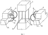
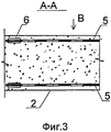
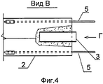
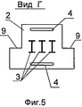
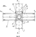
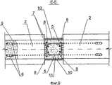
Изобретение иллюстрируется чертежами, где: на фиг.1 представлены в изометрии элементы сборно-монолитного узла; на фиг.2 представлен сборно-монолитный узел, вид сбоку; на фиг.3 - вид А-А на фиг.2; на фиг.4 - вид В на фиг.3; на фиг.5 - вид Г на фиг.4; на фиг.6 - вид Б-Б на фиг.2; на фиг.7 - вид Д-Д на фиг.6; на фиг.8 - вид Е-Е на фиг.6; на фиг.9 - вид Е-Е на фиг.6, вариант.The invention is illustrated by drawings, where: in Fig. 1, isometric elements of a precast-monolithic assembly are presented; figure 2 presents the precast-monolithic node, side view; figure 3 is a view aa in figure 2; figure 4 is a view In figure 3; figure 5 is a view of figure 4; figure 6 is a view of BB in figure 2; Fig.7 is a view of DD in Fig.6; in Fig.8 is a view of EE in Fig.6; Fig.9 is a view of EE in Fig.6, a variant.
Способ изготовления сборно-монолитного узла соединения колонны 1 с ригелем 2, заключается в том, что каждый ригель 2 бетонируют с опорными консолями 3, а в колонне выполняют выемку, куда помещают соединительные элементы 4 ригеля, выполненные в виде стального троса 5 с запрессованными на его концах обжимными муфтами 6 и устанавливают дополнительные арматурные стержни 7, сопряженные с соединительными элементами 4.A method of manufacturing a prefabricated-monolithic unit for connecting the
Указанную выемку бетона выполняют на уровне примыкания ригеля 2 к колонне 1 до оголения рабочей арматуры 8 колонны 1, причем высота выемки превышает высоту ригеля 2, который имеет прямоугольную форму и полки 9 для опирания плит перекрытия (не показано).The specified excavation of concrete is performed at the level of abutment of the
Ригель 2 предварительно изготовляют в процессе заводского производства в виде единого элемента, включающего в себя по меньшей мере две указанных опорных консоли 3 из стального прокатного профиля с выпуском за пределы торца ригеля 2, и по меньшей мере, два указанных тросовых соединительных элемента 5 на торце ригеля 2, каждый из которых предварительно складывают пополам до образования выступающей, по меньшей мере, за один торец ригеля 2 петли (фиг.1).The
Все указанные петли тросов 5, выступающие за пределы одного торца ригеля 2 до замоноличивания в тело ригеля 2 ориентируют только в горизонтальной или только в вертикальной плоскостях, при этом концы тросовых соединительных элементов 4 с обжимными муфтами 6 на концах располагают параллельно оси ригеля 2 и замоноличивают их в теле ригеля 2.All of these loops of
Затем с помощью вспомогательных опорных средств (не показано) устанавливают ригели 2 в проектное положение относительно колонны 1, после чего в указанной выемке колонны 1 в процессе изготовления сборно-монолитного узла соединения подгибают петли тросов 5 и заводят их между рабочей арматурой колонны 8, а затем расправляют в проектное положение.Then, using auxiliary support means (not shown), the
Внутри указанных петель тросов 5 размещают, по меньшей мере, четыре упомянутых дополнительных арматурных стержня 7, разнесенных к внутренней поверхности петель тросов 5, после этого устанавливают опалубку 10 и узел соединения в объеме 11 выемки в колонне 1 заливают бетоном, который объединяет в монолитный узел колонну 1 по меньшей мере один ригель 2 с консолями 3, тросовыми соединительными элементами 5, дополнительными арматурными стержнями 7 и рабочей арматурой колонны 8, затем после затвердевания бетона вспомогательные опорные средства ригеля 2 и опалубку 10 удаляют.At least four of the
Сравнение заявленного технического решения с уровнем техники известным из научно-технической и патентной документации на дату приоритета в основной и смежной рубриках не выявило средство, которому присущи признаки, идентичные всем признакам, содержащимся в предложенной заявителем формуле изобретения, включая характеристику назначения. Т.е. совокупность существенных признаков заявленного решения ранее не была известна и не тождественна каким-либо известным техническим решениям, следовательно, оно соответствует условию патентоспособности "новизна".Comparison of the claimed technical solution with the prior art known from the scientific, technical and patent documentation as of the priority date in the main and related sections did not reveal a tool that has features identical to all the features contained in the claims proposed by the applicant, including the purpose of the application. Those. the set of essential features of the claimed solution was not previously known and is not identical to any known technical solutions, therefore, it meets the condition of patentability "novelty".
Данное техническое решение промышленно применимо, поскольку в описании к заявке и названии изобретения указано его назначение, оно может быть осуществлено промышленным способом и использовано для соединения железобетонных ригелей и колонн.This technical solution is industrially applicable, since its description is indicated in the description of the application and the title of the invention, it can be carried out industrially and used to connect reinforced concrete crossbars and columns.
Техническое решение работоспособно, осуществимо и воспроизводимо, а отличительные признаки устройства позволяют получить заданный технический результат, т.е. являются существенными.The technical solution is workable, feasible and reproducible, and the distinguishing features of the device allow to obtain the desired technical result, i.e. are significant.
Техническое решение в том виде, как оно охарактеризовано в каждом из пунктов формулы, может быть осуществлено с помощью средств и методов, описанных в прототипе, ставшим общедоступным до даты приоритета изобретения. Следовательно, заявленное техническое решение соответствует условию патентоспособности "промышленная применимость".The technical solution, as described in each of the claims, can be implemented using the tools and methods described in the prototype, which became public until the priority date of the invention. Therefore, the claimed technical solution meets the condition of patentability "industrial applicability".
Анализ известных технических решений в области изобретения показал, что предложенный способ не следует для специалиста явным образом из уровня техники, поскольку не выявлены решения, имеющие признаки, совпадающие с отличительными признаками изобретения и не подтверждена известность влияния отличительных признаков на указанный в материалах заявки технический результат. Т.е. заявленное изобретение имеет признаки, которые отсутствуют в известных технических решениях, а использование этих признаков в заявленной совокупности существенных признаков дает возможность получить новый технический результат - в снижение трудоемкости сборки, повышение эксплуатационных возможностей и надежности.Analysis of known technical solutions in the field of the invention showed that the proposed method does not follow explicitly from the prior art for a specialist, since solutions having features matching the distinguishing features of the invention have not been identified and the influence of the distinctive features on the technical result indicated in the application materials has not been confirmed. Those. the claimed invention has features that are absent in the known technical solutions, and the use of these features in the claimed combination of essential features makes it possible to obtain a new technical result - to reduce the complexity of the assembly, increase operational capabilities and reliability.
Следовательно, предложенное техническое решение может быть получено только путем творческого подхода и неочевидно для среднего специалиста в этой области, т.е. соответствует условию патентоспособности изобретения «изобретательский уровень» и, следовательно, является новым и имеет изобретательский уровень.Therefore, the proposed technical solution can only be obtained through a creative approach and is not obvious to the average person skilled in this field, i.e. meets the condition of patentability of the invention "inventive step" and, therefore, is new and has an inventive step.
Изобретение реализуется следующим образом.The invention is implemented as follows.
В заводских условиях изготовляют ригель 2 совместно с закладными консолями 3, которые передают поперечные усилия от ригеля 2 на колонну 1. Затем в ригель 2 замоноличивается трос 5 обжимными муфтами 6, который предварительно складывается пополам, образуя на торце ригеля 2 петлю троса 5 выступающую за его пределы. При этом петли троса 5 могут быть ориентированы в горизонтальной или вертикальной плоскостях. Тросы передают усилия, работая, как арматура в бетоне. Это фактически арматура только гибкая. Для усиления анкеровки тросовых петель 5 в бетоне предусматривается установка дополнительных арматурных стержней 7, которые примыкают к тросу со стороны внутренней части его петли.In the factory, the
Затем в колонне 1 выполняют выемку бетона до оголения рабочей арматуры 8 и с помощью вспомогательных средств (не показано) ориентируют ригели 2 относительно колонны 1 в проектное положение. При этом в процессе сборки петли тросов 5 подгибают и заводят между рабочей арматурой 8 колонны 1, а затем устанавливают опалубку 10 образуя объем 11, который заливают бетоном. Перед заливкой бетоном тросовые петли 5 расправляют в проектное положение.Then, in the
Использование изобретения позволяет снизить трудозатраты на сборку, расширить эксплуатационные возможности и повысить надежность узла соединения и самого объекта строительства.The use of the invention allows to reduce labor costs for the assembly, expand operational capabilities and increase the reliability of the connection node and the construction site itself.
Петлевые выпуски из троса 5 позволяют получить возможность смонтировать ригель 2 с выступающими за пределы монтажного габарита элементами (петлями), что значительно улучшает технологию соединения колонны 1 с ригелями 2, т.к. в случае применения петель из обычной арматурной стали вставить ригель 2 в пространство в колонне 1 не представляется возможным.Loop outlets from
Claims (1)
Priority Applications (1)
| Application Number | Priority Date | Filing Date | Title |
|---|---|---|---|
| RU2012118491/03A RU2499103C1 (en) | 2012-05-05 | 2012-05-05 | Method for manufacturing of cast in place and precast node of pillar connection with crossbar |
Applications Claiming Priority (1)
| Application Number | Priority Date | Filing Date | Title |
|---|---|---|---|
| RU2012118491/03A RU2499103C1 (en) | 2012-05-05 | 2012-05-05 | Method for manufacturing of cast in place and precast node of pillar connection with crossbar |
Publications (1)
| Publication Number | Publication Date |
|---|---|
| RU2499103C1 true RU2499103C1 (en) | 2013-11-20 |
Family
ID=49710144
Family Applications (1)
| Application Number | Title | Priority Date | Filing Date |
|---|---|---|---|
| RU2012118491/03A RU2499103C1 (en) | 2012-05-05 | 2012-05-05 | Method for manufacturing of cast in place and precast node of pillar connection with crossbar |
Country Status (1)
| Country | Link |
|---|---|
| RU (1) | RU2499103C1 (en) |
Cited By (3)
| Publication number | Priority date | Publication date | Assignee | Title |
|---|---|---|---|---|
| CN108265828A (en) * | 2018-03-19 | 2018-07-10 | 沈阳建筑大学 | Assembly concrete-filled steel tube beam column goes along with sb. to guard him integrated system |
| CN114888951A (en) * | 2022-04-25 | 2022-08-12 | 安徽建工北城工业有限公司 | Manufacturing method for prefabricated wall panel with reserved overhanging reinforcing steel bars on die table top |
| CN115949146A (en) * | 2023-03-14 | 2023-04-11 | 中交第四航务工程勘察设计院有限公司 | Ribbed plate type connecting joint of PC column-steel beam, column-beam system and assembling method thereof |
Citations (4)
| Publication number | Priority date | Publication date | Assignee | Title |
|---|---|---|---|---|
| RU2072408C1 (en) * | 1994-12-29 | 1997-01-27 | Проектный институт "Кемеровгорпроект" | Butt joints between wall panels and column |
| DE202004002110U1 (en) * | 2004-02-11 | 2005-06-30 | Pfeifer Holding Gmbh & Co. Kg | Connecting element for connecting precast concrete elements |
| RU60099U1 (en) * | 2006-07-31 | 2007-01-10 | Сергей Анатольевич Романов | MILITARY MONOLITHIC REINFORCED CONCRETE FRAME OF MULTI-STOREY BUILDING |
| DE102008013206A1 (en) * | 2008-03-07 | 2009-09-10 | P & T Technische Mörtel GmbH & Co. KG | Precast concrete part i.e. wall element, connecting method for building, involves filling interstice with fast hardening sealing mortars compared to grout, and filling remaining gaps between connecting surfaces and interstice with grout |
-
2012
- 2012-05-05 RU RU2012118491/03A patent/RU2499103C1/en not_active IP Right Cessation
Patent Citations (4)
| Publication number | Priority date | Publication date | Assignee | Title |
|---|---|---|---|---|
| RU2072408C1 (en) * | 1994-12-29 | 1997-01-27 | Проектный институт "Кемеровгорпроект" | Butt joints between wall panels and column |
| DE202004002110U1 (en) * | 2004-02-11 | 2005-06-30 | Pfeifer Holding Gmbh & Co. Kg | Connecting element for connecting precast concrete elements |
| RU60099U1 (en) * | 2006-07-31 | 2007-01-10 | Сергей Анатольевич Романов | MILITARY MONOLITHIC REINFORCED CONCRETE FRAME OF MULTI-STOREY BUILDING |
| DE102008013206A1 (en) * | 2008-03-07 | 2009-09-10 | P & T Technische Mörtel GmbH & Co. KG | Precast concrete part i.e. wall element, connecting method for building, involves filling interstice with fast hardening sealing mortars compared to grout, and filling remaining gaps between connecting surfaces and interstice with grout |
Cited By (5)
| Publication number | Priority date | Publication date | Assignee | Title |
|---|---|---|---|---|
| CN108265828A (en) * | 2018-03-19 | 2018-07-10 | 沈阳建筑大学 | Assembly concrete-filled steel tube beam column goes along with sb. to guard him integrated system |
| CN108265828B (en) * | 2018-03-19 | 2023-10-27 | 张延年 | Prefabricated steel tube concrete beam and column enclosure integrated system |
| CN114888951A (en) * | 2022-04-25 | 2022-08-12 | 安徽建工北城工业有限公司 | Manufacturing method for prefabricated wall panel with reserved overhanging reinforcing steel bars on die table top |
| CN114888951B (en) * | 2022-04-25 | 2024-06-07 | 安徽建工北城工业有限公司 | Manufacturing method for reserving overhanging reinforcing steel bars on die surface of prefabricated wallboard |
| CN115949146A (en) * | 2023-03-14 | 2023-04-11 | 中交第四航务工程勘察设计院有限公司 | Ribbed plate type connecting joint of PC column-steel beam, column-beam system and assembling method thereof |
Similar Documents
| Publication | Publication Date | Title |
|---|---|---|
| KR101630235B1 (en) | Precast truss wall structure and construction method of underground structure using thereof | |
| KR101379305B1 (en) | Wall structure manufacturing method using precast front wall panel and precast back wall panel | |
| CN102720272B (en) | Embedded column type prefabricated part connection node and manufacturing method thereof | |
| EP2559817A2 (en) | Adjustable system for embedded union of prefabricated concrete elements for building structures, and method for performing the union of prefabricated concrete elements | |
| CN108678220B (en) | A concrete shear wall with integrated steel formwork installation | |
| KR101269639B1 (en) | The core-type sleeve of precast concrete for member of framework | |
| CN203947586U (en) | The connected node of prefabricated sandwich side fascia | |
| CN104074274A (en) | Connection joint of prefabricated sandwich side fascia | |
| KR101329443B1 (en) | Precast concrete frame and its construction method for buildings using precast concrete slab continued by post tensioning | |
| KR101216126B1 (en) | Arch structure construction method using axial and longitudinal connection rebar | |
| JP6943581B2 (en) | Wall beam joint structure | |
| WO2016020932A2 (en) | Deployable pre-fabricated reinforcement cage system | |
| RU120669U1 (en) | COMBINED MONOLITHIC NODE FOR CONNECTING THE COLUMN WITH THE CROSS | |
| JP2013209829A (en) | Construction method of wall | |
| KR100612662B1 (en) | Rebar Network Assembly Method of Reinforced Concrete Structure | |
| KR20160019286A (en) | Psc girder with end diaphragm and semi-integral abutment bridge construction method therewith | |
| RU156642U1 (en) | COLUMN ASSEMBLY ASSEMBLY | |
| RU123042U1 (en) | ELEMENT OF MONOLITHIC CONCRETE COVERING | |
| KR20130038089A (en) | Precast concrete frame for buildings using precast concrete beam continued by post tensioning | |
| KR101109244B1 (en) | Structural wall reinforced with plastic hinge part with fiber reinforced concrete | |
| KR20120049719A (en) | Slab joining method | |
| KR100203012B1 (en) | Executing method of building works used a pc slab | |
| RU2387763C1 (en) | Method for erection of monolithic walls of residential buildings, housings and structures in combined curb | |
| RU2704396C1 (en) | Hollow-core reinforced concrete slab with means of reinforcement of support zone | |
| KR101221161B1 (en) | Wall Structure having Half-slab Precast Panel and Constructing Method thereof |
Legal Events
| Date | Code | Title | Description |
|---|---|---|---|
| MM4A | The patent is invalid due to non-payment of fees |
Effective date: 20140506 |