RU2505373C2 - Method of thread cutting at billet - Google Patents
Method of thread cutting at billet Download PDFInfo
- Publication number
- RU2505373C2 RU2505373C2 RU2012103574/02A RU2012103574A RU2505373C2 RU 2505373 C2 RU2505373 C2 RU 2505373C2 RU 2012103574/02 A RU2012103574/02 A RU 2012103574/02A RU 2012103574 A RU2012103574 A RU 2012103574A RU 2505373 C2 RU2505373 C2 RU 2505373C2
- Authority
- RU
- Russia
- Prior art keywords
- thread
- cutting
- rolling
- workpiece
- head
- Prior art date
Links
- 238000005520 cutting process Methods 0.000 title claims abstract description 23
- 238000000034 method Methods 0.000 title claims description 14
- 238000005096 rolling process Methods 0.000 claims description 27
- 210000001520 comb Anatomy 0.000 claims description 12
- 239000000126 substance Substances 0.000 abstract 1
- 239000000463 material Substances 0.000 description 6
- 239000002184 metal Substances 0.000 description 6
- 230000015572 biosynthetic process Effects 0.000 description 3
- 238000003754 machining Methods 0.000 description 2
- 238000011089 mechanical engineering Methods 0.000 description 2
- 238000003801 milling Methods 0.000 description 2
- 230000006378 damage Effects 0.000 description 1
- 238000005553 drilling Methods 0.000 description 1
- 238000005516 engineering process Methods 0.000 description 1
- 238000004519 manufacturing process Methods 0.000 description 1
- 238000002360 preparation method Methods 0.000 description 1
- 230000003014 reinforcing effect Effects 0.000 description 1
Images
Landscapes
- Turning (AREA)
- Forging (AREA)
Abstract
Description
Изобретение относится к технологии машиностроения, к способам формообразования наружных резьб пластическим деформированием, в частности к получению наружных резьб комбинированной режуще-деформирующей обработкой.The invention relates to mechanical engineering technology, to methods of forming external threads by plastic deformation, in particular to the production of external threads by combined cutting-deformation processing.
Известный способ получения наружных резьб накатыванием резьбона-катными головками с осевой подачей (см. Киричек А.В., Афонин А.Н. Резьбонакатывание. Библиотека технолога. - М.: Машиностроение, 2009. - С.130) позволяет изготавливать резьбы высокого качества с высокой производительностью.A known method of producing external threads by rolling the threading-rolling heads with axial feed (see Kirichek A.V., Afonin A.N. Thread rolling. Library technologist. - M .: Mechanical Engineering, 2009. - P.130) allows to produce high-quality threads with high performance.
Недостатком данного способа является то, что он не нашел применения для получения крупных трапецеидальных резьб и резьб на заготовках из материалов с пониженной пластичностью из-за опасности разрушения материала заготовки в связи с исчерпанием запаса пластичности металла (переупрочнением).The disadvantage of this method is that it did not find application for obtaining large trapezoidal threads and threads on workpieces from materials with reduced ductility due to the risk of destruction of the workpiece material due to the exhaustion of the ductility of the metal (reinforcing).
Избежать переупрочнения можно применением комбинированной режуще-деформирующей обработки, заключающейся в накатывании резьбы по предварительно прорезанной винтовой канавке. Известен способ резьбофре-зерования с накатыванием, осуществляемый головкой, имеющей хвостовик, корпус, крышку и оси, установленные на подшипниках, при котором заготовке сообщают вращательное движение, а головке - осевую подачу, причем предварительное формирование резьбы осуществляют мелкозубыми дисковыми резьбовыми фрезами, жестко закрепленными на осях, а окончательное профилирование резьбы производят свободно вращающимися резьбонакат-ными роликами, имеющими заборную и калибрующую части (Патент РФ №2252099, МПК B21H 3/02. Способ резьбофрезерования с накатыванием. Опубликован в 2005 г.).Over-hardening can be avoided by using a combined cutting-deforming treatment, which consists in rolling threads along a previously cut helical groove. A known method of thread milling with rolling, carried out by a head having a shank, a housing, a cover and axes mounted on bearings, in which the workpiece is rotationally informed, and the head is axially fed, and the thread is preliminarily formed by fine-tooth disk threaded mills rigidly fixed to axes, and the final profiling of the thread is carried out by freely rotating thread rolling rollers having intake and gauge parts (RF Patent No. 2252099, IPC
Недостатком данного способа является то, что накатывание резьбы по предварительно прорезанной винтовой канавке отличается более низкой, по сравнению с накатыванием по целому, глубиной упрочненного слоя.The disadvantage of this method is that the rolling of the thread on a previously cut helical groove is lower in comparison with the rolling on the whole, the depth of the hardened layer.
Известна режуще-резьбонакатная головка, при обработке которой заготовке сообщается вращательное движение, а головке осевое движение подачи (А.с. СССР 1315180. Кл. B35G 5/00. Режуще-резьбонакатная головка. Опубликовано в 1987 г.). Головка обеспечивает расширение технологических возможностей накатывания за счет формирования заходного конуса на заготовках.Known cutting-thread-rolling head, during the processing of which the workpiece is given a rotational movement, and the head axial movement of the feed (AS USSR 1315180. Cl. B35G 5/00. Cutting-thread-rolling head. Published in 1987). The head provides the expansion of technological capabilities of rolling due to the formation of a lead-in cone on the workpieces.
Недостатком данной головки является то, что она не обеспечивает возможности срезания переупрочненного металла при получении крупных трапецеидальных резьб и резьб на заготовках из материалов с пониженной пластичностью.The disadvantage of this head is that it does not provide the ability to cut re-hardened metal upon receipt of large trapezoidal threads and threads on workpieces from materials with reduced ductility.
Техническим результатом изобретения является повышение глубины упрочнения при режуще-деформирующей обработке крупных трапецеидальных резьб и резьб на заготовках из материалов с пониженной пластичностью.The technical result of the invention is to increase the depth of hardening during cutting-deformation processing of large trapezoidal threads and threads on workpieces from materials with reduced ductility.
Технический результат изобретения достигается тем, используют резьбонакатную головку, содержащую резьбонакатные ролики, между которыми установлены режущие гребенки с зубьями с режущими кромками, расположенными напротив выступов накатываемой роликами на заготовке резьбы, при этом ширина вершины зубьев режущих гребенок равна ширине вершины выступов накатываемой роликами на заготовке резьбы, а зубья режущих гребенок расположены таким образом, что их режущие кромки находятся на расстоянии a i - 0,94H i от впадины накатываемой роликами на заготовке резьбы, где H i - высота выступа резьбы, формируемого i витком заборной части ролика.The technical result of the invention is achieved by using a thread rolling head containing thread rolling rollers, between which cutting combs are installed with teeth with cutting edges located opposite the protrusions of the rolling rollers on the thread workpiece, while the width of the teeth of the cutting combs is equal to the width of the tops of the protrusions of the rolling combs on the thread workpiece and the teeth of the cutting combs are located in such a way that their cutting edges are at a distance a i - 0.94 H i from the cavity rolled by the rollers thread preparation, where H i is the height of the thread protrusion formed by the i turn of the intake part of the roller.
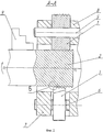
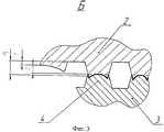
На фиг.1 изображена головка, реализующая предлагаемый способ, вид спереди; на фиг.2 - сечение A-A фиг.1; на фиг.3 - вид Б фиг.2.Figure 1 shows the head that implements the proposed method, front view; figure 2 is a section A-A of figure 1; figure 3 is a view B of figure 2.
Предлагаемый способ накатывания наружной резьбы на заготовке предназначен для получения крупных наружных трапецеидальных резьб и резьб на заготовках из материалов с пониженной пластичностью. Способ осуществляется специальной головкой, при этом заготовке сообщают вращательное движение, а головке - осевую подачу (при обработке на токарном станке). При обработке на сверлильном станке заготовка может быть неподвижной, а главное вращательное движение и поступательное движение осевой подачи могут сообщаться головке.The proposed method of rolling external threads on a workpiece is designed to produce large external trapezoidal threads and threads on workpieces from materials with reduced ductility. The method is carried out by a special head, while the workpiece is given a rotational movement, and the head is axially fed (when machining on a lathe). When machining on a drilling machine, the workpiece may be stationary, and the main rotational motion and translational movement of the axial feed can be communicated to the head.
Головка, реализующая предлагаемый способ, содержит три или более резьбонакатных ролика 1, имеющих коническую заборную и цилиндрическую калибрующую части с кольцевыми выступами, имеющими форму профиля, соответствующий профилю впадины накатываемой резьбы. Оси вращения роликов 1 находятся под углом к оси вращения заготовки 2, равным углу подъема накатываемой резьбы. Между роликами по окружности напротив заборной части установлены режущие гребенки 3. Ширина вершины зубьев 4 режущих гребенок 3 равна ширине вершины выступов накатываемой роликами 1 на заготовке 2 резьбы. При этом зубья 4 гребенок 3 расположены таким образом, что их режущие кромки находятся на расстоянии a i - 0,94H i от впадины накатываемой роликами на заготовке резьбы, где H i - высота выступа резьбы, формируемого i витком заборной части ролика.The head that implements the proposed method contains three or more
Оси 5 и 6 роликов 1 и гребенок 3 соответственно закреплены в передней 7 и задней 8 крышках головки.The
Обрабатываемой заготовке 2, закрепленной в патроне 9, который расположен на шпинделе станка (на рисунке не показан), сообщается вращательное движение V З . При подводе головки к заготовке ей сообщается продольная подача S пр, равная шагу накатываемой резьбы на оборот заготовки. При перемещении головки относительно заготовки в осевом направлении происходит внедрение в заготовку 2 витков заборной части роликов 1. При этом металл из впадин накатываемой резьбы выдавливается в выступ. Края выступа приподняты относительно его середины из-за образования перед роликом волны металла 7 высотой h B=0,06…0,10H i. Зубья режущей гребенки 3, следующие за роликом 1, срезают волну 6 на вершине выступов накатываемой роликами на заготовке 2 резьбы, придавая ей плоскую в осевом сечении форму. Таким образом, они удаляют слой металла, подвергшийся переупрочнению. Однако, общий объем срезанного металла невелик, в связи с чем глубина упрочненного слоя практически не отличается от глубины упрочненного слоя при накатывании резьбы по целому.
После окончания формирования резьбы обрабатываемой заготовке 2 сообщается ускоренное вращение в обратную сторону, и она выкручивается из головки. Режущие гребенки 3 при этом не контактируют с накатанной резьбой. Для повышения производительности за счет ускоренного вывода заготовки головка может быть оснащена механизмом раскрытия (на рисунке не показан), отводящим от центра заготовки резьбонакатные ролики 1 и режущие гребенки 3 после завершения обработки на расстояние большее, чем высота профиля накатанной на заготовке 2 резьбы H max.After completion of the thread formation, the
Предлагаемый способ комбинированного режуще-деформирующего накатывания наружных резьб специальной головкой с осевой подачей позволяет получать крупные трапецеидальные резьбы и резьбы на заготовках из материалов пониженной пластичностью с высокой производительностью и качеством, при этом головка имеет относительно простую конструкцию. Способ обеспечивает степень и глубину упрочнения, практически не отличающуюся от степени и глубины упрочнения при накатывании резьбы по целому и на 20…30% больше, чем при известных способах режуще-деформирующей обработки резьб.The proposed method of combined cutting-deforming rolling of external threads with a special head with axial feed makes it possible to obtain large trapezoidal threads and threads on workpieces made of materials with reduced ductility with high productivity and quality, while the head has a relatively simple design. The method provides a degree and depth of hardening that does not practically differ from the degree and depth of hardening when rolling the thread in whole and by 20 ... 30% more than with the known methods of cutting-deformation processing of threads.
Claims (1)
Priority Applications (1)
| Application Number | Priority Date | Filing Date | Title |
|---|---|---|---|
| RU2012103574/02A RU2505373C2 (en) | 2012-02-02 | 2012-02-02 | Method of thread cutting at billet |
Applications Claiming Priority (1)
| Application Number | Priority Date | Filing Date | Title |
|---|---|---|---|
| RU2012103574/02A RU2505373C2 (en) | 2012-02-02 | 2012-02-02 | Method of thread cutting at billet |
Publications (2)
| Publication Number | Publication Date |
|---|---|
| RU2012103574A RU2012103574A (en) | 2013-08-10 |
| RU2505373C2 true RU2505373C2 (en) | 2014-01-27 |
Family
ID=49159202
Family Applications (1)
| Application Number | Title | Priority Date | Filing Date |
|---|---|---|---|
| RU2012103574/02A RU2505373C2 (en) | 2012-02-02 | 2012-02-02 | Method of thread cutting at billet |
Country Status (1)
| Country | Link |
|---|---|
| RU (1) | RU2505373C2 (en) |
Citations (4)
| Publication number | Priority date | Publication date | Assignee | Title |
|---|---|---|---|---|
| SU489571A2 (en) * | 1974-06-11 | 1975-10-30 | Die for male threading | |
| SU1315180A1 (en) * | 1986-03-19 | 1987-06-07 | Московский станкоинструментальный институт | Thread cutting and rolling head |
| SU1500425A1 (en) * | 1987-11-10 | 1989-08-15 | Центральное Проектно-Конструкторское И Технологическое Бюро Главсантехпрома | Thread-cutting head |
| JPH094622A (en) * | 1995-06-16 | 1997-01-07 | Honda Motor Co Ltd | Grooved bolt and method of manufacturing the same |
-
2012
- 2012-02-02 RU RU2012103574/02A patent/RU2505373C2/en not_active IP Right Cessation
Patent Citations (4)
| Publication number | Priority date | Publication date | Assignee | Title |
|---|---|---|---|---|
| SU489571A2 (en) * | 1974-06-11 | 1975-10-30 | Die for male threading | |
| SU1315180A1 (en) * | 1986-03-19 | 1987-06-07 | Московский станкоинструментальный институт | Thread cutting and rolling head |
| SU1500425A1 (en) * | 1987-11-10 | 1989-08-15 | Центральное Проектно-Конструкторское И Технологическое Бюро Главсантехпрома | Thread-cutting head |
| JPH094622A (en) * | 1995-06-16 | 1997-01-07 | Honda Motor Co Ltd | Grooved bolt and method of manufacturing the same |
Also Published As
| Publication number | Publication date |
|---|---|
| RU2012103574A (en) | 2013-08-10 |
Similar Documents
| Publication | Publication Date | Title |
|---|---|---|
| US4278374A (en) | Apparatus for screw-threading | |
| EP2570230B1 (en) | Device and method for finishing workpieces | |
| CN106687241B (en) | For the method to the device and operation described device that carry out gear hobbing processing with tooth workpiece | |
| EP2570229B1 (en) | Device and method for finishing workpieces | |
| WO2013038024A1 (en) | Method and device for finishing workpieces | |
| CN103658698B (en) | Cylinder rapid shaping cutter | |
| CN108136519A (en) | Finish-milling tool, particularly slotting cutter | |
| CN104114309A (en) | Tool for the chipless production or finishing of a thread on a workpiece, in particular cold-forming tap or thread-forming tap | |
| DE4315503B4 (en) | Method for producing a hollow workpiece, which is profiled at least inside straight or obliquely to the workpiece axis | |
| RU2505373C2 (en) | Method of thread cutting at billet | |
| JP2016010847A (en) | Composite gear cutting tool | |
| JP2016087695A (en) | Screw grinding machine | |
| CN110621429B (en) | Method for machining teeth and gear cutting machines designed therefor, and related computer program products | |
| RU2312752C1 (en) | Needle milling cutter tool for strengthening | |
| CN206083456U (en) | Many screw threads inside spin hard alloy bar's extrusion device | |
| US3260100A (en) | Apparatus for simultaneously imparting an alternate series of thread forms on a workpiece | |
| KR101819587B1 (en) | Worm shaft manufacturing type Precursor dies | |
| CN103260806A (en) | Method for producing a thread in a workpiece | |
| US2749808A (en) | Thread chasing | |
| JPH09133195A (en) | Ball screw and manufacture thereof | |
| KR102202386B1 (en) | Cutting tool for bevel gear and processing method of bevel gear using cutting tool | |
| CN107538087B (en) | Method for dressing a multi-threaded grinding worm by means of dressing rollers | |
| CN110076396A (en) | A kind of processing technology of steep-lead thread | |
| JP5311901B2 (en) | Screw rolling dies | |
| JP2020116688A (en) | Manufacturing method of male screw member |
Legal Events
| Date | Code | Title | Description |
|---|---|---|---|
| MM4A | The patent is invalid due to non-payment of fees |
Effective date: 20140203 |