RU2511706C2 - Method of evaluating spectacle lenses, method of designing spectacle lenses, method of manufacturing spectacle lenses, system for manufacturing spectacle lenses and spectacle lens - Google Patents
Method of evaluating spectacle lenses, method of designing spectacle lenses, method of manufacturing spectacle lenses, system for manufacturing spectacle lenses and spectacle lens Download PDFInfo
- Publication number
- RU2511706C2 RU2511706C2 RU2011136700/28A RU2011136700A RU2511706C2 RU 2511706 C2 RU2511706 C2 RU 2511706C2 RU 2011136700/28 A RU2011136700/28 A RU 2011136700/28A RU 2011136700 A RU2011136700 A RU 2011136700A RU 2511706 C2 RU2511706 C2 RU 2511706C2
- Authority
- RU
- Russia
- Prior art keywords
- convergence
- relative
- fusion
- value
- accommodation
- Prior art date
Links
Images











Classifications
-
- G—PHYSICS
- G01—MEASURING; TESTING
- G01M—TESTING STATIC OR DYNAMIC BALANCE OF MACHINES OR STRUCTURES; TESTING OF STRUCTURES OR APPARATUS, NOT OTHERWISE PROVIDED FOR
- G01M11/00—Testing of optical apparatus; Testing structures by optical methods not otherwise provided for
- G01M11/02—Testing optical properties
- G01M11/0242—Testing optical properties by measuring geometrical properties or aberrations
- G01M11/0257—Testing optical properties by measuring geometrical properties or aberrations by analyzing the image formed by the object to be tested
-
- G—PHYSICS
- G02—OPTICS
- G02C—SPECTACLES; SUNGLASSES OR GOGGLES INSOFAR AS THEY HAVE THE SAME FEATURES AS SPECTACLES; CONTACT LENSES
- G02C7/00—Optical parts
- G02C7/02—Lenses; Lens systems ; Methods of designing lenses
- G02C7/024—Methods of designing ophthalmic lenses
- G02C7/027—Methods of designing ophthalmic lenses considering wearer's parameters
-
- G—PHYSICS
- G02—OPTICS
- G02C—SPECTACLES; SUNGLASSES OR GOGGLES INSOFAR AS THEY HAVE THE SAME FEATURES AS SPECTACLES; CONTACT LENSES
- G02C7/00—Optical parts
- G02C7/02—Lenses; Lens systems ; Methods of designing lenses
- G02C7/06—Lenses; Lens systems ; Methods of designing lenses bifocal; multifocal ; progressive
- G02C7/061—Spectacle lenses with progressively varying focal power
-
- G—PHYSICS
- G02—OPTICS
- G02C—SPECTACLES; SUNGLASSES OR GOGGLES INSOFAR AS THEY HAVE THE SAME FEATURES AS SPECTACLES; CONTACT LENSES
- G02C2202/00—Generic optical aspects applicable to one or more of the subgroups of G02C7/00
- G02C2202/06—Special ophthalmologic or optometric aspects
Landscapes
- Physics & Mathematics (AREA)
- Health & Medical Sciences (AREA)
- Ophthalmology & Optometry (AREA)
- General Physics & Mathematics (AREA)
- General Health & Medical Sciences (AREA)
- Optics & Photonics (AREA)
- Geometry (AREA)
- Chemical & Material Sciences (AREA)
- Analytical Chemistry (AREA)
- Eyeglasses (AREA)
Abstract
Description
Область техникиTechnical field
Настоящее изобретение относится к способу оценивания очковых линз, который используется для оценивания рабочих показателей, когда очковые линзы проектируются или изготавливаются, способу проектирования очковых линз, использующему его, способу изготовления очковых линз, системе изготовления очковых линз и очковым линзам.The present invention relates to a method for evaluating eyeglass lenses, which is used to evaluate performance when eyeglass lenses are designed or manufactured, a method for designing eyeglass lenses using it, a method for manufacturing eyeglass lenses, a manufacturing system for eyeglass lenses and eyeglass lenses.
Предшествующий уровень техникиState of the art
Для оценивания или проектирования очковых линз предложены различные способы оценивания и способы проектирования для получения оптимальной оптической видимости и, в частности, предложен способ, который фокусируется на зрении в состоянии, в котором носят очковые линзы. Например, в патентном документе 1 (WO2002/088828A1) раскрыт способ для проектирования очковых линз с использованием функции зрения. В патентном документе 2 (WO2004/018988A1) раскрыты очковые линзы, которые спроектированы с учетом хроматических аберраций функции зрения. Здесь функция зрения является функцией, представляющей зрение, которое нормализовано с помощью оптических аберраций линз и характеристик глазного яблока (относительных значений аккомодации, относительных значений сходимости, величин физиологического астигматизма), когда смотрят через очковые линзы (нормализованное зрение таково, что при полной коррекции оно становится 0 в logMAR).For evaluating or designing eyeglass lenses, various estimation methods and design methods have been proposed for obtaining optimal optical visibility, and in particular, a method has been proposed that focuses on vision in the state in which the eyeglass lenses are worn. For example, Patent Document 1 (WO2002 / 088828A1) discloses a method for designing spectacle lenses using a vision function. Patent Document 2 (WO2004 / 018988A1) discloses spectacle lenses that are designed with chromatic aberrations of the vision function in mind. Here, the function of vision is a function that represents vision that is normalized with optical lens aberrations and characteristics of the eyeball (relative accommodation values, relative convergence values, physiological astigmatism values) when looking through spectacle lenses (normalized vision is such that with full correction it becomes 0 in logMAR).
Однако в патентном документе 1 и в патентном документе 2 совсем не учитывается бинокулярная функция при ношении очковых линз. Например, в патентном документе 1, поскольку целью является применение для универсальных линз, индивидуальные элементы, например, такие как относительная аккомодация или относительная конвергенция (сходимость), не учитываются. Поэтому это не пригодно для проектирования оптимальных очковых линз, для которых принимается во внимание индивидуальная информация относительно бинокулярного зрения. Поскольку это предназначается для универсальных линз, естественно, проектирование очковых линз для обоих глаз не учитывается. В патентном документе 2, хотя учитывается часть хроматической аберрации функции зрения, что касается других частей, как и в патентном документе 1, техническое содержание недостаточно для индивидуального проектирования, в котором учитывается бинокулярное зрение.However, in
С другой стороны, в патентном документе 3 (опубликованная прошедшая экспертизу заявка Японии № HEI 2-39767В (опубликованная не прошедшая экспертизу заявка Японии № SHO57-10113A)), патентном документе 4 (опубликованная не прошедшая экспертизу патентная заявка Японии (перевод РСТ заявки) № 2008-511033А) и патентном документе 5 (опубликованная не прошедшая экспертизу патентная заявка Японии (перевод РСТ заявки) № 2000-506628А) имеются ссылки в том отношении, как можно видеть левым и правым глазами при ношении пары очковых линз.On the other hand, in Patent Document 3 (Japanese Published Examined Application No. HEI 2-39767B (Japanese Unexamined Published Application No. SHO57-10113A)), Patent Document 4 (Japanese Published Unexamined Patent Application (PCT Translation) No. 2008-511033A) and Patent Document 5 (Japanese Published Unexamined Patent Application (PCT Translation) No. 2000-506628A) there are references as to what can be seen with the left and right eyes when wearing a pair of spectacle lenses.
Изобретение, описанное в патентном документе 3, представляет собой изобретение, совершающее переворот в развитии техники, в качестве подхода к бинокулярной функции. В патентном документе 3 описано требуемое условие, с которым реализуется бинокулярная функция. А именно, описаны диапазон астигматизма в прогрессивном диапазоне, конфигурация астигматизма и ошибки юстировки в целом для линзы, призменные диапазоны для левой и правой очковых линз и условия по направлениям скосов, вводимых призмами. Однако при повторном оценивании исходя из нынешнего состояния изобретение, описанное в патентном документе 3, имеет некоторые недостатки.The invention described in
Во-первых, вычисление аберрации линии фиксации, исходящей от линзы, выполняется без учета закона (движения глаз) Листинга для одного глаза, который относится к основному движению глазного яблока. В этом случае вычисление остаточного астигматизма становится неопределенным, и невозможно утверждать, что имеет место предварительно определенный эффект, описанный в этом документе. Кроме того, движение глазного яблока одного глаза можно рассматривать как вращательное движение, выполняемое при центрировании в одной точке в глазном яблоке, то есть центре вращения. Фронтальная плоскость, включающая в себя центр вращения, в положении взгляда вперед для глазного яблока, называется поверхностью Листинга. Именно законом главных движений глазного яблока является то, что вращательная ось глазного яблока лежит в пределах поверхности Листинга, и это называется законом Листинга.First, the calculation of the aberration of the line of fixation emanating from the lens is performed without taking into account the law (eye movement) of the Listing for one eye, which refers to the main movement of the eyeball. In this case, the calculation of the residual astigmatism becomes uncertain, and it is impossible to say that there is a predefined effect described in this document. In addition, the movement of the eyeball of one eye can be considered as a rotational movement performed when centered at one point in the eyeball, that is, the center of rotation. The frontal plane, which includes the center of rotation, in the forward looking position for the eyeball, is called the Listing surface. It is the law of the main movements of the eyeball that the rotational axis of the eyeball lies within the surface of the Listing, and this is called the Listing Law.
Во-вторых, описывается, что прогрессивные части левой и правой линз находятся в пределах призменных диапазонов, и что принимаются почти те же самые астигматизм и ошибки юстировки, и дефокусировки являются одинаковыми, поэтому стереоскопическое зрение (представляется, что это бинокулярное зрение) является точным. Однако в патентном документе 3 не показано, что баланс астигматизма и ошибки юстировки является точным для стереоскопического зрения и степень точности не показана количественно. В этом отношении не ясно, каким образом конфигурированы очковые линзы, описанные в патентном документе 3.Secondly, it is described that the progressive parts of the left and right lenses are within the prism ranges, and that almost the same astigmatism and alignment errors and defocuses are the same, so stereoscopic vision (it seems that this is binocular vision) is accurate. However,
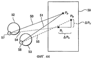
В-третьих, на стр. 5, строки 25-44 патентного документа 3, пояснение «фиг. 2» документа не относится к оптической системе для бинокулярного зрения. Этот чертеж показан на фиг. 44. На фиг. 44, когда глазные яблоки 57 и 58 смотрят прямо в точку РР на поверхности 59 объекта, линии визирования 50 и 51 направлены в точку РР. Очковые линзы 52 и 53 расположены прямо перед глазными яблоками 57 и 58. За счет призменного эффекта очковых линз 52 и 53, для левого глаза 57 наблюдается, что точка РР размещена в точке PL пересечения линии визирования 54 и поверхности 59, а для правого глаза 58 наблюдается, что точка РР размещена в точке PR пересечения линии визирования 58 и поверхности 59. В строках 41-42 на той же странице описано, что соотношение между линиями визирования, показанными на фиг. 44, может считаться как для одной очковой линзы, которая симметрична относительно начального меридиана. Однако, как можно видеть из формулы Прентиса (Р=(h×D)/10), призменный эффект пропорционален диоптрической (преломляющей) силе. Поэтому данное утверждение справедливо только для линз, когда левая линза и правая линза идентичны.Thirdly, on
Дополнительно, формула Прентиса является приближенной формулой, которая достаточна для простого использования и означает, что Р призмы для линзы пропорционально расстоянию h (в мм) от центра и диоптрии D. Одним словом, поскольку оптическая сила левой линзы и правой линзы в общем случае различны, вышеописанное утверждение не очевидно и не установлено. Далее, после объяснения «фиг. 2» в патентном документе 3 объяснения основываются на одной из левой линзы и правой линзы на протяжении всего документа без определения системы координат и начала отсчета, которые определяют целевую точку РР. Поэтому данная конфигурация не подходит для оптической системы для бинокулярной функции.Additionally, the Prentice formula is an approximate formula that is sufficient for simple use and means that the P prisms for the lens are proportional to the distance h (in mm) from the center and diopter D. In short, since the optical power of the left lens and the right lens are generally different, The above statement is neither obvious nor established. Further, after explaining “FIG. 2 ”in
В-четвертых, степень искажения, показанного на «фиг. 4» патентного документа 3, трудно понять. Эта фигура показана на фиг. 45. Объяснение этой фигуры в патентном документе 3 приведено в строке 17 в правом столбце на стр. 5, где поясняется, что эта фигура есть отображение, полученное на эквидистантной и симметричной решетке. «Фиг. 4» в этом документе представляет собой фигуру, на которой позиционные различия начерчены из точки Р, когда узловая точка сетки решетки установлена в точку Р, и, в частности, можно видеть, что она искажена в левой периферийной части. В строках 25-27 того же столбца патентного документа 3 поясняется, что это есть седловидное искажение или бочкообразное искажение. А именно, в патентном документе 1 раскрывается, что имеется соотношение между позиционными различиями в горизонтальном направлении, ΔРН, и искажением. Если предполагается, что имеется соотношение между позиционными различиями в горизонтальном направлении, ΔРН, и искажением, то решетка должна быть искажена, когда все линии визирования 54 и 55 имеют точки пересечения иные, чем точка Р на поверхности 59. Однако в этом случае, поскольку позиционные различия в горизонтальном направлении равны 0, возникает противоречие, состоящее в том, что вышеописанная «фиг. 4» становится фигурой, которая не искажена. Поэтому позиционные различия в горизонтальном направлении, ΔРН, не имеют соотношения с искажением. Далее, описано, что искаженная фигура обрабатывается как изображение, построенное прямыми линиями в мозгу. Однако не описана база относительно того, до какой степени фигура искажена, фигура может обрабатываться как линии, хотя это важный вопрос. Поэтому невозможно ясно понять, становится ли искажение, показанное на фиг. 45, прямыми линиями в мозгу, или нет.Fourth, the degree of distortion shown in “FIG. 4 ”
В-пятых, предмет (визирная метка) находится на поверхности. В принципе, визирная метка произвольно определяется разработчиком. Поэтому в общем случае очковые линзы проектируются так, что рабочие показатели очковых линз становятся выше при произвольной визирной метке, определенной разработчиком. Однако в патентном документе 3 метод оценивания ограничен возможными вариантами визирных меток, которые приняты для очковых линз для считывания знаков на плотной газетной бумаге или на стене. Точки в пределах визирной метки иной, чем точка фиксации в патентном документе 3, имеют большие различия в расстояниях от обоих глазных яблок. Поэтому становится затруднительным одновременно отъюстировать ошибку в увеличении из точки фиксации, остаточный астигматизм и призму. Следовательно, призма становится большей. Поэтому в системе, в которой визирная метка находится на поверхности, трудно оценивать бинокулярное зрение.Fifthly, an object (target mark) is on the surface. In principle, the target mark is arbitrarily determined by the developer. Therefore, in the general case, spectacle lenses are designed so that the performance of the spectacle lenses becomes higher with an arbitrary target mark defined by the developer. However, in
В патентном документе 4 предложен способ проектирования для очковых линз. В этом способе проектирования рассматривается состояние, в котором направление главного вида лица, носящего очки, сдвигается к стороне доминирующего глаза. Если сдвиг, описанный в патентном документе 2, справедлив для близорукости, то это представляет собой интересное явление и, естественно, должно иметься новшество, которое использует данное физиологическое явление. Однако патентный документ 4 включает проблемы, описанные ниже.
Во-первых, объект, подлежащий измерению, является живым телом. Таким образом, имеется проблема в точности измерения. В примере, описанном в абзаце 0030 патентного документа 4, указано, что сдвиг соответствует 2 см. Если это 2 см, то его легко измерить, но если сдвиг меньше, то становится затруднительным выполнить стабильное измерение. В абзаце 0063 патентного документа 4 описано, что он может быть измерен с «абсолютной ошибкой, меньшей или равной 3 мм». Однако, принимая во внимание, что обычная величина вставки для близорукости в линзе с прогрессивной (плавно изменяющейся) оптической силой равна 2,5 мм, величина ошибки очень велика.First, the object to be measured is a living body. Thus, there is a problem in the accuracy of the measurement. In the example described in paragraph 0030 of
Вторая проблема состоит в том, что явление «направление главного вида сдвигается к стороне доминирующего глаза» противоречит закону Геринга об одинаковых иннервациях, что является единственным законом относительно бинокулярных движений глаз. Трудно улучшить бинокулярную функцию путем проектирования очковых линз через меру, которая основана на явлении, противоречащем закону Геринга об одинаковых иннервациях. Дополнительно, объяснение закона Геринга об одинаковых иннервациях можно видеть в непатентном документе 15 (авторов Ryorji Osaka, Sachio Nakamizo, Kazuo Koga, “Binocular Movement and Hering Theory, Experimental Psychology of eye movement”, The University of Nagoya Press (1993), глава 3, с.60-61, написанная Sachio Nakamizo). Теория Геринга относительно бинокулярного движения состоит из гипотезы, что существуют иннервация содружественного поворота (глазных яблок) (ипсилатеральное бинокулярное движение), которая генерирует бинокулярное движение, и иннервация вергентных движений глаз (контралатерального бинокулярного движения), гипотезы об одинаковых иннервациях обоих глаз, то есть величины иннерваций, относящихся к соответствующим глазам, всегда равны (закон Геринга), и гипотезы аддитивности иннерваций, то есть аддитивность справедлива для этих двух типов иннерваций.The second problem is that the phenomenon “the direction of the main view shifts to the side of the dominant eye” contradicts Goering’s law on the same innervations, which is the only law regarding binocular eye movements. It is difficult to improve the binocular function by designing spectacle lenses through a measure that is based on a phenomenon that contradicts Goering’s law of equal innervations. Additionally, an explanation of Goering’s law on equal innervations can be seen in Non-Patent Document 15 (authors Ryorji Osaka, Sachio Nakamizo, Kazuo Koga, “Binocular Movement and Hering Theory, Experimental Psychology of eye movement”, The University of Nagoya Press (1993),
Кроме того, как отличающееся мнение, известно, что центр вращения не фиксирован, а движется, а также смещается во время движения глазного яблока. Известно, что центр вращения не вращается, когда он центрирован в одной точке, и он вращается, когда он центрирован в различных точках в зависимости от его использования. Утверждение «сдвиг направления главного вида» в патентном документе 4 может быть объяснено из того факта, что центр вращения глазного яблока сам сдвигается. А именно, когда учитывается, что центры вращения движутся, средняя точка между центрами вращения левого и правого глазных яблок также движется, и направление главного вида также движется. Таким образом, считается, что предположение о том, что левое и правое глазное яблоко движутся симметрично, лучше согласуется с физиологическим фактом, чем предположение о том, что левое и правое глазное яблоко движутся асимметрично, что утверждается в патентном документе 2.In addition, as a differing opinion, it is known that the center of rotation is not fixed, but moves, and also moves during the movement of the eyeball. It is known that the center of rotation does not rotate when it is centered at one point, and it rotates when it is centered at various points depending on its use. The statement “main direction shift” in
В третьих, в абзаце 0039 патентного документа 2 указано, что «обеспечивается превосходное бинокулярное зрение». Однако степень этого не ясна. Более конкретно, указывается, что если возникающий астигматизм (он рассматривается как остаточный астигматизм) меньше или равен 0,5 диоптрий, то это является комфортабельным полем зрения. Однако ошибка в оптической силе возникает в зависимости от расстояния до предмета. Комфортабельное поле зрения не реализуется, за исключением случая, в котором предполагается, что предмет размещен в позиции, для которой ошибка в оптической силе равна 0. В варианте осуществления согласно патентному документу 4 две фигуры, которые являются фигурой ошибок в оптической силе и фигурой возникающих астигматизмов, показаны в зависимости от условий наблюдения. Однако их балансы не упоминаются. Поэтому едва ли можно понять, могут ли быть получены комфортабельные поля зрения без указания балансов или соотношения между ошибкой в оптической силе и возникающим астигматизмом.Thirdly, in paragraph 0039 of
Далее, является некорректным утверждать, что «бинокулярное зрение становится лучше» путем показа с помощью диаграмм только ошибок в оптической силе и возникающего астигматизма. Нарушение, в котором бинокулярное зрение теряется, даже если левый и правый глаза получают хорошие возможности для зрения, может быть найдено главным образом у многих пациентов, страдающих косоглазием. При обычном оценивании ошибки в оптической силе и астигматизме, таком как оценивание, описанное в этом патентном документе 4, оценивание рабочих показателей, специфических для бинокулярного зрения, не пригодно.Further, it is incorrect to say that “binocular vision is getting better” by showing with the help of diagrams only errors in optical power and arising astigmatism. A disorder in which binocular vision is lost, even if the left and right eyes get good vision, can be found mainly in many patients with strabismus. In the usual estimation of errors in optical power and astigmatism, such as the evaluation described in this
В-четвертых, как в случае патентного документа 3, предметом согласно этому патенту является поверхность, как видно из «фиг.1» или «фиг.4» патентного документа 4. А именно, можно сделать вывод, подобный сделанному в четвертом пункте относительно патентного документа 3.Fourth, as in the case of
В патентном документе 5 раскрыт метод относительно очковой линзы так называемого изогнутого (полусферического) типа, причем линза изогнута от ее передней к задней стороне. Далее, на стр. 13 или стр. 15 патентного документа 5 имеются некоторые описания относительно внеосевого призматического несоответствия (диспарантности). Здесь главным образом описаны дефекты, касающиеся бинокулярного зрения, причем бинокулярное зрение является темой в патентном документе 5.
Во-первых, описано, что методы, раскрытые в патентном документе 5, являются методами для очковой линзы полусферического типа или очковой линзы защитных очков. Однако их конфигурации не ясны. В основном изобретении, описанном в патентном документе 5, предполагается, что имеется предписанная зона и периферийная височная зона. Различие между этими двумя зонами заключается в формах поверхностей, как описано на стр. 28-30 патентного документа 5. Здесь способ объяснения различия не основан на оценивании путем вычислений трассировки лучей, которые обычно используются в настоящее время, но это упрощенный способ, который вычисляет исходя из формы поверхности линзы, как использовалось для объяснения линзы с плавным изменением оптической силы (прогрессивной линзы) в прошлом. Поэтому преломляющая сила и астигматизм являются выведенными значениями кривой, которые вычисляются из производных поверхности. Таким образом, они отличаются от значений, вычисленных путем трассировки лучей. Далее, аналогичным образом не имеется описания относительно учета закона Листинга о движении глазного яблока, который обычно принимается во внимание при проектировании в настоящее время. Поэтому это является отличным от оценивания или проектирования, которое основывается на физиологической базе, такой как закон Листинга. Далее, периферийная височная зона является настолько произвольной, что различие от предписанной зоны становится неясным. Таким образом, периферийная височная зона не формирует ограничивающее условие. Поэтому может считаться, что описание является справедливым только для нормального проектирования линзы.Firstly, it is described that the methods disclosed in
Во-вторых, относительно определения внеосевого призматического несоответствия, описанного в нижней части страницы 13 патентного документа 5, только указано, что «дефект в бинокулярном зрении возникает, когда астигматизм в височной части и астигматизм в назальной части не равны». Однако описание является недостаточным и невозможно понять, какой астигматизм упоминается. Кроме того, в качестве способа коррекции внеосевого призматического несоответствия, имеется только описание на странице 15 патентного документа 5, что принимается асферическая поверхность. Таким образом, описание является недостаточным. Кроме того, хотя понятно, что оценивание выполняется с единственной очковой линзой, на странице 13 патентного документа 5 утверждается, что «имеется дефект в бинокулярном зрении». Причина этого вывода не ясна.Secondly, regarding the definition of off-axis prismatic mismatch described at the bottom of
В-третьих, на странице 15 патентного документа 5, упоминаются юстировка относительно преломляющей силы, астигматизма, призменного несоответствия, баланс элементов для оптической коррекции. Однако описание того, что дефект бинокулярного зрения является допустимым, если дефект находится в пределах значений таблицы на странице 15, невозможно понять. Можно прочитать из этой таблицы, что величина коррекции снижается по мере того как предписанная оптическая сила линзы становится больше. Можно прочитать, что ошибка в достаточной степени корректируется с помощью малой коррекции и дефект в бинокулярном зрении является приемлемым, что означает, что, когда предписанная оптическая сила линзы становится больше, допуск для пациента по бинокулярному зрению становится больше. Это утверждение трудно понять, поскольку это описание допуска основано на оценивании одного глаза. Исходя из сущности патентного документа 5, в котором даже не раскрыт способ определения допуска бинокулярного зрения, трудно прогнозировать, возможно ли проектировать так, что допуск меньше или равен этому допуску, как в случае стандартных или нормальных очковых линз. А именно, не просто применять этот допуск к проектированию линзы с другим общим предписанием, базируясь на описании такого допуска в состоянии, в котором бинокулярное зрение даже не определено.Thirdly, on
Здесь представляется, что оценивание бинокулярного зрения через оценивание одного глаза основано на причине, что височная часть и назальная часть должны быть равны, поскольку, если смотреть вправо, правая височная часть используется в правой линзе и назальная часть используется в левой линзе. Однако это случай, когда имеется предварительное условие, что левая линза и правая линза являются одинаковыми, например, как это имеет место в третьей проблеме патентного документа 1. Такое предписание является очень редким. Далее, предположим случай, в котором утверждается, что предписания для левого глаза и правого глаза являются почти одинаковыми. В этом случае, принимая во внимание, что предел чувствительности по углу сенсорной фузии равен около 10 секунд по углу, трудно захватить бинокулярное зрение при такой грубой концепции. Более того, когда применяются универсальные линзы, является проблематичным применить оценивание и проектирование, которые основаны на таком допуске, у которого отсутствует физиологическая основа, к человеческому телу, даже если левое и правое предписания известны заранее. В результате, имеется риск того, что будет иметь место дискомфорт или повысится утомляемость.Here it seems that the evaluation of binocular vision through the evaluation of one eye is based on the reason that the temporal part and the nasal part should be equal, because when viewed to the right, the right temporal part is used in the right lens and the nasal part is used in the left lens. However, this is a case where there is a precondition that the left lens and the right lens are the same, for example, as is the case in the third issue of
Сущность изобретенияSUMMARY OF THE INVENTION
Ввиду вышеописанных проблем целями настоящего изобретения является качественно оценить рабочие показатели бинокулярного зрения на основе физиологического знания, предложить функцию оценивания, в которой принимаются во внимание результаты оценивания, и выполнять оценивания и изготавливать очковые линзы, которые являются превосходными по рабочим показателям бинокулярного зрения.In view of the above problems, the objectives of the present invention is to qualitatively evaluate the performance of binocular vision based on physiological knowledge, to offer a rating function that takes into account the results of the evaluation, and to evaluate and produce spectacle lenses that are excellent in performance of binocular vision.
Для решения вышеописанной проблемы, согласно способу проектирования очковых линз в соответствии с настоящим изобретением: когда положительная относительная конвергенция, отрицательная относительная конвергенция, положительная относительная аккомодация, отрицательная относительная аккомодация, вертикальная фузионная вергенция (одновременное движение зрачков друг к другу или друг от друга при фокусировке), которые являются индивидуальными значениями измерения, относящимися к бинокулярному зрению, определены в качестве относительных значений измерения, по меньшей мере одна или обе из положительной относительной конвергенции и отрицательной относительной конвергенции включаются в индивидуальное относительное значение измерения. Способ содержит определение оптических проектных значений для очковых линз путем оптимизации бинокулярного зрения при использовании, в качестве функции оценивания для оптимизации, функции, полученной путем суммирования функций остроты бинокулярного зрения, включая относительные значения измерения в качестве факторов в соответствующих оцениваемых точках объекта.To solve the above problem, according to the method of designing spectacle lenses in accordance with the present invention: when the positive relative convergence, negative relative convergence, positive relative accommodation, negative relative accommodation, vertical fusional vergence (simultaneous movement of the pupils to each other or from each other when focusing) which are individual measurement values related to binocular vision are defined as relative s measurement values, at least one or both of the positive relative convergence and the negative relative convergence included in the individual relative measurement value. The method comprises determining optical design values for spectacle lenses by optimizing binocular vision when using, as an evaluation function for optimization, a function obtained by summing the functions of visual acuity of binocular vision, including relative measurement values as factors at the corresponding estimated points of the object.
Способ изготовления очковых линз согласно настоящему изобретению содержит изготовление очковых линз на основе оптических проектных значений, определенных вышеописанным способом проектирования очковых линз. Способ оценивания очковых линз согласно настоящему изобретению включает в себя оценивание бинокулярного зрения с использованием в качестве функции оценивания для оптимизации, функции, полученной путем суммирования вышеописанных функций остроты бинокулярного зрения, включая относительные значения измерения в качестве факторов в соответствующих оцениваемых точках.A method for manufacturing eyeglass lenses according to the present invention comprises manufacturing eyeglass lenses based on optical design values determined by the above-described method for designing eyeglass lenses. The method for evaluating eyeglass lenses according to the present invention includes evaluating binocular vision using, as an evaluation function for optimization, a function obtained by summing the above-described binocular visual acuity functions, including relative measurement values as factors at the respective estimated points.
Система изготовления очковых линз согласно настоящему изобретению является системой, в которой компьютер заказывающей стороны, имеющий функцию исполнения процесса для заказа очковых линз и инсталлированный на заказывающей очковые линзы стороне, компьютер изготавливающей стороны, имеющий функцию приема информации от компьютера заказывающей стороны и исполняющий процесс, необходимый для приема заказа на очковые линзы, соединены через сеть. Компьютер заказывающей стороны передает информацию, необходимую для проектирования очковых линз, включающую в себя по меньшей мере одну или обе из положительной относительной конвергенции и отрицательной относительной конвергенции, на компьютер изготавливающей стороны. Компьютер изготавливающей стороны содержит: модуль ввода данных, в который вводятся данные, включающие в себя относительное значение измерения, переданное от компьютера заказывающей стороны; модуль вычисления функции остроты бинокулярного зрения, который вычисляет значения оптических рабочих показателей во множестве оцениваемых точек очковых линз на основе введенных данных; модуль оптимизации оцененных значений, который оптимизирует значения оптических рабочих показателей с использованием в качестве функции оценивания, функции, полученной путем суммирования функций остроты бинокулярного зрения, включая в качестве факторов относительные значения измерения, включая по меньшей мере одну или обе из положительной относительной конвергенции и отрицательной относительной конвергенции; модуль оценивания функции оценивания, который оценивает значения оптических рабочих показателей путем сравнения функции оценивания с предварительно определенным порогом; модуль коррекции проектных данных, который корректирует проектные данные, если значения функций остроты бинокулярного зрения не достигают предварительно определенного условия конвергенции как результата оценивания посредством модуля оценивания оценочных значений; и модуль определения оптических проектных значений, который определяет проектные данные на основе результата оценивания, завершенного для каждой оцениваемой точки с помощью модуля оценивания функции оценивания; и модуль вывода проектных данных, который выдает окончательные проектные данные, полученные модулем определения оптических проектных значений, на устройство для обработки линзы.An eyeglass lens manufacturing system according to the present invention is a system in which a ordering party computer having a process execution function for ordering eyeglass lenses and installed on a side ordering an eyeglass lenses, a manufacturing party computer having a function of receiving information from an ordering party computer and executing a process necessary for receiving an order for spectacle lenses connected through a network. The ordering party computer transmits the information necessary for designing the eyeglass lenses, including at least one or both of the positive relative convergence and the negative relative convergence, to the computer of the manufacturing side. The manufacturer’s computer includes: a data input module into which data is entered, including a relative measurement value transmitted from the ordering party’s computer; a binocular visual acuity function calculation module that calculates optical performance values in a plurality of evaluated points of spectacle lenses based on the inputted data; an estimated value optimization module that optimizes optical performance values using, as an evaluation function, a function obtained by summing the binocular visual acuity functions, including, as factors, relative measurement values, including at least one or both of positive relative convergence and negative relative convergence; an evaluation function evaluation module that evaluates optical performance values by comparing the evaluation function with a predetermined threshold; a design data correction module that corrects design data if the values of the binocular visual acuity functions do not reach a predetermined convergence condition as a result of evaluation by the evaluation value evaluation module; and a module for determining optical design values, which determines the design data based on the evaluation result completed for each point to be evaluated using the evaluation module of the evaluation function; and a design data output module that provides final design data obtained by the optical design value determination module to the lens processing device.
Очковые линзы в соответствии с изобретением изготавливаются вышеописанным способом изготовления очковых линз и системой изготовления очковых линз.Spectacle lenses in accordance with the invention are manufactured by the above-described manufacturing method of spectacle lenses and the manufacturing system of spectacle lenses.
В настоящем изобретении является предпочтительным: классифицировать на зону, в которой фузия невозможна, и на фузионную зону в качестве пороговых значений для функции остроты бинокулярного зрения, включающей относительное значение измерения, как фактор; определить меньшее значение функций зрения левого и правого глазных яблок, в качестве функции остроты бинокулярного зрения в зоне, в которой фузия невозможна; и определить значение, полученное вычитанием значения улучшения остроты бинокулярного зрения из меньшего значения функций зрения левого и правого глазных яблок, в качестве функции остроты бинокулярного зрения в фузионной зоне.In the present invention, it is preferable: to classify into a zone in which fusion is not possible, and into a fusion zone as threshold values for a function of binocular visual acuity, including a relative measurement value, as a factor; determine the smaller value of the visual functions of the left and right eyeballs, as a function of the acuity of binocular vision in the area in which fusion is impossible; and determine the value obtained by subtracting the value of improving the acuity of binocular vision from the smaller value of the visual functions of the left and right eyeballs, as a function of the acuity of binocular vision in the fusion zone.
Когда трехмерное пространство, в котором горизонтальная ось представляет угол конвергенции, вертикальная ось представляет вертикальную фузионную вергенцию двигательной фузии и ось глубины представляет ось аккомодации, рассматривается для классификации на зону, в которой фузия невозможна, и на фузионную зону является предпочтительным, чтобы классификация на зону, в которой фузия невозможна, и на фузионную зону выполнялась с использованием в качестве критериев внутренней стороны и внешней стороны замкнутой поверхности, определяемой с использованием относительных значений измерения в качестве порогов.When a three-dimensional space in which the horizontal axis represents the convergence angle, the vertical axis represents the vertical fusion vergence of the motor fusion and the depth axis represents the accommodation axis, is considered for classification into a zone in which fusion is not possible, and into a fusion zone, it is preferable that classification into a zone in which fusion is impossible, and the fusion zone was performed using as criteria internal side and external side of a closed surface, defined with using relative measurement values as thresholds.
Является предпочтительным: определить в качестве порога 1/3 положительной относительной конвергенции или отрицательной относительной конвергенции относительного значения измерения по оси угла конвергенции; и получить аберрацию конвергенции как разность между углом конвергенции в точке оценивания и опорным значением угла конвергенции, которое является углом конвергенции линии фиксации прохождения через проектные опорные точки очковых линз. Кроме того, является предпочтительным: получить параллельный плоскости компонент, который включает в себя срединную линию линии фиксации, посредством которой получают угол конвергенции в оцениваемой точке и которая является проекцией на плоскость, перпендикулярную срединной плоскости; определить в качестве решающего критерия относительной конвергенции сравнительное значение между параллельным плоскости компонентом аберрации конвергенции и порогом; и классифицировать на зону, в которой фузия невозможна, и на фузионную зону. «Срединная линия», как используется здесь, означает линию, которая, будучи представленной направляющим косинусом, проходит через срединную точку (точку отсчета) центра вращения левого и правого глазных яблок на стороне изображения и проходит через оцениваемую точку объекта на стороне объекта. То есть «срединная линия» есть линия, имеющая среднее значение направляющего косинуса линии фиксации левого и правого глазных яблок.It is preferable: to determine as a
1/3 от положительной относительной аккомодации или отрицательной относительной аккомодации относительного значения измерения может быть определена как порог по оси аккомодации, и сравнительное значение между средней диоптрической ошибкой, полученной в оцениваемой точке, и порогом может быть определено в качестве решающего критерия, чтобы классифицировать на зону, в которой фузия невозможна, и на фузионную зону.1/3 of the positive relative accommodation or negative relative accommodation of the relative measurement value can be defined as a threshold along the axis of accommodation, and the comparative value between the average diopter error obtained at the estimated point and the threshold can be determined as a decisive criterion to classify into a zone in which fusion is not possible, and to the fusion zone.
Является предпочтительным: определить в качестве порога 1/3 вертикальной фузионной вергенции относительных значений измерения по оси вертикальной фузионной вергенции двигательной фузии; получить аберрацию конвергенции, определенную как разность между углом конвергенции в оцениваемой точке и опорным значением угла конвергенции, которое является углом конвергенции в проектной опорной точке; получить вертикальный к плоскости компонент, который включает в себя срединную линию линии фиксации, для которой получен угол конвергенции оцениваемой точки и которая является проекцией на плоскость, параллельную срединной плоскости; определить в качестве решающего критерия вертикальной фузионной вергенции сравнительное значение между вертикальным к плоскости компонентом аберрации конвергенции и порогом; и классифицировать на зону, в которой фузия невозможна, и на фузионную зону. Предпочтительно классифицировать на внутреннюю сторону двигательной фузионной зоны, удовлетворяющей критерию двигательной фузии, если все решающие критерии относительной конвергенции, относительной аккомодации и вертикальной фузионной вергенции удовлетворяются одновременно; и классифицировать на зону, в которой фузия невозможна, если по меньшей мере один из решающих критериев не удовлетворен.It is preferable: to determine as a
Как описано выше, согласно изобретению фокусируется внимание на рабочих показателях бинокулярного зрения из рабочих показателей бинокулярного зрения при ношении очков, и если значение измерения, относящееся к рабочему показателю бинокулярного зрения, определено как «относительное значение измерения», то относительное значение измерения включает в себя по меньшей мере одну или обе из положительной относительной конвергенции и отрицательной относительной конвергенции. Таким образом, предложена функция остроты бинокулярного зрения, включающая в себя относительное значение измерения в качестве фактора, и функции остроты бинокулярного зрения суммируются вместе в соответствующих оцениваемых точках объекта. Путем выполнения оптимизации с использованием суммарных функций в качестве функции оценивания выполняется оценивание и проектирование очковых линз.As described above, according to the invention, attention is focused on the binocular vision performance from the binocular vision performance when wearing glasses, and if the measurement value related to the binocular vision performance is defined as “relative measurement value”, then the relative measurement value includes at least one or both of positive relative convergence and negative relative convergence. Thus, a function of binocular visual acuity is proposed, which includes the relative value of the measurement as a factor, and binocular visual acuity functions are summarized together at the corresponding estimated points of the object. By performing optimization using summary functions as an evaluation function, evaluation and design of spectacle lenses is performed.
Как описано, например, в “Relationship between visual fatigue and inconsistency between a focus adjustment and convergence of both eyes in a three-dimensional image vision”, Masaki Emoto, Visual Science, vol. 24, No. 1 (2003), p.13, относительное значение измерения в высокой степени связано с двигательной фузией и зрительным утомлением, и меньшее относительное значение измерения вызывает утомление. Автор настоящего изобретения сфокусировал внимание на вышеописанном факте и обнаружил, что очковые линзы, спроектированные, чтобы не превышать порог относительного значения измерения, становятся комфортабельными для носящего очки. Поэтому в соответствии с изобретением, относительные значения измерения получаются от заказывающей стороны. Если относительное значение измерения является одной или обеими из положительной относительной конвергенции или отрицательной относительной конвергенции, другие значения получаются из одной или обеих из положительной относительной конвергенции или отрицательной относительной конвергенции. Если относительное значение измерения не может быть получено от заказывающей стороны, то относительное значение измерения может быть аппроксимировано исходя из возраста и аппроксимированное значение может быть использовано в качестве относительного значения измерения, что также входит в объем изобретения. Путем использования оценивания и проектирования при вводе относительного значения измерения, полученного, как описано выше, в функцию оценивания, становится возможным улучшить рабочие показатели бинокулярного зрения очковых линз.As described, for example, in “Relationship between visual fatigue and inconsistency between a focus adjustment and convergence of both eyes in a three-dimensional image vision”, Masaki Emoto, Visual Science, vol. 24, No. 1 (2003), p.13, the relative measurement value is highly associated with motor fusion and visual fatigue, and a lower relative measurement value causes fatigue. The author of the present invention focused on the above fact and found that spectacle lenses designed to not exceed the threshold of the relative measurement value become comfortable for the wearer. Therefore, in accordance with the invention, relative measurement values are obtained from the ordering party. If the relative measurement value is one or both of positive relative convergence or negative relative convergence, the other values are obtained from one or both of positive relative convergence or negative relative convergence. If the relative measurement value cannot be obtained from the ordering party, then the relative measurement value can be approximated based on age and the approximated value can be used as the relative measurement value, which is also included in the scope of the invention. By using evaluation and design, when entering the relative measurement value obtained as described above into the evaluation function, it becomes possible to improve the performance of binocular vision of spectacle lenses.
В соответствии с настоящим изобретением с использованием функций зрения обоих глаз, что включает в себя относительные значения измерения, являющиеся значениями измерения, относящимися к бинокулярному зрению, становится возможным предоставить очковые линзы, которые улучшают рабочие показатели бинокулярного зрения.In accordance with the present invention, using the vision functions of both eyes, which includes relative measurement values, which are measurement values related to binocular vision, it is possible to provide spectacle lenses that improve the performance of binocular vision.
Краткое описание чертежейBrief Description of the Drawings
Фиг. 1 - блок-схема системы изготовления в соответствии с вариантом осуществления способа изготовления очковых линз согласно настоящему изобретению.FIG. 1 is a flowchart of a manufacturing system in accordance with an embodiment of a method for manufacturing spectacle lenses according to the present invention.
Фиг. 2 - функциональная блок-схема, показывающая функцию компьютера стороны изготовления в системе изготовления в соответствии с вариантом осуществления способа изготовления очковых линз согласно настоящему изобретению.FIG. 2 is a functional block diagram showing a function of a computer of a manufacturing side in a manufacturing system according to an embodiment of a method for manufacturing spectacle lenses according to the present invention.
Фиг. 3 - диаграмма, показывающая последовательность операций в соответствии с вариантом осуществления способа изготовления очковых линз.FIG. 3 is a diagram showing a flowchart in accordance with an embodiment of a method for manufacturing spectacle lenses.
Фиг. 4 - диаграмма, показывающая относительное поле зрения по отношению к положению на сетчатке.FIG. 4 is a diagram showing the relative field of view with respect to the position on the retina.
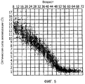
Фиг. 5 - диаграмма Дуэйна (Duane), показывающая соотношение между возрастом и аккомодацией по Дуэйну.FIG. 5 is a Duane chart showing the relationship between age and accommodation according to Duane.
Фиг. 6 - диаграмма, показывающая зону комфорта, выведенную из диаграммы Петерса (Peters) для возраста 5-15 лет.FIG. 6 is a diagram showing a comfort zone derived from a Peters diagram for an age of 5-15 years.
Фиг. 7 - диаграмма Петерса, показывающая зону комфорта, выведенную из диаграммы для возраста 25-35 лет.FIG. 7 is a Peters chart showing a comfort zone derived from a chart for an age of 25-35 years.
Фиг. 8 - диаграмма, показывающая зону комфорта, выведенную из диаграммы Петерса для возраста 45-55 лет.FIG. 8 is a diagram showing a comfort zone derived from a Peters diagram for an age of 45-55 years.
Фиг. 9 - диаграмма, показывающая зону комфорта, выведенную из диаграммы Петерса для возраста 75 лет.FIG. 9 is a diagram showing a comfort zone derived from a Peters diagram for an age of 75 years.
Фиг. 10 - диаграмма, показывающая систему объект - очковая линза - глазное яблоко для пояснения «объекта», используемого в варианте осуществления способа оценивания очковой линзы согласно настоящему изобретению.FIG. 10 is a diagram showing an object — eyeglass lens — eyeball system for explaining an “object” used in an embodiment of a method for evaluating an eyeglass lens according to the present invention.
Фиг. 11 - диаграмма, показывающая опорное значение угла конвергенции стороны изображения в системе объект - очковая линза - глазное яблоко, используемой в варианте осуществления способа оценивания очковой линзы согласно настоящему изобретению.FIG. 11 is a diagram showing a reference value of an angle of convergence of an image side in an object-eyeglass-eyeball system used in an embodiment of the method for evaluating an eyeglass lens according to the present invention.
Фиг. 12 - диаграмма, показывающая опорное значение угла конвергенции стороны объекта в системе объект - очковая линза - глазное яблоко, используемой в варианте осуществления способа оценивания очковой линзы согласно настоящему изобретению.FIG. 12 is a diagram showing a reference value of an angle of convergence of an object side in an object-eyeglass lens-eyeball system used in an embodiment of the method for evaluating an eyeglass lens according to the present invention.
Фиг. 13 - пояснительная диаграмма перпендикулярного к поверхности направления аберрации сходимости, определенной на стороне изображения, причем пояснительная диаграмма показывает систему объект - очковая линза - глазное яблоко, показанную на фиг. 11, используемую в варианте осуществления способа оценивания очковой линзы согласно настоящему изобретению, с перпендикулярного направления по отношению к срединной плоскости.FIG. 13 is an explanatory diagram of the direction of convergence aberration perpendicular to the surface defined on the image side, and the explanatory diagram shows an object-eyeglass lens-eyeball system shown in FIG. 11 used in an embodiment of a method for evaluating an eyeglass lens according to the present invention from a perpendicular direction with respect to the median plane.
Фиг. 14 - пояснительная диаграмма перпендикулярного к поверхности направления аберрации сходимости, определенной на стороне объекта, причем пояснительная диаграмма показывает систему объект - очковая линза - глазное яблоко, показанную на фиг. 12, используемую в варианте осуществления способа оценивания очковой линзы согласно настоящему изобретению, с перпендикулярного направления по отношению к срединной плоскости.FIG. 14 is an explanatory diagram of the direction of convergence aberration perpendicular to the surface defined on the side of the object, and the explanatory diagram shows the object-eyeglass lens-eyeball system shown in FIG. 12 used in an embodiment of a method for evaluating an eyeglass lens according to the present invention from a perpendicular direction with respect to the median plane.
Фиг. 15 - диаграмма, показывающая угол конвергенции на стороне изображения в оцениваемой точке системы объект - очковая линза - глазное яблоко, используемой в варианте осуществления способа оценивания очковой линзы согласно настоящему изобретению.FIG. 15 is a diagram showing an angle of convergence on the image side at an estimated point of the object — eyeglass lens — eyeball system used in an embodiment of the eyeglass lens assessment method of the present invention.
Фиг. 16 - диаграмма, показывающая угол конвергенции на стороне объекта в оцениваемой точке системы объект - очковая линза - глазное яблоко, используемой в варианте осуществления способа оценивания очковой линзы согласно настоящему изобретению.FIG. 16 is a diagram showing an angle of convergence on the object side at an estimated point of the object — eyeglass lens — eyeball system used in an embodiment of the eyeglass lens assessment method of the present invention.
Фиг. 17 - диаграмма, показывающая конфигурацию системы объект - очковая линза - глазное яблоко, в сравнительном примере.FIG. 17 is a diagram showing a configuration of an object-eyeglass lens-eyeball system in a comparative example.
Фиг. 18 - диаграмма, показывающая параллельный поверхности компонент аберрации конвергенции варианта осуществления 1 в способе оценивания очковой линзы согласно настоящему изобретению.FIG. 18 is a diagram showing a surface parallel component of the convergence aberration of
Фиг. 19 - диаграмма, показывающая перпендикулярный поверхности компонент аберрации конвергенции варианта осуществления 1 в способе оценивания очковой линзы согласно настоящему изобретению.FIG. 19 is a diagram showing a surface perpendicular component of the convergence aberration of
Фиг. 20 - диаграмма, показывающая поле фиксации через очковые линзы для обоих глаз варианта осуществления 1 в способе оценивания очковой линзы согласно настоящему изобретению.FIG. 20 is a diagram showing a fixation field through spectacle lenses for both eyes of
Фиг. 21 - диаграмма, показывающая значения зрительных функций для обоих глаз варианта осуществления 1 в способе оценивания очковой линзы согласно настоящему изобретению.FIG. 21 is a diagram showing visual function values for both eyes of
Фиг. 22 - диаграмма, показывающая параллельный поверхности компонент аберрации конвергенции варианта осуществления 2 в способе оценивания очковой линзы согласно настоящему изобретению.FIG. 22 is a diagram showing a surface parallel component of the convergence aberration of
Фиг. 23 - диаграмма, показывающая перпендикулярный поверхности компонент аберрации конвергенции варианта осуществления 2 в способе оценивания очковой линзы согласно настоящему изобретению.FIG. 23 is a diagram showing a surface perpendicular component of the convergence aberration of
Фиг. 24 - диаграмма, показывающая поле фиксации через очковые линзы для обоих глаз варианта осуществления 2 в способе оценивания очковой линзы согласно настоящему изобретению.FIG. 24 is a diagram showing a fixation field through spectacle lenses for both eyes of
Фиг. 25 - диаграмма, показывающая значения функций зрения для обоих глаз варианта осуществления 2 в способе оценивания очковой линзы согласно настоящему изобретению.FIG. 25 is a diagram showing values of vision functions for both eyes of
Фиг. 26 - диаграмма, показывающая параллельный поверхности компонент аберрации конвергенции варианта осуществления 3 в способе оценивания очковой линзы согласно настоящему изобретению.FIG. 26 is a diagram showing a surface parallel component of the convergence aberration of
Фиг. 27 - диаграмма, показывающая перпендикулярный поверхности компонент аберрации конвергенции варианта осуществления 3 в способе оценивания очковой линзы согласно настоящему изобретению.FIG. 27 is a diagram showing a surface perpendicular component of the convergence aberration of
Фиг. 28 - диаграмма, показывающая поле фиксации через очковые линзы для обоих глаз варианта осуществления 3 в способе оценивания очковой линзы согласно настоящему изобретению.FIG. 28 is a diagram showing a fixation field through spectacle lenses for both eyes of
Фиг. 29 - диаграмма, показывающая значения функций зрения для обоих глаз варианта осуществления 3 в способе оценивания очковой линзы согласно настоящему изобретению.FIG. 29 is a diagram showing values of vision functions for both eyes of
Фиг. 30 - диаграмма, показывающая параллельный поверхности компонент аберрации конвергенции после оптимизации варианта осуществления 3 в способе оценивания очковой линзы согласно настоящему изобретению.FIG. 30 is a diagram showing the surface parallel components of the convergence aberration after optimization of
Фиг. 31 - диаграмма, показывающая перпендикулярный поверхности компонент аберрации конвергенции после оптимизации варианта осуществления 3 в способе оценивания очковой линзы согласно настоящему изобретению.FIG. 31 is a diagram showing the convergence aberration component perpendicular to the surface after optimization of
Фиг. 32 - диаграмма, показывающая поле фиксации через очковые линзы для обоих глаз после оптимизации варианта осуществления 3 в способе оценивания очковой линзы согласно настоящему изобретению.FIG. 32 is a diagram showing a fixation field through eyeglass lenses for both eyes after optimizing
Фиг. 33 - диаграмма, показывающая значения функций зрения после оптимизации варианта осуществления 3 в способе оценивания очковой линзы согласно настоящему изобретению.FIG. 33 is a diagram showing values of vision functions after optimizing
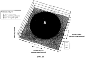
Фиг. 34 - диаграмма Дондерса (Donders) по Hatada.FIG. 34 is a diagram of Donders by Hatada.
Фиг. 35А - диаграмма, показывающая сенсорную фузию, и фиг. 35В - диаграмма, показывающая двигательную фузию.FIG. 35A is a diagram showing sensory fusion, and FIG. 35B is a diagram showing motor fusion.
Фиг. 36A - пример вычислений углов конвергенции, когда межзрачковое расстояние PD составляет 60 мм, и фиг. 36B - пример вычислений углов конвергенции, когда межзрачковое расстояние PD составляет 65 мм.FIG. 36A is an example of calculating convergence angles when the interpupillary distance PD is 60 mm, and FIG. 36B is an example of calculating convergence angles when the interpupillary distance PD is 65 mm.
Фиг. 37 - диаграмма, показывающая фузионную зону Пэнума (Panum) относительно пространственной частоты объекта.FIG. 37 is a diagram showing the fusion zone of a Panum relative to the spatial frequency of an object.
Фиг. 38 - диаграмма, показывающая отношение между горизонтальным относящимся к сетчатке глаза (ретинальным) несоответствием (диспаратностью) и глубиной восприятия.FIG. 38 is a diagram showing the relationship between horizontal retinal (retinal) mismatch (disparity) and depth of perception.
Фиг. 39 - диаграмма (диаграмма Петерса), показывающая отношение между ошибками в преломляющей силе глазных яблок и зрением для исследуемых в возрасте 5-15 лет.FIG. 39 is a diagram (Peters diagram) showing the relationship between errors in the refractive power of eyeballs and vision for subjects aged 5-15 years.
Фиг. 40 - диаграмма (диаграмма Петерса), показывающая отношение между ошибками в преломляющей силе глазных яблок и зрением для исследуемых в возрасте 25-35 лет.FIG. 40 is a diagram (Peters diagram) showing the relationship between errors in the refractive power of eyeballs and vision for subjects aged 25-35 years.
Фиг. 41 - диаграмма (диаграмма Петерса), показывающая отношение между ошибками в преломляющей силе глазных яблок и зрением для исследуемых в возрасте 45-55 лет.FIG. 41 is a diagram (Peters diagram) showing the relationship between errors in the refractive power of eyeballs and vision for those aged 45-55 years.
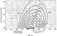
Фиг. 42A - фиг. 42E - пояснительные диаграммы, показывающие деградацию зрения, когда испытуемый, у которого диаграмма Петерса соответствует нормальному зрению, носит очковые линзы обратной силы.FIG. 42A - FIG. 42E are explanatory diagrams showing visual degradation when a subject whose Peters diagram corresponds to normal vision wears retro-power spectacle lenses.
Фиг. 43 - диаграмма, показывающая функцию зрения для единственного глаза, которая получена из диаграммы Петерса для возраста 5-15 лет.FIG. 43 is a diagram showing a vision function for a single eye, which is derived from a Peters diagram for an age of 5-15 years.
Фиг. 44 - диаграмма, показывающая несоответствие на поверхности объекта в обычном методе.FIG. 44 is a diagram showing a mismatch on an object surface in a conventional method.
Фиг. 45 - диаграмма, показывающая искажение в обычном методе.FIG. 45 is a diagram showing distortion in a conventional method.
Подробное описание вариантов осуществленияDetailed Description of Embodiments
Варианты осуществления данного изобретения объяснены ниже, но данное изобретение не ограничено вариантами осуществления, описанными ниже. Оно объясняется в следующем порядке:Embodiments of the present invention are explained below, but the invention is not limited to the embodiments described below. It is explained in the following order:
[1] Варианты осуществления системы изготовления очковых линз и способ изготовления[1] Embodiments of a spectacle lens manufacturing system and manufacturing method
[2] Вариант осуществления способа проектирования очковых линз[2] An embodiment of a method for designing eyeglass lenses
[3] Варианты осуществления[3] Embodiments
Перед конкретным объяснением варианта осуществления настоящего изобретения объяснены технические предположения и термины, используемые в вариантах осуществления.Before a specific explanation of an embodiment of the present invention, technical assumptions and terms used in the embodiments are explained.
Чтобы выполнить оценивание или проектирование очковой линзы в варианте осуществления, необходимо определить проектную опорную точку. Эта проектная опорная точка немного отличается для однофокусной линзы и многофокусной линзы. Таким образом, они объясняются отдельно. Для однофокусной линзы опорная точка - это положение, в котором измеряются значения предписания (сферическая диоптрическая сила, степень астигматизма, ось астигматизма, призменное значение, ось призмы) и, кроме того, в котором пересекаются линия фиксации и линза. Эта точка также называется точкой зрения, глазной точкой или точкой оптического центрирования. Когда нет никакой призмы, проектная опорная точка интерпретируется как оптический центр. В нормальном предписании проектная опорная точка линзы выравнивается с зрачковым расстоянием в горизонтальном направлении и выравнивается несколько ниже зрачка (приблизительно 10 градусов при центрировании по центру вращения, приблизительно 4 мм) в вертикальном направлении, затем она помещается в рамку (оправу). Для линзы для чтения специально не выполняется никакого отдельного проектирования, и она заменяется универсальной линзой. Таким образом, для предписания линзы для чтения проектная опорная точка предусматривается в положении, где линия фиксации с расстояния от объекта (25 см - 50 см) пересекается с линзой, и в горизонтальном направлении, проектная опорная точка устанавливается на несколько более короткое расстояние (на 2-5 мм) (это называется ближним зрачковым расстоянием и иногда сокращается как NPD), чем зрачковое расстояние. В вертикальном направлении проектная опорная точка выравнивается немного ниже зрачка (приблизительно 20 градусов при центрировании по центру вращения, приблизительно 9 мм) и помещается в оправу. Для многофокусной линзы, такой как линза с плавным переходом между частями с различными фокусными расстояниями (прогрессивная линза), опорные точки отдельно обеспечены для точек, чтобы измерять значения предписания для дальнозоркости (сферическая диоптрическая сила, степень астигматизма, ось астигматизма), глазной точки (точки, которая будет выровнена со зрачком), точки измерения призмы, значения предписания для близорукости (оптические силы, добавленные к значениям предписания для дальнозоркости, а именно добавленная оптическая сила). Обычно глазная точка выравнивается со зрачком и опорные точки устанавливаются в оправу.In order to evaluate or design a spectacle lens in an embodiment, it is necessary to define a design reference point. This design reference point is slightly different for a single focus lens and a multi-focus lens. Thus, they are explained separately. For a single-focus lens, the reference point is the position at which the prescription values are measured (spherical diopter power, astigmatism degree, astigmatism axis, prism value, prism axis) and, in addition, at which the fixation line and the lens intersect. This point is also called a point of view, an eye point, or an optical centering point. When there is no prism, the design reference point is interpreted as an optical center. In a normal prescription, the design reference point of the lens aligns with the pupil distance in the horizontal direction and aligns slightly below the pupil (approximately 10 degrees when centered on the center of rotation, approximately 4 mm) in the vertical direction, then it fits into the frame (frame). No separate design is specifically performed for the reading lens, and it is replaced by a universal lens. Thus, to prescribe the reading lens, the design reference point is provided in a position where the line of fixation intersects with the lens from a distance from the object (25 cm - 50 cm), and in the horizontal direction, the design reference point is set to a slightly shorter distance (2 -5 mm) (this is called near pupillary distance and is sometimes shortened as NPD) than pupil distance. In the vertical direction, the design reference point aligns slightly below the pupil (approximately 20 degrees when centered on a center of rotation, approximately 9 mm) and fits into the frame. For a multifocal lens, such as a lens with a smooth transition between parts with different focal lengths (progressive lens), reference points are separately provided for points to measure prescription values for farsightedness (spherical diopter power, degree of astigmatism, axis of astigmatism), eye point (points to be aligned with the pupil), prism measurement points, prescription values for myopia (optical powers added to prescription values for farsightedness, namely added optical power). Usually the eye point aligns with the pupil and the anchor points are set in the frame.
В варианте осуществления проектирование линзы выполняется с использованием общеизвестного метода трассировки луча. Например, в непатентном документе 1 (Tomowaki Takahashi, "Lens design", Tokai University Press (1994), описаны методы относительно оптимизации проектирования линзы методом трассировки луча и аберрация волнового фронта. Аберрация волнового фронта описана в непатентном документе 2 (Takeshi Noguchi et al, "Active Optics Experiments I, Shack-Hartman Wave-Front Analyzer to Measure F/5 Mirrors", Publ. Natl. Astrron. Obs. Japan Vol.1, (1989), p. 49-55) и т.д. Дополнительно, в технической области очковых линз для проектирования линзы используется устройство измерения линзы, которое вычисляет аберрацию (ошибка в оптической силе, астигматизм и т.д.) из измерения волнового фронта после прохождения через очковую линзу.In an embodiment, lens design is performed using the well-known ray tracing method. For example, Non-Patent Document 1 (Tomowaki Takahashi, "Lens design", Tokai University Press (1994), describes methods for optimizing lens design by beam tracking and wavefront aberration. Wavefront aberration is described in Non-Patent Document 2 (Takeshi Noguchi et al. "Active Optics Experiments I, Shack-Hartman Wave-Front Analyzer to Measure F / 5 Mirrors", Publ. Natl. Astrron. Obs. Japan Vol.1, (1989), p. 49-55), etc. , in the technical field of eyeglass lenses, a lens measuring device is used to design the lens, which calculates aberration (error in optical power, astigmatism, etc.) from measuring the wavefront after passing through a spectacle lens.
Аберрация, вызванная линзой, вдоль основного луча, входящего в центр вращения глазного яблока от объекта, когда объект рассматривается через очковую линзу, может быть аппроксимирована аберрациями низкого порядка, так как диаметр зрачка глазного яблока мал. Здесь объясняются аберрации низкого порядка в технической области очковых линз. Аберрации низкого порядка включают, например, ошибку в оптической силе, остаточный астигматизм и хроматическую аберрацию.The aberration caused by the lens along the main ray entering the center of rotation of the eyeball from the object when the object is viewed through the eyeglass lens can be approximated by low-order aberrations, since the diameter of the pupil of the eyeball is small. Low-order aberrations in the technical field of spectacle lenses are explained here. Low order aberrations include, for example, optical error, residual astigmatism, and chromatic aberration.
Обычно для линзы удаления предписывается, чтобы преломляющая сила глазного яблока вычиталась из преломляющей силы линзы, так что объект в удаленном месте впереди может быть ясно виден в проектной опорной точке (обычно положение линзы, когда глазное яблоко видит удаленное место впереди через линзу). Можно сказать, что недостаточная преломляющая сила компенсируется линзой. Тогда аберрация равна 0. В предписании, когда астигматизм имеется в глазном яблоке в проектной опорной точке, астигматизм согласуется с астигматической осью линзы. Астигматическая ось пересекается перпендикулярно с основным лучом, и, далее, астигматическая ось является основным меридианом преломляющей силы. Основной меридиан является, как в случае глазного яблока, траекторией луча от объекта и достигает центра вращения глазного яблока через очковую линзу. Когда глазное яблоко вращается в соответствии с законом Листинга в отличие от обычной соосной оптической системы, очковая линза фиксирована и направление глазного яблока относительно изменяется по отношению к очковой линзе. Тогда в точке иной, чем проектная опорная точка, преломляющая сила линзы немного отличается от преломляющей силы в проектной опорной точке ввиду свойства линзы. Даже тогда преломляющая сила глазного яблока вычитается из преломляющей силы линзы. Вычтенное значение есть аберрация системы линза - глазное яблоко.Typically, it is prescribed for the removal lens that the refractive power of the eyeball is subtracted from the refractive power of the lens so that the object at a remote location in front can be clearly seen at the design reference point (usually the position of the lens when the eyeball sees the remote location in front through the lens). It can be said that insufficient refractive power is compensated by the lens. Then the aberration is 0. In the prescription, when astigmatism is present in the eyeball at the design reference point, astigmatism is consistent with the astigmatic axis of the lens. The astigmatic axis intersects perpendicular to the main ray, and further, the astigmatic axis is the main meridian of the refractive power. The main meridian is, as in the case of the eyeball, the path of the beam from the object and reaches the center of rotation of the eyeball through the eyeglass lens. When the eyeball rotates in accordance with the Listing Law, in contrast to the conventional coaxial optical system, the eyeglass lens is fixed and the direction of the eyeball changes relative to the eyeglass lens. Then, at a point other than the design reference point, the refractive power of the lens is slightly different from the refractive power at the design reference point due to the properties of the lens. Even then, the refractive power of the eyeball is subtracted from the refractive power of the lens. The subtracted value is the aberration of the lens system - the eyeball.
Относительно вычитания аберраций, при вращении вдоль астигматической оси линзы в соответствии с законом Листинга (есть два направления в направлении основного меридиана), так как астигматическая ось линзы совпадает с астигматической осью глазного яблока, достаточно выполнить вычитание в каждом направлении оси. Ранее аберрация при этом обычно называлась аберрацией линзы. Однако если глазное яблоко вращается в направлении ином, чем направление астигматической оси линзы, астигматическая ось линзы становится отличающейся от астигматической оси глазного яблока. Таким образом, преломляющая сила линзы разлагается на направление астигматической оси глазного яблока и среднее величин, которые являются соответствующими разложенными преломляющими силами с вычтенными преломляющими силами в соответствующих направлениях астигматической оси, называется ошибкой оптической силы. Так как эта ошибка оптической силы является средним значением, оно не связано с различием в астигматической оси, и оно эквивалентно ошибке оптической силы в случае, где астигматические оси совпадают друг с другом. Однако астигматизм принимает значение, отличающееся от значения, когда оси совпадают друг с другом.Regarding the subtraction of aberrations, when rotating along the astigmatic axis of the lens in accordance with the Listing law (there are two directions in the direction of the main meridian), since the astigmatic axis of the lens coincides with the astigmatic axis of the eyeball, it is enough to subtract in each direction of the axis. Previously, aberration was usually called lens aberration. However, if the eyeball rotates in a direction other than the direction of the astigmatic axis of the lens, the astigmatic axis of the lens becomes different from the astigmatic axis of the eyeball. Thus, the refractive power of the lens is decomposed into the direction of the astigmatic axis of the eyeball and the average of the values, which are the corresponding decomposed refractive forces with the subtracted refractive forces in the corresponding directions of the astigmatic axis, is called the error of optical power. Since this error of optical power is an average value, it is not related to the difference in the astigmatic axis, and it is equivalent to the error of optical power in the case where the astigmatic axes coincide with each other. However, astigmatism takes on a value different from that when the axes coincide with each other.
Здесь, если вышеописанные значения с вычтенными преломляющими силами в двух направлениях астигматической оси глазного яблока являются аберрацией A и аберрацией B, ошибка оптической силы является средним значением аберрации A и аберрации B и остаточный астигматизм является разностью между аберрацией A и аберрацией B. Когда закон Листинга не требуется, а именно когда глазное яблоко вращается вместе с астигматической осью линзы, это не называлось остаточным астигматизмом, а это назвалось ранее астигматизмом. Ошибка оптической силы в этом случае обозначалась как МОЕ, а астигматизм иногда обозначался как OAE.Here, if the above values with subtracted refractive forces in the two directions of the astigmatic axis of the eyeball are aberration A and aberration B, the optical error is the average of aberration A and aberration B and residual astigmatism is the difference between aberration A and aberration B. When Listing does not required, namely when the eyeball rotates with the astigmatic axis of the lens, this was not called residual astigmatism, but it was previously called astigmatism. In this case, the error of optical power was designated as MY, and astigmatism was sometimes designated as OAE.
Далее, когда угловое различие между основным лучом из центра вращения глазного яблока на заднюю поверхность линзы и основным лучом от передней поверхности линзы к объекту обозначено как δ и число Аббе обозначено как ν, то хроматическая аберрация выражается как 100*tan δ/ν.Further, when the angular difference between the main beam from the center of rotation of the eyeball to the back surface of the lens and the main beam from the front surface of the lens to the object is denoted as δ and the Abbe number is denoted as ν, the chromatic aberration is expressed as 100 * tan δ / ν.
[1] Варианты осуществления системы изготовления и способа изготовления очковой линзы[1] Embodiments of a manufacturing system and method for manufacturing a spectacle lens
Сначала поясняется вариант осуществления системы изготовления и способа изготовления очковой линзы. Фиг. 1 - схематичная диаграмма системы изготовления очковой линзы согласно варианту осуществления. Как показано на фиг. 1, в системе 500 на стороне магазина 100 по продаже очков имеется устройство 101 измерения, которое измеряет зрение и относительные значения измерения клиента, который заказал пару очковых линз, и компьютер 102 заказывающей стороны, который включает в себя функцию ввода различной информации, включающей в себя значения, измеренные устройством измерения, и функцию выполнения необходимых процессов для заказа пары очковых линз.First, an embodiment of a manufacturing system and method for manufacturing an eyeglass lens is explained. FIG. 1 is a schematic diagram of an eyeglass lens manufacturing system according to an embodiment. As shown in FIG. 1, in the
С другой стороны, на стороне, принимающей заказы, например у изготовителя 200 линз, предусмотрен компьютер 201 изготавливающей стороны, который соединен с линией 300 связи, такой как Интернет, чтобы принимать информацию, выведенную из компьютера 102 заказывающей стороны. Компьютер 201 изготавливающей стороны имеет функцию, чтобы выполнять необходимые процессы для приема заказа очковых линз, и в то же время имеет функцию, чтобы реализовывать способ проектирования очковой линзы, описанный ниже. А именно, информация, необходимая для проектирования очковых линз, которые были заказаны с компьютера 102 заказывающей стороны, включает в себя, в дополнение к измеренным значениям относительно зрения, измеренные значения по меньшей мере одной или обеих из положительной относительной конвергенции или отрицательной относительной конвергенции, среди относительных значений измерения. Когда относительные значения измерения не включены, включается информация о клиенте, такая как возраст, с использованием которой могут быть примерно выведены относительные значения измерения. Затем компьютер 201 заказывающей стороны выполняет вычисление оптимизации, используя функцию, для которой визуальные функции для обоих глаз, включая относительные значения измерения в качестве факторов, добавляются в соответствующих оцениваемых точках, в качестве функции оценивания, во время вычисления оптимизации. При этом определяются оптические проектные значения, и в то же самое время информация изготовления для изготовления очковых линз выводится на устройство 202 обработки линзы, основываясь на оптических проектных значениях.On the other hand, on the order-receiving side, for example, the
Далее, в качестве информации, вводимой в компьютер 201 изготавливающей стороны, в дополнение к вышеописанной информации, такой как измеренное значение или возраст клиента, другая информация может быть введена и добавлена для вычисления функций зрения обоих глаз. Кроме того, очковые линзы изготавливаются посредством обработки линз на основе определенных оптических проектных значений, и в это время могут добавляться параметры формы, такие как собственные параметры формы изготовителя или коэффициенты коррекции, определенные на производстве (производственном оборудовании).Further, as information inputted to the
Здесь, проектирование формы линзы описывается в общих чертах посредством общего вычисления оптимизации, которое также используется в этом варианте осуществления. Относительно формы линзы и объекта в общем случае поверхность выражается общим свободным от формы моделированием поверхности, таким как NURBS (неравномерный рациональный би-сплайн), или известным числовым выражением. Далее, толщина и конфигурация выражаются через подходящие коэффициенты. На первом этапе известные параметры вводятся в компьютер. Известные параметры включают в себя объект, соотношение конфигурации объект - линза - глазное яблоко, ограниченные условия (например, достижение предопределенного значения предписания в проектной опорной точке, толщина не становится отрицательной и т.д.), функцию оценивания, для которой аберрация линзы рассматривается как фактор, и т.д. На следующем этапе вычисления оптимизации находят комбинацию коэффициентов компонентов линзы, так что функции оценивания, полученные из оцениваемых точек на объекте, становятся меньше, в то время как ограниченные условия удовлетворяются. Как условие конвергенции, сходящиеся вычисления повторяются до тех пор, пока минимальное значение функции оценивания или комбинация коэффициентов, для которой функции оценивания становятся существенно меньшими, не смогут быть найдены. Когда условие конвергенции удовлетворено и итеративное вычисление завершено, коэффициенты компонентов линзы определены. В целом этапы называются определением формы линзы или проектированием линзы. В таком известном вычислении оптимизации проектирование линзы имеет эквивалентное отношение с известным объектом, конфигурационное отношение, ограниченные условия и функции оценивания. А именно, когда объект, конфигурационное отношение, ограниченные условия и функции оценивания определены, проект линзы однозначно определен.Here, lens shape design is described in general terms through a general optimization calculation, which is also used in this embodiment. Regarding the shape of the lens and the object, in general, a surface is expressed by a general shape-free surface simulation, such as NURBS (uneven rational bi-spline), or a known numerical expression. Further, thickness and configuration are expressed in terms of suitable coefficients. At the first stage, the known parameters are entered into the computer. Known parameters include an object, an object – lens – eyeball configuration ratio, limited conditions (for example, achieving a predetermined prescription value at a design reference point, the thickness does not become negative, etc.), an evaluation function for which lens aberration is considered as factor, etc. At the next stage of the optimization calculation, a combination of the coefficients of the lens components is found, so that the estimation functions obtained from the estimated points on the object become smaller, while the limited conditions are satisfied. As a convergence condition, convergent calculations are repeated until the minimum value of the estimation function or a combination of coefficients for which the estimation functions become significantly smaller cannot be found. When the convergence condition is satisfied and the iterative calculation is completed, the coefficients of the lens components are determined. In general, the steps are called lens shape determination or lens design. In such a well-known optimization calculation, lens design has an equivalent relationship with a known object, a configuration relation, limited conditions and evaluation functions. Namely, when an object, configuration relation, limited conditions and evaluation functions are defined, the lens design is uniquely defined.
Затем, перед детальным объяснением функции остроты бинокулярного зрения, которая используется в качестве функций оценивания вычисления оптимизации, поясняется бинокулярное зрение.Then, before explaining in detail the function of visual acuity of binocular vision, which is used as evaluation function of computing optimization, binocular vision is explained.
Во-первых, объясняются бинокулярная функция и связь между конвергенцией и аккомодацией. Бинокулярные функции укрупненным образом классифицируются в одновременное рассмотрение, фузию, стереоскопическое зрение и остроту бинокулярного зрения. В качестве документов, раскрывающих их, могут рассматриваться непатентный документ 3 (Masato Wakakura, Osamu Mimura, "All of the vision and eyeball movement", Medical View Co. (2007), p.147-148, p.140-143) и непатентный документ 4 (Howard, I. P., Roger, B.J., "Binocular vision and stereopsis", Chapter 2, New York Oxford Press (1995), p.1-736). На странице 142 непатентного документа 3 раскрыто, что фузии классифицируются на двигательные фузии и сенсорные фузии. В непатентном документе 4 представлены детализированные объяснения, распространяющиеся на них все.First, the binocular function and the relationship between convergence and accommodation are explained. Binocular functions are classified in an enlarged manner into simultaneous examination, fusion, stereoscopic vision and the acuity of binocular vision.
В непатентном документе 3 категоризация выполняется в структуре такой, что фузия возможна, когда имеет возможность одновременное зрение, и стереоскопическое зрение возможно, когда возможна фузия. Настоящее изобретение сосредоточивается на фузии, а объяснения других функций опущены. Однако явно констатируется, что без фузии стереоскопическое зрение, которое является наивысшей функцией бинокулярного зрения, не реализуется. Фузия является визуальной характеристикой, которая интегрирует части визуальной информации, отдельно вводимые в соответствующие глаза, в одно. Именно сенсорная фузия интегрирует объекты в один без перемещения глазных яблок.In
Движение конвергенции, дивергенции и вертикальная вергенция для получения сенсорной фузии называют двигательными фузиями. Отношения между движением конвергенции или дивергенции глазного яблока и аккомодацией связаны. Связь описывается как диаграмма Дондерса. Относительно диаграммы Дондерса имеется описание в непатентном документе 5 (написан Shinobu Ishihara и пересмотрен Shinichi Shikano, "Little pupil Science" 17-я исправленная версия, Kanehara & Co., Ltd., (1925), p.50) и в непатентном документе 6 (написан Toyohiko Hatada, "Depth information and a characteristic of a vision", Visual Information Research Group, April 23, 1974, p.12). Прямая линия под 45 градусов из начала отсчета на диаграмме Дондерса называется линией Дондерса. Прямая линия представляет связь между аккомодацией и конвергенцией, когда исследуемый, у которого нет ни косоглазия, ни гетерофории (скрытого косоглазия), рассматривает объект невооруженными глазами. Предельные значения конвергенции называются кривой Дондерса. Для значения между одной точкой на линии Дондерса и левой или правой кривой Дондерса, правая сторона (сторона, на которой угол конвергенции становится большим) классифицируется как отрицательная относительная конвергенция, а левая сторона (сторона, на которой угол конвергенции становится малым) классифицируется как положительная относительная конвергенция. Далее, объяснения, что это может быть причиной зрительного утомления, что относительные значения измерения значительно меньше, чем стандартные значения, что конвергенцию легче измерить, чем аккомодацию, и что линия Дондерса не верна в точном смысле и ее градиент приблизительно равен 0.8, объяснения опережения аккомодации и запаздывания аккомодации описаны подробно в непатентном документе 7 (написан Kazuhiko Ukai, "Influence of a stereoscopic image on a biological body: What will happen when a stimulation of an accommodation contradicts a stimulation of a convergence", Vision, vol. 17, № 2, p.113-122) и т.д.The movement of convergence, divergence and vertical vergence to obtain sensory fusion is called motor fusion. The relationships between the convergence or divergence movement of the eyeball and accommodation are related. The relationship is described as a Donders diagram. Regarding the Donders diagram, there is a description in Non-Patent Document 5 (written by Shinobu Ishihara and revised by Shinichi Shikano, “Little pupil Science” 17th revised version, Kanehara & Co., Ltd., (1925), p.50) and in non-patent document 6 (written by Toyohiko Hatada, "Depth information and a characteristic of a vision", Visual Information Research Group, April 23, 1974, p.12). A straight line at 45 degrees from the origin on the Donders diagram is called the Donders line. A straight line represents the relationship between accommodation and convergence when the subject, who has neither strabismus nor heterophory (hidden strabismus), examines the object with naked eyes. The convergence limit values are called the Donders curve. For the value between one point on the Donders line and the left or right Donders curve, the right side (the side on which the convergence angle becomes large) is classified as negative relative convergence, and the left side (the side on which the convergence angle becomes small) is classified as positive relative convergence. Further, explanations that this can cause eye fatigue, that relative measurement values are much smaller than standard values, that convergence is easier to measure than accommodation, and that the Donders line is not true in the exact sense and its gradient is approximately 0.8, explanations for accommodation ahead and accommodation delays are described in detail in Non-Patent Document 7 (written by Kazuhiko Ukai, "Influence of a stereoscopic image on a biological body: What will happen when a stimulation of an accommodation contradicts a stimulation of a convergence", Vision, vol. 17, No. 2 , p.113-122), etc.
Вообще, положительная относительная конвергенция и отрицательная относительная конвергенция выражены через призменную диоптрию. С другой стороны, когда определения сделаны в соответствии с определениями Дондерса, они выражены через значения диоптрии. Поэтому они иногда называются положительной относительной силой конвергенции и отрицательной относительной силой конвергенции. Нет никакого существенного различия в этих выражениях. Таким образом, для данного изобретения они объединены и выражены как положительная относительная конвергенция и отрицательная относительная конвергенция. Точно так же для относительной аккомодации, когда определение дано в соответствии с определением Дондерса, она выражена через значение диоптрии. Поэтому иногда они называются положительной относительной силой аккомодации и отрицательной относительной силой аккомодации. Нет также никакого существенного различия в этих выражениях. Таким образом, для данного изобретения они объединены и выражены как положительная относительная аккомодация и отрицательная относительная аккомодация.In general, positive relative convergence and negative relative convergence are expressed through prism diopter. On the other hand, when the definitions are made in accordance with the Donders definitions, they are expressed in terms of diopter values. Therefore, they are sometimes called positive relative convergence strengths and negative relative convergence strengths. There is no significant difference in these expressions. Thus, for the present invention, they are combined and expressed as positive relative convergence and negative relative convergence. In the same way, for relative accommodation, when the definition is given in accordance with the Donders definition, it is expressed in terms of the diopter value. Therefore, sometimes they are called the positive relative strength of accommodation and the negative relative strength of accommodation. There is also no significant difference in these expressions. Thus, for the present invention, they are combined and expressed as positive relative accommodation and negative relative accommodation.
Описанное выше относительно аккомодации описано в спецификации PCT/JP2008/069791 настоящим заявителем. В этой спецификации описан способ, в котором относительную аккомодацию, которая является отдельным элементом, и приближенное значение относительной аккомодации получают из возраста, причем они установлены как функции зрения. Относительная аккомодация - это своего рода аккомодация, и она имеет характеристику, подобную характеристике аккомодации. Относительно аккомодации известны вопросы, описанные ниже. Не является верным, что аккомодация работает точно до предела и аккомодация не работает вообще, когда она превышает предел. Например, в зонах, близких к дальней точке аккомодации и ближней точке аккомодации, точности ухудшаются. Далее, неоднозначным является то, где находится предельная точка. Поэтому, когда смотрят вдаль, фокус часто согласуется с точкой несколько ближе к визирной точке. Наоборот, когда смотрят вблизи, фокус соответствует точке, несколько дальше от объекта. Что касается этой неполноты, первое называют опережением аккомодации, а последнее называют запаздыванием аккомодации. Поскольку имеет место опережение аккомодации даже при нормальном зрении, зрение при дальнозоркости несколько снижается. Наоборот, когда при очень хорошем зрении смотрят вдаль, то предполагается гиперметропия (дальнозоркость). Когда такое условие реализуется путем коррекции близорукости, то предполагается избыточная коррекция. Таким образом, основная проблема для коррекции аномалии рефракции состоит в том, что величина аномалии рефракции зависит от концепции дальней точки аккомодации, которая включает неоднозначность в фактических измерениях.The above described accommodation is described in specification PCT / JP2008 / 069791 by the present applicant. This specification describes a method in which relative accommodation, which is a separate element, and the approximate value of relative accommodation are derived from age, and they are established as functions of vision. Relative accommodation is a kind of accommodation, and it has a characteristic similar to that of accommodation. With respect to accommodation, the issues described below are known. It is not true that accommodation works exactly to the limit and accommodation does not work at all when it exceeds the limit. For example, in areas close to the farthest point of accommodation and the near point of accommodation, accuracy deteriorates. Further, it is ambiguous where the limit point is. Therefore, when looking into the distance, the focus is often consistent with the point slightly closer to the target point. On the contrary, when they look close, the focus corresponds to a point a little further from the object. As for this incompleteness, the former is called the advance of accommodation, and the latter is called the delay of accommodation. Since there is an advance of accommodation even with normal vision, vision with farsightedness is somewhat reduced. On the contrary, when with very good vision they look into the distance, then hyperopia (farsightedness) is assumed. When such a condition is realized by correcting myopia, an excessive correction is assumed. Thus, the main problem for the correction of refraction anomalies is that the magnitude of the refraction anomaly depends on the concept of the far point of accommodation, which includes ambiguity in actual measurements.
Дополнительно, на страницах 147-148 непатентного документа 3 описано, что в близком отклике, конвергенция, аккомодация и зрачок близко скоординированы. Конкретно, имеется следующее описание: "Среди этих трех элементов для конвергенции величина бинокулярного несоответствия точно определяется (ошибка в конвергенции величиной 1-2 минуты) и направленность является ясной, поскольку это перекрестное несоответствие или неперекрестное несоответствие. Таким образом, быстрый и высокоточный контроль возможен. С другой стороны, для аккомодации, так как ближнее и дальнее направление неизвестно только из визуальной информации пятна, контроль является затруднительным. Далее, потребность отклика является малой соответственно величине глубины фокусировки. Таким образом, можно сказать, что аккомодация является относительно грубым откликом относительно количества". Таким образом, относительная аккомодация является значением измерения, для которого трудно поддерживать точность в качестве отдельного элемента бинокулярного зрения по сравнению с относительной конвергенцией. Далее, в вышеописанной спецификации PCT/JP2008/069791 рассматривается только зрение одним глазом. Кроме того, компенсация относительной аккомодации выполняется через эффект юстировки очковой линзы, однако в примере вышеописанного PCT/JP2008/069791, компенсация необходима при вычислении относительной аккомодации для случая, когда носят пару очковых линз, из значений, полученных из диаграммы Дондерса в состоянии, когда никакую очковую линзу не носят. Здесь, для относительной аккомодации, предполагается, что носят пару очковых линз, которые скорректированы так, что объект может быть ясно виден. Поэтому компенсация является ненужной.Additionally, pages 147-148 of
Здесь показан пример, в котором двигательная фузия и сенсорная фузия выражены в диаграмме Дондерса. Фиг. 34 - диаграмма Дондерса, описанная Hatada в непатентном документе 6. На фиг. 34 горизонтальная ось показывает конвергенцию (единица: метроугол (единица измерения конвергенции глаза) МА) и вертикальная ось показывает аккомодацию (единица: диоптрия D). На фиг. 34 двигательная фузия показана кривой Дондерса, а сенсорная фузия показана серой областью близко к линии Дондерса на одной диаграмме Дондерса.An example is shown here in which motor fusion and sensory fusion are expressed in the Donders diagram. FIG. 34 is a Donders diagram described by Hatada in
Далее, на фиг. 2 непатентного документа 8 (David M.Hoffman, Ahana R. Girshik, Kurt Akekey, Martin S. Banks, "Vergence-accomodation conflicts hinder visual performance and cause visual fatigue", Journal of Vision, Vol.8, № 3,33, (2008)), двигательная фузия и сенсорная фузия отдельно представлены на двух частях диаграмм Дондерса. Они показаны на фиг. 35A и фиг. 35B. Фиг. 35A показывает сенсорную фузию, а фиг. 35B показывает двигательную фузию. Как можно понять из фиг. 35A и фиг. 35B, для двигательной фузии относительная конвергенция и относительная аккомодация скоординированы, а для сенсорной фузии фузионная зона Пэнума (Panums) и область глубины фокусировки являются более узкими по сравнению с фиг. 35B.Further, in FIG. 2 non-patent documents 8 (David M. Hoffman, Ahana R. Girshik, Kurt Akekey, Martin S. Banks, "Vergence-accomodation conflicts hinder visual performance and cause visual fatigue", Journal of Vision, Vol.8, No. 3.33, (2008)), motor fusion and sensory fusion are presented separately in two parts of the Donders diagrams. They are shown in FIG. 35A and FIG. 35B. FIG. 35A shows sensory fusion, and FIG. 35B shows motor fusion. As can be understood from FIG. 35A and FIG. 35B, for motor fusion, relative convergence and relative accommodation are coordinated, and for sensory fusion, the Panums fusion zone and the focus depth region are narrower compared to FIG. 35B.
Дополнительно, метод измерения и стандартные значения для двигательной фузии описаны, например, в непатентном документе 9 (написан Yukio Izumi, Toshinari Kazami, "Examination of Binocular Function", Revised Version, Waseda Optometry College (1985) p.5).Additionally, the measurement method and standard values for motor fusion are described, for example, in Non-Patent Document 9 (written by Yukio Izumi, Toshinari Kazami, "Examination of Binocular Function", Revised Version, Waseda Optometry College (1985) p.5).
Поясняется метод выражения угла конвергенции. Путем настройки метроугла на МА, минут дуги на θ, призменной диоптрии на P, зрачкового расстояния на PD (единица: мм) уравнения, показанные в Выражении 1 - Выражении 3, удовлетворяются для соответствующих соотношений. Здесь, а является выведенным значением PD и MA.A method for expressing the angle of convergence is explained. By adjusting the metro angle to MA, arc minutes to θ, prism diopter to P, pupillary distance to PD (unit: mm), the equations shown in Expression 1 -
Выражение 1

Выражение 2

Выражение 3

Ссылочные примеры числовых вычислений показаны на фиг. 36A и фиг. 36B. На фиг. 36A зрачковое расстояние PD=0,06 м и на фиг. 36B PD=0,065 м. В каждом из числовых примеров на фиг. 36A и фиг. 36B в качестве параметров приведены расстояние (см), метроугол МА, минуты дуги (дуговые мин), Δ (диоптрия).Reference examples of numerical calculations are shown in FIG. 36A and FIG. 36B. In FIG. 36A, the pupillary distance PD = 0.06 m, and in FIG. 36B PD = 0.065 m. In each of the numerical examples in FIG. 36A and FIG. 36B, the distance (cm), metro angle MA, arc minutes (arc min), Δ (diopter) are given as parameters.
Далее добавлены пояснения относительно сенсорной фузии и двигательной фузии. Сенсорная фузия - это фузия, в которой нет никакого движения глазного яблока, а двигательная фузия - это фузия с движениями глазного яблока. Они отличаются друг от друга. Сенсорная фузия объясняется в соответствии с p.131-132 непатентного документа 10 (под ред. Keiji Uchikawa, Satoshi Shioiri, "Vision II," Asakura Publishing Co., Ltd. (2007), p.131-132). В непатентном документе 10 описано следующее: "Чтобы два относящихся к сетчатке глаза изображения, имеющие бинокулярные различия, были восприняты как одно, необходимо, чтобы размеры различий были в пределах определенного диапазона. Эта область называется фузионной зоной Пэнума (или областью слияния изображения), так как Пэнум (Panum) впервые измерил эту область посредством систематических экспериментов. Фузионная зона зависит от условия стимулирования (такого как пространственно-временная частота, положение сетчатки, существование или отсутствие периферийного стимула, метод измерения или критерий определения) и изменяется значительным образом от нескольких минут до нескольких градусов. Поэтому она не может быть представлена конкретным результатом эксперимента".Further explanations are added regarding sensory fusion and motor fusion. Sensory fusion is a fusion in which there is no movement of the eyeball, and motor fusion is a fusion with movements of the eyeball. They are different from each other. Sensory fusion is explained in accordance with p.131-132 of non-patent document 10 (edited by Keiji Uchikawa, Satoshi Shioiri, "Vision II," Asakura Publishing Co., Ltd. (2007), p.131-132).
Здесь бинокулярное несоответствие является различием между линиями взгляда, захватывающими узловые точки левого и правого глазных яблок, и точки фиксации. Для упрощенного случая можно не проводить различия между узловой точкой и центром вращения, поскольку различие между узловой точкой и центром вращения очень мало по сравнению с расстоянием во внешнем мире. Хотя это имеет место в конкретном эксперименте, но по отношению к диапазону сенсорной фузии было измерено, что это зависит от пространственной частоты, то есть зависит от формы или размера зрительного объекта. Каким образом это зависит, описано, например, в непатентном документе 11 (Schor, C., Wood, I., Ogawa, J. "Binocular sensory fusion is limited by spatial resolution," Vision Research, 24 (7), (1984), p.661-665). Фиг. 37 показывает фигуру, приведенную на странице 584 непатентного документа 11. Эта фигура широко используется, и это описано на фиг. 8.2 на странице 316 непатентного документа 4. На фиг. 37 горизонтальная ось показывает специальную частоту (то есть инверсию ширины образца), а вертикальная ось показывает фузионную область Пэнума. Фиг. 37 сравнивает результат, где объектом является прямоугольный образец, и результат, где объектом является случайно-точечный образец.Here, the binocular mismatch is the difference between the lines of sight capturing the nodal points of the left and right eyeballs and the fixation points. For the simplified case, it is possible not to distinguish between the nodal point and the center of rotation, since the difference between the nodal point and the center of rotation is very small compared to the distance in the outside world. Although this takes place in a specific experiment, it was measured with respect to the range of sensory fusion that this depends on the spatial frequency, that is, depends on the shape or size of the visual object. How this depends is described, for example, in Non-Patent Document 11 (Schor, C., Wood, I., Ogawa, J. "Binocular sensory fusion is limited by spatial resolution," Vision Research, 24 (7), (1984) p.661-665). FIG. 37 shows the figure shown on page 584 of
Как показано на фиг. 37, в состоянии, в котором зрение является острым и специальная частота высока, фузионная зона является относительно узкой и почти постоянной. Далее, фузионная зона отличается в горизонтальном направлении и в вертикальном направлении, и существует специальная анизотропия. Где специальная частота высока, а именно, изображение в центральном углублении (фовеа глаза), фузионная зона в вертикальном направлении меньше или равна половине фузионной зоны в горизонтальном направлении. Известно, что фузионная зона Пэнума отличается в зависимости от состояния представления объекта. Широко известно, что, например, фузионная зона Пэнума более широка для прямоугольного образца, который имеет место в повседневной жизни, чем для пунктирного образца.As shown in FIG. 37, in a state in which vision is sharp and the special frequency is high, the fusion zone is relatively narrow and almost constant. Further, the fusion zone differs in the horizontal direction and in the vertical direction, and there is a special anisotropy. Where the special frequency is high, namely, the image in the central recess (fovea of the eye), the fusion zone in the vertical direction is less than or equal to half the fusion zone in the horizontal direction. It is known that the fusion zone of Panum differs depending on the state of representation of the object. It is widely known that, for example, the Panum fusion zone is wider for a rectangular pattern, which takes place in everyday life, than for a dashed pattern.
Что касается объяснения диапазона несоответствия в горизонтальном направлении, отношение между горизонтальным относящимся к сетчатке глаза несоответствием и глубиной восприятия показано на фиг. 38 (стр. 86 непатентного документа 10). На фиг. 38 горизонтальная ось показывает бинокулярное относящееся к сетчатке глаза несоответствие, которое является различием между несоответствиями для обоих глаз в горизонтальном направлении, а вертикальная ось показывает глубину восприятия относительно бинокулярного относящегося к сетчатке глаза несоответствия. Согласно фиг. 38, можно понять, что величина глубины увеличивается в пропорции к увеличению бинокулярного относящегося к сетчатке глаза несоответствия, но после прохождения через предел фузии, они больше не пропорциональны, и после глубины, достигающей своего максимума, глубина уменьшается. Таким образом, так как максимум глубины и предел фузии являются различными значениями, можно сказать, что фузия и стереоскопическое зрение - это различные физиологические явления. Есть индивидуальные различия в значениях максимума глубины и предела фузии, и они изменяются в зависимости от условия, такого как пространственная частота или время представления. Поэтому бинокулярное относящееся к сетчатке глаза несоответствие, соответствующее диапазону от предела фузии до максимума глубины, может приближенно рассматриваться как "фузионная зона Пэнума".With regard to explaining the range of mismatch in the horizontal direction, the relationship between the horizontal retinal mismatch and the depth of perception is shown in FIG. 38 (p. 86 of Non-Patent Document 10). In FIG. 38, the horizontal axis shows the binocular retinal mismatch, which is the difference between the mismatches for both eyes in the horizontal direction, and the vertical axis shows the depth of perception relative to the binocular retinal mismatch. According to FIG. 38, it can be understood that the depth increases in proportion to the increase in the binocular retinal mismatch, but after passing through the fusion limit, they are no longer proportional, and after the depth reaching its maximum, the depth decreases. Thus, since the maximum depth and the fusion limit are different values, it can be said that fusion and stereoscopic vision are different physiological phenomena. There are individual differences in the maximum depth and fusion limit, and they vary depending on conditions such as spatial frequency or presentation time. Therefore, the binocular retinal mismatch corresponding to the range from the fusion limit to the maximum depth can be approximately considered as the “Panum fusion zone”.
Затем добавляется пояснение относительно метода измерения отдельных относительных значений измерения. Измерение относительной конвергенции часто выполняется в глазной клинике или магазине по продаже очков. Например, на стр. 49-51 непатентного документа 5 описаны измеренные значения и метод измерения относительной конвергенции. В непатентном документе 5 используется гаплоскоп, чтобы измерить относительную конвергенцию. Единицей является метроугол (он показан как МА, но он может быть обозначен как MW). Метод измерения непатентного документа 5 следующий. Во-первых, в состоянии, в котором объект пристально разглядывается обоими глазами, состояние изменяется на состояние, в котором оба глаза смотрят в направлении наружу, с использованием отражающих зеркал для обоих глаз. Тогда степень направленности наружу постепенно увеличивается и метроугол, под которым объект становится расплывчатым, устанавливается как положительная относительная конвергенция (пятно), а метроугол, под которым объект разделяется на две части, устанавливается как положительная относительная конвергенция (разделение). Измеренное значение положительной относительной конвергенции (разделения) является предельным значением относительной конвергенции, и в данном описании далее оно называется просто как положительная относительная конвергенция. Далее, момент, когда объект наблюдается снова как один, когда состояние направленности наружу уменьшается от своего состояния, называется положительной относительной конвергенцией (возвращение). Точно так же, когда степень направленности внутрь постепенно увеличивается с использованием отражательных зеркал для обоих глаз, как состояние, в котором оба глаза смотрят в направлении внутрь, метроугол, под которым объект становится расплывчатым, устанавливается как отрицательная относительная конвергенция (пятно), а метроугол, при котором объект разделяется на две части, устанавливается как отрицательная относительная конвергенция (разделение). Кроме того, метроугол, под которым объект наблюдается снова как один, когда степень направленности внутрь уменьшается, называется отрицательной относительной конвергенцией (возвращение). Здесь, отрицательная относительная конвергенция (разделение) просто называется в данном описании отрицательной относительной конвергенцией. В глазной клинике можно измерять ее с использованием главного амблиоскопа (стереоскопа, используемого для измерения бинокулярного зрения) (синоптофора), который является устройством измерения, подобным устройству измерения, описанному в непатентном документе 5, и т.д.An explanation is then added regarding the measurement method of the individual relative measurement values. Relative convergence measurements are often performed at an eye clinic or eyeglass store. For example, on pages 49-51 of
Далее, в непатентном документе 12 (написан Setsuya Tsuda, "Introduction to the American 21-item inspection-Examination and analysis of visual performance," Kindai Kougaku Publishing Co. (1983)) описаны тестовые задания относительно вышеописанных соответствующих относительных конвергенций. А именно, как задание #9, задание #10 и задание #11 непатентного документа 12, описаны методы измерения с использованием офтальмометра, чтобы измерять положительную относительную конвергенцию (пятно), положительную относительную конвергенция (разделение), положительную относительную конвергенцию (возвращение), отрицательную относительную конвергенцию (пятно) и отрицательную относительную конвергенцию (возвращение) для дальнозоркости. Аналогичным образом, как задание #16A, задание #16B, задание #17A и задание #17B, описаны методы измерения, чтобы измерять положительную относительную конвергенцию (пятно), положительную относительную конвергенцию (разделение), положительную относительную конвергенцию (возвращение), отрицательную относительную конвергенцию (пятно) и отрицательную относительную конвергенцию (возвращение) для близорукости (40 см). В конкретном методе измерения призмы, направленные наружу, использовали для обоих глаз в состоянии пристального вглядывания на объект, когда оба глаза подвергались коррекции. Затем, как с вышеописанным методом, степень направленности наружу изменялась посредством постепенного увеличения призменных значений, и соответствующие значения положительных относительных конвергенций пятна, разделения и возвращения измерялись. Дополнительно, призмы использовались для направленности внутрь, и точно так же призменные значения постепенно увеличивались, и соответствующие значения отрицательных относительных конвергенций пятна, разделение и возвращение измерялись.Further, Non-Patent Document 12 (written by Setsuya Tsuda, "Introduction to the American 21-item inspection-Examination and analysis of visual performance," Kindai Kougaku Publishing Co. (1983)) describes test cases for the respective relative convergence described above. Namely, as task # 9,
В непатентном документе 13 (Masaki Emoto, Sumio Yano, Shojiro Nagata, "Thesis: Distribution of fusional convergence limits, when a stereoscopic image system is observed", Journal of the institute of image information and television engineers, Vol.55, № 5, (2001), p.703-710) описано упрощенное устройство измерения для относительной конвергенции 60 см перед глазами. Положительная относительная конвергенция (разделение) и отрицательная относительная конвергенция (разделение) измеряются посредством определения, возможно ли стереоскопическое зрение, когда изображение, которое включает различия (несоответствия) для левого и правого глаз, показывается с помощью устройства отображения. Это полезный метод для выполнения измерений для множества людей.Non-Patent Document 13 (Masaki Emoto, Sumio Yano, Shojiro Nagata, "Thesis: Distribution of fusional convergence limits, when a stereoscopic image system is observed", Journal of the institute of image information and television engineers, Vol. 55, No. 5, (2001), p.703-710) a simplified measurement device for a relative convergence of 60 cm in front of the eyes is described. Positive relative convergence (separation) and negative relative convergence (separation) are measured by determining whether stereoscopic vision is possible when an image that includes differences (mismatches) for the left and right eyes is displayed using a display device. This is a useful method for taking measurements for many people.
Далее, устройство измерения, показанное на фиг. 3 непатентного документа 8, измеряет относительные значения измерения в трех точках впереди (расстояния 31,9 см, 39,4 см и 56,3 см). Далее, в непатентном документе 6 положительная относительная конвергенция и отрицательная относительная конвергенция измеряются с помощью экспериментального устройства, которое преобразовано из стереоскопа, описанного на фиг. 1 на странице 12 документа. Фактические результаты измерений приведены на фиг. 34 настоящего изобретения. С другой стороны, для относительной аккомодации, как описано ниже, точность измерения плоха и есть немного примеров, для которых это непосредственно измеряется. В качестве одного примера метод измерения и стандартные значения раскрыты на странице 41 непатентного документа 5. Аккомодация имеет тесную связь с конвергенцией, и относительная аккомодация может быть вычислена из относительной конвергенции.Further, the measuring device shown in FIG. 3 of
Далее, есть очень немного примеров измерения вертикальной фузионной вергенции, и метод измерения и стандартные значения только раскрыты на странице 5 непатентного документа 9. То, что должно быть подтверждено, это то, что относительные значения измерения должны быть измерены при ношении скорректированной пары очков. Относительные значения измерения, измеренные при ношении пары очков, отличаются от относительных значений измерения, измеренных для невооруженных глаз. Помимо вышеупомянутого есть некоторые документы, описывающие значения измерения двигательной фузии и сенсорной фузии. Данные подытожены и показаны в таблице 1 и таблице 2, описанных ниже. Сравнение значения двигательной фузии и значения сенсорной фузии показывает, что сенсорная фузия составляет примерно долю двигательной фузии. Здесь эти результаты получены, главным образом, посредством психологических измерений.Further, there are very few examples of measuring vertical fusional vergence, and the measurement method and standard values are only disclosed on
Стандартные значения двигательной фузииStandard values for motor fusion
Измеренные значения сенсорной фузииMeasured sensory fusion values
Выше приведены объяснения, относящиеся к бинокулярному зрению и связанным методам. Далее, последующие объяснения добавлены к варианту осуществления, основанному на технологических вопросах, объясненных до сих пор. Здесь следует добавить, что ни один из непатентных документов 1-15, которые были процитированы в качестве ссылок в описании, не рассматривает характеристики бинокулярного зрения во время ношения пары очков.The above are explanations related to binocular vision and related methods. Further, the following explanations are added to the embodiment based on the technological issues explained so far. It should be added here that none of the non-patent documents 1-15, which were cited as references in the description, does not consider the characteristics of binocular vision while wearing a pair of glasses.
Фиг. 2 - функциональная блок-схема для пояснения функции компьютера 201 изготавливающей стороны, который является основным элементом системы изготовления очковых линз, согласно варианту осуществления. Как показано на Фиг. 2, компьютер 201 изготавливающей стороны 201 содержит модуль 203 ввода данных для ввода различных типов данных, переданных от компьютера 102 заказывающей стороны, модуль 204 вычисления функции остроты бинокулярного зрения для вычисления функции остроты бинокулярного зрения, которая включает в себя относительные значения измерения в качестве факторов, на основе входных данных, модуль 205 оптимизации функции оценивания для вычисления оптимизации функции, для которой функция остроты бинокулярного зрения добавляется в соответствующих оцениваемых точках в качестве функции оценивания, и модуль 206 оценивания функции оценивания для оценки, поддерживается ли условие конвергенции функцией оценивания или нет. Компьютер 201 изготавливающей стороны также содержит модуль 207 коррекции расчетных (проектных) данных для коррекции расчетных (проектных) данных, например данные о форме линзы, когда необходимо скорректировать оптическую характеристику в результате оценивания в модуле 206 оценивания функции оценивания, модуль 208 определения оптических расчетных (проектных) значений для определения оптических проектных значений, когда оценивание в каждой из оцениваемых точек завершено, и модуль 209 вывода расчетных (проектных) данных для вывода расчетных (проектных) данных, основанных на оптических проектных значениях, на устройство 202 обработки линзы 202.FIG. 2 is a functional block diagram for explaining a function of a
Устройство 101 измерения в магазине 100 по продаже линз, показанном на фиг. 1, измеряет зрение и относительные значения измерения на клиенте, который заказал очковые линзы, или добавляет предопределенный процесс к информации о клиенте, из которой могут быть вычислены относительные значения измерения, в компьютере 103 заказывающей стороны и передает к изготовителю 200 линз через коммуникационную линию 300. Компьютер 201 (компьютер изготавливающей стороны) у изготовителя 200 линз вводит данные формы, основанные на данных относительно материалов линзы или спецификации, и данных относительно форм глаз или лица, принятые в модуле 203 ввода данных, и в то же время вводит относительные значения измерения и т.д.The
Затем модуль 204 вычисления функции остроты бинокулярного зрения вычисляет каждую из функций зрения для левого и правого глаз отдельно в соответствующих оцениваемых точках объекта. Модуль 204 вычисления функции остроты бинокулярного зрения вычисляет значения оптических характеристик, такие как ошибка в оптической силе или остаточный астигматизм, и аберрации конвергенции, которые описаны ниже, в соответствующих оцениваемых точках. Модуль 204 вычисления функции остроты бинокулярного зрения вычисляет функцию остроты бинокулярного зрения путем подстановки соответствующих вычисленных значений и входных данных, полученных в модуле 203 ввода данных, в уравнение функции остроты бинокулярного зрения, которая описана ниже. Модуль 205 оптимизации функции оценивания суммирует вычисленную функцию остроты бинокулярного зрения и устанавливает ее как функцию оценивания и получает оптимальные значения оптических характеристик в соответствующих оцениваемых точках из функции оценивания.Then, the binocular visual acuity
Здесь способ генерации функций зрения, которые вычисляются модулем 204 вычисления функции остроты бинокулярного зрения, описан в общих чертах. Функции зрения генерируются посредством вывода из графов в непатентном документе 14 (H.H. Peters, "THE RELATIONSHIP BETWEEN REFRACTIVE ERROR AND VISUAL ACUITY AT THREE AGE LEVELS", Am. J. Optom. Physiol. Opt., 38 (4), (1961), p.194-198). Иллюстрации, описанные в непатентном документе 14, показаны на фиг. 39-фиг. 41. Эти фигуры являются статистическими диаграммами, для которых острота зрения измерена для обследуемых в возрасте 5-15 лет, 25-35 лет и 45-55 лет, соответственно, причем эти фигуры называют диаграммами Петерса. Более конкретно, эти диаграммы являются графами значений измерения сферической диоптрической силы и степени астигматизма, которые являются предписанными параметрами, когда они измеряются для обследуемых, носящими пары очков, причем пары очков полностью корректируют сферическую диоптрическую силу и степень астигматизма, в то время как пара очков снята с обследуемых. Здесь, измеренные значения остроты зрения на фиг. 39-фиг. 41 представлены во фракционном представлении остроты зрения. Измеренные значения для 5-15-летнего возраста, показанные на фиг. 39, являются измеренными значениями для 2452 глаз, измеренные значения для 25-35-летнего возраста, показанные на фиг. 40, являются измеренными значениями для 2616 глаз, и измеренные значения для 45-55-летнего возраста, показанные на фиг. 41, являются измеренными значениями для 2183 глаз, таким образом, они характеризуют собой достаточное количество как количество статистики.Here, a method for generating vision functions that are computed by the binocular visual acuity
Соотношение между диаграммой Петерса и функцией зрения может интерпретироваться следующим образом. Сначала, как показано на фиг. 42A, очковая линза 11 с предписанной сферической диоптрической силой и степенью астигматизма надевается, например, обследуемым, имеющим близорукость глаза 10, затем состояние изменяется на состояние, в котором очковую линзу снимают, как показано на фиг. 42B. Измерение остроты зрения тогда эквивалентно состоянию, в котором носят очковую линзу со сферической диоптрической силой и степенью астигматизма 0 градусов, соответственно. А именно, состояние эквивалентно состоянию, в котором очковая линза 11 покрыта очковой линзой 12 со "-(сферической диоптрической силой), - (степенью астигматизма)", которая компенсирует сферическую диоптрическую силу и степень астигматизма, и острота зрения измеряется, как показано на фиг. 42C. Далее, состояние на фиг. 42C эквивалентно состоянию, в котором острота зрения измеряется для обследуемого с глазом 20 нормального зрения в то время, когда очковая линза 11 удалена от очковой линзы 12, как показано на фиг. 42D. Или состояние на фиг. 42C эквивалентно состоянию, в котором острота зрения измеряется для обследуемого с глазом 20 нормального зрения с объектом, имеющим аберрации "-(сферической диоптрической силы), - (степени астигматизма)" в качестве индекса, как показано на фиг. 42E. А именно, очковая линза 11 с предписанной сферической диоптрической силой и степенью астигматизма компенсирует состояние глазного яблока глаза 10, острота зрения которого ухудшена и который требует сферическую диоптрическую силу и степень астигматизма, и очковая линза 11 обуславливает переход состояния в нормальное состояние.The relationship between the Peters diagram and the vision function can be interpreted as follows. First, as shown in FIG. 42A, a
Поэтому функция, для которой значения диаграмм Петерса сделаны симметричными относительно начала отсчета, называется функцией зрения. Фиг. 43 показывает функции зрения, генерированные из диаграммы Петерса для 5-15-летнего возраста, которая показана на фиг. 39. Функции зрения показывают значения ухудшения остроты зрения, когда обследуемый, имеющий нормальное зрение, носит линзу 12 со сферической диоптрической силой и степенью астигматизма. Следует добавить, что функции зрения являются результатами измерений для многих обследуемых, у которых направления осей астигматизма варьируются, как таковые, функции не имеют никакого отношения к астигматической оси.Therefore, a function for which the values of the Peters diagrams are made symmetrical with respect to the origin is called the vision function. FIG. 43 shows the vision functions generated from the Peters diagram for 5-15 years of age, which is shown in FIG. 39. The functions of vision show the values of deterioration in visual acuity when a subject with normal vision wears a
Здесь вышеописанные аберрация A и аберрация B предполагаются степенями окуляра, который имеет аберрацию преломления A и аберрацию B вдоль каждого главного меридиана, и поясняется соотношение между аберрацией и функцией зрения. Тогда степень астигматизма очковой линзы есть различие между аберрацией A и аберрацией B, и сферическая диоптрическая сила является преломляющей силой одной из преломляющих сил, которая должна быть опорной. Они физически одинаковы, но знак астигматизма отличается в зависимости от того, какая установлена в качестве опорной оси. Так как обе могут быть выражены однозначно, выбор произволен.Here, the above-described aberration A and aberration B are assumed to be powers of the eyepiece, which has a refraction aberration A and an aberration B along each main meridian, and the relationship between the aberration and the visual function is explained. Then the degree of astigmatism of the spectacle lens is the difference between aberration A and aberration B, and the spherical diopter power is the refractive power of one of the refractive forces, which should be a reference. They are physically the same, but the sign of astigmatism differs depending on which is installed as the reference axis. Since both can be expressed unambiguously, the choice is arbitrary.
В диаграмме Петерса отрицательные величины приняты для всех астигматизмов. Ради простоты объяснения опорная ось принята так, чтобы разность между аберрацией A и аберрацией B становится положительным значением. Например, если аберрация B - аберрация A является положительным значением, то степень астигматизма становится равной аберрации B - аберрация A, и сферическая диоптрическая сила становится аберрацией A. Наоборот, если аберрация B - аберрация A является отрицательной величиной, то степень астигматизма становится равной аберрации А - аберрация B, и сферическая диоптрическая сила становится аберрацией B. Более конкретно, вычисление значения ухудшения остроты зрения с использованием диаграммы Петерса, например, для 10-летнего возраста и когда обе из аберраций A, B в опорной точке линзы равны 0, дает степень астигматизма и сферическую диоптрическую силу, равные 0. Согласно фиг. 39, где показаны измеренные значения для 5-15-летнего возраста, получена нормализованная острота зрения 20/20. Когда аберрация A равна 1,00 и аберрация B равна 2,00 на периферии линзы, степень астигматизма равна 2,00-1,00, таким образом, это 1,00 и сферическая диоптрическая сила равна 1,00. Ссылаясь на фиг. 43, для которой диаграмма Петерса преобразована, чтобы быть симметричной относительно начала отсчета, можно видеть ухудшение остроты зрения 20/80.In the Peters diagram, negative values are accepted for all astigmatisms. For the sake of simplicity of explanation, the reference axis is adopted so that the difference between the aberration A and the aberration B becomes a positive value. For example, if the aberration B - the aberration A is a positive value, then the degree of astigmatism becomes equal to the aberration B - the aberration A, and the spherical diopter power becomes the aberration A. Conversely, if the aberration B - the aberration A is a negative value, then the degree of astigmatism becomes equal to the aberration A - aberration B, and spherical diopter power becomes aberration B. More specifically, the calculation of the value of visual impairment using the Peters diagram, for example, for 10 years of age and when both and aberrations A, B at the reference point of the lens are equal to 0, giving a degree of astigmatism and a spherical dioptric power, equal to 0. In FIG. 39, where the measured values are shown for 5-15 years of age, a normalized visual acuity of 20/20 is obtained. When the aberration A is 1.00 and the aberration B is 2.00 at the periphery of the lens, the degree of astigmatism is 2.00-1.00, so it is 1.00 and the spherical diopter power is 1.00. Referring to FIG. 43, for which the Peters diagram is transformed to be symmetrical with respect to the origin, a deterioration in visual acuity of 20/80 can be seen.
В объяснении до сих пор полагалось, что функция зрения является функцией сферической диоптрической силы и степени астигматизма, или аберрации A и аберрации B. С другой стороны, выражая в терминах средней преломляющей силы и остаточного астигматизма, которые обычно использовали аберрации очковой линзы, средняя преломляющая сила является средним аберрации A и аберрации B и, как положительное значение, остаточный астигматизм есть абсолютная величина разности между аберрацией A и аберрацией B. Поэтому функция зрения может быть выражена в терминах средней преломляющей силы и остаточного астигматизма с простыми преобразованиями.In the explanation, it was still assumed that the vision function is a function of spherical diopter power and the degree of astigmatism, or aberration A and aberration B. On the other hand, expressing in terms of average refractive power and residual astigmatism, which usually used eyeglass lens aberrations, the average refractive power is the mean of aberration A and aberration B and, as a positive value, residual astigmatism is the absolute value of the difference between aberration A and aberration B. Therefore, the function of vision can be expressed in terms nach average refractive power and the residual astigmatism with simple transformations.
На странице 39 непатентного документа 5 имеется описание относительно количественных данных остроты зрения обоими глазами (острота бинокулярного зрения), что является одной из характеристик бинокулярного зрения. Здесь это описано следующим образом: "Острота зрения обоими глазами часто равна остроте зрения одного из глаз, который лучше, чем другой, или немного лучше, чем острота зрения указанного одного из глаз. Когда острота зрения обоих глаз равна, то острота бинокулярного зрения увеличивается приблизительно на 10% относительно остроты зрения одного глаза". Эти 10% являются численным значением для остроты зрения, выраженной в представлении с десятичной точкой, которое использовалось с того времени (1925, Япония). Это приблизительное значение, но после того, данного, значения 10% придерживались в японской офтальмологической литературе как значения для коэффициента увеличения остроты бинокулярного зрения относительно остроты зрения одним глазом. Поэтому оно действительно даже ко времени настоящей заявки. Далее, в объективном типе есть много документов, в которых острота зрения выводится из контрастной чувствительности, среднеквадратичного значения аберрации волнового фронта и т.д., но все же это трудно принять. А именно, логика состоит в том, что если возможно измерять в объективном типе, то измерение остроты зрения в субъективном типе не требуется. Во всяком случае острота зрения - это индивидуальный элемент, который трудно определить точно, так как различные виды факторов, такие как диаметр зрачка или непрозрачность системы глазного яблока, связаны друг с другом.On page 39 of
Здесь объяснение возвращается к объяснению блок-схемы на фиг. 2. Когда вычисление оптимального значения оптической характеристики выполняется модулем 205 оптимизации функции оценивания, модуль 206 оценивания функции оценивания оценивает, поддерживается ли условие конвергенции оптимизированной функцией оценивания или нет. Основываясь на результате оценивания модуля 206 оценивания функции оценивания, данные формы корректируются или определяются. Более конкретно, если условие конвергенции не поддерживается, то модуль 207 коррекции проектных данных корректирует данные формы очковой линзы так, чтобы требуемые значения функции оценивания были получены. Если условие конвергенции поддерживается, то модуль 208 определения оптического проектного значения определяет проектное значение в оцениваемой точке. Если условие конвергенции поддерживается во всех оцениваемых точках, то определенные оптические проектные значения для всей поверхности линзы передаются от модуля 209 вывода проектных данных на устройство 202 обработки линзы, которое показано на фиг. 1.Here, the explanation returns to the explanation of the flowchart of FIG. 2. When the calculation of the optimum optical characteristic value is performed by the evaluation
В качестве устройства 202 обработки линзы используется нормальное устройство изготовления очковых линз, которое, например, автоматически применяет процесс резки и процесс полировки к линзе, формирует переднюю поверхность или заднюю поверхность линзы, или формирует обе из поверхностей линзы, основываясь на входных данных. Так как устройство 202 обработки линзы является известным устройством в качестве устройства изготовления очковых линз, конкретное объяснение устройства опускается.As the
[2] Вариант осуществления способа проектирования очковых линз[2] An embodiment of a method for designing eyeglass lenses
Далее детально поясняются модуль ввода данных, модуль вычисления функции остроты бинокулярного зрения и модуль оптимизации функции оценивания в компьютере 201 изготавливающей стороны. Среди вышеупомянутых функций поскольку оптимизация, такая как трассировка луча в коммуникации или в вычислении, была описана, то новое объяснение опущено.Next, the data input module, the binocular visual acuity function calculation module, and the evaluation function optimization module in the
Описание каждого этапа способа проектированияDescription of each stage of the design method
Один пример блок-схемы для реализации способа проектирования очковых линз согласно варианту осуществления показан на фиг. 3. Сначала, на нулевом этапе S0, выполняется ввод различных типов данных с помощью модуля 203 ввода данных. А именно, вводятся данные относительно материалов линзы, данные формы, основанные на спецификации относительно предписания, центральной толщины, данные относительно форм глаз, лица и яркости и относительные значения измерения.One example of a flowchart for implementing an eyeglass lens design method according to an embodiment is shown in FIG. 3. First, in the zero step S0, various types of data are inputted using the
Говоря в широком смысле, все значения измерения для проектирования окуляра для человека, который заказал окуляр, можно считать индивидуальными элементами. Например, обычные отдельные элементы включают сферические диоптрические силы левого и правого глаз, степени астигматизма, астигматическую ось, призму, призменную ось, линзу с плавным переходом между отдельными частями с различным фокусным расстоянием (прогрессивную линзу), отдельные элементы, специфические для многофокусной линзы (например, добавленная оптическая сила линзы), зрачковое расстояние, расстояние от вершины на задней части линзы до вершины роговой оболочки (обычно приблизительно 14 мм, оно также называется расстоянием до вершины роговицы), расстояние от вершины роговой оболочки до центра вращения глазного яблока (обычно приблизительно 13,5 мм), фронтальный угол наклона линзы (обычно аппроксимируемый фронтальным углом наклона оправы) и угол возвышения линзы (обычно аппроксимируемый углом возвышения оправы). Здесь в настоящем изобретении вышеописанные "относительные значения измерения" заново добавлены к индивидуальным элементам. Относительные значения измерения получают от лица, от которого исходит заказ, в соответствии с линзой, которая будет спроектирована. Если относительные значения измерения являются частью относительных значений измерения, то остающиеся относительные значения измерения вычисляются способом, описанным ниже. Даже когда относительные значения измерения не могут быть измерены вообще, относительные значения измерения вычисляются исходя из возраста, и т.д.Broadly speaking, all the measurement values for the design of the eyepiece for the person who ordered the eyepiece can be considered individual elements. For example, common individual elements include spherical diopter forces of the left and right eyes, degrees of astigmatism, astigmatic axis, prism, prism axis, lens with a smooth transition between individual parts with different focal lengths (progressive lens), individual elements specific to a multifocal lens (for example , added optical power of the lens), pupil distance, distance from the apex on the back of the lens to the apex of the cornea (usually about 14 mm, it is also called the distance to the top corneal splint), the distance from the apex of the cornea to the center of rotation of the eyeball (usually about 13.5 mm), the front angle of the lens (usually approximated by the front angle of the rim) and the angle of elevation of the lens (usually approximated by the angle of elevation). Here, in the present invention, the above-described “relative measurement values” are newly added to the individual elements. Relative measurement values are obtained from the person from whom the order originates, in accordance with the lens that will be designed. If the relative measurement values are part of the relative measurement values, then the remaining relative measurement values are calculated in the manner described below. Even when relative measurement values cannot be measured at all, relative measurement values are calculated based on age, etc.
Затем в качестве первого этапа S1 модуль 204 вычисления функции остроты бинокулярного зрения устанавливает объект системы «оба глаза - линзы - оба глазных яблока». Эта система включает в себя рассматриваемый объект, очковые линзы и левое и правое глазные яблоки, для оптических вычислений. В этой системе не требуется, чтобы центры вращений глазных яблок были фиксированными точками в движениях глазных яблок в системе.Then, as the first step S1, the binocular visual acuity
В качестве второго этапа S2, модуль 204 вычисления функции остроты бинокулярного зрения устанавливает форму линзы так, чтобы предопределенные значения предписания могли быть получены в проектных опорных точках, чтобы установить проектные опорные точки (обычно, положения, в которых получают оптические силы линз) окуляра системы «оба глаза - линзы - оба глазных яблока», в качестве опорных, которые описаны ниже. В проектных опорных точках вычисляются значения предписания и углы конвергенции из центров вращений глазных яблок к очковым линзам. Эти значения являются опорными значениями углов конвергенции.As a second step S2, the binocular visual acuity
Далее, в качестве третьего этапа S3 модуль 204 вычисления функции остроты бинокулярного зрения вычисляет средние преломляющие силы, остаточные астигматизмы, призмы, углы конвергенции пучка от центров вращений глазных яблок к очковым линзам, которые зависят от оцениваемых точек объекта в системе «оба глаза - линзы - оба глазных яблока». Затем модуль 204 вычисления функции остроты бинокулярного зрения получает разности между опорными значениями углов конвергенции и углов конвергенции в оцениваемых точках, как аберрации конвергенции.Further, as the third step S3, the binocular visual acuity
Затем, в качестве четвертого этапа S4 модуль 204 вычисления функции остроты бинокулярного зрения классифицирует соответствующие оцениваемые точки на сенсорную фузию, двигательную фузию и вне фузии, из левых и правых ошибок в оптической силе, вышеописанных аберраций конвергенции и относительных значений измерения, которые были установлены на нулевом этапе S0.Then, as the fourth step S4, the binocular visual acuity
Далее, на пятом этапе S5 модуль 204 вычисления функции остроты бинокулярного зрения вычисляет функции зрения для левого и правого глаз в отдельности в соответствующих оцениваемых точках посредством вычислительного процесса, включая относительные значения измерения для левого и правого глаз. Модуль 204 вычисления функции остроты бинокулярного зрения затем вычисляет функцию остроты бинокулярного зрения функций зрения для левого и правого глаз в отдельности в соответствии с ветвями четвертого этапа S4. Модуль 204 вычисления функции остроты бинокулярного зрения затем модифицирует функцию остроты бинокулярного зрения, вычитая минимальное значение функции остроты бинокулярного зрения из функции остроты бинокулярного зрения, что включает в себя относительные значения измерения в качестве факторов на всей поверхности линзы, так что функция остроты бинокулярного зрения становится положительными значениями. И модуль вычисления функции остроты бинокулярного зрения возводит в квадрат функцию остроты бинокулярного зрения и суммирует ее с функцией остроты бинокулярного зрения в соответствующих оцениваемых точках. В случае необходимости функция остроты бинокулярного зрения умножается на весовой коэффициент и суммируется по всей поверхности линзы. Результат суммирования есть функция оценивания согласно настоящему изобретению.Next, in the fifth step S5, the binocular visual acuity function
На пятом этапе S5 модуль 206 оптимизации функции оценивания оценивает, поддерживается ли условие конвергенции для функции оценивания, причем функция оценивания во время вычисления оптимизации является функцией оптимизации согласно настоящему изобретению, или нет. Если условие конвергенции не поддерживается в оцениваемой точке, для которой выполняется вычисление, то модуль 207 коррекции расчетных данных несколько корректирует формы левой и правой линз, чтобы скомпенсировать оптические аберрации, включая вышеописанные аберрации конвергенции и значения функции остроты бинокулярного зрения, и повторяет этапы с второго этапа S2 по пятый этап S5. С другой стороны, если условие конвергенции поддерживается, то модуль 208 определения оптических расчетных значений определяет проектные значения в оцениваемой точке. Затем вычисление выполняется для следующей оцениваемой точки. После того как вычисление выполнено для всех оцениваемых точек, процесс переходит к шестому этапу S6.In the fifth step S5, the estimation
На шестом этапе S6 модуль 208 определения оптических расчетных значений определяет, удовлетворяет ли диапазон сенсорной фузии в окрестности проектной опорной точки линзы предопределенное условие или нет, на основе определенных оптических проектных значений для всей поверхности линзы. Если предопределенное условие не удовлетворено (когда определение на шестом этапе S6 соответствует "НЕТ"), это является не подходящим для очковых линз и проектирование невозможно. Таким образом, блок-схема завершается после выполнения предопределенного процесса обработки ошибок. Когда предопределенное условие удовлетворено (когда определение на шестом этапе S6 соответствует "ДА"), процесс переходит к седьмому этапу S7.In a sixth step S6, the optical calculated
На седьмом этапе S7 модуль 208 определения оптических расчетных значений определяет оценивание очковых линз с помощью функции остроты бинокулярного зрения и формирует очковые линзы. Объяснено, что посредством вышеописанных этапов становится возможным улучшить остроту бинокулярного зрения. При одновременном просмотре (рассмотрении) фузия и стереоскопическое зрение в характеристике бинокулярного зрения и острота бинокулярного зрения имеют конфигурацию такую, что фузия становится возможной, когда одновременное рассмотрение становится возможным, и стереоскопическое зрение становится возможным, когда фузия становится возможной. Далее, фузия имеет конфигурацию такую, что сенсорная фузия становится возможной, когда двигательная фузия возможна. Здесь, не обязательно ясно, каким образом связаны острота бинокулярного зрения и одновременный просмотр, фузия и стереоскопическое зрение. Эти отношения объяснены с помощью Фиг. 4, где показано соотношение между эксцентриситетом и относительной остротой зрения, эти соотношения известны в очковой отрасли в отношении свойства нормальной остроты зрения. На фиг. 4 горизонтальная ось - эксцентриситет, то есть положение на сетчатке, а вертикальная ось - относительная острота зрения. Эксцентриситетом называют угол, охватываемый объектом иным, чем точка фиксации из узловых точек глазных яблок, когда изображения фиксации помещаются в центральные углубления (фовеа) глазных яблок в то время, когда глазные яблоки не вращаются, а именно при фиксации на чем-либо. Далее, относительной остротой зрения называют нормализованную остроту зрения, так как острота зрения отличается для каждого человека. На фиг. 4 использована острота зрения, выраженная в представлении с десятичной точкой, и острота зрения в точке фиксации установлена в 1,0. Далее, зачерненная часть на чертеже - это слепое пятно. Как видно из фиг. 4, относительная острота по отношению к эксцентриситету формирует очень острую кривую. Из фиг. 4 следует, что диапазон, где острота зрения, выраженная в представлении с десятичной точкой, равна 0,7, что является границей области ясного зрения, равен приблизительно 1°. Согласно другому выражению, острота зрения, выраженная в представлении с десятичной точкой, становится равной 0,7, при отделении от точки фиксации на 1°. Для дополнения объяснения относительная острота зрения становится равной 1,0, когда глазное яблоко поворачивается на 1° к объекту, причем объект отделен от узловой точки глазного яблока на 1°.At the seventh step S7, the optical calculated
Здесь, можно понять, что пороговые значения состояния, в котором оба глаза одновременно пристально глядят на точку фиксации, напоминают пороговые значения сенсорной фузии, а именно, фузионной зоны Пэнума (приблизительно 0,15°-1°). Далее, когда глазное яблоко одного глаза поворачивается только на 1° из того состояния, острота зрения, выраженная в представлении с десятичной точкой для единственного глаза, значительно ухудшается до 0,7. В этом случае острота зрения левого и правого глаза отличается, и из этого следует, что увеличение приблизительно на 10% остроты бинокулярного зрения не происходит. Далее, когда сенсорная фузия установлена и условие, способствующее остроте бинокулярного зрения, характеристике бинокулярного зрения удовлетворено, условие, способствующее стереоскопическому зрению, удовлетворено в то же самое время. А именно, острота бинокулярного зрения является функцией в категории стереоскопического видения, которое является наивысшей функцией из функций бинокулярного видения. Здесь, этапы оптимизации для улучшения функции оценивания с помощью функции остроты бинокулярного зрения имеют такие эффекты, что это расширяет области двигательной фузии и сенсорной фузии, улучшает остроту бинокулярного зрения, которая является наивысшей функцией из функций бинокулярного видения, и в то же время улучшает стереоскопическое видение по причине, описанной выше. А именно, посредством вышеописанных этапов, относительные значения измерения, которые были приняты при концентрации на вышеописанных функциях бинокулярного видения, могут быть отражены в остроте бинокулярного зрения. При этом становится возможным получить превосходные оптические проектные значения для очковых линз, что количественно оценивает и улучшает естественность фузии обоими глазами и улучшает остроту бинокулярного зрения, которая является наивысшей функцией из функций бинокулярного видения, и в то же время улучшает стереоскопическое видение и способствует снижению зрительной утомляемости, описанной выше.Here, it can be understood that the threshold values of the state in which both eyes gaze closely at the fixation point resemble the threshold values of sensory fusion, namely, the fencing zone of Panum (approximately 0.15 ° -1 °). Further, when the eyeball of one eye rotates only 1 ° from that state, the visual acuity expressed in the decimal point view for a single eye deteriorates significantly to 0.7. In this case, the visual acuity of the left and right eyes is different, and it follows that an increase of approximately 10% in the acuity of binocular vision does not occur. Further, when sensory fusion is established and the condition conducive to the acuity of binocular vision, the characteristic of binocular vision is satisfied, the condition conducive to stereoscopic vision is satisfied at the same time. Namely, the acuity of binocular vision is a function in the category of stereoscopic vision, which is the highest function of the functions of binocular vision. Here, optimization steps to improve the estimation function using the binocular visual acuity function have such effects that it expands the areas of motor fusion and sensory fusion, improves binocular visual acuity, which is the highest function of binocular vision functions, and at the same time improves stereoscopic vision for the reason described above. Namely, through the above steps, the relative measurement values that were taken when concentrated on the above binocular vision functions can be reflected in the acuity of binocular vision. At the same time, it becomes possible to obtain excellent optical design values for spectacle lenses, which quantifies and improves the naturalness of fusion with both eyes and improves the acuity of binocular vision, which is the highest function of binocular vision functions, and at the same time improves stereoscopic vision and reduces visual fatigue described above.
Далее более подробно описано содержание проектирования вышеупомянутых этапов от нулевого этапа до шестого этапа.The following describes in more detail the design content of the above steps from the zero stage to the sixth stage.
(2) Подробное объяснение нулевого этапа S0 (процесс вычисления относительных значений измерения)(2) A detailed explanation of the zero step S0 (the process of calculating the relative measurement values)
Относительные значения измерения, полученные от лица, которое сделало заказ, объясняются ниже. Теперь, когда пара очков надета, пространство между парой очков и центрами вращений глазных яблок называется стороной изображения, а пространство между парой очков и объектом называется стороной объекта. Что касается относительных значений измерения на стороне изображения и на стороне объекта, так как относительные значения измерения имеют пропорциональные отношения, так что их соответствующие коэффициенты пропорциональности приблизительно пропорциональны оптической силе линзы, значения на стороне объекта изменяются в зависимости от форм линз. Поэтому для данного изобретения, относительные значения измерения по линиям фиксаций на стороне изображения более предпочтительны.The relative measurement values received from the person who placed the order are explained below. Now that the pair of glasses is worn, the space between the pair of glasses and the centers of rotation of the eyeballs is called the side of the image, and the space between the pair of glasses and the object is called the side of the object. As for the relative measurement values on the image side and on the object side, since the relative measurement values are proportional, so that their respective proportionality coefficients are approximately proportional to the optical power of the lens, the values on the object side vary depending on the shape of the lenses. Therefore, for the present invention, relative measurement values along the lines of fixation on the image side are more preferable.
Кроме того, то же самое имеет место для сенсорной фузии. Метод компенсации разностей между относительными значениями измерения в положении пары окуляров и относительными значениями измерения в центрах вращения глазных яблок описан в вышеупомянутой спецификации PCT/JP2008/069791 заявителем настоящей заявки. А именно, с целью сравнения значений диаграммы Петерса, которые являются первоначально значениями в положениях пары окуляров, раскрывается метод компенсации значений диаграммы Дондерса, полученных в центрах вращений глазных яблок, чтобы получить значения в положениях пары окуляров. В настоящем изобретении оба из относительных значений измерения могут использоваться, но в рассматриваемом варианте осуществления объяснение дается, главным образом, для линий фиксаций на стороне изображения. Далее, не упоминается, что даже если значения являются значениями в центрах вращений глазных яблок, значения компенсируются, чтобы стать значениями в положениях пары окуляров, и объяснения опущены.In addition, the same is true for sensory fusion. A method of compensating for differences between relative measurement values at the position of a pair of eyepieces and relative measurement values at the centers of rotation of the eyeballs is described in the aforementioned specification PCT / JP2008 / 069791 by the applicant of this application. Namely, in order to compare the values of the Peters diagram, which are initially the values at the positions of the pair of eyepieces, a method is disclosed for compensating the values of the Donders diagram obtained at the centers of rotation of the eyeballs to obtain values at the positions of the pair of eyepieces. In the present invention, both of the relative measurement values can be used, but in the present embodiment, explanation is given mainly for the fixation lines on the image side. Further, it is not mentioned that even if the values are values at the centers of rotation of the eyeballs, the values are compensated to become values at the positions of the pair of eyepieces, and explanations are omitted.
Когда относительные значения измерения измерены на почти всей области, как в непатентном документе 5 и непатентном документе 6, так как относительные значения измерения были непосредственно получены, процесс переходит к второму этапу S2. Как в непатентном документе 13 и непатентном документе 8, когда только одна или обе из положительной относительной конвергенции или отрицательной относительной конвергенции измерены на произвольном расстоянии, если это измерено в одной точке на произвольном расстоянии, тогда в общих чертах кривая оценивается при некотором допущении, таком, что другая криволинейная часть является линией. В настоящем изобретении точные значения измерения получают с одним предписанным углом конвергенции пучка, если это однофокусная линза, и точные значения измерения получают с, предпочтительно, двумя расстояниями (например, когда углы конвергенции 0,40 см, то угол конвергенции равен 1/0,4), если это линза с плавным переходом между частями с разным фокусным расстоянием («прогрессивная» линза), и т.д. Здесь, причина "предпочтительно" состоит в том, что для прогрессивной линзы, когда это единственное относительное значение измерения в удаленной точке, возраст оценивается из добавленной оптической силы до некоторой степени, и значения измерения для более близких точек, чем эта точка, вычисляются с помощью оценочного вычисления относительных значений измерения через возраст, которое описано ниже. Когда информацией от лица, сделавшего заказ, является информация, которая не включает все измеренные значения среди относительных значений измерения, другие относительные значения измерения вычисляются из одной или обеих из положительной относительной конвергенции и отрицательной относительной конвергенции при следующем допущении. Например, с использованием значений положительной относительной конвергенции диаграммы Дондерса согласно Hatada, которая показана на фиг. 34, они могут быть вычислены путем пропорционального распределения из реальной относительной конвергенции, полученной от лица, сделавшего заказ. А именно, данные отрицательной относительной конвергенции, данные положительной относительной конвергенции и данные отрицательной относительной аккомодации извлекаются из фиг. 34, и они вычисляются посредством умножения этих значений на "отношение" = (положительная относительная конвергенция лица, сделавшего заказ/положительная относительная конвергенция согласно фиг. 34). Далее, когда угол конвергенции равен 0, то отрицательная относительная конвергенция почти равна 0 и отрицательная относительная конвергенция не приемлема. Когда угол конвергенции не равен 0, отрицательная относительная конвергенция приемлема и они могут быть вычислены посредством умножения этих значений на "отношение" = (отрицательная относительная конвергенция лица, сделавшего заказ/отрицательная относительная конвергенция согласно фиг. 34). Далее, данные, из которых вычисляется отношение, не ограничены диаграммой Дондерса согласно Hatada, которая показана на фиг. 34. Когда есть более точные данные, например, когда есть данные, которые измерены посредством сужения условия, такого как возраст и условие использования обследуемого, то эти данные могут быть приняты.When the relative measurement values are measured over almost the entire area, as in
Далее, если нет никаких относительных значений измерения лица, которое сделало заказ, которые непосредственно измерены, можно оценить положительную относительную конвергенцию и отрицательную относительную конвергенцию или положительную относительную аккомодацию и отрицательную относительную аккомодацию из возраста, и это является вторым по эффективности методом настоящего изобретения. Как это описано на "Фиг. 3" на странице 242 "Distributions of "Vergence Fusional Stereoscopic Limit (VFSL)" of Disparity in a Stereoscopic Display", (автор Shojiro Nagata, TVRSV, Vol.7, № 2, (2000), p.239-246), это объясняется очень большими индивидуальными различиями. Там вариации для 392 обследуемых с визуальным расстоянием 60 см являются такими, как от 0 до -27,6 градусов для CROSS (положительная относительная конвергенция) и от 0 до 13,9 градусов для UNCROSS (отрицательная относительная конвергенция). Можно заметить по этим данным, насколько большими являются индивидуальные различия. Среднее число для CROSS - 4,72 градуса и среднее число для UNCROSS - 3,34 градуса. В противоположность этим фактам можно сказать, что относительные значения измерения являются подходящими как индивидуальные элементы.Further, if there are no relative measurement values of the person who placed the order that are directly measured, positive relative convergence and negative relative convergence or positive relative accommodation and negative relative accommodation from age can be estimated, and this is the second most effective method of the present invention. As described in "Fig. 3" on page 242 of the "Distributions of" Vergence Fusional Stereoscopic Limit (VFSL) "of Disparity in a Stereoscopic Display", (by Shojiro Nagata, TVRSV, Vol.7, No. 2, (2000), p.239-246), this is due to very large individual differences. There, variations for 392 subjects with a visual distance of 60 cm are from 0 to -27.6 degrees for CROSS (positive relative convergence) and from 0 to 13.9 degrees for UNCROSS (negative relative convergence). You can see from these data how large the individual differences are. The average for CROSS is 4.72 degrees and the average for UNCROSS is 3.34 degrees. In contrast to these facts, it can be said that relative measurement values are suitable as individual elements.
Метод получения информации об аккомодации - конвергенции из возраста, а именно метод получения положительной относительной аккомодации и отрицательной относительной аккомодации при произвольном угле конвергенции, был описан подробно в спецификации PCT/JP2008/069791, но он описывается здесь еще раз. Здесь, если существуют статистически достаточные результаты измерений, чтобы показать соотношения для возраста - положительной относительной аккомодации и отрицательной относительной аккомодации, то не требуется формировать приведенное ниже. Однако считается, что такие данные не существуют во время создания настоящей заявки. В этом отношении, качественно, известно, что для относительной конвергенции и относительной аккомодации, самонастройки легко происходят динамически или статически, и что имеется тенденция, состоящая в том, что линия Дондерса снижается по мере того, как возраст увеличивается. Положительная относительная аккомодация и отрицательная относительная аккомодация, полученные методом, описанным в спецификации PCT/JP2008/069791, являются, конечно, средними значениями для возраста, и они не предназначаются, чтобы ограничивать отдельные элементы. Сначала описан метод получения средних значений положительной относительной конвергенции и отрицательной относительной конвергенции через возраст. Описание приводится согласно спецификации PCT/JP2008/069791.The method of obtaining information about accommodation - convergence from age, namely, the method of obtaining positive relative accommodation and negative relative accommodation at an arbitrary angle of convergence, was described in detail in specification PCT / JP2008 / 069791, but it is described here again. Here, if there are statistically sufficient measurement results to show correlations for age - positive relative accommodation and negative relative accommodation, then it is not necessary to formulate the following. However, it is believed that such data does not exist at the time of creation of this application. In this regard, it is qualitatively known that for relative convergence and relative accommodation, self-tuning easily occurs dynamically or statically, and that there is a tendency that the Donders line decreases as age increases. Positive relative accommodation and negative relative accommodation, obtained by the method described in specification PCT / JP2008 / 069791, are, of course, mean values for age, and they are not intended to limit individual elements. First, a method for obtaining the mean values of positive relative convergence and negative relative convergence through age is described. Description is given according to specification PCT / JP2008 / 069791.
Способ генерации соотношения возраст - положительная относительная аккомодация, который является подходящим для использования рассматриваемого варианта осуществления, состоит в следующем. Во-первых, рассматриваются горизонтальные оси диаграмм Петерса согласно возрастам, показанным на фиг. 39-41, а именно, диапазоны на правой стороне от начала отсчета сферической диоптрической силы, имеющей значение 20/20. Эти диапазоны являются значениями положительных относительных аккомодаций, основанными на методе измерения. Затем, из трех частей графов получают положительные относительные аккомодации для 5-15 лет, 25-35 лет и 45-55 лет. Они, как предполагается, являются положительными относительными аккомодациями для центральных возрастов, а именно для 10 лет, 30 лет и 50 лет. Далее, предполагается, что положительная относительная аккомодация демонстрирует поведение, подобное тому, что имеет место для известных соотношений возраста-аккомодации. Один пример этого показан на фиг. 5 (например, "History of eyesight. Transition of age and adjustment curve", Tadao Tsuruta, Japanese journal of visual science, Vol.19, № 3, p. 103). Фиг. 5 - результат измерений по Дуэйну, и результат таков, что степени (коэффициент) понижения амплитуды аккомодации отличаются между диапазоном от 0 до 53,3 лет и последующим диапазоном. Далее, в вышеупомянутом документе Tsuruta подобные результаты получены посредством результатов измерения с диаграммой, полученной Hofstetter (там же, p.101) и диаграммой, полученной Landolt (там же, p.102), и т.д. Кроме того, предполагается, что положительная относительная аккомодация становится равной 0 в возрасте 75 лет. Даже если это отличается, это предположение приблизительно поддерживается.A method of generating a relationship of age - positive relative accommodation, which is suitable for use with the present embodiment, is as follows. First, the horizontal axes of the Peters diagrams are considered according to the ages shown in FIG. 39-41, namely, the ranges on the right side of the reference point of a spherical diopter power of 20/20. These ranges are positive relative accommodation values based on the measurement method. Then, from the three parts of the graphs, positive relative accommodations are obtained for 5-15 years, 25-35 years and 45-55 years. They are supposed to be positive relative accommodations for central ages, namely 10 years, 30 years and 50 years. Further, it is assumed that positive relative accommodation exhibits behaviors similar to those for known age-accommodation ratios. One example of this is shown in FIG. 5 (e.g., "History of eyesight. Transition of age and adjustment curve", Tadao Tsuruta, Japanese journal of visual science, Vol.19, No. 3, p. 103). FIG. 5 is the result of measurements according to Dwayne, and the result is such that the degree (coefficient) of lowering the amplitude of accommodation differs between the range from 0 to 53.3 years and the subsequent range. Further, in the aforementioned Tsuruta document, similar results were obtained by measurement results with a diagram obtained by Hofstetter (ibid., P. 101) and a diagram obtained by Landolt (ibid., P. 102), etc. In addition, it is assumed that positive relative accommodation becomes 0 at the age of 75. Even if this is different, this assumption is approximately supported.
Затем получают соотношение возраста - положительной относительной аккомодации, такое, что имеется линейное изменение от 0 до 53,5 лет и имеется линейное изменение от 53,5 до 75 лет. Так как это соотношение является измеренными значениями, для которых задняя вершина линзы является опорной, компенсация выполняется, чтобы настроить это опорное значение на опорное значение центра вращения глазного яблока, которое является опорным значением данных, описанных ниже. Компенсация является малой. Затем получают расстояние предписания и положительную относительную аккомодацию для угла конвергенции предписания для каждого возраста, используя вышеописанное соотношение возраста - положительной относительной аккомодации. Измеренное значение положительной относительной аккомодации при каждом угле конвергенции для каждого возраста до сих пор не существует.Then get the ratio of age - positive relative accommodation, such that there is a linear change from 0 to 53.5 years and there is a linear change from 53.5 to 75 years. Since this ratio is measured values for which the rear apex of the lens is a reference, compensation is performed to adjust this reference value to the reference value of the center of rotation of the eyeball, which is the reference value of the data described below. Compensation is small. Then, the prescription distance and the positive relative accommodation for the angle of convergence of the prescription for each age are obtained using the above ratio of age - positive relative accommodation. The measured value of positive relative accommodation at each angle of convergence for each age still does not exist.
Поэтому, во-первых, фактические результаты измерений на диаграмме Дондерса согласно Hatada, которая показана на фиг. 34 установлены как опорные. Положительная относительная аккомодация при угле конвергенции 0 на фиг. 34 равна приблизительно -2D (диоптрия). Здесь, положительная относительная аккомодация вычислена из данного произвольного возраста на основе вышеописанного соотношения возраста - положительной относительной аккомодации. Это положительная относительная аккомодация для произвольного возраста, каждое из относительных значений измерения на фиг. 34 распределяется пропорционально -2D, которая является положительной относительной аккомодацией на фиг. 34. Более конкретно, каждая положительная относительная аккомодация и отрицательная относительная аккомодация на фиг. 34 умножается на отношение = (вышеупомянутая расчетная положительная относительная аккомодация)/(-2). Далее, верхние пределы линии Дондерса и кривой Дондерса определяются через ранее описанное известное соотношение возраста - аккомодации. Расчетные кривые Дондерса, которые отделены соответствующими возрастами, показаны на фиг. 6-фиг. 9. Фиг. 6 показывает случай для 5-15 лет, фиг. 7 показывает случай для 25-35 лет, фиг. 8 показывает случай для 45-55 лет, и фиг. 9 показывает случай для 75 лет. Каждая из них является областью, которая является одной третью диапазона, в котором является возможной относительная аккомодация, и вычисляется комфортная область Персиваля, которая является подходящей для фузии, показанная на фигуре как серая область. Здесь, для 75 лет, почти нет никакой комфортной области, и результат таков, что она почти не появляется в масштабе чертежа. Это означает, что амплитуда аккомодации становится равной 0, и функция зрения в настоящем изобретении и визуальная функция, описанная в патентном документе 2, становятся эквивалентными. Даже в этом случае проектирование согласно настоящему изобретению выполняется через функцию остроты бинокулярного зрения, и это не ограничено патентным документом 2. Далее, диапазоны 15-25 лет, 35-45 лет, 55-75 лет могут быть вычислены из средних значений фиг. 5 и фиг. 6, фиг. 6 и фиг. 7, фиг. 7 и фиг 8. Кривые Дондерса для произвольных возрастов, полученные до сих пор, являются соотношениями конвергенции - относительной аккомодации. Эти соотношения также являются отношениями конвергенции - относительной конвергенции для произвольных возрастов. Из этих соотношений могут быть получены положительная относительная конвергенция, отрицательная относительная конвергенция, положительная относительная аккомодация и отрицательная относительная аккомодация при произвольном угле конвергенции для произвольного возраста.Therefore, firstly, the actual measurement results on the Donders diagram according to Hatada, which is shown in FIG. 34 are installed as supporting. Positive relative accommodation at a convergence angle of 0 in FIG. 34 is approximately -2D (diopter). Here, positive relative accommodation is calculated from a given arbitrary age based on the above ratio of age - positive relative accommodation. This is a positive relative accommodation for an arbitrary age, each of the relative measurement values in FIG. 34 is distributed proportionally to -2D, which is positive relative accommodation in FIG. 34. More specifically, each positive relative accommodation and negative relative accommodation in FIG. 34 is multiplied by the ratio = (the aforementioned estimated positive relative accommodation) / (- 2). Further, the upper limits of the Donders line and the Donders curve are determined through the previously described known age-accommodation ratio. The calculated Donders curves, which are separated by their respective ages, are shown in FIG. 6-fig. 9. FIG. 6 shows a case for 5-15 years, FIG. 7 shows a case for 25-35 years old, FIG. 8 shows a case for 45-55 years, and FIG. 9 shows a case for 75 years. Each of them is an area that is one third of the range in which relative accommodation is possible, and Percival's comfortable area is calculated, which is suitable for fusion, shown in the figure as a gray area. Here, for 75 years, there is almost no comfortable area, and the result is that it almost does not appear on the drawing scale. This means that the amplitude of accommodation becomes 0, and the visual function in the present invention and the visual function described in
Для других входных данных требуются пороговые значения для оценивания сенсорной фузии, но для них могут рассматриваться фузионная зона Пэнума и глубина фокусировки глазных яблок. Однако, как это было уже описано, их количественные измерения требуют точных и тщательных измерений в зависимости от условий стимулирования фузии. Кроме того, так как их характер таков, что они не могут быть представлены определенным измерением, они устанавливаются независимо от измерения. В качестве метода установки они могут быть произвольно выбраны из известных измеренных значений по усмотрению проектировщика, принимая во внимание условие использования очковой линзы. Более конкретно, для горизонтального направления фузионной зоны Пэнума, подходящей является середина интервала от предела фузии бинокулярного относящегося к сетчатке глаза несоответствия до максимума глубины. Для горизонтального направления исходя из фиг. 38 половина бинокулярного относящегося к сетчатке глаза несоответствия является подходящей. Далее, относительно глубины фокусировки настоящий заявитель не мог найти надежное измеренное значение. Явно описывая численные значения, основанные на характерных значениях из измеренных значений, показанных в таблице 2 как значения, полученные из горизонтального относящегося к сетчатке глаза несоответствия 15'-60', диоптрийная ширина приблизительно 0,06-0,3 является подходящей. Далее, значение 4'-30' является подходящим для вертикального относящегося к сетчатке глаза несоответствия. А именно, в качестве порогового значения сенсорной фузии, оно может быть установлено в 0,06-0,3 диоптрии в горизонтальном направлении и 0,016-0,15 диоптрии в вертикальном направлении. Далее, для случая косоглазия в принципе относительные значения измерения измеряются в скорректированном состоянии, и настоящее изобретение может быть применено без какого-либо изменения.Other inputs require thresholds for evaluating sensory fusion, but for them, the Panum fusion zone and the focus depth of the eyeballs can be considered. However, as already described, their quantitative measurements require accurate and thorough measurements, depending on the conditions for stimulating fusion. In addition, since their nature is such that they cannot be represented by a specific dimension, they are set independently of the dimension. As an installation method, they can be arbitrarily selected from known measured values at the discretion of the designer, taking into account the condition for using a spectacle lens. More specifically, for the horizontal direction of the Panum fusion zone, the middle of the interval from the fusion limit of the binocular retinal mismatch to the maximum depth is suitable. For the horizontal direction, based on FIG. 38 half of the binocular retinal mismatch is appropriate. Further, regarding the depth of focus, the present applicant could not find a reliable measured value. By explicitly describing numerical values based on representative values from the measured values shown in Table 2 as values obtained from horizontal
(3) Подробное объяснение первого этапа S1 (этап установки системы объект - очковая линза - бинокулярное глазное яблоко)(3) A detailed explanation of the first step S1 (the installation of the object system - a spectacle lens - a binocular eyeball)
Затем, в качестве первого этапа S1 устанавливается система объект - очковая линза - бинокулярное глазное яблоко. В основном объект произвольно определяется проектировщиком. Поэтому очковая линза проектируется так, чтобы рабочий показатель очковой линзы стал выше при произвольном объекте, определенном проектировщиком. Данное изобретение не ограничено никаким объектом. Чтобы разъяснить особенность данного изобретения, объект описан подробно.Then, as the first step S1, an object system — a spectacle lens — a binocular eyeball is installed. Basically, an object is arbitrarily determined by the designer. Therefore, the eyeglass lens is designed so that the performance of the eyeglass lens becomes higher with an arbitrary object defined by the designer. The present invention is not limited by any aspect. To clarify the feature of the present invention, the object is described in detail.
Здесь, объект на фиг. 44, который является "Фиг. 2" патентного документа 1 или объектом на "Фиг. 1" патентного документа 2, лежит на плоской поверхности. Проект линзы, для которого объектом является плоская поверхность, является одним из возможных объектов, которые приняты для очковой линзы для считывания символов на плотной газетной бумаге или на стене. Как это было уже описано, объект произвольно выбирается проектировщиком. Однако в случае, где объект подобен плоской поверхности, точки в пределах объекта иные, чем точки фиксации, имеют большие различия в расстояниях от обоих из глазных яблок. Поэтому, это имеет недостаток, состоящий в том, что становится трудным одновременно настраивать ошибку в оптической силе из точки фиксации, остаточный астигматизм и призму. Следовательно, призма становится больше. Это не приносит хорошего результата для функций бинокулярного видения.Here, the object of FIG. 44, which is the “Fig. 2” of
Предпочтительный объект как объект, используемый для метода оценивания очковой линзы согласно настоящему изобретению, показан на фиг. 10. Приведенное ниже объяснение основано на линии фиксации на стороне изображения, и поскольку все является тем же самым за исключением пояснительной диаграммы, объяснение, основанное на линии фиксации на стороне объекта, опущено. Как показано на фиг. 10, во-первых, устанавливаются центр вращения правого глазного яблока 1R и центр вращения левого глазного яблока 1L. На фиг. 10 показана конфигурация относительно горизонтальной поверхности 20, которая включает оба центра вращения глазных яблок 1L и 1R. На фиг. 10 срединная точка обоих центров вращения глазных яблок 1L и 1R установлена в начало отсчета 1 в системе координат системы объект - очковые линзы - бинокулярное глазное яблоко. Затем объект 4 определяется на сферической поверхности 5 объекта, которая является полусферой переднего глаза, центрированного в начале отсчета 1 с радиусом, определенным расстоянием от начала отсчета 1 до точки 3 фиксации. Центры вращений обоих глазных яблок 1L и 1R размещены в пределах фронтальной плоскости. Когда объект 4 помещен в бесконечность, это рассматривается в качестве предела, где радиус сферической поверхности 5 объекта увеличен. Далее, местоположение объекта 4 определяется с использованием угла от средней линии 6, причем средняя линия 6 проходит через начало отсчета 1, как переменная, вместо угла зрения на стороне изображения, простирающегося из центров вращений обоих глазных яблок 1L и 1R к очковым линзам, или угла зрения на стороне объекта, простирающегося от очковых линз до объекта, как в обычной оптической системе. А именно, произвольное положение объекта 4 определяется как функция угла, причем угол основан на средней линии 6 из начала отсчета 1 системы. Этот угол θ определен как направление бинокулярного зрения. Далее, направление бинокулярного зрения θ может быть разделено на горизонтальное направление и вертикальное направление. Дополнительно, прямая линия, соединяющая центры вращений обоих глазных яблок, установлена как линейный сегмент между глазными яблоками 2.A preferred object as an object used for the evaluation method of an eyeglass lens according to the present invention is shown in FIG. 10. The explanation below is based on the fixation line on the image side, and since everything is the same except for the explanatory diagram, the explanation based on the fixation line on the object side is omitted. As shown in FIG. 10, firstly, the center of rotation of the
Затем поясняется положение очковых линз. Очковые линзы помещаются между точкой фиксации значения предписания для дальней точки и соответствующими центрами вращений глазных яблок 1L и 1R. Очковые линзы имеют значение предписания в проектной опорной точке линзы, и они имеют произвольные наклоны относительно горизонтальной поверхности и фронтальной плоскости (фронтальный угол наклона, угол возвышения), и эксцентриситеты (эксцентриситет в вертикальном направлении, эксцентриситет в горизонтальном направлении). Расстояние от задней вершины линзы до центра вращения глазного яблока обычно равно 27 мм, или 24-36 мм, как описано в строках 4-5 снизу в правом столбце на странице 2 японской опубликованной прошедшей экспертизу заявки № 42-9416. Лучше проектировать как отдельный элемент для случая, где расстояние больше или равно 27±1 мм.Then, the position of the spectacle lenses is explained. Spectacle lenses are placed between the fixation point of the prescription value for the far point and the corresponding centers of rotation of the
Затем, относительно движения глазного яблока предполагается, что для одного глаза справедлив закон Листинга, а для бинокулярных глаз справедлив закон Геринга равных иннерваций. Центры вращений глазных яблок 1L и 1R перемещаются, когда вращаются вверх и вниз или вправо и влево, так что расстояния от центров вращений до вершин роговых оболочек изменяются. А именно, когда левое и правое глазные яблоки смотрят на близкую точку, они сходятся из-за соотношения конвергенции - аккомодации, однако известно, что центры вращения 1L и 1R тогда перемещаются. Далее, в качестве явления, которое отличается от закона Геринга, но подобно этому закону имеется свойство, состоящее в том, что, как при отражении света, выполняются отклики аккомодации тех же величин, даже если преломляющие силы левого и правого глаз отличаются. Это свойство не противоречит определению, что относительная конвергенция является одним значением для обоих глаз, и это очень удобно для вычисления левой и правой остроты зрения с относительной аккомодацией. Поскольку отсутствует проблема в смысле аппроксимации в настоящем изобретении пояснение приводится для системы, в которой центры вращений глазных яблок 1L и 1R фиксированы.Then, with respect to the movement of the eyeball, it is assumed that the Listing law is valid for one eye, and the Goering law of equal innervations is valid for binocular eyes. The centers of rotation of the
(4) Подробное объяснение второго этапа S2 (процесс вычисления опорной аберрации)(4) Detailed explanation of the second step S2 (reference aberration calculation process)
На втором этапе, чтобы сделать проектные опорные точки пары очков системы «объект обоих глаз - линзы - бинокулярное глазное яблоко» опорами для вычисления аберраций, как описано ниже, формы линзы установлены так, чтобы они обеспечили предопределенные значения предписания в проектных опорных точках. Далее, в общем случае проектные опорные точки указывают точки, где получаются предписанные значения. Они помещаются на фронтальные поверхности очковых линз, но они могут быть помещены на задних поверхностях. В прогрессивной линзе проектные опорные точки обычно отделены в различных положениях линзы, таких как точка измерения оптической силы при дальнозоркости, точка измерения оптической силы при близорукости и призменная точка измерения. Далее, для однофокусной линзы, которая является линзой для близорукости, в принципе различные величины для оптических вычислений вычисляются вдоль основного луча, проходящего от точки фиксации на объекте к центру вращения глазного яблока и проходящего через точку измерения оптической силы при близорукости. С другой стороны, имеется случай, в котором предписывается, при определении PD близорукости, просто вычитать 2 мм из зрачкового расстояния (это называется PD) и устанавливать его в качестве точки зрения.In the second stage, in order to make the design reference points of the pair of glasses of the system “object of both eyes - lenses - binocular eyeball” with supports for calculating aberrations, as described below, the lens shapes are set so that they provide predetermined prescription values at the design reference points. Further, in the general case, the design reference points indicate points where the prescribed values are obtained. They are placed on the front surfaces of the spectacle lenses, but they can be placed on the rear surfaces. In a progressive lens, the design reference points are usually separated at different positions of the lens, such as a point of measurement of optical power at farsightedness, a point of measurement of optical power with myopia, and a prism measurement point. Further, for a single-focus lens, which is a lens for myopia, in principle, various values for optical calculations are calculated along the main ray passing from the fixation point on the object to the center of rotation of the eyeball and passing through the measuring point of optical power with myopia. On the other hand, there is a case in which, when determining the myopia PD, it is simply required to subtract 2 mm from the pupil distance (this is called PD) and set it as the point of view.
В любом случае формы линзы формируются так, чтобы предписанные значения были обеспечены в проектных опорных точках. Формы линзы формируются, когда они сходятся к предписанным значениям, во время процесса вычисления оптимизации. Дополнительно, для случаев оценивания, в которых надевают пару очковых линз, которые являются универсальными линзами, имеются некоторые случаи, в которых очковые линзы и линии взгляда, проходящие через проектные опорные точки, не перпендикулярны. В этих случаях небольшие аберрации происходят в проектных опорных точках из-за наклонов, но предписанные значения достигаются в приближенном смысле.In any case, the lens shapes are formed so that the prescribed values are provided at the design reference points. Lens shapes are formed when they converge to prescribed values during the optimization calculation process. Additionally, for evaluation cases in which a pair of spectacle lenses, which are universal lenses, are worn, there are some cases in which spectacle lenses and gaze lines passing through the design reference points are not perpendicular. In these cases, small aberrations occur at design reference points due to slopes, but prescribed values are achieved in an approximate sense.
Здесь, значениями предписания являются сферическая диоптрическая сила, степень астигматизма, астигматическая ось, призма, призменная ось и добавленная оптическая сила. Так как аберрация определяется как отличие от опоры, эти значения предписания становятся опорными. Фиг. 11 показывает состояния, в которых оба глазных яблока 10L и 10R рассматриваются сверху. На фиг. 11 части, соответствующие фиг. 10, обозначены теми же ссылочными позициями и перекрывающиеся объяснения опущены. Линии фиксаций 13L0 и 13R0, которые проходят через соответствующие опорные точки левой очковой линзы 11L и правой очковой линзы 11R от левого глаза 10L и правого глаза 10R, соответственно, преломляются очковыми линзами 11L и 11R, становятся глазными направлениями 13L0' и 13R0' и пересекаются друг с другом на объекте 12 на срединной плоскости 7 на сферической поверхности 5 объекта. А именно, это конфигурируется так, чтобы объект 12 (объект, расположенный в положении, где линии фиксаций 13R0 и 13L0, из соответствующих центров вращения глазных яблок 1L и 1R и проходящие через проектные опорные точки 11PL и 11RL, пересекаются на сферической поверхности 5 объекта после прохождения через линзы с использованием нормального метода трассировки луча) находился в срединной плоскости 7. Даже если он не находится в срединной плоскости 7, это достигается при сходимости во время процесса вычисления оптимизации. Здесь, причина того, почему объект 4 на фиг. 10 и объект 12 на фиг. 11 обозначены различными ссылочными позициями, состоит в том, что в общем случае проектные опорные точки 11PL и 11RL не находятся на горизонтальной поверхности 20, показанной на фиг. 10.Here, the prescription values are spherical diopter power, astigmatism degree, astigmatic axis, prism, prism axis, and added optical power. Since aberration is defined as a difference from a support, these prescription values become reference. FIG. 11 shows states in which both
Здесь, чтобы определить угол конвергенции, для удобства последующего объяснения, компонент проекции в направлении, перпендикулярном к срединной плоскости средней линии линий фиксаций 13L0 и 13R0 левого и правого глаз 10L и 10R, определен как "параллельный поверхности компонент", а компонент в направлении, параллельном срединной плоскости, определен как "перпендикулярный поверхности компонент". Далее, параллельные поверхности компоненты углов между левой и правой линиями фиксации 13L0, 13R0 и средними линиями линий фиксаций 13L0, 13R0 определяются как θHL0 и θHR0, соответственно. Дополнительно, перпендикулярные поверхности компоненты углов между левой и правой линиями фиксации 13L0, I3R0 и средние линии линий фиксации 13L0 и 13R0 определены как θVL0 и θVR0 соответственно. Тогда угол конвергенции в направлении θCH0, параллельном поверхности, определен как сумма θHR0 и θHL0. Знаки θCH0, θHR0 и θHL0 произвольны, пока они не противоречивы, но в настоящем изобретении, когда глазные яблоки находятся в сходящемся состоянии, все они установлены в положительные значения. Положительное и отрицательное значения реверсируются, когда глазные яблоки находятся в расходящемся состоянии. Точно так же перпендикулярный поверхности компонент обозначается как θCV0 и определяется как сумма θVR0 и θVL0. Обычно центры вращений левого и правого глазных яблок находятся почти на той же самой горизонтальной поверхности, но есть некоторые случаи, в которых имеются небольшие отклонения. Поэтому, как для направления горизонтальной поверхности, θCV0 устанавливается на положительное значение во время сходящегося состояния и устанавливается на отрицательное значение во время расходящегося состояния. Представляя с помощью формул горизонтальный поверхности компонент θCH0 и перпендикулярный поверхности компонент θCV0 угла конвергенции, который должен быть опорой (опорное значение угла конвергенции), принимают следующий вид:Here, in order to determine the convergence angle, for the convenience of the subsequent explanation, the projection component in the direction perpendicular to the median plane of the midline of the fixation lines 13L0 and 13R0 of the left and
θCH0=θHR0+θHL0θCH0 = θHR0 + θHL0
θCV0=θCR0+θVL0θCV0 = θCR0 + θVL0
В общем, θCV0 равен 0, и форма линзы и опорная точка установлены так, чтобы он стал равен 0.In general, θCV0 is 0, and the lens shape and reference point are set so that it becomes 0.
Фиг. 12 показывает, что углы зрения θHL0 и θHR0, определенные на стороне изображения на фиг. 11, установлены на углы зрения θHL0' и θHR0' линиями фиксаций 13L0' и 13R0' на стороне объекта. Фиг. 13 и фиг. 14 показывают представление на фиг. 11 и фиг. 12 со стороны соответственно. Можно заметить, что средняя линия 13RL0 линий фиксаций 13L0 и 13R0 на стороне изображения и средняя линия 13RL0' линий фиксаций 13L0' и 13R0' на стороне объекта проходят через начало отсчета 1 и наклонены от средней линии 6, которая продолжается до объекта 12. Дополнительно, как для определения на стороне изображения, на стороне объекта получено следующее:FIG. 12 shows that the viewing angles θHL0 and θHR0 determined on the image side of FIG. 11 are set to the viewing angles θHL0 ′ and θHR0 ′ by fixation lines 13L0 ′ and 13R0 ′ on the side of the object. FIG. 13 and FIG. 14 show the representation of FIG. 11 and FIG. 12 from the side, respectively. You can see that the middle line 13RL0 of the fixation lines 13L0 and 13R0 on the image side and the middle line 13RL0 'of the fixation lines 13L0' and 13R0 'on the object side pass through the
θCH0'=θHR0'+θHL0'θCH0 '= θHR0' + θHL0 '
θCV0'=θVR0'+θVL0'θCV0 '= θVR0' + θVL0 '
Здесь поясняются знаки относительных значений измерения, ошибок в оптической силе и аберрации конвергенции. Во-первых, знаки непосредственно не связаны с настоящим изобретением, даже если знаки назначены каким-либо образом, они находятся в рамках настоящего изобретения, пока они логически непротиворечивы. Далее приведены обычный способ назначения знаков и объяснение в настоящем изобретении. Нормальные знаки относительных значений измерения предполагают состояние, в котором объект фиксирован. Знак относительной аккомодации указан в зависимости от положительной или отрицательной оптической силы вводимой линзы, и знак двигательной фузии обозначен в зависимости от направления вводимой призмы и измеренного значения призменной диоптрии.The signs of relative measurement values, errors in optical power, and convergence aberration are explained here. First, the marks are not directly related to the present invention, even if the marks are assigned in any way, they are within the scope of the present invention as long as they are logically consistent. The following is a conventional way of assigning characters and explanation in the present invention. The normal signs of the relative values of the measurement assume the state in which the object is fixed. The sign of relative accommodation is indicated depending on the positive or negative optical power of the input lens, and the sign of motor fusion is indicated depending on the direction of the input prism and the measured value of the prism diopter.
Например, когда вставлена сферическая отрицательная линза и измеряется предельное значение аккомодации, положительная относительная аккомодация указывается в значении, соответствующем оптической силе линзы, а именно в отрицательном значении. Для положительной относительной конвергенции вставляется призма в базовом направлении, и измеряется предельное значение конвергенции, и указываются степень призмы и направление, а именно, единицей является призменный диоптр и указывается от базы. Для относительной конвергенции нет никакого знака, а только указание направленности. Таким образом, знаки удобны для стороны измерителя. Далее, вертикальная фузионная конвергенция есть способность пересечь глазные яблоки в вертикальном направлении, и наоборот протяженное направление не наблюдается. Для измерения вертикальной фузионной конвергенции имеется несколько примеров в прошлом, и отсутствует стандартное значение для значения измерения. Результаты измерения просто называются вертикальной фузионной конвергенцией, и они указываются в положительных значениях. С другой стороны, на диаграмме Дондерса положительная аккомодация и положительная конвергенция помещены в математически положительном направлении от линии Дондерса, но их обычный метод отображения основан на отрицательных значениях или основан на базовом указании. Относительные значения измерения не дают хорошего соответствия с диаграммой Дондерса, и они не выражены математически.For example, when a spherical negative lens is inserted and the limit value of accommodation is measured, positive relative accommodation is indicated in a value corresponding to the optical power of the lens, namely in a negative value. For positive relative convergence, a prism is inserted in the base direction, and the limit value of convergence is measured, and the degree of the prism and direction are indicated, namely, the unit is a prism diopter and is indicated from the base. For relative convergence there is no sign, but only an indication of direction. Thus, the signs are convenient for the meter side. Further, vertical fusion convergence is the ability to cross the eyeballs in the vertical direction, and vice versa, an extended direction is not observed. There are several examples in the past for measuring vertical fusion convergence, and there is no standard value for the measurement value. The measurement results are simply called vertical fusion convergence, and they are indicated in positive values. On the Donders diagram, on the other hand, positive accommodation and positive convergence are placed in the mathematically positive direction from the Donders line, but their usual display method is based on negative values or based on a baseline. Relative measurement values do not give good agreement with the Donders diagram, and they are not expressed mathematically.
В настоящем изобретении добавлено следующее объяснение, чтобы признаки относительных значений измерения были совместимы со знаками средней преломляющей силы и аберрации конвергенции. Во-первых, состояние, в котором параллельный поверхности компонент аберрации конвергенции является отрицательным значением, является состоянием, в котором направленная вовне призма установлена перед глазом. Это то же самое состояние, что и в методе измерения положительной относительной конвергенции. Поэтому в настоящем изобретении положительную относительную конвергенцию рассматривают как синоним для направленной вовне призмы и отрицательного значения. Далее, отрицательную относительную конвергенцию рассматривают как синоним для направленной внутрь призмы и положительного значения. Затем, состояние, в котором средняя преломляющая сила отрицательна, является состоянием, в котором сферическая отрицательная линза устанавливается перед глазом. Это то же самое состояние, что и в методе измерения положительной относительной аккомодации. Положительная относительная аккомодация выражается отрицательным значением, но это согласуется с определением средней преломляющей силы. Точно так же, когда средняя преломляющая сила является положительным значением, ее знак согласуется со знаком отрицательной относительной аккомодации. Для вертикальной фузионной вергенции нет никакого знака для обычных измеряемых значений, знак назначается произвольно. Предпочтительно, что вертикальная фузионная вергенция согласуется, например, с определением перпендикулярного к поверхности направления аберрации конвергенции. В общем случае центры вращений левого и правого глазных яблок находятся в одной и той же горизонтальной плоскости. В этом случае изменения линий фиксаций анизотропными вращениями в вертикальном направлении левого и правого глаз всегда находятся в расширяющихся направлениях. Однако имеется случай, когда левое и правое глазные яблоки немного отклонены в вертикальном направлении. В этом случае изменения линий фиксаций анизотропными вращениями в вертикальном направлении левого и правого глаз могут быть не только в расширяющихся направлениях, но также и в сужающихся направлениях. Перпендикулярный поверхности компонент аберрации конвергенции выражается положительным значением в направлениях, в которых глазные яблоки сужаются, и выражается отрицательной величиной в направлениях, в которых глазные яблоки расширяются. Поэтому, предпочтительно, что знак вертикальной фузионной вергенции является отрицательным при сравнении с перпендикулярным поверхности компонентом аберрации конвергенции. Разумеется, анизотропные вращения, при которых глазные яблоки расширяются в вертикальном направлении, не наблюдаются. Таким образом, не должно быть положительного значения, и предпочтительно, что пороговое значение в этом направлении всегда равно 0.In the present invention, the following explanation has been added so that the signs of the relative measurement values are compatible with the signs of the average refractive power and convergence aberration. First, a state in which a convergent aberration component of a convergence is a negative value is a state in which an outwardly directed prism is placed in front of the eye. This is the same condition as in the method of measuring positive relative convergence. Therefore, in the present invention, positive relative convergence is considered synonymous with an outwardly prism and negative value. Further, negative relative convergence is considered a synonym for the inwardly directed prism and positive value. Then, a state in which the average refractive power is negative is a state in which a spherical negative lens is positioned in front of the eye. This is the same condition as in the method of measuring positive relative accommodation. Positive relative accommodation is expressed as a negative value, but this is consistent with the determination of the average refractive power. Similarly, when the average refractive power is a positive value, its sign is consistent with the sign of negative relative accommodation. For vertical fusional vergence, there is no sign for ordinary measured values; the sign is assigned arbitrarily. Preferably, the vertical fusional vergence is consistent, for example, with the determination of the convergence aberration direction perpendicular to the surface. In the general case, the centers of rotation of the left and right eyeballs are in the same horizontal plane. In this case, changes in the fixation lines by anisotropic rotations in the vertical direction of the left and right eyes are always in expanding directions. However, there is a case where the left and right eyeballs are slightly deflected in the vertical direction. In this case, changes in the fixation lines by anisotropic rotations in the vertical direction of the left and right eyes can be not only in expanding directions, but also in tapering directions. The surface-perpendicular component of the convergence aberration is expressed by a positive value in the directions in which the eyeballs narrow and is expressed by a negative value in the directions in which the eyeballs expand. Therefore, it is preferable that the sign of the vertical fusional vergence is negative when compared to the surface perpendicular component of the convergence aberration. Of course, anisotropic rotations, in which the eyeballs expand in the vertical direction, are not observed. Thus, there should not be a positive value, and it is preferable that the threshold value in this direction is always 0.
(5) Подробное объяснение третьего этапа S3 (процесс вычисления аберрации в произвольной оцениваемой точке объекта)(5) A detailed explanation of the third step S3 (the process of calculating the aberration at an arbitrary estimated point of the object)
Определения оптических вычислений и т.д. бинокулярной системы, объясненной во втором этапе, далее описаны подробно, и оптическое оценивание выполняется в произвольной оцениваемой точке линзы. В настоящем изобретении бинокулярная система, для которой расстояние до объекта бесконечно, определяется как бинокулярная система для ближнего просмотра, при котором расстояние до объекта установлено на бесконечное. Поэтому это может быть показано на чертеже. Схематичная конфигурация бинокулярной системы в произвольном бинокулярном направлении показана на фиг. 15. Детали оптического вычисления объяснены со ссылкой на фиг. 15. Произвольное положение объекта в произвольном бинокулярном направлении от начала отсчета 1 бинокулярной системы установлено в оцениваемую точку 22. Среди линий фиксаций, начинающихся из центров вращений левого и правого глаз 1L и 1R, проходящих через оцениваемые точки 11NL и 11NR левой и правой очковой линзы 11L и 11R, преломляющихся и проходящих через оцениваемую точку 22, при использовании метода трассировки луча линии продолжения на стороне изображения линий фиксаций установлены в 13L и 13R. Здесь, в примере, показанном на чертеже, представлен случай, в котором точка 22' пересечения линий фиксации 13L и 13R расположена за пределами сферы 5 объекта. Даже если пересечение линий фиксаций 13L' и 13R' не может пройти через оцениваемую точку 22 с единственной попыткой, оптические лучи, которые сходятся в оцениваемой точке 22, могут быть вычислены с необходимой точностью путем изменения углов лучей, испускаемых из центров вращений глазных яблок 1L и 1R.Definitions of optical computing, etc. The binocular system explained in the second step is described in detail below, and optical evaluation is performed at an arbitrary estimated point of the lens. In the present invention, a binocular system for which the distance to the object is infinite is defined as a binocular system for close viewing, in which the distance to the object is set to infinite. Therefore, this can be shown in the drawing. A schematic configuration of a binocular system in an arbitrary binocular direction is shown in FIG. 15. The details of the optical calculation are explained with reference to FIG. 15. The arbitrary position of the object in an arbitrary binocular direction from the
Здесь горизонтальный к поверхности компонент угла конвергенции пучка θСН в оцениваемой точке 22 определен, как указано ниже:Here, the horizontal component of the beam convergence angle θСН at the estimated
θCH=θHR+θHLθCH = θHR + θHL
Точно так же вертикальный к поверхности компонент угла конвергенции θCV в точке 22 может быть определен, как указано ниже:Similarly, the vertical-to-surface component of the convergence angle θCV at
θCV=θVR+θVLθCV = θVR + θVL
Здесь параллельные к поверхности компоненты углов, стягиваемых средней линией 26 линий фиксаций 13L и 13R и линий фиксаций 13L и 13R, которые включают среднюю линию 26 линий фиксаций 13L и 13R и которые параллельны поверхностности, перпендикулярной срединной поверхности, установлены в θHL и θHR, и точно так же в вертикальном направлении, перпендикулярные к поверхности компоненты, которые включают среднюю линию 26, и которые параллельны к поверхности, параллельной срединной поверхности, установлены в θVL и θVR.Here, the surface-parallel components of angles contracted by the
А именно, параллельный к поверхности компонент и перпендикулярный к поверхности компонент аберрации конвергенции в оцениваемой точке 22 представлены следующим образом:Namely, the component parallel to the surface and perpendicular to the surface, the convergence aberration component at the estimated
(параллельный поверхности компонент аберрации конвергенции): θCH-θCH0(parallel to the surface of the convergence aberration component): θCH-θCH0
(перпендикулярный к поверхности компонент аберрации конвергенции): θCV-θCV0(perpendicular to the surface component of the convergence aberration): θCV-θCV0
Фиг. 16 - диаграмма, показывающая углы конвергенции θHL' и θHR', когда они определены как линии фиксаций 13L' и 13R' на стороне изображения. В этом случае параллельные к поверхности компоненты углов, стягиваемых средней линией 27 линий фиксаций 13L' и 13R' и линий фиксаций 13L' и 13R', которые включают среднюю линию 27 линий фиксаций 13L' и 13R', и которые параллельны поверхности, перпендикулярной к срединной поверхности, установлены в θHL' и θHR', и точно так же в вертикальном направлении, перпендикулярные к поверхности компоненты, которые включают вышеописанную среднюю линию 27, и которые параллельны поверхности, параллельной к срединной поверхности, установлены в θVL' и θVR'. В это время, как для вышеописанных определений на стороне изображения, параллельный к поверхности компонент и перпендикулярный к поверхности компонент аберрации конвергенции, определенные на стороне объекта в оцениваемой точке 22, основываясь на следующем:FIG. 16 is a diagram showing the convergence angles θHL 'and θHR' when they are defined as
θCH'=θHR'+θVL'θCH '= θHR' + θVL '
θCV'=θCR'+θVL',θCV '= θCR' + θVL ',
представляются следующим образом;are presented as follows;
(параллельный к поверхности компонент аберрации конвергенции): θCH'-θCH0'(surface-parallel component of convergence aberration): θCH'-θCH0 '
(перпендикулярный к поверхности компонент аберрации конвергенции): θCV'-θCV0'(surface convergence aberration component perpendicular to the surface): θCV'-θCV0 '
Различиями оптических значений вдоль линий фиксаций 13L и 13R, показанных на фиг. 15, относительно оптических значений вдоль линий фиксаций 13L0 и 13R0, описанных на фиг. 11, являются аберрации. А именно, сферическая диоптрическая сила, степень астигматизма, астигматические оси и угол конвергенции, которые вычислены во втором этапе S2, установлены как опорные, и на третьем этапе S3 вычисляются ошибка в оптической силе и остаточный астигматизм из различий сферической диоптрической силы, степени астигматизма и астигматических осей. Относительно угла конвергенции, когда опорное значение угла конвергенции, полученное на втором этапе S2, установлено как опорное, как описано выше, аберрация конвергенции определяется как различие между опорой и углом конвергенции (параллельный к поверхности компонент есть θCH, который является суммой θHR и θHL на Фиг. 15), который является углом между линиями фиксаций 13L и 13R от обоих глазных яблок 10L и 10R. Чтобы определить более подробно, аберрация конвергенции - это различие в угле конвергенции при установке оптической величины вдоль основного луча, причем основной луч продолжается от объекта до центра вращения глазного яблока и проходит через проектную опорную точку в качестве опоры.The differences in optical values along the
Аберрация конвергенции, определенная в настоящем изобретении, отличается от обычного бинокулярного относящегося к сетчатке глаза несоответствия изображения. Более конкретно, аберрации конвергенции являются измеренными значениями относительных значений измерения, которые измеряются перед глазами, когда надевают корректирующие очки. Поэтому аберрация конвергенции отличается от обычного бинокулярного относящегося к сетчатке глаза несоответствия изображения в том отношении, что она является аберрацией в угле конвергенции в состоянии, в котором надеты левый и правый корректирующие окуляры в соответствии с состоянием измерения, в том отношении, что она является аберрацией, когда рассматривается объект, определенный в бинокулярном направлении (рассматривается произвольная оцениваемая точка 22 на сферической поверхности 5 объекта, включающей срединную поверхность), и в том отношении, что она определена не с узловыми точками, а с линиями фиксации, проходящими через центры вращений глазных яблок. Далее, она отличается от бинокулярного относящегося к сетчатке глаза несоответствия изображения в том отношении, что имеют место движения глазных яблок. Что касается термина «бинокулярное относящееся к сетчатке глаза несоответствие изображения», можно сослаться на "Handbook of Visual Information Processing", отредактировано The Vision Society of Japan, (Asakura Publishing Co., Ltd (2000), p.283-287).The convergence aberration defined in the present invention is different from the usual binocular retinal image mismatch. More specifically, convergence aberrations are measured values of relative measurement values that are measured before the eyes when corrective glasses are worn. Therefore, the convergence aberration is different from the usual binocular retinal image mismatch in that it is an aberration in the convergence angle in the state in which the left and right corrective eyepieces are worn in accordance with the measurement state, in that it is an aberration, when an object defined in the binocular direction is considered (an arbitrary estimated
Далее, аберрация конвергенции, определенная в настоящем изобретении, дополнительно отличается от угла конвергенции, который встречается в психологии. Относительно "угла конвергенции", определенного в психологии, есть описание, например, в "Vergent Movement and Binocular Stereopsis" (Optical Review, Vol. 23, № 1 (January 1994), p. 17-22). Согласно этому описанию, это "угол между точкой фиксации (точка пересечения зрительных осей) и точкой вращения каждого из глаз (центры вращений)". Различия между аберрацией конвергенции и углом конвергенции заключаются в том отношении, что это аберрация угла конвергенции в состоянии, когда надеты левая и правая корректирующие линзы, в том отношении что это аберрация, когда рассматривается объект, который определен в бинокулярном направлении просмотра, и в том отношении, что угол между линиями фиксаций, проходящими через левую и правую опорные точки пары окуляров, установлен на опорное значение, чтобы получить различие в аберрациях. Можно заметить, что это значение полностью отличается от аберрации конвергенции согласно настоящему изобретению, которая определена из углов визирования линий фиксаций, которые проходят через пару окуляров и достигают оцениваемой точки.Further, the convergence aberration defined in the present invention further differs from the convergence angle that occurs in psychology. Concerning the “convergence angle” defined in psychology, there is a description, for example, in “Vergent Movement and Binocular Stereopsis” (Optical Review, Vol. 23, No. 1 (January 1994), p. 17-22). According to this description, it is "the angle between the fixation point (the point of intersection of the visual axes) and the point of rotation of each eye (centers of rotation)." The difference between convergence aberration and convergence angle is that it is the aberration of the convergence angle in the state when the left and right corrective lenses are put on, in that it is the aberration when the object that is defined in the binocular viewing direction is examined, and in that respect that the angle between the fixation lines passing through the left and right reference points of the pair of eyepieces is set to a reference value in order to obtain a difference in aberrations. You can notice that this value is completely different from the convergence aberration according to the present invention, which is determined from the viewing angles of the fixation lines that pass through a pair of eyepieces and reach the estimated point.
Здесь, разности между различием в горизонтальном направлении или различием в вертикальном направлении, описанная в патентном документе 3 и аберрация конвергенции, определенная в настоящем изобретении, рассматриваются снова. Следующие 5 вопросов рассмотрены как различия аберрации конвергенции:Here, the differences between the difference in the horizontal direction or the difference in the vertical direction described in
a. Определение основано на вергентном движении (vergence - контралатеральное бинокулярное движение) закона Геринга о равных иннервациях, который является законом движения бинокулярного зрения, а именно, определение основано на физиологическом знании, полученном из сходящегося (конвергентного) движения.a. The definition is based on vergent movement (vergence - the contralateral binocular movement) of Goering’s law of equal innervations, which is the law of binocular vision movement, namely, the definition is based on physiological knowledge obtained from convergent (convergent) movement.
b. Можно использовать произвольный объект, определенный направлением бинокулярного зрения.b. You can use an arbitrary object defined by the direction of the binocular vision.
c. Оценивания, основанные на той же самой базе, могут быть выполнены по всему полю зрения, так как имеется одна база для оценивания.c. Estimates based on the same base can be performed across the entire field of view, since there is one basis for evaluating.
d. За счет предложенных параллельного к поверхности компонента и перпендикулярного к поверхности компонента, дано физиологически подходящее определение, предусматривающее разделение на компоненты и смещение от горизонтальной поверхности.d. Due to the proposed parallel to the surface of the component and perpendicular to the surface of the component, a physiologically suitable definition is provided, which includes separation into components and offset from a horizontal surface.
e. Положение объекта определено не на поверхности, а определено стереоскопически.e. The position of the object is not determined on the surface, but determined stereoscopically.
Здесь различие в горизонтальном направлении и различие в вертикальном направлении, описанное в патентном документе 3, проанализировано подробно. Горизонтальный компонент на "Фиг. 2" патентного документа 3 показан на фиг. 17. Так как вертикальное направление сходно, только различие в положении ΔPH в горизонтальном направлении, описанное на странице 5, строка 35 патентного документа 3 поясняется ниже. Как показано на фиг. 17, расстояние между центрами вращений обоих глазных яблок установлено в PD и расстояние от центров вращений обоих глазных яблок до поверхности 59, включающей в себя точку P, установлено в L. Далее, на фигурах в патентном документе 3 не показано, но точка, равным образом разделяющая центры вращений обоих глазных яблок, которая также является точкой на поверхности 59 объекта, установлена в точку q. Точка q определена как точка пересечения, где линии фиксаций Lr, Ll из центров вращений обоих глазных яблок в переднем направлении и поверхность 59 пересекаются. Углы обзора линий фиксаций Lr и Ll установлены как αR и αL, а углы обзора линий фиксаций 54 и 55, от линий фиксаций Lr и Ll, установлены в ΔαR и ΔαL соответственно.Here, the difference in the horizontal direction and the difference in the vertical direction described in
Тогда различие в положении ΔРН в горизонтальном направлении выражается следующим образом:Then the difference in the position ΔРН in the horizontal direction is expressed as follows:
ΔРН=L×tan(αR+ΔαR)-L×tan (αL+ΔαL)-PDΔPH = L × tan (αR + ΔαR) -L × tan (αL + ΔαL) -PD
Далее, расстояние между центрами вращений обоих глазных яблок PD имеет следующее отношение, используя (αR), (αL) и L:Further, the distance between the centers of rotation of both eyeballs PD has the following relation using (αR), (αL) and L:
PD=L×tan(αR)-L×tan(αL)PD = L × tan (αR) -L × tan (αL)
Различие в горизонтальном направлении описано как деление позиционного различия в горизонтальном направлении на расстояние до объекта, L. Таким образом, установлена следующая формула:The difference in the horizontal direction is described as dividing the positional difference in the horizontal direction by the distance to the object, L. Thus, the following formula is established:
Различие в горизонтальном направлении = tan(αR+ΔαR)-tan(αL+ΔαL)-PD/LThe difference in the horizontal direction = tan (αR + ΔαR) -tan (αL + ΔαL) -PD / L
Путем подстановки PD получим следующее:By substituting PD, we obtain the following:
Различие в горизонтальном направлении = tan(αR+ΔαR)-tan(αL+ΔαL)-(tan(αr)-tan(αL))The difference in the horizontal direction = tan (αR + ΔαR) -tan (αL + ΔαL) - (tan (αr) -tan (αL))
Здесь, только когда ΔαR и ΔαL являются достаточно малыми в центральной части поля зрения, устанавливается следующая приближенная формула:Here, only when ΔαR and ΔαL are sufficiently small in the central part of the field of view, the following approximate formula is established:
Различие в горизонтальном направлении = ΔαR-ΔαLThe difference in the horizontal direction = ΔαR-ΔαL
Поэтому "различие в горизонтальном направлении" в патентном документе 3 представляет в очень ограниченной узкой области центральной части поля зрения различие в угле конвергенции, когда рассматривается точка P на той же самой поверхности 59, делая угол между линиями фиксаций Lr и Ll опорным. Однако это становится величиной, которая не имеет отношения к углу конвергенции в области иной, чем центральная часть, где ΔαR и ΔαL велики, и это становится значением, которое не имеет никакой базы в физиологии.Therefore, the “horizontal difference” in
Если различие в горизонтальном направлении, которое не имеет никакой физиологической базы, используется как есть в качестве функции оценивания, то можно понять, что это имеет следующие проблемы для оценивания показателей пары окуляров.If the difference in the horizontal direction, which does not have any physiological basis, is used as is as a function of evaluation, then we can understand that this has the following problems for evaluating the performance of a pair of eyepieces.
1. Точка P и точка q должны быть на той же самой поверхности 59 объекта, как и в случае объяснения фигуры у Zeiss. Поэтому за исключением поверхности, для которой поверхность объекта параллельна фронтальной плоскости, для различия в горизонтальном направлении опорная точка изменяется для каждого из расстояний до объекта и это не может быть методом оценивания для всей линзы. А именно, это не имеет свойства аберрации.1. Point P and point q must be on the
2. Когда объектом является та же самая поверхность 59 объекта, как в патенте Zeiss, это становится единственной базой, и это имеет свойство аберрации. Однако, когда (αR), (αL), (ΔαR) и (ΔαL) становятся большими, поскольку тангенс имеет нелинейность относительно угла, он не согласуется с углом вергентности, что представлено разностью углов ΔαR - ΔαL. Поэтому, разность в горизонтальном направлении не имеет физиологической базы на периферии поля зрения.2. When the object is the
3. Точно так же, когда линии фиксаций 14 и 15 сдвигаются от горизонтальной поверхности, это приводит к отличию от исходного угла конвергенции.3. Similarly, when the lines of
Согласно объясненному выше определению патентного документа 3, не может иметься единственное однородное определение по всей поверхности объекта, и это становится функцией оценивания, не имеющей физиологической базы вокруг периферии поля зрения. Является неподходящим оценивать бинокулярное зрение с использованием неясного определения, которое не имеет никакой базы.According to the definition of
Далее подробно объяснены различия между линией фиксации согласно методу трассировки луча в настоящем изобретении и фактической линией фиксации. Относительно параллельного к поверхности направления имеется произвольное отношение соответствия в пределах границ дивергенции и границ конвергенции глазных яблок. Поэтому возможно, что в параллельном к поверхности направлении линий фиксаций 13L0' и 13R0' на фиг. 11 и Фиг. 12, они всегда проходят через оцениваемую точку 12. Здесь, это объясняется в соответствии с непатентным документом 15. Устанавливая ипсилатеральное бинокулярное движение в θ, контралатеральное бинокулярное движение в µ, момент правого глаза в MR, момент левого глаза в ML, закон Геринга равных иннерваций может быть выражен следующими формулами:The following explains in detail the differences between the fixation line according to the beam tracing method in the present invention and the actual fixation line. Relatively parallel to the surface direction, there is an arbitrary correspondence relation within the boundaries of divergence and the boundaries of convergence of eyeballs. Therefore, it is possible that in the direction of the fixation lines 13L0 ′ and 13R0 ′ in FIG. 11 and FIG. 12, they always go through the estimated
θ+µ/2=MRθ + µ / 2 = MR
θ+µ/2=MLθ + µ / 2 = ML
Тогда в пределах границ дивергенции и границ конвергенции глазных яблок произвольные MR и ML могут быть выражены через θ и µ. А именно, произвольным движением левого и правого глазных яблок в рамках ипсилатерального бинокулярного движения и контралатерального бинокулярного движения в параллельном к поверхности направлении можно пройти через оцениваемую точку 22.Then, within the boundaries of divergence and the boundaries of convergence of the eyeballs, arbitrary MR and ML can be expressed in terms of θ and μ. Namely, by arbitrary movement of the left and right eyeballs within the framework of the ipsilateral binocular movement and the contralateral binocular movement in a direction parallel to the surface, one can go through the estimated
Однако в перпендикулярном к поверхности направлении фактически левое и правое глазные яблоки не могут вращаться независимо. Поэтому на первый взгляд представляется, что глазные яблоки не могут вращаться в соответствии с методом вычисления линий фиксаций согласно данному изобретению. Однако вертикальная фузионная вергенция двигательной фузии возможна через движение, и это возможно в перпендикулярном к поверхности направлении в фузионной области Пэнума. Фузия в вертикальном к поверхности направлении имеет пороговое значение, но это возможно, если это является ненамеренным. Поэтому посредством линий фиксации через метод трассировки луча аберрация конвергенции в перпендикулярном к поверхности направлении не противоречит фактическим линиям фиксаций. Однако, если вертикальная фузионная вергенция, которая больше или равна пороговому значению, становится перпендикулярным к поверхности компонентом, то, разумеется, это не может быть реализовано. Метод вычисления посредством линий фиксаций с методом трассировки луча в настоящем изобретении является средством для определения того, возможно ли это или нет.However, in the direction perpendicular to the surface, the virtually left and right eyeballs cannot rotate independently. Therefore, at first glance it seems that the eyeballs cannot rotate in accordance with the method of calculating the lines of fixation according to this invention. However, vertical fusion vergence of motor fusion is possible through movement, and this is possible in the direction perpendicular to the surface in the fusion region of Panum. The fusion in the direction vertical to the surface has a threshold value, but this is possible if it is unintentional. Therefore, by means of fixation lines through the ray tracing method, the convergence aberration in the direction perpendicular to the surface does not contradict the actual fixation lines. However, if the vertical fusional vergence, which is greater than or equal to the threshold value, becomes a component perpendicular to the surface, then, of course, this cannot be realized. The calculation method by means of fixation lines with the ray tracing method in the present invention is a means for determining whether this is possible or not.
В этом варианте осуществления вычисляются вышеупомянутая ошибка в оптической силе, остаточный астигматизм, аберрация конвергенции и призменное значение как скалярная величина, которая не включает вектор, так как направление вычисляется как аберрации, принадлежащие оцениваемой точке (обычно с шагом 1-10 градусов в направлении бинокулярного зрения на всей поверхности линзы, и имеются некоторые случаи, в которых линии фиксаций существуют только одна из левого направления и правого направления, но точки также являются опорными точками) объекта в направлении бинокулярного зрения в системе «объект - очковые линзы - бинокулярные глазные яблоки». Для призмы, так как ухудшение остроты зрения хроматической аберрацией пропорционально величине призмы, а не разности призмы, это не рассматривается как аберрация и используется как есть. Далее, причина, почему нет никакой бинокулярной призменной аберрации, может быть легко понята посредством интерпретации, что они заменяются аберрацией конвергенции.In this embodiment, the aforementioned optical power error, residual astigmatism, convergence aberration, and prism value are calculated as a scalar value that does not include the vector, since the direction is calculated as aberrations belonging to the estimated point (usually in increments of 1-10 degrees in the direction of binocular vision on the entire surface of the lens, and there are some cases in which the lines of fixation exist only one of the left direction and the right direction, but the points are also reference points) CTA in the direction of binocular vision in the "object - Spectacle lenses - binocular eyeballs". For a prism, since the deterioration of visual acuity by chromatic aberration is proportional to the size of the prism, and not the difference of the prism, this is not considered as aberration and is used as is. Further, the reason why there is no binocular prismatic aberration can be easily understood by interpreting that they are replaced by convergence aberration.
Аберрация конвергенции рассматривается из функционального аспекта живых систем, например из фактов, что латентность вергентности равна 150-200 мс, импульсивное движение глазного яблока - за 200 мс приблизительно 800 раз/сек, контроль движения 350-400 мс и зрачковая ближняя реакция 400-450 мс. В этом случае среди движений линий фиксаций объекта во время вызванного несоответствием движения конвергенции, которое является комбинацией конвергенции и импульсивного движения глазного яблока, контроль и зрачковая ближняя реакция являются постоянными или почти не изменяются по сравнению с конвергенцией и импульсивным движением. Поэтому аберрация конвергенции рассматривается как аберрация, имеющая более высокий приоритет, чем другие аберрации, ошибка в оптической силе и остаточный астигматизм, кроме как в линии пересечения, которая проходит через опорную точку, а именно, в произвольной оцениваемой точке линзы. Относительно вызванного несоответствием движения конвергенции это описано подробно в "Adaptive change in dynamic properties of human disparity-induced vergence", М. Takagi, et al., Invest Ophthalmol. Vis Sci, 42, (2001), P.1479-1486. А именно, в течение времени между объектом 12 на фиг. 11 и объектом 22 на фиг. 15 действует подавление во время перехода, и это является состоянием, в котором невозможно видеть. Поэтому они связаны кратковременным различием друг с другом и отношение аберрации поддерживается.Convergence aberration is considered from the functional aspect of living systems, for example, from the facts that the latency of vergence is 150-200 ms, the impulsive movement of the eyeball for 200 ms is approximately 800 times / sec, the motion control is 350-400 ms and the pupillary near reaction is 400-450 ms . In this case, among the movements of the lines of fixation of the object during the convergence-induced movement, which is a combination of convergence and impulsive movement of the eyeball, the control and pupillary near reaction are constant or almost unchanged compared to convergence and impulsive movement. Therefore, convergence aberration is considered as an aberration that has a higher priority than other aberrations, an error in optical power, and residual astigmatism, except in the intersection line that passes through the reference point, namely, at an arbitrary estimated lens point. Regarding the inconsistency of the convergence movement, this is described in detail in "Adaptive change in dynamic properties of human disparity-induced vergence", M. Takagi, et al., Invest Ophthalmol. Vis Sci, 42, (2001), P.1479-1486. Namely, during the time between the
(6) Подробное объяснение четвертого этапа S4 (категоризация фузионного состояния на основе аберрации конвергенции и ошибки в оптической силе)(6) A detailed explanation of the fourth step S4 (categorization of the fusional state based on convergence aberration and optical error)
Определяется, находятся ли ошибка в оптической силе и аберрация конвергенции, полученные посредством третьего этапа S3, в пределах относительной аккомодации, относительной конвергенции и вертикальной фузионной вергенции. Далее, в качестве единицы ошибки в оптической силе используется диоптрия. Дополнительно, аберрация конвергенции, определяемая в настоящем изобретении, выражается в единицах угла конвергенции, и используется метроугол (M.A), единица в минутах (дуговые минуты) или призменная диоптрия (Δ в символе). Когда ошибка в оптической силе и аберрация конвергенции находятся в пределах относительной аккомодации, относительной конвергенции и вертикальной фузионной вергенции, то есть двигательная фузия или сенсорная фузия, и фузия возможна.It is determined whether the error in optical power and the convergence aberration obtained by the third step S3 are within the limits of relative accommodation, relative convergence and vertical fusional vergence. Further, diopter is used as the unit of error in the optical power. Additionally, the convergence aberration defined in the present invention is expressed in units of the angle of convergence, and a metro angle (M.A), unit in minutes (arc minutes) or prism diopter (Δ in symbol) is used. When the error in optical power and aberration of convergence are within the limits of relative accommodation, relative convergence and vertical fusional vergence, that is, motor fusion or sensory fusion, and fusion is possible.
Более конкретно, для двигательной фузии, когда аберрация конвергенции во время, когда линия фиксации перемещается от проектной опорной точки 12 объекта к произвольному объекту 22, находится в пределах положительной относительной конвергенции, отрицательной относительной конвергенции и вертикальной фузионной вергенции, это означает, что фузионное условие удовлетворено относительно конвергенции. При максимальном значении в диапазоне, так как это является пределом двигательной фузии, имеется риск утомляемости. Поэтому предпочтительно, что стандартный диапазон, в пределах которого фузия возможна с комфортом, установлен на комфортные зоны Персиваля (в пределах одной трети от центра диапазона относительной конвергенции, причем относительная конвергенция является суммой положительной относительной конвергенции и отрицательной относительной конвергенции, и в пределах 3 призменных диоптрий для угла конвергенции). Далее, предпочтительно, что положительная относительная конвергенция и отрицательная относительная конвергенция, которые приблизительно эквивалентны, находятся в пределах одной трети самих себя. То же самое может быть сказано для ошибки в оптической силе. А именно, когда она находится в пределах положительной относительной конвергенции и отрицательной относительной конвергенции и, дополнительно, в пределах положительной относительной аккомодации и отрицательной относительной аккомодации, тогда фузия возможна. Комфортные зоны Персиваля действительны для ошибки в оптической силе. А именно, предпочтительны диапазоны 1/3. Для вертикальной фузионной вергенции она измеряется только в вертикальном направлении, в котором пересекаются глазные яблоки, и предпочтительно составляет 1/3 от самой себя, в соответствии с относительной конвергенцией и относительной аккомодацией. Как отмечено выше, когда ошибка в оптической силе и аберрация конвергенции находятся в пределах относительных значений измерения, предпочтительно, в пределах 1/3, это категоризируется как фузия, а если любая из них больше, то это категоризируется как отмена фузии.More specifically, for motor fusion, when the aberration of the convergence during the time when the fixation line moves from the
Здесь, на относительные значения измерения оказывают влияние многие факторы. Относительные значения измерения могут изменяться в зависимости от, например, яркости, конвергенции, статической или динамической самонастройки аккомодации и пространственной частоты объекта, подлежащего измерению. Поэтому они должны быть измерены при условии, которое эквивалентно основной окружающей среде использования очков.Here, the relative measurements are influenced by many factors. Relative measurement values may vary depending on, for example, brightness, convergence, static or dynamic self-adjustment of accommodation, and spatial frequency of the object to be measured. Therefore, they should be measured under a condition that is equivalent to the main environment for using glasses.
Далее, двигательная фузия и сенсорная фузия имеют пространственные анизотропии. Поэтому они отличаются в зависимости от положения глаз, а именно первого положения глаз, второго положения глаз и третьего положения глаз. Особенно в третьем положении глаз, когда глазные яблоки движутся согласно закону Листинга, горизонтальные оси глазных яблок не параллельны поверхности, включающей в себя среднюю линию между линиями фиксаций 13R и 13L и линейный сегмент 2 между глазными яблоками. Поэтому для двигательной фузии и сенсорной фузии, которые являются свойствами бинокулярного зрения, относительная конвергенция, вертикальная фузионная вергенция и форма фузии Пэнума становятся немного отличающимися логически и математически. Далее, логически и математически спрогнозировано, что в третьем положении глаз они становятся отличающимися между ипсилатеральным бинокулярным движением глазного яблока и контралатеральным бинокулярным движением глазного яблока. Однако когда вращательные движения глазных яблок происходят одновременно с движениями согласно закону Листинга, то логический и математический вывод, описанный выше, не поддерживается. Вышеуказанное измерение изменения в форме области не выполнено ко времени настоящей заявки. Поэтому в настоящем изобретении относительные значения измерения в других положениях представлены относительным значением измерения в первом положении глаз.Further, motor fusion and sensory fusion have spatial anisotropies. Therefore, they differ depending on the position of the eyes, namely the first position of the eyes, the second position of the eyes and the third position of the eyes. Especially in the third position of the eye, when the eyeballs are moving according to the Listing law, the horizontal axis of the eyeballs is not parallel to the surface, which includes the middle line between the
Кроме того, в третьем положении глаз имеет место элемент вращения глазного яблока. В настоящее время количественное понимание этого эффекта является недостаточным. Однако замечено, что оно вращается так, что двигательная фузия упрощается. Естественно, как эффект вращения, сам закон Листинга не изменяется (во-первых, закон Листинга не имеет никакого отношения к вращению глазного яблока), но это влияет на последующие вычисления остаточного астигматизма и вычисления значений относительной конвергенции и относительной аккомодации, и вычисление остроты зрения, описанное ниже. В настоящем изобретении эффект вращения не объясняется. В настоящем изобретении измерения могут использоваться индивидуальные относительные значения, но могут быть использованы стандартная двигательная фузия и стандартная сенсорная фузия.In addition, in the third position of the eye there is an element of rotation of the eyeball. A quantitative understanding of this effect is currently insufficient. However, it is noticed that it rotates so that the motor fusion is simplified. Naturally, as a rotation effect, the List law itself does not change (firstly, the List law has nothing to do with the rotation of the eyeball), but this affects the subsequent calculations of residual astigmatism and the calculation of the values of relative convergence and relative accommodation, and the calculation of visual acuity, described below. In the present invention, the rotation effect is not explained. In the present invention, measurements may use individual relative values, but standard motor fusion and standard sensory fusion may be used.
Область двигательной фузии и область сенсорной фузии были измерены многими исследователями, и они таковы, как приведено в таблице 1 и таблице 2. Далее, эти результаты зависят от пространственной частоты объекта, расстояния до объекта, возраста и положения глаз. Так как индивидуальные различия велики, они являются опорными значениями. Однако из этих результатов можно понять, что двигательная фузия и сенсорная фузия отличаются приблизительно в 10 раз в горизонтальном направлении и приблизительно в 5 раз в вертикальном направлении.The area of motor fusion and the area of sensory fusion have been measured by many researchers, and they are as shown in Table 1 and Table 2. Further, these results depend on the spatial frequency of the object, the distance to the object, age and position of the eyes. Since individual differences are large, they are reference values. However, from these results it can be understood that motor fusion and sensory fusion differ approximately 10 times in the horizontal direction and approximately 5 times in the vertical direction.
То, что ошибка в оптической силе и аберрация конвергенции становятся в пределах относительной аккомодации и относительной конвергенции означает, что при быстром движении обоих глазных яблок диапазоны установлены на диапазоны, в пределах которых возможна сенсорная фузия. Затем, когда ошибка в оптической силе становится в пределах глубины фокусировки, и аберрация конвергенции находится в фузионной области Пэнума, то становится возможной сенсорная фузия. Как глубина фокусировки, так и фузионная зона Пэнума зависят от пространственной частоты и угла обзора объекта. Обычно глубина фокусировки равна 0,3 диоптрии, и это соответствует 2Δ в горизонтальном направлении и 1Δ в вертикальном направлении. Когда вышеупомянутые фузионные условия удовлетворены, ощущение глубины, а именно условие бинокулярного стереоскопического представления, удовлетворено.The fact that the error in optical power and aberration of convergence become within the limits of relative accommodation and relative convergence means that with the rapid movement of both eyeballs, the ranges are set to the ranges within which sensory fusion is possible. Then, when the error in the optical power becomes within the focusing depth, and the convergence aberration is in the Panum fusion region, sensory fusion becomes possible. Both the depth of focus and the fusion zone of Panum depend on the spatial frequency and viewing angle of the object. Typically, the focusing depth is 0.3 diopters, and this corresponds to 2Δ in the horizontal direction and 1Δ in the vertical direction. When the above fusional conditions are satisfied, a sense of depth, namely the condition of the binocular stereoscopic presentation, is satisfied.
Подводя итоги классификации двигательной фузии (фузия невозможна, двигательная фузия, сенсорная фузия), области, где фузия невозможна, и области фузии классифицируются с использованием относительных значений измерения. Более конкретно, можно рассмотреть трехмерное пространство, в котором горизонтальная ось установлена на относительную конвергенции, вертикальная ось установлена на вертикальную фузионную вергенцию и глубина установлена на относительную аккомодацию. При этом для относительной конвергенции, положительная относительная конвергенция и отрицательная относительная конвергенция установлены в пороговые значения, и они сравниваются с параллельным поверхности компонентом аберрации конвергенции. И если параллельный поверхности компонент аберрации конвергенции находится в пределах пороговых значений положительной относительной конвергенции и отрицательной относительной конвергенции, то он находится в области двигательной фузии по горизонтальной оси. В то же самое время для вертикальной фузионной вергенции двигательной фузии, перпендикулярный поверхности компонент аберрации конвергенции сравнивается при установке вертикальной фузионной вергенции как порогового значения. И если перпендикулярный поверхности компонент аберрации конвергенции находится в пределах порогового значения вертикальной фузионной вергенции, то он находится в пределах области двигательной фузии по вертикальной оси. В то же самое время для относительной аккомодации, ошибка в оптической силе сравнивается при установке положительной относительной аккомодации и отрицательной относительной аккомодации как пороговых значений. И если ошибка в оптической силе находится в пределах пороговых значений положительной относительной аккомодации и отрицательной относительной аккомодации, то она находится в пределах области двигательной фузии по оси глубины. А именно, когда ошибки в оптической силе и аберрации конвергенции одновременно находятся в пределах трех пороговых значений относительных значений измерения, то эта область является областью двигательной фузии. Область становится областью, где фузия невозможна, если любое из условий не удовлетворено. Далее, когда соответствующие оси имеют взаимосвязи, например внутренняя часть области, окруженной многогранником, для которого вершинами являются относительные значения измерения, означает область, где двигательная фузия возможна. Далее, ввиду характеристики вертикальной фузионной вергенции явление дивергенции глазных яблок в вертикальном направлении не наблюдается. Поэтому по оси вертикальной фузионной вергенции пороговое значение в дивергентном направлении равно 0. Следовательно, всего есть пять относительных значений измерения, внутри замкнутой поверхности пятигранника, являющейся областью двигательной фузии. Дополнительно, так как это живой организм, ожидается, что эти вершины представляют не строго многогранник, а эллипсоидальное тело.To summarize the classification of motor fusion (fusion is not possible, motor fusion, sensory fusion), areas where fusion is not possible, and areas of fusion are classified using relative measurement values. More specifically, a three-dimensional space can be considered in which the horizontal axis is set to relative convergence, the vertical axis is set to vertical fusion vergence, and the depth is set to relative accommodation. Moreover, for relative convergence, positive relative convergence and negative relative convergence are set to threshold values, and they are compared with the parallel to the surface component of the convergence aberration. And if the convergence aberration component parallel to the surface is within the threshold values of positive relative convergence and negative relative convergence, then it is in the area of motor fusion along the horizontal axis. At the same time, for vertical fusional vergence of motor fusion, the surface-perpendicular component of the convergence aberration is compared when setting the vertical fusional vergence as a threshold value. And if the convergence aberration component perpendicular to the surface is within the threshold value of the vertical fusional vergence, then it is within the region of the motor fusion along the vertical axis. At the same time, for relative accommodation, the error in optical power is compared when setting positive relative accommodation and negative relative accommodation as threshold values. And if the error in optical power is within the threshold values of positive relative accommodation and negative relative accommodation, then it is within the region of motor fusion along the depth axis. Namely, when errors in optical power and convergence aberration are simultaneously within three threshold values of relative measurement values, this region is the area of motor fusion. An area becomes an area where fusion is not possible if any of the conditions is not satisfied. Further, when the corresponding axes have interconnections, for example, the inner part of the region surrounded by a polyhedron, for which the vertices are relative measurement values, means the region where motor fusion is possible. Further, in view of the characteristics of vertical fusional vergence, the phenomenon of divergence of eyeballs in the vertical direction is not observed. Therefore, along the axis of the vertical fusional vergence, the threshold value in the divergent direction is 0. Therefore, there are five relative measurement values in total, inside the closed surface of the pentagon, which is the region of the motor fusion. Additionally, since it is a living organism, it is expected that these peaks do not represent a strictly polyhedron, but an ellipsoidal body.
Далее, замкнутая поверхность, которая показывает пространство пороговых значений двигательной фузии, изменяется в зависимости от положения глаз. Первое и второе положения глаз являются одинаковыми, а для случая третьего положения глаз замкнутая поверхность приблизительно равна замкнутым поверхностям первого положения и второго положения. Для замкнутых поверхностей первого и второго положений глаз соответствующие оси (соответствующие оси относительной конвергенции, вертикальной фузионной вергенции и относительной аккомодации) имеют взаимные соотношения. Для замкнутых поверхностей первого и вторых положений глаз относительные значения измерения являются пороговыми значениями соответствующих осей. Предпочтительно, с точки зрения зрительной утомляемости они являются замкнутыми поверхностями, которые рассматриваются как почти эллипсы при рассмотрении с любой оси, для которых максимальное значение является одной третью от значения измерения.Further, the closed surface, which shows the space of threshold values of motor fusion, varies depending on the position of the eyes. The first and second positions of the eyes are the same, and for the case of the third position of the eyes, the closed surface is approximately equal to the closed surfaces of the first position and the second position. For closed surfaces of the first and second positions of the eyes, the corresponding axes (corresponding to the axis of relative convergence, vertical fusional vergence and relative accommodation) have mutual relations. For closed surfaces of the first and second positions of the eyes, the relative measurement values are threshold values of the corresponding axes. Preferably, from the point of view of visual fatigue, they are closed surfaces, which are considered almost ellipses when viewed from any axis, for which the maximum value is one third of the measurement value.
Аналогичным образом, по глубине фокусировки и фузионной области Пэнума область двигательной фузии может далее быть классифицирована на область двигательной фузии и область сенсорной фузии. Например, когда компонент, перпендикулярный срединной поверхности фузионной области Пэнума, установлен на параллельный поверхности компонент, параллельный поверхности компонент аберрации конвергенции находится в пределах параллельного поверхности компонента фузионной области Пэнума, и в то же самое время, когда компонент, параллельный срединной поверхности фузионной области Пэнума, установлен в перпендикулярный поверхности компонент, вышеописанный перпендикулярный поверхности компонент аберрации конвергенции находится в пределах перпендикулярного поверхности компонента фузионной области Пэнума, и в то же самое время, ошибка в оптической силе линзы меньше или равна глубине фокусировки, то она устанавливается на область сенсорной фузии. И если любое из пороговых значений не удовлетворено, то она может устанавливаться на область двигательной фузии. В области сенсорной фузии, по определению, нет никакого движения глазного яблока. Поэтому область сенсорной фузии не симметрична в вертикальном направлении, как в случае области двигательной фузии, и она по существу является октаэдром или формирует замкнутую поверхность, которая рассматривается почти как эллипс при наблюдении от любой из осей.Similarly, according to the depth of focus and the focal region of Panum, the region of motor fusion can be further classified into the region of motor fusion and the region of sensory fusion. For example, when a component perpendicular to the middle surface of the Panum fusion region is mounted on a parallel surface of the component, the surface parallel convergence aberration component is within the parallel surface of the component of the Panuma fusion region, and at the same time as a component parallel to the middle surface of the Panuma fusion region, installed in the surface perpendicular component, the above surface perpendicular component of the convergence aberration is in the limit ax of the perpendicular surface of the component of the Panum fusion region, and at the same time, the error in the optical power of the lens is less than or equal to the depth of focus, then it is set to the region of sensory fusion. And if any of the threshold values is not satisfied, then it can be installed on the area of motor fusion. In the area of sensory fusion, by definition, there is no movement of the eyeball. Therefore, the region of sensory fusion is not symmetrical in the vertical direction, as in the case of the region of motor fusion, and it is essentially an octahedron or forms a closed surface, which is considered almost like an ellipse when observed from any of the axes.
(7) Подробное объяснение пятого этапа S5 (процессы дополнения для соответствующих оцениваемых точек)(7) A detailed explanation of the fifth step S5 (complementing processes for the respective points to be evaluated)
На четвертом этапе S4 в оцениваемой точке выполняется классификация на область, где фузия невозможна, на двигательную фузию или сенсорную фузию. На пятом этапе S5 соответствующие функции зрения левого и правого глаз вычисляются с использованием относительных значений измерения.In the fourth step S4, at the estimated point, classification is carried out into the region where fusion is not possible, into motor fusion or sensory fusion. In the fifth step S5, the corresponding vision functions of the left and right eyes are calculated using relative measurement values.
Даже если фузия невозможна, можно видеть при условии диплопии (двоение). А именно, луч, испускаемый от оцениваемой точки объекта, проходит через линзу и достигает центрального углубления (фовеа) на сетчатке через центр вращения глазного яблока. Соответствующие функции зрения левого и правого глаз вычисляются, принимая в качестве факторов положительную относительную аккомодацию, отрицательную относительную аккомодацию и предпочтительно физиологический астигматизм, которые представляют ошибку в оптической силе, возникающую в линзе в то время, остаточный астигматизм, призму и характерные значения глазных яблок, и которые были определены как относительные значения измерения отдельных элементов в настоящем изобретении. Здесь, физиологический астигматизм представляет собой немного добавленную степень астигматизма в таком явлении, что острота зрения улучшается, когда малая степень астигматизма добавляется отдельно от предписанной степени астигматизма, когда глазное яблоко находится в состоянии юстировки. Эта степень астигматизма равна - 0,75 диоптрии, когда она выводится из диаграмм Петерса на фиг. 39 - фиг. 41. Далее, так как функции зрения принимают в качестве факторов измеренное значение зрения, полученное из диаграмм Петерса, и оптическую аберрацию, возникающую в линзе, и характерные значения глазных яблок, они не являются функциями, которые просто получены из оптических величин. Кроме того, по определению, положительная относительная аккомодация и отрицательная относительная аккомодация являются одинаковыми для левого и правого глаз.Even if fusion is not possible, it can be seen under the condition of diplopia (double vision). Namely, the beam emitted from the estimated point of the object passes through the lens and reaches the central depression (fovea) on the retina through the center of rotation of the eyeball. The corresponding vision functions of the left and right eyes are calculated by taking positive relative accommodation, negative relative accommodation, and preferably physiological astigmatism as factors that represent the error in optical power occurring in the lens at that time, residual astigmatism, prism and characteristic values of the eyeballs, and which were defined as the relative measurement values of the individual elements in the present invention. Here, physiological astigmatism is a slightly added degree of astigmatism in such a way that visual acuity improves when a small degree of astigmatism is added separately from the prescribed degree of astigmatism when the eyeball is in an alignment state. This degree of astigmatism is - 0.75 diopters when it is derived from the Peters diagrams in FIG. 39 - FIG. 41. Further, since the functions of vision take as factors the measured value of vision obtained from the Peters diagrams, and the optical aberration that occurs in the lens, and the characteristic values of the eyeballs, they are not functions that are simply derived from optical quantities. In addition, by definition, positive relative accommodation and negative relative accommodation are the same for the left and right eyes.
Затем, как это было уже описано, значение функции остроты бинокулярного зрения равна лучшей из острот зрения левого или правого глаз, или если остроты зрения левого и правого глаз одинаковы, то она увеличивается на 10% от них. Острота зрения здесь выражена в представлении с десятичной точкой. Предпочтительно, что функция зрения в настоящем изобретении выражена через нормализованную единицу logMAR. Значение, увеличенное на 10% в представлении с десятичной точкой, эквивалентно значению с вычтенным значением log10(1.1) в logMAR представлении. В настоящем варианте осуществления, когда фузия невозможна, то имеется лучшее значение для левого и правого глаз (меньшее значение, так как они выражены в нормализованном logMAR представлении). Далее, в диапазоне, в пределах которого двигательная фузия и сенсорная фузия возможны, это есть значение, близкое к значению проектной опорной точки, и скорректированные остроты зрения левого и правого глаз становятся почти одинаковыми значениями. Поэтому это есть значение, которое увеличено на 10% от лучшей из острот зрения, а именно, значение с вычтенным log10(1.1). Относительно вышеупомянутого состояния конвергенции соответствующие значения определены как значения функции остроты бинокулярного зрения.Then, as has already been described, the value of the function of visual acuity of binocular vision is equal to the best of visual acuity of the left or right eye, or if the visual acuity of the left and right eyes are the same, then it increases by 10% of them. Visual acuity is expressed in decimal point representation. Preferably, the vision function in the present invention is expressed through a normalized logMAR unit. A value increased by 10% in the decimal point representation is equivalent to the value with the subtracted log10 (1.1) value in the logMAR representation. In the present embodiment, when fusion is not possible, there is a better value for the left and right eyes (a lower value, since they are expressed in the normalized logMAR representation). Further, in the range within which motor fusion and sensory fusion are possible, this is a value close to the value of the design reference point, and the corrected visual acuity of the left and right eyes become almost the same values. Therefore, this is a value that is increased by 10% from the best of visual acuity, namely, the value with subtracted log10 (1.1). Relative to the aforementioned state of convergence, the corresponding values are defined as the values of the binocular visual acuity function.
Здесь, отношение между функцией оценивания, функцией остроты бинокулярного зрения и функцией зрения является следующим. А именно, функция, для которой функция остроты бинокулярного зрения, которая включает относительные значения измерения в качестве факторов, модифицирована вычитанием минимального значения функции остроты бинокулярного зрения так, что она становится положительными значениями, и затем выполняется возведение в квадрат и суммирование в оцениваемой точке объекта, устанавливается в функцию оценивания во время вычисления оптимизации. В дальнейшем эта функция оценивания называется функцией оценивания настоящего изобретения. Это отношение выражается с использованием формулы (1), показанной в Выражении 4, описанном ниже.Here, the relationship between the evaluation function, the function of the acuity of binocular vision and the function of vision is as follows. Namely, a function for which the binocular visual acuity function, which includes the relative measurement values as factors, is modified by subtracting the minimum value of the binocular visual acuity function so that it becomes positive values, and then squaring and summing at the estimated point of the object is performed, set to the evaluation function during optimization calculation. This evaluation function is hereinafter referred to as the evaluation function of the present invention. This ratio is expressed using formula (1) shown in
[Выражение 4][Expression 4]
Функция оценивания = 

В формуле (1) Wi представляет вес в i-й оцениваемой точке объекта, представленного в направлении бинокулярного набюлюдения. Далее индекс i означает i-ю оцениваемую точку. Вес изменяется в зависимости от важности условия использования в соответствующем положении (оцениваемая точка) в пределах очковой линзы. Естественно, вес является большим в проектной опорной точке, и вес является малым на периферии линзы. Далее, обычно оправа деформируется в соответствии с линзой с использованием высокой температуры или зажимных губок для линзы. Однако есть некоторые оправы, которые являются недеформируемыми, а именно, есть оправы, которые определяют форму линзы. В этом случае становится проще деформировать, уменьшая вес Wi на периферии линзы. Для веса деформации предпочтительно, что вес является большим в проектной опорной точке, и вес является малым на периферии линзы. Bi - это i-я функция остроты бинокулярного зрения, и minB - произвольная постоянная, которая меньше, чем минимальное значение n фрагментов функций остроты бинокулярного зрения. Предпочтительно, так как уровень улучшения бинокулярного зрения составляет 10%, это должно быть - log10(1.1). Функция остроты бинокулярного зрения Bi выражена формулой (2), показанной в Выражении 5, описанном ниже.In the formula (1), W i represents the weight at the i-th estimated point of the object represented in the direction of binocular observation. Further, the index i means the i-th estimated point. Weight varies depending on the importance of the conditions of use in the appropriate position (estimated point) within the spectacle lens. Naturally, the weight is large at the design reference point, and the weight is small at the periphery of the lens. Further, the frame is usually deformed according to the lens using high temperature or lens clamping jaws. However, there are some frames that are non-deformable, namely there are frames that define the shape of the lens. In this case, it becomes easier to deform, reducing the weight of Wi at the periphery of the lens. For the strain weight, it is preferable that the weight is large at the design reference point, and the weight is small at the periphery of the lens. B i is the ith function of binocular visual acuity, and minB is an arbitrary constant that is less than the minimum value of n fragments of binocular visual acuity functions. Preferably, since the binocular vision improvement rate is 10%, this should be log10 (1.1). The binocular visual acuity function B i is expressed by the formula (2) shown in
[Выражение 5][Expression 5]
Bi=min (AVRi, AVLi)+C
Здесь AVRi и AVLi представляют правую и левую функции зрения в i-й оцениваемой точке. С - значение такое, что если правая и левая аберрации конвергенции и ошибки в оптической силе находятся в пределах допусков относительных значений измерения, объясненных на четвертом этапе, то фузия возможна, и значение становится minB, которое является константой улучшения остроты бинокулярного зрения, и если правая и левая конвергенция аберрации и ошибки превышают относительные значения измерения, оно становится равным 0.Here AVRi and AVLi represent the right and left vision functions at the i-th estimated point. C is a value such that if the right and left convergence aberrations and errors in optical power are within the tolerances of the relative measurement values explained in the fourth stage, then fusion is possible, and the value becomes minB, which is a constant for improving the acuity of binocular vision, and if the right and the left convergence of aberration and errors exceed the relative values of the measurement, it becomes equal to 0.
Здесь допуска определяются как замкнутая поверхность, так что значения функции остроты бинокулярного зрения, причем функция остроты бинокулярного зрения включает вышеописанные относительные значения измерения в качестве факторов, установлены в пороговые значения, когда трехмерное пространство, такое, что горизонтальная ось установлена на относительную конвергенцию, вертикальная ось установлена на вертикальную фузионную вергенцию двигательной фузии, и ось глубины установлена на относительную аккомодацию, рассматриваются как допуска. Дополнительно, это является подобным выражением, но как допуска они могут быть замкнутой поверхностью, напоминающей эллипс, так что соответствующие оси имеют взаимные соотношения, и координатный компонент каждой оси - это одна треть относительного значения измерения по причине удобства.Here, the tolerance is defined as a closed surface, so that the binocular visual acuity function values, the binocular visual acuity function including the above-described relative measurement values as factors, are set to threshold values when three-dimensional space, such that the horizontal axis is set to relative convergence, the vertical axis is set to the vertical fusion vergence of motor fusion, and the depth axis is set to relative accommodation, are considered as an allowance ka. Additionally, this is a similar expression, but as a tolerance, they can be a closed surface resembling an ellipse, so that the corresponding axes are interrelated, and the coordinate component of each axis is one third of the relative measurement value due to convenience.
Далее, AVRi и AVLi являются i-ми функциями зрения для одного глаза, описанными в уровне техники. В простой записи они имеют вид формулы (3), показанной в Выражении 6, описанном ниже.Further, AVRi and AVLi are the i-functions of vision for one eye, described in the prior art. In simple notation, they have the form of formula (3) shown in
[Выражение 6][Expression 6]

В вышеописанной формуле (3) ak и bk - коэффициенты, вычисленные из диаграмм Петерса, и можно видеть из диаграмм Петерса, показанных на фиг. 39 - фиг. 41, что их числовые диапазоны равны:In the above formula (3), ak and bk are the coefficients calculated from the Peters diagrams and can be seen from the Peters diagrams shown in FIG. 39 - FIG. 41 that their numerical ranges are equal to:
0,25≤ak≤0,650.25≤ak≤0.65
0,7≤bk≤1,10.7≤bk≤1.1
Далее, ck является значением, вычисленным экспериментально, и имеет следующие значения:Further, ck is a value calculated experimentally and has the following meanings:
0,2≤ck≤1,20.2≤ck≤1.2
PEi, ASi, и Pi - ошибка в оптической силе, остаточный астигматизм и призма i-ых линий фиксации, ν - число Аббе материала линзы.PEi, ASi, and Pi are the errors in optical power, residual astigmatism, and the prism of the ith fixation lines, ν is the Abbe number of the lens material.
AA - функция, которая включает относительную аккомодацию. Объяснение формулы (3) опущено, так как объяснение имеется в спецификации PCT/JP2008/069791. Эта формула (1) установлена в функцию оценивания, и минимальное значение вычисляется путем вычисления оптимизации, которое повторяет этапы с второго этапа S2 по пятый этап S5, в то время как формы левой и правой линз слегка изменяются. Когда желаемое условие конвергенции удовлетворено, в результате вычисления оптимизации значение установки в оцениваемой точке определено. И процесс переходит к вычислению следующей оцениваемой точки. Когда вычисления для всех оцениваемых точек выполнены, обработка переходит к шестому этапу S6.AA is a function that includes relative accommodation. An explanation of formula (3) is omitted, since the explanation is in the specification PCT / JP2008 / 069791. This formula (1) is set to the estimation function, and the minimum value is calculated by calculating an optimization that repeats steps from the second step S2 to the fifth step S5, while the shapes of the left and right lenses change slightly. When the desired convergence condition is satisfied, as a result of the optimization calculation, the setting value at the estimated point is determined. And the process proceeds to calculate the next estimated point. When the calculations for all points to be evaluated are completed, the processing proceeds to the sixth step S6.
Эффект повторения этапов объясняется просто. Функции оценивания, становящиеся ниже, эквивалентны тому, что функции остроты бинокулярного зрения становятся меньшими в процессе повторения этапов. То, что бинокулярные функции становятся меньшими, означает, что диапазон фузии расширяется. А именно, формула (2) оказывает такое воздействие, что они становятся настолько малыми, что становится возможным бинокулярное зрение. Следовательно, улучшение остроты бинокулярного зрения увеличивает диапазон фузии и вызывает то, что условие стереоскопического наблюдения удовлетворяется. Поэтому становится затруднительным вызвать зрительное утомление, и становится легче распознать объект.The effect of repeating steps is easy to explain. The evaluation functions, which become lower, are equivalent to the fact that the functions of the acuity of binocular vision become smaller in the process of repeating the steps. The fact that binocular functions become smaller means that the range of fusion is expanding. Namely, formula (2) has such an effect that they become so small that binocular vision becomes possible. Therefore, improving binocular visual acuity increases the range of fusion and causes the condition for stereoscopic observation to be satisfied. Therefore, it becomes difficult to cause visual fatigue, and it becomes easier to recognize the object.
(8) Подробное объяснение шестого этапа S6 (процесс рассмотрения оптимизированного решения)(8) Detailed explanation of the sixth step S6 (optimized decision review process)
Здесь рассматривается форма линзы, полученная на пятом этапе S5. В особенности, когда диапазон сенсорной фузии в окрестности проектной опорной точки линзы является малым, тогда глазные яблоки должны всегда быть в движении и нет никакого отдыха. Поэтому зрительная утомляемость имеет тенденцию к возникновению и для окуляра это не является подходящим. Более конкретно, в направлении бинокулярного зрения, например, это больше или равно 3 градусам. При проецировании на линзу, например, это приблизительно равно 5 мм или больше в диаметре с центром в проектной стандартной точке. Такая степень широты необходима для стабильного измерения предписания проектной стандартной точки очковой линзы. Поэтому, например, когда условие 3 градусов или 5 мм не удовлетворено (когда определение на шестом этапе S6 - "НЕТ"), то определяется, что линза не является подходящей в качестве очковой линзы, и принимается решение, что проектирование невозможно, и блок-схема последовательности операций завершается. Когда условие удовлетворено (когда определение на шестом этап S6 - "ДА"), процесс переходит к седьмому этапу S7. На седьмом этапе S7 определяются формы левой и правой очковых линз.Here, the lens shape obtained in the fifth step S5 is considered. In particular, when the range of sensory fusion in the vicinity of the projected reference point of the lens is small, then the eyeballs should always be in motion and there is no rest. Therefore, visual fatigue tends to occur and this is not suitable for the eyepiece. More specifically, in the direction of binocular vision, for example, it is greater than or equal to 3 degrees. When projecting onto a lens, for example, it is approximately 5 mm or more in diameter centered at the design standard point. This degree of latitude is necessary for stable measurement of the prescription of the design standard point of a spectacle lens. Therefore, for example, when the condition of 3 degrees or 5 mm is not satisfied (when the determination in the sixth step S6 is “NO”), it is determined that the lens is not suitable as a spectacle lens, and a decision is made that design is impossible, and the block the flowchart ends. When the condition is satisfied (when the determination in the sixth step S6 is “YES”), the process proceeds to the seventh step S7. In the seventh step S7, the shapes of the left and right eyeglass lenses are determined.
После определения проектных значений описанным способом очковая линза согласно варианту осуществления настоящего изобретения может быть обеспечена посредством выполнения нормальной обработки линзы на основе оптических проектных значений.After determining the design values in the manner described, a spectacle lens according to an embodiment of the present invention can be provided by performing normal processing of the lens based on the optical design values.
[3] Вариант осуществления (пример степени астигматизма 0D)[3] Embodiment (example astigmatism degree 0D)
Далее объясняется вариант осуществления, для которого оценка выполнена в соответствии со способом оценивания очковой линзы согласно вышеупомянутому варианту осуществления.Next, an embodiment for which the evaluation is performed in accordance with the evaluation method of a spectacle lens according to the above embodiment is explained.
(1) Вариант осуществления 1(1)
В этом примере рассматривается пример вычисления остроты бинокулярного зрения для случая, в котором левая и правая очковые линзы имеют сферическую диоптрическую силу - 4D и степень астигматизма 0D. Результаты вычисления показаны на фиг. 18 - фиг. 21. Этот пример является примером оценивания для однофокусных оптических линз, и никакое итеративное вычисление не выполняется для оптимизации. Объект установлен в поверхность полусферы бесконечного радиуса, который центрирован в начале отсчета 1 в направлении взгляда в системе координат, объясненной в вышеописанном варианте осуществления. А именно, оценивание выполняется для дальнозоркости. Очковая линза является универсальной двусторонней асферической линзой общего назначения, и она успешно корректируется функцией зрения согласно патентному документу 2. В этом примере, чтобы разъяснить эффект метода оценивания настоящего изобретения, передний угол наклона, угол возвышения и эксцентриситет линзы установлены в 0. Расстояние от вершины роговой оболочки до центра вращения глазного яблока составляет 27,7 мм, число Аббе установлено в 32, радиус линзы установлен в 75 мм и зрачковое расстояние установлено в 62 мм. Для относительных значений измерения используется среднее значение для 30-летнего возраста.In this example, we consider an example of calculating the acuity of binocular vision for the case in which the left and right spectacle lenses have a spherical diopter power of 4D and a degree of astigmatism of 0D. The calculation results are shown in FIG. 18 - FIG. 21. This example is an evaluation example for single-focus optical lenses, and no iterative calculation is performed for optimization. The object is mounted on a hemisphere surface of infinite radius, which is centered at the
Эти четыре части, состоящие из представленного на фиг. 18 - фиг. 21, являются одним комплексом, и они схематично показывают оценки в соответствующих оцениваемых точках очковых линз, и как горизонтальная ось, так и вертикальная ось являются направлениями бинокулярного зрения для всех них. Горизонтальная ось является горизонтальным направлением, а вертикальная ось - вертикальным направлением. Единицей является градус угла. Фиг. 18 показывает аберрации конвергенции в параллельном к поверхности направлении, фиг. 19 показывает аберрации конвергенции в вертикальном к поверхности направлении, и единицами для обоих являются призменные диоптрии. Фиг. 20 - это область фиксации обоих глаз через очковые линзы. На фиг. 21 серая область представляет распределение, где относительная конвергенция невозможна, черная область внури серой области представляет распределение в пределах двигательной фузии, а белая область внутри черной области представляет распределение сенсорной фузии, соответственно. Фиг. 20 показывает значения функции остроты бинокулярного зрения. Единицей является logMAR. Из фиг. 18 и фиг. 19 следует, что как параллельные к поверхности компоненты, так и перпендикулярные к поверхности компоненты аберраций конвергенции являются чрезвычайно малыми, и они меньше или равны 0,005 призменной диоптрии почти во всех областях. Поэтому в области фиксации, показанной на фиг. 20, почти вся область направления бинокулярного зрения покрыта областью сенсорной фузии. Далее, что касается функции остроты бинокулярного зрения, показанной на фиг. 21, здесь не показано, но функция зрения для левого и правого глаза в отдельности соответствует 0 в центральной части, которая является близкой к проектной опорной точке, и поскольку условие остроты бинокулярного зрения удовлетворено, значения являются отрицательными значениями.These four parts, consisting of the one shown in FIG. 18 - FIG. 21 are one complex, and they schematically show the estimates at the respective points of the eyeglass lenses being evaluated, and both the horizontal axis and the vertical axis are the binocular vision directions for all of them. The horizontal axis is the horizontal direction, and the vertical axis is the vertical direction. The unit is the degree of angle. FIG. 18 shows convergence aberrations in a direction parallel to the surface, FIG. 19 shows convergence aberrations in the vertical direction to the surface, and the units for both are prism diopters. FIG. 20 is the area of fixation of both eyes through spectacle lenses. In FIG. 21, the gray region represents a distribution where relative convergence is not possible, the black region within the gray region represents the distribution within the motor fusion, and the white region within the black region represents the distribution of sensory fusion, respectively. FIG. 20 shows values of the binocular visual acuity function. The unit is logMAR. From FIG. 18 and FIG. 19 it follows that both the components parallel to the surface and the components of the convergence aberrations perpendicular to the surface are extremely small, and they are less than or equal to 0.005 of the prism diopter in almost all areas. Therefore, in the fixing region shown in FIG. 20, almost the entire binocular vision direction region is covered by the sensory fusion region. Further, with respect to the binocular visual acuity function shown in FIG. 21 is not shown here, but the visual function for the left and right eye separately corresponds to 0 in the central part, which is close to the design reference point, and since the condition for the acuity of binocular vision is satisfied, the values are negative values.
(2) Вариант осуществления 2 (пример, в котором различие между левой и правой сферическими диоптрическими силами больше или равно - 2D)(2) Embodiment 2 (an example in which the difference between the left and right spherical diopter forces is greater than or equal to - 2D)
Далее, как вариант осуществления 2, выполняется оценивание очковых линз, которое вообще расценивается как определение анизометропии (неодинаковости рефракции глаза) (большей или равной - 2D, в левой и правой). В этом примере сферическая диоптрическая сила правой очковой линзы установлена в - 4D, степень астигматизма установлена в 0D, а именно, правая очковая линза является той же самой, что и линза, использованная в вышеописанном варианте осуществления 1. С другой стороны, для левой очковой линзы сферическая диоптрическая сила установлена в - 6D, степень астигматизма установлена в 0D, и другие условия установлены так же, как в вышеописанном варианте осуществления 1. Этот пример также является примером оценки очковых линз, и никакое итеративное вычисление не выполняется для оптимизации. Фиг. 22 - аберрация конвергенции в параллельном к поверхности направлении, фиг. 23 - аберрация конвергенции в перпендикулярном к поверхности направлении, фиг. 24 - область фиксации через очковые линзы для обоих глаз, фиг. 25 - значения функции остроты бинокулярного зрения, и единицы такие же, как для фиг. 18 - фиг. 21 соответственно.Further, as
Из фиг. 22 и фиг. 23 следует, что параллельный к поверхности компонент и перпендикулярный к поверхности компонент аберрации конвергенции одинаковой величины. Поэтому для области фиксации, показанной на фиг. 24, основные части покрыты двигательной фузией (зачерненная область). Функция остроты бинокулярного зрения, показанная на фиг. 25, является той же самой, как на фиг. 21 в варианте осуществления 1, и отсутствует такая проблема, как острота зрения. Однако из фиг. 24 следует, что область сенсорной фузии в центре мала, и можно сказать, что глазные яблоки не могут поддерживать стабильное состояние. За счет этого подтверждается, что очковые линзы, имеющие различие - 2D между левой и правой, имеют тенденцию вызывать зрительную утомляемость, как было известно из прошлого. В варианте осуществления 2 это классифицируется в вышеописанном процессе рассмотрения формы линзы на шестом этапе S6, так что область сенсорной фузии является малой. Традиционно анизометропические линзы обсуждались с точки зрения увеличений. Однако проблема может возникнуть ввиду того, что наступает зрительная утомляемость, так как область сенсорной фузии становится меньшей за счет аберрации конвергенции.From FIG. 22 and FIG. 23 it follows that the component parallel to the surface and perpendicular to the surface, the convergence aberration component of the same magnitude. Therefore, for the fixing region shown in FIG. 24, the main parts are covered with motor fusion (blackened area). The binocular visual acuity function shown in FIG. 25 is the same as in FIG. 21 in
(3) Вариант осуществления 3 (пример, в котором угол возвышения равен 20 градусов)(3) Embodiment 3 (example in which an elevation angle of 20 degrees)
Как вариант осуществления 3, аберрации конвергенции вычисляются для случая, в котором в оправе есть углы возвышения. В этом примере сферическая диоптрическая сила, степень астигматизма и другое условие установлены такими же, как у линзы, используемой в вышеупомянутом варианте осуществления 1, и чтобы оценить степень эффекта угла возвышения, задан угол возвышения в 20 градусов. Это также является примером оценки очковых линз, и никакое итеративное вычисление не выполняется для оптимизации. Фиг. 26 - аберрация конвергенции в параллельном к поверхности направлении, фиг. 27 - аберрация конвергенции в перпендикулярном к поверхности направлении, фиг. 28 - область фиксации через очковые линзы для обоих глаз, фиг. 29 - значения функции остроты бинокулярного зрения, и единицы - те же самые, что и для фиг. 18 - фиг. 21 соответственно.As an
В этом примере характеристикой является то, что параллельный к поверхности компонент, показанный на фиг. 26, является очень большим по сравнению с перпендикулярным к поверхности компонентом, показанным на фиг. 27. Поэтому нет почти никакой области двигательной фузии (зачерненная область) в области фиксации, показанной на фиг. 28. Поэтому это не настолько плохо, пока смотрят прямо, но ожидается, что чувство дискомфорта увеличится при ходьбе или если смотрят, перемещая глазные яблоки, чтобы посмотреть вокруг, не двигая головой. Это из-за того, что диапазон без ощущения глубины является большим. Таким способом, с методом оценивания согласно настоящему изобретению, становится возможным количественно определить ощущение дискомфорта, воспринимая его как уменьшение в диапазоне двигательной фузии. Далее, для функции остроты бинокулярного зрения, показанной на фиг. 29, можно заметить, что острота зрения уменьшается в центральной части по сравнению с вышеописанным вариантом осуществления 1. Причина состоит в том, что есть большой астигматизм в центральной части и острота зрения ухудшается.In this example, the characteristic is that the surface parallel component shown in FIG. 26 is very large compared to the surface perpendicular component shown in FIG. 27. Therefore, there is almost no region of motor fusion (blackened region) in the region of fixation shown in FIG. 28. Therefore, it is not so bad as long as you look directly, but it is expected that the feeling of discomfort will increase when walking or if you look by moving the eyeballs to look around without moving your head. This is because the range without a sense of depth is large. In this way, with the evaluation method according to the present invention, it becomes possible to quantify the feeling of discomfort, perceiving it as a decrease in the range of motor fusion. Further, for the binocular visual acuity function shown in FIG. 29, it can be noted that visual acuity decreases in the central part as compared with the
(4) Вариант осуществления 4 (пример, в котором оптимизация применена к очковым линзам варианта осуществления 3)(4) Embodiment 4 (an example in which optimization is applied to the eyeglass lenses of Embodiment 3)
Как вариант осуществления 4, условия сферической диоптрической силы, степень астигматизма и угол возвышения установлены такими же, как в ранее описанном варианте осуществления 3. Однако функция, для которой функции остроты бинокулярного зрения добавлены во всех оцениваемых точках линзы, установлена как функция оценивания, и выполняется оптимизация форм линзы. А именно, выполняются итерационные вычисления на этапах с второго этапа S2 по пятый этап S5, и выполняется минимизация функции оценивания путем изменения выпуклой и вогнутой форм очковых линз. Результаты показаны на фиг. 30 - фиг. 33. Фиг. 30 - аберрация конвергенции в параллельном к поверхности направлении, фиг. 31 аберрация конвергенции в перпендикулярном к поверхности направлении, фиг. 32 - область фиксации через очковые линзы для обоих глаз, фиг. 33 - значения функции остроты бинокулярного зрения, и единицы те же самые, что и фиг. 17 - фиг. 20 соответственно.As
Во-первых, можно заметить, что как параллельное к поверхности направление, так и перпендикулярное к поверхности направление аберрации конвергенции, показанные на фиг. 30 и Фиг. 31, существенно улучшены по сравнению с вариантом осуществления 3. Далее, область фиксации также весьма улучшена, и как область двигательной фузии (зачерненная область), так и область сенсорной фузии (белая область) расширены по сравнению с фиг. 28 в варианте осуществления 3. Далее, для бинокулярной функции, показанной на фиг. 33, анизотропия уменьшена по сравнению с фиг. 29 в варианте осуществления 3. Нет никакого астигматизма в центральной части. А именно, при оптимизации с использованием функции оценивания, предложенной в настоящем изобретении, аберрация конвергенции улучшена. Поэтому, области двигательной фузии и фузионная зона Пэнума области фиксации расширены и ощущение дискомфорта существенно снижено.Firstly, it can be noted that both the direction parallel to the surface and the direction of convergence aberration perpendicular to the surface, shown in FIG. 30 and FIG. 31 are substantially improved compared to
Как описано выше, согласно данному изобретению при использовании функции остроты бинокулярного зрения, включающей относительные значения измерения, количественная оценка характеристики бинокулярного зрения очковых линз становится возможной. Поэтому становится возможным улучшить фузионный показатель характеристики бинокулярного зрения. Далее, данное изобретение не ограничено конфигурациями, объясненными в вышеописанных примерах варианта осуществления, и различные модификации и изменения возможны в пределах объема изобретения без отклонения от конфигурации настоящего изобретения.As described above, according to the present invention, when using the binocular visual acuity function including relative measurement values, a quantitative assessment of the binocular vision characteristic of spectacle lenses becomes possible. Therefore, it becomes possible to improve the fusion index of the characteristics of binocular vision. Further, the present invention is not limited to the configurations explained in the above examples of an embodiment, and various modifications and changes are possible within the scope of the invention without departing from the configuration of the present invention.
Claims (12)
в котором, когда положительная относительная конвергенция, отрицательная относительная конвергенция, положительная относительная аккомодация, отрицательная относительная аккомодация и вертикальная фузионная вергенция, которые являются индивидуальными значениями измерения, относящимися к бинокулярному зрению, определены в качестве относительных значений измерения, по меньшей мере одна или обе из положительной относительной конвергенции и отрицательной относительной конвергенции включаются в индивидуальное относительное значение измерения, причем способ содержит определение оптических расчетных значений для очковых линз путем оптимизации бинокулярного зрения при использовании, в качестве функции оценивания для оптимизации, функции, полученной путем суммирования функций остроты бинокулярного зрения, включающих относительные значения измерения в качестве факторов в соответствующих оцениваемых точках объекта.1. The method of designing spectacle lenses,
in which, when positive relative convergence, negative relative convergence, positive relative accommodation, negative relative accommodation, and vertical fusional vergence, which are individual measurement values related to binocular vision, are defined as relative measurement values, at least one or both of the positive relative convergence and negative relative convergence are included in the individual relative value measurement, the method comprising determining optical calculated values for spectacle lenses by optimizing binocular vision when using, as an estimation function for optimization, a function obtained by summing binocular visual acuity functions including relative measurement values as factors at the corresponding estimated points of the object.
классифицирование на зону, в которой фузия невозможна, и фузионную зону в качестве пороговых значений для функции остроты бинокулярного зрения, включающей относительное значение измерения, как фактор;
определение меньшего значения функций зрения левого и правого глазных яблок, в качестве функции остроты бинокулярного зрения в зоне, в которой фузия невозможна; и
определение значения, полученного вычитанием значения улучшения остроты бинокулярного зрения из меньшего значения функций зрения левого и правого глазных яблок, в качестве функции остроты бинокулярного зрения в фузионной зоне.4. The method for designing eyeglass lenses according to claim 1, further comprising:
classification into the zone in which fusion is impossible, and the fusion zone as threshold values for the function of binocular visual acuity, including the relative measurement value, as a factor;
determination of the smaller value of the visual functions of the left and right eyeballs, as a function of the acuity of binocular vision in the area in which fusion is impossible; and
determining the value obtained by subtracting the value of improving the acuity of binocular vision from the smaller value of the visual functions of the left and right eyeballs, as a function of the acuity of binocular vision in the fusional zone.
определение в качестве порога двигательной фузии 1/3 положительной относительной конвергенции или отрицательной относительной конвергенции относительного значения измерения по оси угла конвергенции;
получение аберрации конвергенции, определенной как разность между углом конвергенции в оцениваемой точке и опорным значением угла конвергенции, которое является углом конвергенции линии фиксации, проходящей через расчетные опорные точки очковых линз;
получение параллельного к плоскости компонента, который включает в себя срединную линию линии фиксации, посредством которой получен угол конвергенции в оцениваемой точке и которая является проекцией на плоскость, перпендикулярную срединной плоскости;
определение в качестве решающего критерия двигательной фузии относительной конвергенции сравнительного значения между параллельным к плоскости значением компонента аберрации конвергенции и порогом двигательной фузии угла конвергенции;
определение в качестве порога двигательной фузии аккомодации 1/3 от положительной относительной аккомодации или отрицательной относительной аккомодации относительного значения измерения по оси аккомодации,
определение в качестве решающего критерия порога двигательной фузии относительной аккомодации сравнительного значения между средней диоптрической ошибкой, полученной в оцениваемой точке, и порогом двигательной фузии аккомодации;
определение в качестве порога двигательной фузии вертикальной фузионной вергенции 1/3 вертикальной фузионной вергенции относительных значений измерения по оси вертикальной фузионной вергенции двигательной фузии;
получение вертикального к плоскости компонента, который включает в себя срединную линию линии фиксации, для которой получен угол конвергенции оцениваемой точки и которая является проекцией на плоскость, параллельную срединной плоскости;
определение в качестве решающего критерия двигательной фузии вертикальной фузионной вергенции сравнительного значения между значением вертикального к плоскости компонента аберрации конвергенции и порогом двигательной фузии вертикальной фузионной вергенции;
классифицирование на внутреннюю сторону двигательной фузионной зоны, удовлетворяющей критерию двигательной фузии, если все решающие критерии двигательных фузий для относительной конвергенции, относительной аккомодации и вертикальной фузионной вергенции удовлетворены одновременно; и
классифицирование на внутреннюю сторону зоны, в которой двигательная фузия невозможна, если по меньшей мере один из решающих критериев двигательных фузий не удовлетворен.6. A method for designing eyeglass lenses according to claim 5, further comprising:
determination as a threshold of motor fusion 1/3 of positive relative convergence or negative relative convergence of the relative measurement value along the axis of the angle of convergence;
obtaining convergence aberration, defined as the difference between the convergence angle at the estimated point and the reference value of the convergence angle, which is the convergence angle of the fixation line passing through the calculated reference points of the spectacle lenses;
obtaining a component parallel to the plane, which includes the midline of the fixation line, by which the convergence angle is obtained at the estimated point and which is a projection onto a plane perpendicular to the median plane;
determination of the relative convergence between the parallel to the plane value of the convergence aberration component and the threshold of the motor fusion of the convergence angle as the decisive criterion for motor fusion;
determination as a threshold of motor fusion of accommodation 1/3 of positive relative accommodation or negative relative accommodation of the relative measurement value along the axis of accommodation,
determination as a decisive criterion of the threshold of motor fusion of relative accommodation of a comparative value between the average diopter error obtained at the estimated point and the threshold of motor fusion of accommodation;
determination as a threshold of motor fusion of vertical fusional vergence 1/3 of vertical fusional vergence of relative measurement values along the axis of the vertical fusional vergence of motor fusion;
obtaining a component vertical to the plane, which includes the midline of the fixation line, for which the convergence angle of the estimated point is obtained, and which is the projection onto a plane parallel to the median plane;
determination as a decisive criterion of motor fusion of vertical fusional vergence of the comparative value between the value of the vertical to plane component of the convergence aberration and the threshold of motor fusion of vertical fusional vergence;
classification on the inner side of the motor fusion zone that meets the criterion of motor fusion, if all the decisive criteria for motor fusion for relative convergence, relative accommodation and vertical fusional vergence are satisfied at the same time; and
classification on the inside of the zone in which motor fusion is not possible if at least one of the decisive criteria for motor fusion is not satisfied.
определение в качестве порога сенсорной фузии угла конвергенции параллельного к плоскости компонента, перпендикулярного к срединной плоскости фузионной области Пэнума по оси угла конвергенции;
получение аберрации конвергенции, определенной как разность между углом конвергенции в оцениваемой точке и опорным значением угла конвергенции, которое является углом конвергенции линии фиксации, проходящей через расчетные опорные точки очковых линз;
получение для аберрации конвергенции параллельного к плоскости компонента, который включает в себя срединную линию линии фиксации, для которой получен угол конвергенции в оцениваемой точке и которая является проекцией на плоскость, перпендикулярную срединной плоскости;
определение в качестве решающего критерия сенсорной фузии относительной конвергенции сравнительного значения между значением параллельного к плоскости компонента аберрации конвергенции и порогом сенсорной фузии угла конвергенции;
определение глубины фокусировки в качестве порога сенсорной фузии аккомодации, по оси аккомодации,
определение в качестве решающего критерия сенсорной фузии относительной аккомодации сравнительного значения между средней диоптрической ошибкой в оцениваемой точке и порогом сенсорной фузии аккомодации;
определение в качестве порога сенсорной фузии вертикальной фузионной вергенции вертикального к плоскости компонента, параллельного срединной плоскости фузионной области Пэнума по оси вертикальной фузионной вергенции двигательной фузии;
получение для аберрации конвергенции вертикального к плоскости компонента, который включает в себя срединную линию линии фиксации, для которой получен угол конвергенции оцениваемой точки и которая является проекцией на плоскость, параллельную срединной плоскости;
определение в качестве решающего критерия сенсорной фузии вертикальной фузионной вергенции сравнительного значения между значением вертикального к плоскости компонента аберрации конвергенции и порогом сенсорной фузии вертикальной фузионной вергенции;
классифицирование на внутреннюю сторону сенсорной фузионной зоны, если все решающие критерии сенсорных фузий относительной конвергенции, относительной аккомодации и вертикальной фузионной вергенции удовлетворены одновременно; и
классифицирование на внутреннюю сторону зоны, в которой сенсорная фузия невозможна, если по меньшей мере один из решающих критериев сенсорных фузий не удовлетворен.7. A method for designing eyeglass lenses according to claim 5 or 6, further comprising:
determining, as a threshold for sensory fusion, a convergence angle parallel to the plane of a component perpendicular to the median plane of the Panum fusion region along the axis of the convergence angle;
obtaining convergence aberration, defined as the difference between the convergence angle at the estimated point and the reference value of the convergence angle, which is the convergence angle of the fixation line passing through the calculated reference points of the spectacle lenses;
obtaining, for aberration of convergence, a component parallel to the plane, which includes the median line of the fixation line, for which the convergence angle is obtained at the estimated point and which is the projection onto a plane perpendicular to the median plane;
determination of the relative convergence between the value of the convergence aberration component parallel to the plane and the threshold of sensory fusion of the convergence angle as the decisive criterion for sensory fusion;
determining the depth of focus as a threshold of sensory accommodation fusion, along the axis of accommodation,
determination of the relative accommodation as the decisive criterion for sensory fusion of the comparative value between the average diopter error at the estimated point and the threshold of sensory accommodation fusion;
determining, as a threshold for sensory fusion, a vertical fusional vergence of a vertical component to the plane parallel to the median plane of the Panum fusion region along the axis of the vertical fusional vergence of motor fusion;
obtaining, for aberration of convergence, a component vertical to the plane, which includes the median line of the fixation line, for which the convergence angle of the estimated point is obtained, and which is the projection onto a plane parallel to the median plane;
determining, as a decisive criterion for sensory fusion of vertical fusional vergence, a comparative value between the value of the convergence aberration component vertical to the plane and the threshold of sensory fusion of vertical fusional vergence;
classification on the inside of the sensory fusional zone, if all the decisive criteria for sensory fusion relative convergence, relative accommodation and vertical fusional vergence are satisfied at the same time; and
classification on the inside of the zone in which sensory fusion is not possible if at least one of the decisive criteria for sensory fusion is not satisfied.
Функция оценивания =

где Wi представляет вес в i-й оцениваемой точке объекта, представленного в направлении бинокулярного наблюдения, причем вес представляет коэффициент, который изменяется в зависимости от важности условия использования области, включающей в себя i-ю оцениваемую точку в пределах очковой линзы, Bi - i-я функция остроты бинокулярного зрения, и minB - произвольная постоянная, которая меньше, чем минимальное значение n фрагментов функций остроты бинокулярного зрения, и
Bi=min(AVRi, AVLi)+C
где AVRi и AVLi представляют правую и левую функции зрения в i-й оцениваемой точке. С - значение такое, что если допуск удовлетворен, то фузия возможна и значение С становится равным minB, а если допуск не удовлетворен, то значение С становится равным 0.8. The method of designing spectacle lenses according to any one of claims 1, 2 and 4-6, in which each of the evaluation functions and the binocular visual acuity function has the following relationships defined by equations (1) and (2):
Grade Function =
where W i represents the weight at the i-th estimated point of the object represented in the direction of binocular observation, and the weight represents a coefficient that varies depending on the importance of the conditions of use of the area including the i-th estimated point within the spectacle lens, B i - the ith function of binocular visual acuity, and minB is an arbitrary constant that is less than the minimum value of n fragments of binocular visual acuity functions, and
B i = min (AVR i , AVL i ) + C
where AVR i and AVL i represent the right and left vision functions at the i-th estimated point. C - the value is such that if the tolerance is satisfied, then the fusion is possible and the value of C becomes equal to minB, and if the tolerance is not satisfied, then the value of C becomes equal to 0.
когда положительная относительная конвергенция, отрицательная относительная конвергенция, положительная относительная аккомодация, отрицательная относительная аккомодация и вертикальная фузионная вергенция, которые являются индивидуальными значениями измерения, относящимися к бинокулярному зрению лица, носящего очки, определены в качестве относительных значений измерения, измерение по меньшей мере одной или обеих из положительной относительной конвергенции и отрицательной относительной конвергенции как относительного значения измерения, и
оптимизацию бинокулярного зрения при использовании в качестве функции оценивания для вычисления оптимизации функции, полученной путем суммирования функций остроты бинокулярного зрения, включающих относительные значения измерения в качестве факторов в соответствующих оцениваемых точках.9. A method for evaluating spectacle lenses, comprising:
when positive relative convergence, negative relative convergence, positive relative accommodation, negative relative accommodation and vertical fusional vergence, which are individual measurement values related to the binocular vision of a person wearing glasses, are defined as relative measurement values, measurement of at least one or both from positive relative convergence and negative relative convergence as a relative value I'm measuring, and
binocular vision optimization when used as an estimation function to calculate the optimization of a function obtained by summing binocular visual acuity functions including relative measurement values as factors at the corresponding estimated points.
когда положительная относительная конвергенция, отрицательная относительная конвергенция, положительная относительная аккомодация, отрицательная относительная аккомодация и вертикальная фузионная вергенция, которые являются индивидуальными значениями измерения, относящимися к бинокулярному зрению лица, носящего очки, определены в качестве относительных значений измерения, использование по меньшей мере одной или обеих из положительной относительной конвергенции и отрицательной относительной конвергенции как относительного значения измерения, и
оптимизацию бинокулярного зрения при использовании в качестве функции оценивания для вычисления оптимизации функции, полученной путем суммирования функций остроты бинокулярного зрения, включающих относительные значения измерения в качестве факторов в соответствующих оцениваемых точках,
изготовление очковых линз на основе оптических расчетных значений, определенных посредством вычисления для оптимизации.10. A method of manufacturing a spectacle lens, comprising:
when positive relative convergence, negative relative convergence, positive relative accommodation, negative relative accommodation and vertical fusional vergence, which are individual measurement values related to the binocular vision of a person wearing glasses, are defined as relative measurement values, the use of at least one or both from positive relative convergence and negative relative convergence as a relative reading measurements, and
optimizing binocular vision when used as an estimation function to calculate optimization of a function obtained by summing binocular visual acuity functions including relative measurement values as factors at the corresponding estimated points,
manufacturing of spectacle lenses based on optical calculated values determined by calculation for optimization.
причем компьютер заказывающей стороны передает информацию, необходимую для проектирования очковых линз, включающую в себя по меньшей мере одну или обе из положительной относительной конвергенции и отрицательной относительной конвергенции, на компьютер изготавливающей стороны,
причем компьютер изготавливающей стороны содержит:
модуль ввода данных, в который вводятся данные, включающие в себя относительное значение измерения, переданное от компьютера заказывающей стороны;
модуль вычисления функции остроты бинокулярного зрения, который вычисляет значения оптических рабочих показателей во множестве оцениваемых точек очковых линз на основе введенных данных;
модуль оптимизации оцененных значений, который оптимизирует значения оптических рабочих показателей с использованием в качестве функции оценивания функции, полученной путем суммирования функций остроты бинокулярного зрения, включающих в качестве факторов относительные значения измерения, включающие в себя по меньшей мере одну или обе из положительной относительной конвергенции и отрицательной относительной конвергенции;
модуль оценивания функции оценивания, который оценивает значения оптических рабочих показателей путем сравнения функции оценивания с предварительно определенным порогом;
модуль коррекции расчетных данных, который корректирует расчетные данные, если значения функций остроты бинокулярного зрения не достигают предварительно определенного условия конвергенции как результата оценивания посредством модуля оценивания оценочных значений;
модуль определения оптических расчетных значений, который определяет расчетные данные на основе результата оценивания, завершенного для каждой оцениваемой точки с помощью модуля оценивания функции оценивания; и
модуль вывода расчетных данных, который выдает окончательные расчетные данные, полученные модулем определения оптических расчетных значений, на устройство для обработки линзы.11. A spectacle lens manufacturing system in which a ordering party computer having a process execution function for ordering spectacle lenses and installed on a side ordering the spectacle lenses, a manufacturing party computer having a function of receiving information from the ordering party computer and executing a process necessary to receive an order for a spectacle lens connected through a network,
moreover, the ordering party computer transmits the information necessary for designing the spectacle lenses, including at least one or both of the positive relative convergence and the negative relative convergence, to the computer of the manufacturing side,
moreover, the computer manufacturing side contains:
a data input module into which data including the relative measurement value transmitted from the ordering party computer is inputted;
a binocular visual acuity function calculation module that calculates optical performance values in a plurality of evaluated points of spectacle lenses based on the inputted data;
an estimated value optimization module that optimizes optical performance values using, as an evaluation function, a function obtained by summing binocular visual acuity functions including relative measurement values as factors including at least one or both of positive relative convergence and negative relative convergence;
an evaluation function evaluation module that evaluates optical performance values by comparing the evaluation function with a predetermined threshold;
a calculation data correction module that corrects the calculation data if the values of the binocular visual acuity functions do not reach a predetermined convergence condition as a result of evaluation by the evaluation value estimation module;
a module for determining optical calculated values, which determines the calculated data on the basis of the evaluation result completed for each point to be evaluated using the evaluation module of the evaluation function; and
a calculation data output module that outputs the final calculation data obtained by the optical calculation value determination module to the lens processing device.
когда положительная относительная конвергенция, отрицательная относительная конвергенция, положительная относительная аккомодация, отрицательная относительная аккомодация и вертикальная фузионная вергенция, которые являются индивидуальными значениями измерения, относящимися к бинокулярному зрению лица, носящего очки, определены в качестве относительных значений измерения, предоставление относительного значения измерения, включающего в себя по меньшей мере одну или обе из положительной относительной конвергенции и отрицательной относительной конвергенции, и
выполнение оптимизации с использованием функции оценивания, полученной путем суммирования функций остроты бинокулярного зрения, включающих относительные значения измерения в качестве факторов в соответствующих оцениваемых точках,
изготовление очковых линз на основе оптических расчетных значений, определенных посредством вычисления оптимизации. 12. Spectacle lenses made by performing the following steps:
when positive relative convergence, negative relative convergence, positive relative accommodation, negative relative accommodation, and vertical fusional vergence, which are individual measurement values related to the binocular vision of a person wearing glasses, are defined as relative measurement values, providing a relative measurement value including yourself at least one or both of positive relative convergence and negative th relative convergence, and
performing optimization using the estimation function obtained by summing the binocular visual acuity functions, including the relative measurement values as factors at the corresponding estimated points,
manufacturing of spectacle lenses based on optical calculated values determined by optimization calculation.
Applications Claiming Priority (3)
| Application Number | Priority Date | Filing Date | Title |
|---|---|---|---|
| JP2009-024890 | 2009-02-05 | ||
| JP2009024890 | 2009-02-05 | ||
| PCT/JP2010/051267 WO2010090144A1 (en) | 2009-02-05 | 2010-01-29 | Eyeglass lens evaluation method, eyeglass lens design method, eyeglass lens manufacturing method, eyeglass lens manufacturing system, and eyeglass lens |
Publications (2)
| Publication Number | Publication Date |
|---|---|
| RU2011136700A RU2011136700A (en) | 2013-03-10 |
| RU2511706C2 true RU2511706C2 (en) | 2014-04-10 |
Family
ID=42542040
Family Applications (1)
| Application Number | Title | Priority Date | Filing Date |
|---|---|---|---|
| RU2011136700/28A RU2511706C2 (en) | 2009-02-05 | 2010-01-29 | Method of evaluating spectacle lenses, method of designing spectacle lenses, method of manufacturing spectacle lenses, system for manufacturing spectacle lenses and spectacle lens |
Country Status (7)
| Country | Link |
|---|---|
| US (1) | US9664591B2 (en) |
| EP (1) | EP2395386A4 (en) |
| JP (1) | JP5369121B2 (en) |
| CN (1) | CN102369476B (en) |
| BR (1) | BRPI1007918A2 (en) |
| RU (1) | RU2511706C2 (en) |
| WO (1) | WO2010090144A1 (en) |
Cited By (2)
| Publication number | Priority date | Publication date | Assignee | Title |
|---|---|---|---|---|
| RU2707862C2 (en) * | 2014-07-09 | 2019-11-29 | Оптометрик Эир Ленс. С.Л. | Progressive ophthalmic lenses |
| RU2855630C1 (en) * | 2024-12-27 | 2026-02-02 | Богомолов Алексей Валерьевич | Method for ergonomic examination of personal protection equipment against biological factor for eyes (protective glasses) and face (protective face shields) |
Families Citing this family (48)
| Publication number | Priority date | Publication date | Assignee | Title |
|---|---|---|---|---|
| BRPI1007918A2 (en) | 2009-02-05 | 2016-02-23 | Hoya Corp | eyeglass lens design, eyeglass lens evaluation, and eyeglass lens manufacturing, eyeglass lens manufacturing system, and eyeglass lens methods |
| JP5631157B2 (en) * | 2010-10-29 | 2014-11-26 | Hoya株式会社 | Binocular visual function measurement method, binocular visual function measurement program, spectacle lens design method, and spectacle lens manufacturing method |
| DE102011054833A1 (en) | 2010-10-29 | 2012-05-03 | Hoya Corp. | Method for measuring binocular visual performance, program for measuring binocular visual performance, method for designing spectacle lenses and method for producing spectacle lenses |
| JP5715797B2 (en) * | 2010-10-29 | 2015-05-13 | Hoya株式会社 | Binocular visual function measurement method, binocular visual function measurement program, spectacle lens design method, and spectacle lens manufacturing method |
| US9292973B2 (en) * | 2010-11-08 | 2016-03-22 | Microsoft Technology Licensing, Llc | Automatic variable virtual focus for augmented reality displays |
| US9304319B2 (en) | 2010-11-18 | 2016-04-05 | Microsoft Technology Licensing, Llc | Automatic focus improvement for augmented reality displays |
| EP2607884A1 (en) * | 2011-12-23 | 2013-06-26 | Essilor International (Compagnie Générale d'Optique) | Eyeglass rating with respect to protection against uv hazard |
| EP2669732A1 (en) * | 2012-05-30 | 2013-12-04 | ESSILOR INTERNATIONAL (Compagnie Générale d'Optique) | A method for providing a personalized spectacle lens optical system for a wearer |
| CN104428708B (en) * | 2012-07-09 | 2016-09-07 | Hoya株式会社 | Spectacle lens and method for designing, the manufacture method of spectacle lens |
| US8814361B2 (en) * | 2012-07-30 | 2014-08-26 | New Jersey Institute Of Technology | Method for determining the acceptance of progressive addition lenses |
| JP6298231B2 (en) * | 2012-12-05 | 2018-03-20 | 株式会社ニコン・エシロール | Spectacle lens design method and spectacle lens manufacturing method |
| KR20150103025A (en) * | 2012-12-19 | 2015-09-09 | 호야 가부시키가이샤 | Device and method for producing spectacle lenses for astigmatism |
| US10330952B2 (en) | 2012-12-19 | 2019-06-25 | Hoya Corporation | Spectacle lenses |
| WO2014130584A1 (en) * | 2013-02-19 | 2014-08-28 | Reald Inc. | Binocular fixation imaging method and apparatus |
| JP2015012964A (en) * | 2013-07-04 | 2015-01-22 | 株式会社ライト製作所 | Visual function analysis device and visual function analysis program |
| JP6307805B2 (en) * | 2013-07-24 | 2018-04-11 | 富士通株式会社 | Image processing apparatus, electronic device, spectacle characteristic determination method, and spectacle characteristic determination program |
| JP6368907B2 (en) * | 2013-10-07 | 2018-08-08 | 東海光学株式会社 | Lens optical performance evaluation method, design method, and lens optical performance display method |
| JPWO2015125848A1 (en) * | 2014-02-19 | 2017-03-30 | ホヤ レンズ タイランド リミテッドHOYA Lens Thailand Ltd | Spectacle lens supply system, spectacle lens supply method, spectacle lens supply program, spectacle lens recommended type presentation device, and spectacle lens manufacturing method |
| CN106132282B (en) * | 2014-03-07 | 2019-03-29 | 依视路国际公司 | Method and system for determining a personalised near addition value, lenses having such a down addition |
| US10247963B2 (en) * | 2014-10-31 | 2019-04-02 | Essilor International | Method for optical design of a pair of ophthalmic lenses and pair of ophthalmic lenses thus obtained |
| AU2016338585B2 (en) * | 2015-10-15 | 2020-10-15 | Essilor International | Method for determining a three dimensional performance of an ophthalmic lens; associated method of calculating an ophthalmic lens |
| CN105204181B (en) * | 2015-10-19 | 2018-07-31 | 苏州大学 | Progressive multi-focus lens |
| EP3258308A1 (en) * | 2016-06-13 | 2017-12-20 | ESSILOR INTERNATIONAL (Compagnie Générale d'Optique) | Frame for a head mounted device |
| US10048511B2 (en) | 2016-10-08 | 2018-08-14 | eyeBrain, Medical, Inc. | Eye-strain reducing lens |
| US10048512B2 (en) | 2016-10-08 | 2018-08-14 | eyeBrain, Medical, Inc. | Low-convergence spectacles |
| US10338409B2 (en) | 2016-10-09 | 2019-07-02 | eyeBrain Medical, Inc. | Lens with off-axis curvature center |
| WO2018074528A1 (en) * | 2016-10-20 | 2018-04-26 | 株式会社ニコン・エシロール | Image preparation device, image preparation method, image preparation program, method for designing eyeglass lens, and method for manufacturing eyeglass lens |
| US20180196281A1 (en) | 2017-01-06 | 2018-07-12 | eyeBrain Medical, Inc. | Prismatic contact lens |
| JP6364517B2 (en) * | 2017-03-27 | 2018-07-25 | 株式会社ニコン・エシロール | Spectacle lens design method and spectacle lens manufacturing method |
| US11589745B2 (en) | 2017-09-05 | 2023-02-28 | Neurolens, Inc. | Method and system for measuring binocular alignment |
| US10420467B2 (en) | 2017-09-05 | 2019-09-24 | eyeBrain Medical, Inc. | Method and system for measuring binocular alignment |
| US12114930B2 (en) | 2017-09-05 | 2024-10-15 | Neurolens, Inc. | System for measuring binocular alignment with adjustable displays and eye trackers |
| US12569135B2 (en) | 2017-09-05 | 2026-03-10 | Newton, Inc. | Headset-based system for measuring binocular alignment |
| CN108204889A (en) * | 2017-12-27 | 2018-06-26 | 大连鉴影光学科技有限公司 | A kind of novel glasses optical parameter global detection method and device |
| US10921614B2 (en) | 2017-12-31 | 2021-02-16 | Neurolens, Inc. | Low-convergence negative power spectacles |
| US11360329B2 (en) * | 2017-12-31 | 2022-06-14 | Neurolens, Inc. | Negative power eye-strain reducing lens |
| US10908434B2 (en) | 2018-01-01 | 2021-02-02 | Neurolens, Inc. | Negative power lens with off-axis curvature center |
| CN114630640A (en) * | 2019-07-19 | 2022-06-14 | 克莱里奥视觉股份有限公司 | Myopia progression treatment |
| JP2021053219A (en) | 2019-09-30 | 2021-04-08 | ホヤ レンズ タイランド リミテッドHOYA Lens Thailand Ltd | Binocular function measuring method, binocular function measuring program, spectacle lens design method, spectacle lens manufacturing method, and binocular function measuring system |
| JP7194842B2 (en) | 2019-09-30 | 2022-12-22 | ホヤ レンズ タイランド リミテッド | Binocular Visual Function Measuring Method, Binocular Visual Function Measuring Program, Spectacle Lens Design Method, Spectacle Lens Manufacturing Method, and Binocular Visual Function Measuring System |
| CN110940495B (en) * | 2019-12-04 | 2024-09-17 | 上海市安全生产科学研究所 | Device and method for measuring prism degree and prism degree mutual difference of eye protector |
| JP7356743B2 (en) * | 2020-02-03 | 2023-10-05 | 東海光学株式会社 | Eyeglass lens performance evaluation method and program |
| CA3168630A1 (en) * | 2020-02-06 | 2021-08-12 | Nikon-Essilor Co., Ltd. | Sensitivity evaluation method for ophthalmic lenses and the design, manufacture, and ordering thereof |
| JP7595424B2 (en) * | 2020-03-31 | 2024-12-06 | ホヤ レンズ タイランド リミテッド | Eyeglass lens evaluation device |
| US11747650B2 (en) | 2020-07-08 | 2023-09-05 | Clerio Vision, Inc. | Optimized multifocal wavefronts for presbyopia correction |
| CN114608804B (en) * | 2020-12-09 | 2023-04-07 | 航宇救生装备有限公司 | Method for evaluating compatibility of optical environment in cabin of military goggles |
| CN113551884B (en) * | 2021-06-25 | 2024-04-23 | 横店集团东磁有限公司 | A device for evaluating the flare of an integrated lens |
| CN119183548A (en) | 2022-03-18 | 2024-12-24 | 克莱里奥视觉股份有限公司 | Myopia control treatment |
Citations (4)
| Publication number | Priority date | Publication date | Assignee | Title |
|---|---|---|---|---|
| JP2000186978A (en) * | 1998-10-12 | 2000-07-04 | Hoya Corp | Evaluation method and evaluating device for spectacle lens |
| RU2158567C2 (en) * | 1996-07-18 | 2000-11-10 | Дагестанский государственный технический университет | Method for increasing binocular tolerance and visual working capacity in correcting astigmatism with spectacles |
| WO2007138428A2 (en) * | 2006-05-29 | 2007-12-06 | Essilor International (Compagnie Generale D'optique) | Method for optimizing eyeglass lenses |
| JP2008083729A (en) * | 2000-10-27 | 2008-04-10 | Hoya Corp | Supply method for spectacle lens |
Family Cites Families (30)
| Publication number | Priority date | Publication date | Assignee | Title |
|---|---|---|---|---|
| DE3016935C2 (en) | 1980-05-02 | 1991-01-24 | Fa. Carl Zeiss, 7920 Heidenheim | Multifocal spectacle lens with partially sliding refractive power |
| JPS57111929A (en) | 1980-12-26 | 1982-07-12 | Takamatsu Electric Works Ltd | Wire fuse |
| DE3436133A1 (en) * | 1984-10-02 | 1986-04-10 | Wilhelm St. Moritz Anger | METHOD FOR PRODUCING EYEWEAR |
| CN100399107C (en) | 1996-03-21 | 2008-07-02 | 索拉国际控股有限公司 | Improved Visual Simple Lens |
| US6222621B1 (en) | 1998-10-12 | 2001-04-24 | Hoyo Corporation | Spectacle lens evaluation method and evaluation device |
| DE69836738T2 (en) | 1998-10-16 | 2007-10-04 | Essilor International | Method of making a pair of multifocal progressive spectacle lenses |
| JP4354065B2 (en) | 2000-01-21 | 2009-10-28 | 株式会社トプコン | Stereo microscope |
| JP3869624B2 (en) | 2000-05-10 | 2007-01-17 | ペンタックス株式会社 | Single focus spectacle lens design method, manufacturing method, and manufacturing system |
| US6817713B2 (en) | 2000-10-27 | 2004-11-16 | Hoya Corporation | Spectacle lens manufacturing method and spectacle lens supply system |
| KR100530628B1 (en) | 2001-04-26 | 2005-11-23 | 호야 가부시키가이샤 | Spectacle lens designing method and spectacle lens |
| EP1291633B1 (en) * | 2001-09-06 | 2005-09-28 | Hoya Corporation | Method for evaluating binocular performance of spectacle lenses, method for displaying said performance and apparatus therefore |
| JP4158906B2 (en) | 2002-07-19 | 2008-10-01 | Hoya株式会社 | Optical performance display method of spectacle lens |
| ES2354153T3 (en) * | 2002-08-20 | 2011-03-10 | Hoya Corporation | METHOD FOR EVALUATING THE PERFORMANCE OF AN OPTICAL SYSTEM AND METHOD FOR ITS DESIGN. |
| US7242522B2 (en) * | 2003-03-24 | 2007-07-10 | Pentax Corporation | Binocular magnifying glasses |
| JP4037334B2 (en) | 2003-07-25 | 2008-01-23 | ペンタックス株式会社 | Real-image binocular magnifier, adjustment method thereof, and prism for real-image binocular magnifier |
| FR2874709B1 (en) | 2004-08-27 | 2006-11-24 | Essilor Int | METHOD FOR DETERMINING A PAIR OF PROGRESSIVE OPHTHALMIC LENSES |
| DE102005038859A1 (en) | 2005-08-17 | 2007-03-01 | Rodenstock Gmbh | Tool for calculating the performance of progressive lenses |
| FR2894688B1 (en) | 2005-12-13 | 2008-02-15 | Essilor Int | METHOD FOR DETERMINING A SET OF PROGRESSIVE MULTIFOCAL OPHTHALMIC LENSES |
| FR2898194B1 (en) * | 2006-03-01 | 2008-05-02 | Essilor Int | METHOD FOR DETERMINING A PROGRESSIVE OPHTHALMIC LENS |
| DE102007032564A1 (en) | 2007-07-12 | 2009-01-15 | Rodenstock Gmbh | Method for checking and / or determining user data, computer program product and device |
| US8226230B2 (en) | 2007-10-31 | 2012-07-24 | Hoya Corporation | Spectacle lens evaluating method, spectacle lens designing method using same, spectacle lens manufacturing method, spectacle lens manufacturing system, and spectacle lens |
| WO2009057709A1 (en) | 2007-10-31 | 2009-05-07 | Hoya Corporation | Spectacle lens evaluating method, spectacle lens designing method using same, spectacle lens manufacturing method, spectacle lens manufacturing system, and spectacle lens |
| DE102007062929A1 (en) | 2007-12-28 | 2009-07-02 | Rodenstock Gmbh | Method for calculating and optimizing a pair of spectacle lenses taking into account binocular properties |
| CN102301270B (en) | 2009-01-30 | 2013-12-04 | Hoya株式会社 | Method for evaluating eyeglass lens, method for designing eyeglass lens, and method for manufacturing eyeglass lens |
| BRPI1007918A2 (en) | 2009-02-05 | 2016-02-23 | Hoya Corp | eyeglass lens design, eyeglass lens evaluation, and eyeglass lens manufacturing, eyeglass lens manufacturing system, and eyeglass lens methods |
| EP2600186A4 (en) * | 2010-07-27 | 2015-04-15 | Hoya Corp | Eyeglass lens evaluation method, eyeglass lens design method, eyeglass lens manufacturing method, eyeglass lens manufacturing system, and eyeglass lens |
| DE102011054833A1 (en) | 2010-10-29 | 2012-05-03 | Hoya Corp. | Method for measuring binocular visual performance, program for measuring binocular visual performance, method for designing spectacle lenses and method for producing spectacle lenses |
| JP5475893B2 (en) | 2011-05-20 | 2014-04-16 | パナソニック株式会社 | Apparatus and method for measuring visual fatigue level |
| US8814361B2 (en) | 2012-07-30 | 2014-08-26 | New Jersey Institute Of Technology | Method for determining the acceptance of progressive addition lenses |
| JP2014103585A (en) | 2012-11-21 | 2014-06-05 | Toshiba Corp | Stereoscopic image display device |
-
2010
- 2010-01-29 BR BRPI1007918A patent/BRPI1007918A2/en not_active IP Right Cessation
- 2010-01-29 EP EP10738478.6A patent/EP2395386A4/en not_active Withdrawn
- 2010-01-29 CN CN201080015505.5A patent/CN102369476B/en active Active
- 2010-01-29 JP JP2010549452A patent/JP5369121B2/en active Active
- 2010-01-29 WO PCT/JP2010/051267 patent/WO2010090144A1/en not_active Ceased
- 2010-01-29 RU RU2011136700/28A patent/RU2511706C2/en not_active IP Right Cessation
-
2011
- 2011-08-03 US US13/197,346 patent/US9664591B2/en active Active
Patent Citations (4)
| Publication number | Priority date | Publication date | Assignee | Title |
|---|---|---|---|---|
| RU2158567C2 (en) * | 1996-07-18 | 2000-11-10 | Дагестанский государственный технический университет | Method for increasing binocular tolerance and visual working capacity in correcting astigmatism with spectacles |
| JP2000186978A (en) * | 1998-10-12 | 2000-07-04 | Hoya Corp | Evaluation method and evaluating device for spectacle lens |
| JP2008083729A (en) * | 2000-10-27 | 2008-04-10 | Hoya Corp | Supply method for spectacle lens |
| WO2007138428A2 (en) * | 2006-05-29 | 2007-12-06 | Essilor International (Compagnie Generale D'optique) | Method for optimizing eyeglass lenses |
Cited By (2)
| Publication number | Priority date | Publication date | Assignee | Title |
|---|---|---|---|---|
| RU2707862C2 (en) * | 2014-07-09 | 2019-11-29 | Оптометрик Эир Ленс. С.Л. | Progressive ophthalmic lenses |
| RU2855630C1 (en) * | 2024-12-27 | 2026-02-02 | Богомолов Алексей Валерьевич | Method for ergonomic examination of personal protection equipment against biological factor for eyes (protective glasses) and face (protective face shields) |
Also Published As
| Publication number | Publication date |
|---|---|
| US9664591B2 (en) | 2017-05-30 |
| EP2395386A4 (en) | 2015-09-02 |
| BRPI1007918A2 (en) | 2016-02-23 |
| CN102369476A (en) | 2012-03-07 |
| US20120081661A1 (en) | 2012-04-05 |
| RU2011136700A (en) | 2013-03-10 |
| JP5369121B2 (en) | 2013-12-18 |
| JPWO2010090144A1 (en) | 2012-08-09 |
| WO2010090144A1 (en) | 2010-08-12 |
| EP2395386A1 (en) | 2011-12-14 |
| CN102369476B (en) | 2014-04-30 |
Similar Documents
| Publication | Publication Date | Title |
|---|---|---|
| RU2511706C2 (en) | Method of evaluating spectacle lenses, method of designing spectacle lenses, method of manufacturing spectacle lenses, system for manufacturing spectacle lenses and spectacle lens | |
| RU2589364C2 (en) | Method of evaluating spectacle lenses, method of designing spectacle lenses, method of manufacturing spectacle lenses, system of manufacturing spectacle lenses and spectacle lens | |
| US8967798B2 (en) | Method for evaluating eyeglass lens, method for designing eyeglass lens, and method for manufacturing eyeglass lens | |
| EP1324689B1 (en) | Determination of ocular refraction from wavefront aberration data | |
| US7744217B2 (en) | Apparatus and method for determining an eyeglass prescription for a vision defect of an eye | |
| CN100392473C (en) | A kind of manufacturing method of lens and manufactured lens | |
| JP6845804B2 (en) | How to determine spectacle lenses with unwanted astigmatism | |
| EP1725905B1 (en) | Progressive addition lenses with adjusted image magnification | |
| ES2942984T3 (en) | Optimization of an ophthalmic lens taking into account a visual acuity model | |
| US20240423467A1 (en) | Method, device, and computer program product for determining a sensitivity of at least one eye of a test subject | |
| KR101067762B1 (en) | Preliminary Inspection Device for Korean Optometry | |
| EP3443408B1 (en) | Method for providing an ophthalmic lens to a wearer | |
| Toole et al. | Aniseikonia | |
| JP2023144718A (en) | How to design eyeglass lenses, how to manufacture eyeglass lenses, and how to measure visual values | |
| KR20230059330A (en) | Machine learning-based eyeglasses ordering devices and methods with VR | |
| Plakitsi | Optical and Visual Performance with Varifocal Contact Lenses for the Presbyope |
Legal Events
| Date | Code | Title | Description |
|---|---|---|---|
| MM4A | The patent is invalid due to non-payment of fees |
Effective date: 20180130 |