RU2513110C2 - Dental material dosed supply device - Google Patents
Dental material dosed supply device Download PDFInfo
- Publication number
- RU2513110C2 RU2513110C2 RU2012107808/14A RU2012107808A RU2513110C2 RU 2513110 C2 RU2513110 C2 RU 2513110C2 RU 2012107808/14 A RU2012107808/14 A RU 2012107808/14A RU 2012107808 A RU2012107808 A RU 2012107808A RU 2513110 C2 RU2513110 C2 RU 2513110C2
- Authority
- RU
- Russia
- Prior art keywords
- pusher
- key
- electrical circuit
- switch
- electric circuit
- Prior art date
Links
- 239000005548 dental material Substances 0.000 title claims abstract description 38
- 230000007704 transition Effects 0.000 claims abstract 2
- 239000000126 substance Substances 0.000 abstract description 2
- 239000003814 drug Substances 0.000 abstract 2
- 239000004615 ingredient Substances 0.000 abstract 2
- 230000000712 assembly Effects 0.000 abstract 1
- 238000000429 assembly Methods 0.000 abstract 1
- 230000000694 effects Effects 0.000 abstract 1
- 239000000463 material Substances 0.000 description 32
- 238000010586 diagram Methods 0.000 description 11
- 239000000203 mixture Substances 0.000 description 7
- 241000183024 Populus tremula Species 0.000 description 2
- 230000008859 change Effects 0.000 description 2
- 238000004519 manufacturing process Methods 0.000 description 2
- 238000002360 preparation method Methods 0.000 description 2
- 238000003825 pressing Methods 0.000 description 2
- 230000009471 action Effects 0.000 description 1
- 238000013459 approach Methods 0.000 description 1
- 230000008901 benefit Effects 0.000 description 1
- 230000009977 dual effect Effects 0.000 description 1
- 230000005611 electricity Effects 0.000 description 1
- 238000005265 energy consumption Methods 0.000 description 1
- 238000005516 engineering process Methods 0.000 description 1
- 230000007613 environmental effect Effects 0.000 description 1
- 238000012423 maintenance Methods 0.000 description 1
- 230000007257 malfunction Effects 0.000 description 1
- 230000007246 mechanism Effects 0.000 description 1
- 238000000034 method Methods 0.000 description 1
- 230000003287 optical effect Effects 0.000 description 1
- 230000002028 premature Effects 0.000 description 1
- 230000008569 process Effects 0.000 description 1
- 230000008439 repair process Effects 0.000 description 1
- 239000004065 semiconductor Substances 0.000 description 1
Images

Classifications
-
- B—PERFORMING OPERATIONS; TRANSPORTING
- B05—SPRAYING OR ATOMISING IN GENERAL; APPLYING FLUENT MATERIALS TO SURFACES, IN GENERAL
- B05C—APPARATUS FOR APPLYING FLUENT MATERIALS TO SURFACES, IN GENERAL
- B05C17/00—Hand tools or apparatus using hand held tools, for applying liquids or other fluent materials to, for spreading applied liquids or other fluent materials on, or for partially removing applied liquids or other fluent materials from, surfaces
- B05C17/005—Hand tools or apparatus using hand held tools, for applying liquids or other fluent materials to, for spreading applied liquids or other fluent materials on, or for partially removing applied liquids or other fluent materials from, surfaces for discharging material from a reservoir or container located in or on the hand tool through an outlet orifice by pressure without using surface contacting members like pads or brushes
- B05C17/01—Hand tools or apparatus using hand held tools, for applying liquids or other fluent materials to, for spreading applied liquids or other fluent materials on, or for partially removing applied liquids or other fluent materials from, surfaces for discharging material from a reservoir or container located in or on the hand tool through an outlet orifice by pressure without using surface contacting members like pads or brushes with manually mechanically or electrically actuated piston or the like
- B05C17/0103—Hand tools or apparatus using hand held tools, for applying liquids or other fluent materials to, for spreading applied liquids or other fluent materials on, or for partially removing applied liquids or other fluent materials from, surfaces for discharging material from a reservoir or container located in or on the hand tool through an outlet orifice by pressure without using surface contacting members like pads or brushes with manually mechanically or electrically actuated piston or the like with electrically actuated piston or the like
-
- A—HUMAN NECESSITIES
- A61—MEDICAL OR VETERINARY SCIENCE; HYGIENE
- A61C—DENTISTRY; APPARATUS OR METHODS FOR ORAL OR DENTAL HYGIENE
- A61C5/00—Filling or capping teeth
- A61C5/60—Devices specially adapted for pressing or mixing capping or filling materials, e.g. amalgam presses
- A61C5/68—Mixing dental material components for immediate application to a site to be restored, e.g. a tooth cavity
-
- A—HUMAN NECESSITIES
- A61—MEDICAL OR VETERINARY SCIENCE; HYGIENE
- A61C—DENTISTRY; APPARATUS OR METHODS FOR ORAL OR DENTAL HYGIENE
- A61C9/00—Impression cups, i.e. impression trays; Impression methods
- A61C9/0026—Syringes or guns for injecting impression material; Mixing impression material for immediate use
-
- B—PERFORMING OPERATIONS; TRANSPORTING
- B01—PHYSICAL OR CHEMICAL PROCESSES OR APPARATUS IN GENERAL
- B01F—MIXING, e.g. DISSOLVING, EMULSIFYING OR DISPERSING
- B01F27/00—Mixers with rotary stirring devices in fixed receptacles; Kneaders
- B01F27/05—Stirrers
- B01F27/09—Stirrers characterised by the mounting of the stirrers with respect to the receptacle
- B01F27/092—Stirrers characterised by the mounting of the stirrers with respect to the receptacle occupying substantially the whole interior space of the receptacle
-
- B—PERFORMING OPERATIONS; TRANSPORTING
- B01—PHYSICAL OR CHEMICAL PROCESSES OR APPARATUS IN GENERAL
- B01F—MIXING, e.g. DISSOLVING, EMULSIFYING OR DISPERSING
- B01F35/00—Accessories for mixers; Auxiliary operations or auxiliary devices; Parts or details of general application
- B01F35/71—Feed mechanisms
- B01F35/716—Feed mechanisms characterised by the relative arrangement of the containers for feeding or mixing the components
- B01F35/7164—Feed mechanisms characterised by the relative arrangement of the containers for feeding or mixing the components the containers being placed in parallel before contacting the contents
-
- B—PERFORMING OPERATIONS; TRANSPORTING
- B01—PHYSICAL OR CHEMICAL PROCESSES OR APPARATUS IN GENERAL
- B01F—MIXING, e.g. DISSOLVING, EMULSIFYING OR DISPERSING
- B01F35/00—Accessories for mixers; Auxiliary operations or auxiliary devices; Parts or details of general application
- B01F35/71—Feed mechanisms
- B01F35/717—Feed mechanisms characterised by the means for feeding the components to the mixer
- B01F35/7174—Feed mechanisms characterised by the means for feeding the components to the mixer using pistons, plungers or syringes
-
- B—PERFORMING OPERATIONS; TRANSPORTING
- B01—PHYSICAL OR CHEMICAL PROCESSES OR APPARATUS IN GENERAL
- B01F—MIXING, e.g. DISSOLVING, EMULSIFYING OR DISPERSING
- B01F35/00—Accessories for mixers; Auxiliary operations or auxiliary devices; Parts or details of general application
- B01F35/75—Discharge mechanisms
- B01F35/754—Discharge mechanisms characterised by the means for discharging the components from the mixer
- B01F35/75425—Discharge mechanisms characterised by the means for discharging the components from the mixer using pistons or plungers
-
- B—PERFORMING OPERATIONS; TRANSPORTING
- B05—SPRAYING OR ATOMISING IN GENERAL; APPLYING FLUENT MATERIALS TO SURFACES, IN GENERAL
- B05C—APPARATUS FOR APPLYING FLUENT MATERIALS TO SURFACES, IN GENERAL
- B05C17/00—Hand tools or apparatus using hand held tools, for applying liquids or other fluent materials to, for spreading applied liquids or other fluent materials on, or for partially removing applied liquids or other fluent materials from, surfaces
- B05C17/005—Hand tools or apparatus using hand held tools, for applying liquids or other fluent materials to, for spreading applied liquids or other fluent materials on, or for partially removing applied liquids or other fluent materials from, surfaces for discharging material from a reservoir or container located in or on the hand tool through an outlet orifice by pressure without using surface contacting members like pads or brushes
- B05C17/00553—Hand tools or apparatus using hand held tools, for applying liquids or other fluent materials to, for spreading applied liquids or other fluent materials on, or for partially removing applied liquids or other fluent materials from, surfaces for discharging material from a reservoir or container located in or on the hand tool through an outlet orifice by pressure without using surface contacting members like pads or brushes with means allowing the stock of material to consist of at least two different components
-
- B—PERFORMING OPERATIONS; TRANSPORTING
- B05—SPRAYING OR ATOMISING IN GENERAL; APPLYING FLUENT MATERIALS TO SURFACES, IN GENERAL
- B05C—APPARATUS FOR APPLYING FLUENT MATERIALS TO SURFACES, IN GENERAL
- B05C17/00—Hand tools or apparatus using hand held tools, for applying liquids or other fluent materials to, for spreading applied liquids or other fluent materials on, or for partially removing applied liquids or other fluent materials from, surfaces
- B05C17/005—Hand tools or apparatus using hand held tools, for applying liquids or other fluent materials to, for spreading applied liquids or other fluent materials on, or for partially removing applied liquids or other fluent materials from, surfaces for discharging material from a reservoir or container located in or on the hand tool through an outlet orifice by pressure without using surface contacting members like pads or brushes
- B05C17/00553—Hand tools or apparatus using hand held tools, for applying liquids or other fluent materials to, for spreading applied liquids or other fluent materials on, or for partially removing applied liquids or other fluent materials from, surfaces for discharging material from a reservoir or container located in or on the hand tool through an outlet orifice by pressure without using surface contacting members like pads or brushes with means allowing the stock of material to consist of at least two different components
- B05C17/00556—Hand tools or apparatus using hand held tools, for applying liquids or other fluent materials to, for spreading applied liquids or other fluent materials on, or for partially removing applied liquids or other fluent materials from, surfaces for discharging material from a reservoir or container located in or on the hand tool through an outlet orifice by pressure without using surface contacting members like pads or brushes with means allowing the stock of material to consist of at least two different components with means for adjusting the proportions of the components
Landscapes
- Health & Medical Sciences (AREA)
- Chemical Kinetics & Catalysis (AREA)
- Chemical & Material Sciences (AREA)
- Engineering & Computer Science (AREA)
- Mechanical Engineering (AREA)
- Epidemiology (AREA)
- General Health & Medical Sciences (AREA)
- Public Health (AREA)
- Veterinary Medicine (AREA)
- Animal Behavior & Ethology (AREA)
- Life Sciences & Earth Sciences (AREA)
- Dentistry (AREA)
- Oral & Maxillofacial Surgery (AREA)
- Dental Tools And Instruments Or Auxiliary Dental Instruments (AREA)
Abstract
Description
ССЫЛКА НА РОДСТВЕННУЮ ЗАЯВКУLINK TO RELATED APPLICATION
Патентные притязания данной заявки имеют приоритет по заявке GB 0915008.7, поданной 28 августа 2009 г.и полностью раскрытой в настоящем описании.The patent claims of this application take priority on application GB 0915008.7, filed August 28, 2009 and fully disclosed in the present description.
ОБЛАСТЬ ТЕХНИКИFIELD OF TECHNOLOGY
Изобретение относится к устройствам для дозирования зубоврачебного материала, в частности к электрической схеме для управления работой устройства.The invention relates to devices for dispensing dental material, in particular to an electrical circuit for controlling the operation of the device.
УРОВЕНЬ ТЕХНИКИBACKGROUND
В стоматологической практике для приготовления зубоврачебных материалов часто используют дозирующие устройства для автоматической подачи материалов из контейнеров. Такие дозирующие устройства обычно используют для приготовления материалов требуемого качества в течение относительно короткого временного интервала. Существуют также дозирующие устройства, которые позволяют автоматически смешивать компоненты для формирования зубоврачебного материала.In dental practice, for the preparation of dental materials, metering devices are often used to automatically feed materials from containers. Such metering devices are typically used to prepare materials of the required quality over a relatively short time interval. There are also metering devices that automatically mix the components to form the dental material.
Например, в ЕР 1010401 А1 описано устройство для получения зубоврачебной многокомпонентной смеси. Устройство имеет толкатели для продвижения компонентов из картриджей в смеситель. Устройство имеет также блок для управления двигателем, который передвигает толкатели с различными скоростями.For example, EP 1010401 A1 describes a device for producing a dental multicomponent mixture. The device has pushers for moving components from the cartridges to the mixer. The device also has a motor control unit that moves the pushers at different speeds.
В WO 2007/121003 описан дозатор, выполненный с возможностью продвижения и смешивания зубоврачебного материала, имеющий привод, работающий в переменном скоростном режиме. Для продвижения компонентов предусмотрен один скоростной режим, и/или для смешивания компонентов - другой скоростной режим.WO 2007/121003 describes a dispenser configured to advance and mix dental material, having a variable speed drive. To promote the components, one speed mode is provided, and / or to mix the components, another speed mode is provided.
Несмотря на то что на рынке представлены разнообразные устройства, предназначенные для автоматического смешивания и дозирования веществ, есть потребность в минимизации стоимости изготовления таких устройств и в разработке устройств, характеризующихся максимальной надежностью.Despite the fact that the market offers a variety of devices designed for automatic mixing and dosing of substances, there is a need to minimize the cost of manufacturing such devices and to develop devices characterized by maximum reliability.
РАСКРЫТИЕ ИЗОБРЕТЕНИЯSUMMARY OF THE INVENTION
Изобретение относится к устройствам для дозирования зубоврачебного материала. Устройство содержит:The invention relates to devices for dispensing dental material. The device contains:
толкатель для выдавливания по меньшей мере одного компонента зубоврачебного материала из контейнера,a pusher for squeezing at least one component of the dental material from the container,
первый двигатель, взаимодействующий с толкателем,the first engine interacting with the pusher,
первую электрическую цепь, выполненную с возможностью подачи питания на первый двигатель для продвижения толкателя вперед для выдавливания компонента зубоврачебного материала,a first electrical circuit configured to supply power to the first engine to advance the pusher forward to extrude a component of the dental material,
вторую электрическую цепь, выполненную с возможностью подачи питания на первый двигатель для обеспечения обратного хода толкателя,a second electrical circuit configured to supply power to the first engine to provide a return stroke of the pusher,
переключатель, выполненный с возможностью попеременного замыкания первой электрической цепи или второй электрической цепи для подачи питания на двигатель,a switch configured to alternately close the first electrical circuit or the second electrical circuit to supply power to the engine,
первый ключ, включенный в первую электрическую цепь и выполненный с возможностью размыкания первой электрической цепи, когда толкатель занимает переднее положение, иa first key included in the first electrical circuit and configured to open the first electrical circuit when the plunger occupies a forward position, and
второй ключ, включенный во вторую электрическую цепь и выполненный с возможностью размыкания второй электрической цепи, когда толкатель занимает заднее положение.a second key included in the second electrical circuit and configured to open the second electrical circuit when the plunger is in the rear position.
В соответствии с одним из вариантов осуществления изобретения устройство содержит, по меньшей мере, два контейнера преимущественно с компонентами зубоврачебного материала. Кроме того, устройство может быть выполнено с возможностью размещения в нем смесителя, при желании заменяемого, для смешивания упомянутых компонентов. Устройство может быть снабжено кнопкой для управления переключателем. В преимущественном варианте осуществления работой устройства управляют с помощью нажимной кнопки. Например, нажав на кнопку (например, надавив на нее) можно активировать устройство для дозирования материала, а отпустив кнопку можно остановить работу устройства. Во время работы устройства толкатели перемещаются, выталкивая компоненты из контейнеров в смеситель, где они могут быть автоматически перемешены. После этого полученная на выходе устройства смесь готова для использования.In accordance with one embodiment of the invention, the device comprises at least two containers mainly with components of dental material. In addition, the device can be arranged to accommodate a mixer, optionally replaceable, for mixing said components. The device may be equipped with a button for controlling the switch. In an advantageous embodiment, the operation of the device is controlled by a push button. For example, by pressing a button (for example, by pressing on it), you can activate the device for dispensing material, and releasing the button, you can stop the device. During operation of the device, the pushers move, pushing the components from the containers into the mixer, where they can be automatically mixed. After that, the mixture obtained at the output of the device is ready for use.
Преимущество изобретения состоит в том, что оно позволяет изготавливать относительно надежное и недорогое дозирующее средство. В частности, изобретение позволяет минимизировать количество используемых электрических и/или электронных узлов. Таким образом, изобретение увеличивает надежность устройства и уменьшает его себестоимость. При этом, изобретение позволяет создать устройство с достаточной функциональностью для обеспечения приготовления зубоврачебных материалов, например, в стоматологическом кабинете. В некоторых вариантах осуществления изобретения даже нет необходимости в использовании электронных компонентов, таких как интегральные микросхемы. Устройство можно использовать в относительно тяжелых условиях окружающей среды. Поэтому устройство применимо, например, в передвижных стоматологических кабинетах. Кроме того, устройство можно использовать в местностях с достаточно значительными колебаниями в подаче электричества. Изобретение позволяет осуществлять техническое обслуживание устройства, выявлять и/или устранять неисправности, выполнять ремонтные работы, не прибегая, например, к дорогим тестирующим средствам и/или измерительным приборам.An advantage of the invention is that it allows the manufacture of a relatively reliable and inexpensive dosing agent. In particular, the invention minimizes the number of electrical and / or electronic components used. Thus, the invention increases the reliability of the device and reduces its cost. Moreover, the invention allows to create a device with sufficient functionality to ensure the preparation of dental materials, for example, in a dental office. In some embodiments, it is not even necessary to use electronic components, such as integrated circuits. The device can be used in relatively harsh environmental conditions. Therefore, the device is applicable, for example, in mobile dental offices. In addition, the device can be used in areas with quite significant fluctuations in the supply of electricity. The invention allows for the maintenance of the device, to identify and / or eliminate malfunctions, to carry out repair work without resorting, for example, to expensive testing tools and / or measuring instruments.
В одном из вариантов осуществления изобретения устройство характеризуется тем, что переключатель выполнен с возможностью автоматического перехода в исходное состояние, при котором замкнута вторая электрическая цепь. В предпочтительном варианте переключатель имеет два положения. В первом положении переключателя замкнута или функционирует первая электрическая цепь, при этом вторая электрическая цепь не работает. Во втором положении переключателя замкнута или функционирует вторая электрическая цепь, при этом первая электрическая цепь не работает. Переключатель может иметь третье положение, в котором обе электрические цепи (первая и вторая) не функционируют.In one embodiment of the invention, the device is characterized in that the switch is configured to automatically return to its original state, in which a second electrical circuit is closed. In a preferred embodiment, the switch has two positions. In the first position of the switch, the first electric circuit is closed or functioning, while the second electric circuit does not work. In the second position of the switch, the second electric circuit is closed or functioning, while the first electric circuit does not work. The switch may have a third position in which both electrical circuits (first and second) do not function.
В другом варианте осуществления изобретения переключатель выполнен с возможностью размыкания второй электрической цепи вместе или одновременно с замыканием первой электрической цепи, таким образом осуществляя выбор первой электрической цепи. Кроме того, переключатель выполнен с возможностью замыкания второй электрической цепи с одновременным размыканием первой электрической цепи, таким образом осуществляя выбор второй электрической цепи. Следовательно, переключатель обеспечивает альтернативный выбор включения в работу первой или второй электрической цепи без одновременного замыкания упомянутых двух электрических цепей. Поэтому исключаются замыкания цепей во время переключения переключателя из одного положения в другое.In another embodiment of the invention, the switch is configured to open the second electrical circuit together or simultaneously with the closure of the first electrical circuit, thereby selecting the first electrical circuit. In addition, the switch is configured to close the second electrical circuit while simultaneously opening the first electrical circuit, thereby selecting a second electrical circuit. Therefore, the switch provides an alternative choice of including the first or second electrical circuit without simultaneously closing said two electrical circuits. Therefore, circuit closures are avoided when the switch is switched from one position to another.
В одном из вариантов осуществления изобретения переключатель выполнен в виде двойного двухполюсного переключателя на два направления. Двойной двухполюсный переключатель на два направления в преимущественном варианте реализации содержит, по меньшей мере, два двухполюсных перекидных ключа. Специалисту в данной области известно много различных вариантов исполнения двойного двухполюсного переключателя на два направления. В одном из вариантов изобретения двойной двухполюсный переключатель на два направления автоматически возвращается в определенное состояние. Такой переключатель может быть выполнен, например, в виде механического ключа, который занимает определенное положение под воздействием пружины, но может быть вручную передвинут в другое положение. Следовательно, переключатель может автоматически обеспечить режим устройства «по умолчанию», если он не управляется вручную. Это очень удобно для пользователя, поскольку ему не нужно специально вручную активировать режим «по умолчанию».In one of the embodiments of the invention, the switch is made in the form of a double bipolar switch in two directions. The double two-pole two-way switch in an advantageous embodiment comprises at least two two-pole flip keys. A person skilled in the art knows many different versions of a dual two-pole two-way switch. In one embodiment of the invention, the double two-pole two-way switch automatically returns to a certain state. Such a switch can be made, for example, in the form of a mechanical key, which occupies a certain position under the influence of a spring, but can be manually moved to another position. Therefore, the switch can automatically provide the device default mode if it is not manually controlled. This is very convenient for the user, since he does not need to specifically activate the “default” mode.
В другом варианте осуществления изобретения первый и/или второй ключи содержат механические ключи. Механический ключ может, например, иметь внутри подвижный контакт, который может быть перемещен относительно дополнительного контакта для установления выборочного соединения между двумя контактами или разрывания этого соединения. Механический ключ, например, может быть выполнен так, что подвижный контакт может перемещаться благодаря механическому соединению со пусковым механизмом, с помощью магнита или путем перемещения ключа, например путем поворота. В частности, первый и/или второй ключ не обязательно содержат емкостные, оптические или акустические ключи. Кроме того, первый и/или второй ключи могут не требовать использования полупроводниковых компонентов для правильного функционирования. Механический ключ может, в частности, обеспечить переключение электрической мощности, по меньшей мере, 50 Вт. Механические ключи обычно надежны, недороги и имеются в широкой продаже. Первый ключ может быть использован, например, для ограничения продвижения толкателя вперед. Поэтому первый двигатель может быть остановлен в момент, когда толкатель достигает своего переднего положения. Желательно, чтобы переднее положение толкателя в устройстве было заранее заданным абсолютным положением. Например, оно может располагаться непосредственно рядом с механическим конечным положением толкателя, при котором дальнейшее продвижение исключено. Таким образом, предотвращается перегрузка двигателя, которая в противном случае могла бы произойти, если бы двигатель работал при заблокированном толкателе в его механически конечном положении. Заднее положение толкателя в устройстве также является заранее заданным абсолютным положением. Таким образом, обратное движение толкателя во избежание повреждений устройства тоже может быть ограничено.In another embodiment, the first and / or second keys comprise mechanical keys. A mechanical key may, for example, have a movable contact inside, which can be moved relative to the additional contact to establish a selective connection between the two contacts or to break the connection. A mechanical key, for example, can be designed so that the movable contact can be moved due to mechanical connection with the trigger mechanism, using a magnet or by moving the key, for example by rotation. In particular, the first and / or second key does not necessarily contain capacitive, optical or acoustic keys. In addition, the first and / or second keys may not require the use of semiconductor components for proper operation. A mechanical key can, in particular, provide switching of electric power of at least 50 watts. Mechanical keys are usually reliable, inexpensive, and commercially available. The first key can be used, for example, to limit the advancement of the pusher forward. Therefore, the first engine can be stopped at the moment when the pusher reaches its forward position. It is desirable that the forward position of the pusher in the device is a predetermined absolute position. For example, it can be located directly next to the mechanical end position of the pusher, in which further advancement is excluded. Thus, overloading of the engine is prevented, which otherwise could have occurred if the engine worked with the locked pushrod in its mechanical end position. The rear position of the pusher in the device is also a predetermined absolute position. Thus, the reverse movement of the pusher in order to avoid damage to the device can also be limited.
В другом варианте осуществления изобретения заднее положение толкателя является заданным соответствующим положением относительно переменного начального положения, из которого толкатель начинает движение назад. Таким образом, преимущественно обеспечивается заданный соответствующий обратный ход толкателя, выполненный на заданное расстояние, а не ход до заданного абсолютного положения толкателя в устройстве. Если устройство используют для дозированной подачи компонентов материала, толкатель может продвигаться вперед до своего переднего положения. Чем меньше компонентов материала остается в контейнерах устройства, тем ближе толкатель подходит к переднему положению. Заданный соответствующий обратный ход толкателя обеспечивает его возвращение только на относительно небольшое расстояние, а не на значительно более отдаленное абсолютное положение. Таким образом, при следующем использовании устройства для дозированной подачи материала достаточно продвинуть толкатель только на достаточно небольшое расстояние для дальнейшей подачи материала. Поэтому можно сэкономить время на перемещение толкателя в новое положение, в частности, если устройство используется время от времени. Кроме того, снятие давления на компоненты материала предотвращает его остаточное течение.In another embodiment of the invention, the rear position of the pusher is a predetermined corresponding position relative to a variable starting position from which the pusher begins to move backward. In this way, a predetermined corresponding return stroke of the pusher made at a predetermined distance, and not a stroke to a predetermined absolute position of the pusher in the device, is advantageously provided. If the device is used for the metered supply of material components, the pusher can move forward to its forward position. The fewer material components left in the containers of the device, the closer the plunger approaches the front position. The given corresponding return stroke of the pusher ensures its return only to a relatively small distance, and not to a much more distant absolute position. Thus, the next time you use the device for a metered supply of material, it is enough to advance the pusher only a small enough distance for further supply of material. Therefore, you can save time on moving the pusher to a new position, in particular if the device is used from time to time. In addition, relieving pressure on the components of the material prevents its residual flow.
В одном из вариантов осуществления изобретения первый и второй механические ключи преимущественно являются нормально замкнутыми ключами. Поэтому первый и второй ключи разомкнуты, когда они активированы, и замкнуты, когда они не активированы или находятся в свободном состоянии. Первый и второй ключи могут, например, автоматически сбрасываться в неактивированное состояние. Первый и второй ключи могут быть активированы в определенных положениях толкателя. В частности, первый ключ может быть активирован, когда толкатель находится в районе переднего положения, а в противоположной ситуации он может быть в неактивном состоянии. Второй ключ может быть активирован, когда толкатель находится в районе его заднего положения, а в противоположной ситуации он может быть в неактивном состоянии. Таким образом, может быть обеспечено относительно надежное управление устройством с помощью сравнительно недорогих технических средств.In one embodiment, the first and second mechanical keys are preferably normally closed keys. Therefore, the first and second keys are open when they are activated, and closed when they are not activated or are in a free state. The first and second keys can, for example, be automatically reset to an inactive state. The first and second keys can be activated in certain positions of the pusher. In particular, the first key can be activated when the plunger is in the area of the front position, and in the opposite situation it can be in an inactive state. The second key can be activated when the pusher is in the area of its rear position, and in the opposite situation, it can be in an inactive state. Thus, relatively reliable control of the device using relatively inexpensive technical means can be ensured.
В другом варианте устройство дополнительно имеет, по меньшей мере, один поршень. В предпочтительном варианте исполнения поршень и толкатель могут перемещаться относительно друг друга между первым и вторым ограничивающими положениями. Поршень и толкатель обычно подвижны вдоль оси, которая, как правило, параллельна или совпадает с осью, вдоль которой толкатель совершает возвратно-поступательное движение. Этот вариант выполнения изобретения обеспечивает возможность выполнения заданного соответствующего обратного хода толкателя. Например, поршень и толкатель могут быть первоначально размещены в первом ограничивающем положении относительно друг друга. Когда устройство используется для дозирования материала, толкатель и поршень могут двигаться вместе до тех пор, пока поршень не достигнет материала. Затем дальнейшее продвижение поршня может сдерживаться материалом и становится причиной движения поршня относительно толкателя. Таким образом, поршень может продвинуться относительно толкателя из первого ограничивающего положения по направлению ко второму ограничивающему положению. Во втором ограничивающем положении дальнейшее перемещение поршня относительно толкателя предпочтительно тормозится, так что дальнейшее движение толкателя вызывает и продвижение поршня, и в результате выдавливается материал. Устройство может быть выполнено таким образом, чтобы вблизи второго ограничивающего положения второй ключ переключался в замкнутое состояние. Например, второй ключ может быть нормально разомкнутым ключом, который активируется при достижении второго ограничивающего положения, и инактивируется при незначительно смещении от второго крайнего положения. Так как для дозирования материала замкнута первая электрическая цепь, желательно чтобы второй ключ (являющийся частью второй электрической цепи) не срабатывал до тех пор, пока устройство используется для дозирования материала. Однако, как только выбирается вторая электрическая цепь, например потому, что пользователь установил таким образом переключатель, второй ключ обеспечивает обратное движение толкателя, потому что он в этом положении обычно замкнут. При этом обратное движение толкателя может стать причиной движения поршня и толкателя в противоположных направлениях, например под воздействием пружины, установленной между ними. Таким образом, как только поршень и толкатель продвинутся ближе к первому ограничивающему положению, второй ключ может разомкнуться и остановить обратное движение.In another embodiment, the device further has at least one piston. In a preferred embodiment, the piston and pusher can move relative to each other between the first and second limiting positions. The piston and pusher are usually movable along an axis that is generally parallel to or coincides with the axis along which the pusher makes a reciprocating motion. This embodiment of the invention provides the ability to perform a given corresponding reverse stroke of the pusher. For example, the piston and pusher may be initially placed in a first limiting position relative to each other. When the device is used to dispense material, the plunger and piston can move together until the piston reaches the material. Then further advancement of the piston can be restrained by the material and causes the piston to move relative to the pusher. Thus, the piston can advance relative to the pusher from the first limiting position towards the second limiting position. In the second limiting position, further movement of the piston relative to the pusher is preferably inhibited, so that further movement of the pusher causes the piston to advance, and as a result, the material is squeezed out. The device can be designed so that near the second limiting position, the second key switches to the closed state. For example, the second key may be a normally open key, which is activated when the second limiting position is reached, and inactivated when slightly offset from the second end position. Since the first electric circuit is closed for dispensing the material, it is desirable that the second key (which is part of the second electric circuit) does not work until the device is used to dispense the material. However, as soon as the second electric circuit is selected, for example, because the user has set the switch in this way, the second key provides the reverse movement of the pusher, because it is usually closed in this position. In this case, the reverse movement of the pusher can cause the piston and the pusher to move in opposite directions, for example, under the influence of a spring installed between them. Thus, as soon as the piston and plunger move closer to the first limiting position, the second key can open and stop the reverse movement.
В устройстве может быть два поршня, которые взаимодействуют с толкателем, как это описано, хотя изобретение может быть осуществлено и с одним поршнем, как это описано выше. Например, устройство может иметь один поршень, который может перемещаться относительно толкателя между первым и вторым ограничивающими положениями, и дополнительный поршень, прикрепленный к толкателю. Подвижный поршень может в первом ограничивающем положении выступать перед фиксированным поршнем и может находиться с ним на одной линии во втором ограничивающем положении. За счет этого может быть достигнуто, в сущности, одновременное выталкивание отдельных компонентов.The device may have two pistons that interact with the pusher, as described, although the invention can be implemented with one piston, as described above. For example, the device may have one piston that can move relative to the pusher between the first and second limiting positions, and an additional piston attached to the pusher. The movable piston may protrude in front of the fixed piston in the first limiting position and may be in line with it in the second limiting position. Due to this, in essence, the simultaneous ejection of the individual components can be achieved.
В одном из вариантов осуществления изобретения устройство дополнительно имеет второй двигатель, приводящий в действие смеситель для смешивания зубоврачебного материала. Второй и первый двигатели обычно соединены параллельно в первой электрической цепи. Кроме того, второй двигатель может быть зашунтирован накоротко во второй цепи. Поэтому смеситель может быть приведен в действие во время прямого хода толкателя для выдавливания материала и выключен, когда толкатель возвращается. Это позволяет избежать ненужного смешивания компонентов материала в смесителе во время обратного хода толкателя, которое могло бы стать причиной изменения или затвердевания материала в смесителе.In one embodiment of the invention, the device further has a second motor driving a mixer for mixing the dental material. The second and first motors are usually connected in parallel in the first electrical circuit. In addition, the second motor can be short-circuited in the second circuit. Therefore, the mixer can be actuated during the forward stroke of the pusher to extrude the material and turned off when the pusher returns. This avoids unnecessary mixing of the components of the material in the mixer during the return stroke of the pusher, which could cause a change or hardening of the material in the mixer.
В другом варианте осуществления изобретения устройство содержит третий ключ, соединенный параллельно со вторым ключом. Соответственно, третий ключ может быть использован в качестве перемычки или шунта для второго ключа. Это может оказаться особенно полезным, в тех вариантах устройства, которые предусматривают заданный соответствующий обратный ход поршня. Например, второй ключ, заставляющий поршень во время обратного хода останавливаться на удалении от заднего положения, может быть зашунтирован третьим ключом, чтобы вернуть поршень обратно в заднее положение. Это также позволяет переместить толкатель в сторону от контейнеров, например, для того, чтобы их заменить.In another embodiment, the device comprises a third key connected in parallel with the second key. Accordingly, the third key can be used as a jumper or shunt for the second key. This can be especially useful in those versions of the device that provide for a given corresponding return stroke of the piston. For example, a second key that causes the piston to stop moving away from the rear position during the reverse stroke can be shunted with a third key to return the piston back to its rear position. It also allows you to move the pusher away from the containers, for example, in order to replace them.
В еще одном варианте осуществления изобретения устройство содержит четвертый ключ, последовательно соединенный с третьим ключом, при этом цепочка последовательно соединенных третьего и четвертого ключей подсоединена параллельно ко второму ключу. Например, четвертый ключ может быть использован как конечный выключатель в заднем положении толкателя. Этот вариант может, в частности, использоваться в сочетании с вариантом, имеющим третий ключ для шунтирования второго ключа, потому что четвертый ключ останавливает обратный ход поршня вблизи заднего положения толкателя даже в том случае, если пользователь использовал третий ключ для обратного движения толкателя. Таким образом, можно избежать повреждений толкателя при его перемещении в направлении заднего положения при достигнутом заднем положении.In yet another embodiment of the invention, the device comprises a fourth key connected in series with the third key, with a chain of serially connected third and fourth keys connected in parallel to the second key. For example, the fourth key can be used as a limit switch in the rear position of the pusher. This option can, in particular, be used in combination with an option having a third key for shunting the second key, because the fourth key stops the piston return near the rear position of the pusher even if the user used the third key to reverse the pusher. In this way, damage to the plunger can be avoided when it is moved towards the rear position when the rear position is reached.
В одном из вариантов осуществления изобретения устройство содержит первый источник электрического питания. В качестве первого источника электрического питания может быть, например, согласующее устройство к внешнему источнику питания. Кроме того, источник питания может содержать трансформатор, преобразующий питание от внешнего источника в желательное внутренне питание. Предпочтительно, чтобы внутреннее питание было приспособлено для осуществления непосредственного электрического питания первого двигателя и/или второго двигателя. Кроме того, подходящим источником питания может быть, по меньшей мере, одна батарея (например, перезаряжаемый аккумулятор). В качестве первого и/или второго двигателей могут быть использованы двигатели постоянного тока. Соответственно, первый источник питания может обеспечивать мощность постоянного тока подходящей величины для питания первого и/или второго двигателя. Желательно, чтобы первый ключ и/или второй ключ использовались для переключения питания, обеспечиваемого первым источником питания, при этом подразумевается, что, предпочтительно, первый и/или второй ключи включены в цепь нагрузки первого и/или второго двигателя. Также желательно, чтобы первый и/или второй ключи работали без дополнительных расходов энергии, например, не требовали никакого управления переключением, например с использованием транзистора и т.п. Тогда первый источник питания может быть относительно простым и недорогим. Специалисту понятно, что аналогично можно использовать много типов двигателей и соответствующих источников питания.In one embodiment of the invention, the device comprises a first electrical power source. As the first source of electrical power may be, for example, a matching device to an external power source. In addition, the power source may include a transformer that converts power from an external source to the desired internal power supply. Preferably, the internal power supply is adapted to provide direct electrical power to the first engine and / or second engine. In addition, at least one battery (for example, a rechargeable battery) may be a suitable power source. As the first and / or second motors, DC motors can be used. Accordingly, the first power source may provide a DC power of a suitable magnitude to power the first and / or second motor. Preferably, the first switch and / or second switch are used to switch the power provided by the first power supply, it being understood that, preferably, the first and / or second switches are included in the load circuit of the first and / or second motor. It is also desirable that the first and / or second keys operate without additional energy consumption, for example, do not require any switching control, for example using a transistor, etc. Then the first power source can be relatively simple and inexpensive. One skilled in the art will appreciate that similarly, many types of engines and associated power sources can be used.
В другом варианте исполнения первая электрическая цепь обеспечивает первую полярность о первого источника питания относительно первого двигателя, а вторая электрическая цепь обеспечивает обратную - вторую полярность первого источника питания относительно первого двигателя. Следовательно, первая и вторая электрические цепи предпочтительно обеспечивают питание двигателя таким образом, чтобы он вращался, соответственно, в противоположных направлениях. Соответственно, первая и вторая электрические цепи обеспечивают движение толкателя в противоположных направлениях.In another embodiment, the first electrical circuit provides the first polarity about the first power source relative to the first motor, and the second electrical circuit provides the reverse - second polarity of the first power source relative to the first motor. Therefore, the first and second electrical circuits preferably provide power to the motor so that it rotates, respectively, in opposite directions. Accordingly, the first and second electrical circuits provide the movement of the pusher in opposite directions.
В одном из вариантов осуществления изобретения вторая электрическая цепь содержит второй источник питания, электрически не связанный с первой электрической цепью. Второй источник питания может быть последовательно соединен с первым источником питания. Таким образом напряжение в первой электрической цепи может быть увеличено относительно напряжения в первой электрической цепи, например удвоено. Поэтому на первый двигатель при его включении в первой электрической цепи может быть подано более высокое напряжение, чем при его включении во второй электрической цепи. Соответственно, первый двигатель, когда питание на него поступает о первой электрической цепи, может работать с большей скоростью, чем при его питании в первой электрической цепи. Поэтому толкатель может быстрее возвращаться, чем продвигаться вперед. Толкатель может продвигаться вперед со скоростью, которая подходит для дозированной подачи материала. Возврат толкателя на более высокой скорости может, например, сэкономить время, требуемое для перестановки контейнера в устройстве, поскольку толкатель возвращается от контейнера быстрее.In one embodiment, the second electrical circuit comprises a second power source that is not electrically connected to the first electrical circuit. The second power source may be connected in series with the first power source. Thus, the voltage in the first electrical circuit can be increased relative to the voltage in the first electrical circuit, for example doubled. Therefore, a higher voltage can be applied to the first engine when it is turned on in the first electric circuit than when it is turned on in the second electric circuit. Accordingly, the first engine, when power is supplied to it about the first electric circuit, can operate at a higher speed than when it is powered in the first electric circuit. Therefore, the pusher can return faster than move forward. The pusher can move forward at a speed that is suitable for a metered feed of material. Returning the pusher at a higher speed may, for example, save the time required to move the container in the device, since the pusher returns from the container faster.
КРАТКОЕ ОПИСАНИЕ ЧЕРТЕЖЕЙBRIEF DESCRIPTION OF THE DRAWINGS
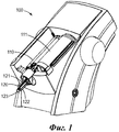
На Фиг.1 представлен вид в аксонометрии устройства для дозирования зубоврачебных материалов.Figure 1 presents a perspective view of a device for dispensing dental materials.
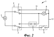
На Фиг.2 показана принципиальная схема блока управления устройством для дозирования зубоврачебных материалов в соответствии с одним из вариантов осуществления изобретения.Figure 2 shows a schematic diagram of a control unit for a device for dispensing dental materials in accordance with one embodiment of the invention.
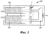
На Фиг.3 представлено схематическое изображение устройства для дозирования зубоврачебных материалов в соответствии с вариантом осуществления изобретения.Figure 3 presents a schematic illustration of a device for dispensing dental materials in accordance with an embodiment of the invention.
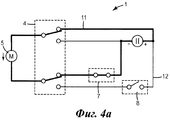
На Фиг.4а показана принципиальная схема блока управления, представленного на Фиг.2, на другом этапе работы в соответствии с вариантом осуществления изобретения.Fig. 4a shows a schematic diagram of the control unit shown in Fig. 2 at another stage of operation in accordance with an embodiment of the invention.
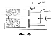
Фиг.4b иллюстрирует этап работы устройства, показанного на Фиг.3, который относится к этапу работы блока управления, показанному на Фиг.4а, в соответствии с вариантом осуществления изобретения.Fig. 4b illustrates an operation step of the device shown in Fig. 3, which relates to an operation step of a control unit shown in Fig. 4a, in accordance with an embodiment of the invention.
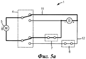
На Фиг.5а показана принципиальная схема блока управления, показанного на Фиг.4а, на дополнительном этапе работы в соответствии с вариантом осуществления изобретения.On figa shows a schematic diagram of the control unit shown in figa, at an additional stage of operation in accordance with an embodiment of the invention.
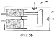
Фиг.5b иллюстрирует этап работы устройства, показанного на Фиг.4b, который относится к этапу работы блока управления, показанному на Фиг.5а, в соответствии с вариантом осуществления изобретения.Fig. 5b illustrates an operation step of the device shown in Fig. 4b, which relates to an operation step of the control unit shown in Fig. 5a, in accordance with an embodiment of the invention.
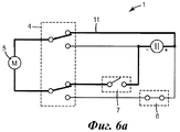
На Фиг.6а показана принципиальная схема блока управления, показанного на Фиг.5а, на дополнительном этапе работы в соответствии с вариантом осуществления изобретения.On figa shows a schematic diagram of the control unit shown in figa, at an additional stage of operation in accordance with an embodiment of the invention.
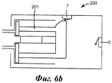
Фиг.6b иллюстрирует этап работы устройства, показанного на Фиг.5b, который относится к этапу работы блока управления, показанному на Фиг.6а, в соответствии с вариантом осуществления изобретения.Fig. 6b illustrates an operation step of the device shown in Fig. 5b, which relates to the operation step of the control unit shown in Fig. 6a, in accordance with an embodiment of the invention.
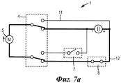
На Фиг.7а показана принципиальная схема блока управления, показанного на Фиг.6а, на дополнительном этапе работы в соответствии с вариантом осуществления изобретения.On figa shows a schematic diagram of the control unit shown in figa, at an additional stage of operation in accordance with an embodiment of the invention.
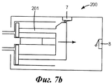
Фиг.7b иллюстрирует этап работы устройства, показанного на Фиг.6b, который относится к этапу работы блока управления, показанному на Фиг.7а, в соответствии с вариантом осуществления изобретения.FIG. 7b illustrates an operation step of the device shown in FIG. 6b, which relates to an operation step of a control unit shown in FIG. 7a, in accordance with an embodiment of the invention.
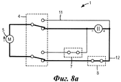
На Фиг.8а показана принципиальная схема блока управления, показанного на Фиг.7а, на дополнительном этапе работы в соответствии с вариантом осуществления изобретения.On figa shows a schematic diagram of the control unit shown in figa, at an additional stage of operation in accordance with an embodiment of the invention.
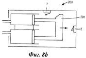
Фиг.8b иллюстрирует этап работы устройства, показанного на Фиг.7b, который относится к этапу работы блока управления, показанному на Фиг.8а, в соответствии с вариантом осуществления изобретения.Fig. 8b illustrates an operation step of the device shown in Fig. 7b, which relates to the operation step of the control unit shown in Fig. 8a, in accordance with an embodiment of the invention.
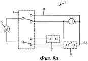
На Фиг.9а показана принципиальная схема блока управления, показанного на Фиг.8а, на дополнительном этапе работы в соответствии с вариантом осуществления изобретения.On figa shows a schematic diagram of the control unit shown in figa, at an additional stage of operation in accordance with an embodiment of the invention.
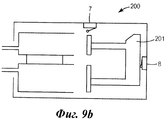
Фиг.9b иллюстрирует этап работы устройства, показанного на Фиг.8b, который относится к этапу работы блока управления, показанному на Фиг.9а, в соответствии с вариантом осуществления изобретения.Fig. 9b illustrates an operation step of the device shown in Fig. 8b, which relates to the operation step of the control unit shown in Fig. 9a, in accordance with an embodiment of the invention.
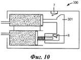
На Фиг.10 представлено схематическое изображение дозирующего устройства, показанного на Фиг.3, на другом этапе работы.Figure 10 presents a schematic representation of the metering device shown in Figure 3, at another stage of operation.
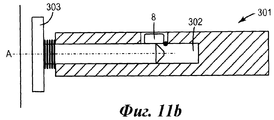
На Фиг.11а, Фиг.11b представлены детальные изображения толкателя на разных этапах работы дозирующего устройства в соответствии с вариантом осуществления изобретения.On figa, fig.11b presents a detailed image of the pusher at different stages of operation of the metering device in accordance with an embodiment of the invention.
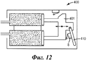
На Фиг.12 представлено схематическое изображение другого варианта выполнения устройства для дозирования зубоврачебного материала в соответствии с изобретением.12 is a schematic illustration of another embodiment of a device for dispensing dental material in accordance with the invention.
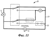
На Фиг.13 показана принципиальная схема блока управления устройством дозирования зубоврачебного материала в соответствии с другим вариантом осуществления изобретения.On Fig shows a schematic diagram of a control unit for a device for dispensing dental material in accordance with another embodiment of the invention.
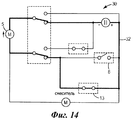
На Фиг.14 показана принципиальная схема блока управления устройством дозирования зубоврачебного материала в соответствии с дополнительным вариантом осуществления изобретения.On Fig shows a schematic diagram of a control unit for a device for dispensing dental material in accordance with a further embodiment of the invention.
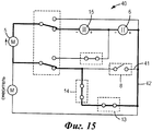
На Фиг.15 показана принципиальная схема блока управления устройством дозирования зубоврачебного материала в соответствии с еще одним вариантом осуществления изобретения.On Fig shows a schematic diagram of a control unit for a device for dispensing dental material in accordance with another embodiment of the invention.
ОСУЩЕСТВЛЕНИЕ ИЗОБРЕТЕНИЯDETAILED DESCRIPTION OF THE INVENTION
На Фиг.1 показано устройство 100 для смешивания и дозирования зубоврачебного материала. Устройство имеет привод и поэтому обеспечивает автоматическую дозированную подачу материала. Подобные устройства поставляет на рынок компания ЗМ ESPE AG (Германия) под торговой маркой 3М™ ESPE™ Pentamix™. Устройство 100 имеет два контейнера 110 и 111, в которых соответственно находятся два компонента зубоврачебного материала. Для перемешивания этих двух компонентов к устройству 100 присоединен смеситель 120. Смеситель 120 имеет камеру для смешивания, выполненную между вращающимся смесительным ротором 121 и корпусом 122 смесителя. Смеситель 120 соединен с контейнерами 110 и 111 так, что отдельные компоненты могут поступать в камеру для смешивания. Приготовленная смесь может выходить через выходное отверстие 123 смесителя 120. Устройство 100 выполнено с возможностью приводить в движение смесительный ротор 121, для перемешивания компонент в камере для смешнивания. Устройство 100 осуществляет непрерывный динамический процесс перемешивания, в течение которого компоненты могут непрерывно подаваться в камеру для смешивания, при этом полученная смесь может непрерывно выходить из смесителя. Таким образом, устройство позволяет приготавливать различное количество зубоврачебного материала, и при этом не требуется предварительного определения количества исходных компонентов смеси. Компоненты могут продвигаться к смесителю 120 с помощью толкателя (не показано) устройства 100. В устройстве 100 смеситель и толкатель могут быть приведены в действие одним двигателем или каждый своим двигателем. Соответственно, устройство 100 дополнительно имеет электрический источник питания двигателя или двигателей. В качестве источника питания могут быть использованы электрические батареи, электрические трансформаторы, согласующие устройства для внешнего источника питания.1 shows a
Представленное устройство может быть использовано, например, для смешивания и дозирования твердеющих зубоврачебных материалов. Полученным в результате смешивания материалом можно заполнить оттискную ложку и потом разместить ее во рту пациента для получения зубного слепка. Смеситель соединен с устройством 100 с возможностью съема. Поэтому, когда материал затвердевает и, следовательно, закупоривает смеситель, при следующем использовании устройства использованный смеситель может быть заменен другим, неиспользованным.The presented device can be used, for example, for mixing and dispensing hardening dental materials. The material obtained as a result of mixing can be used to fill an impression spoon and then place it in the patient's mouth to obtain a dental impression. The mixer is connected to the
На Фиг.2 показана принципиальная схема блока управления 1 устройством для дозирования в соответствии с изобретением. Блок управления 1 содержит первый двигатель 5 и источник питания 6 для снабжения электроэнергией двигателя 5. Первый двигатель 5 можно быть использован, например, для приведения в действие толкателя устройства. Кроме того, блок управления 1 содержит ключи для переключения режимов работы первого двигателя или его выключения. Ниже это будет разъяснено детально.Figure 2 shows a schematic diagram of a
Блок управления 1 содержит первый двухполюсный перекидной ключ 2 и второй двухполюсный перекидной ключ 3, образующие вместе двойной двухполюсный переключатель на два направления 4. Первый и второй двухполюсные перекидные ключи 2 и 3 обеспечивают попеременное подключение двигателя 5 к выводам противоположной полярности источника питания 6. Благодаря этому первый двигатель может осуществлять движения в противоположных направлениях, например продвигать вперед компоненты зубоврачебного материала или выполнять движение в обратную сторону от этих компонентов зубоврачебного материала. Двойной двухполюсный переключатель на два направления выполнен с возможностью совместного переключения первого и второго двухполюсных перекидных ключей. Специалисту понятно, что совместное переключение первого и второго двухполюсных перекидных ключей может происходить одновременно или последовательно, но двойной двухполюсный переключатель на два направления для этого активируют только один раз. Последовательное переключение может, например, обеспечить размыкание одной электрической цепи, прежде чем другая цепь не будет замкнута, этим предотвращается короткое замыкание во время их переключения.The
Блок управления 1 в показанной конфигурации содержит первую электрическую цепь 11 и вторую электрическую цепь 12, которые могут быть попеременно замкнуты с помощью первого и второго двухполюсных перекидных ключей 2, 3. В частности, первый и второй двухполюсные переключатели 2, 3 в блоке управления 1 предназначены для попеременного замыкания в одной из первой и второй электрических цепей 11 и 12, таким образом размыкая соединение в соответсвующей другой электрической цепи 11 или 12. Когда первый или второй двухполюсные переключатели 2, 3 размыкают цепь, прерывается подача от этой цепи питания на двигатель 5. Кроме того, по электрической цепи 11 или 12 первый двигатель 5 соединяется с полюсами противоположной полярности источника питания 6. Поэтому первый двигатель 5 меняет направление движения при питании от первой и второй цепей 11 и 12. Соответственно, блок управления 1 обеспечивает движения толкателя в противоположных направлениях для продвижения зубоврачебного материала или оттягивания толкателя назад в зависимости от положения переключателя.The
Блок управления 1 содержит также первый ключ 7 и второй ключ 8, в частности первый ключ 7 включен в первую электрическую цепь 11. Первый ключ 7 разрешает или запрещает функционирование первой электрической цепи 11, когда она выбрана соответствующим положением первого и второго двухполюсных ключей 2, 3. Второй ключ 8 является частью второй электрической цепи 12, поэтому он разрешает или запрещает ее функционирование, когда она выбрана соответствующим положением первого и второго двухполюсных ключей 2, 3. В показанном примере включена вторая электрическая цепь 12, и в результате первая электрическая цепь 11 выключена. Но при этом не замкнут второй ключ 8, так что вторая электрическая цепь 12 в целом оказалась разомкнутой. Следовательно, в ситуации, показанной на Фиг.2, двигатель 5 обесточен.The
На Фиг.3 показано размещение первого и второго ключей 7 и 8 в устройстве 200 для дозирования зубоврачебного материала. Устройство 200 имеет толкатель 201, выполненный с возможность перемещения внутри контейнеров 202, 203 для продвижения содержащихся в них компонентов материала к смесителю (не показан). В показанной ситуации толкатель 201 оттянут обратно от компонентов зубоврачебного материала и находится в своем заднем положении. Заднее положение в данном примере соответствует положению толкателя в заднем торце устройства. В этом положении толкателя 201 второй ключ 8 активирован. В приведенном примере второй ключ 8 выполнен в виде нормально замкнутого ключа, контакты которого замкнуты в неактивированном состоянии и разомкнуты при его активации. Специалисту понятно, что проиллюстрированный принцип может быть осуществлен различными путями, например с использованием нормально разомкнутого ключа, который устанавливают в устройство так, чтобы он оставался разомкнутым в положении толкателя в заднем торце устройства и активировался (замыкался) в противоположном случае.Figure 3 shows the placement of the first and
Предпочтительно, в качестве первого ключа 7 тоже использован ключ с нормально замкнутыми контактами. Тем не менее, специалист может заменить первый ключ 7 на нормально разомкнутый, если устройство будет соответствующим образом адаптировано для обеспечения точно такого же функционирования. В приведенном примере первый ключ 7 в заднем положении толкателя находится в неактивированном состоянии (ключ замкнут) и активирован (ключ разомкнут), если толкатель занимает переднее положение, обозначенное пунктирной линией. Переднее положение на чертеже соответствует положению толкателя в переднем торце устройства. Желательно, чтобы первый ключ 7 дополнительно находился в неактивированном состоянии между задним и передним положениями толкателя. Поэтому Фиг.3 отражает ситуацию, соответствующую Фиг.2, когда первый ключ 7 замкнут, а второй ключ 8 разомкнут, при этом с помощью переключателя выбрана вторая электрическая цепь. Таким образом, устройство 200, как показано на Фиг.4, может быть выключено и находиться в исходном состоянии.Preferably, a key with normally closed contacts is also used as the
Фиг.4а-9а иллюстрируют различные режимы работы блока управления 1, а Фиг.4b-9b иллюстрируют соответствующие этапы работы дозирующего устройства 200.Figs. 4a-9a illustrate various operating modes of the
На Фиг.4а переключателем 4 для работы выбрана первая электрическая цепь 11, при этом первый ключ 7 замкнут. Поэтому первый двигатель 5 получает электропитание по первой электрической цепи 11. Как показано на Фиг.4b (см. стрелку), первый двигатель 5 в режиме, обусловленном первой электрической цепью 11, заставляет толкатель 201 двигаться вперед по направлению к компонентам материала, что соответствует движению толкателя 201 вперед к его переднему положению. В показанной ситуации толкатель 201 все еще находится вблизи заднего положения, так что второй ключ 8 во второй электрической цепи 12 все еще разомкнут.On
С другой стороны, на Фиг.5а показано, что второй ключ 8 замкнут, потому что толкатель 201 продвинут к переднему положению, как показано на Фиг.5b. Как видно на Фиг.5а, переключателем 4 для работы все еще выбрана первая электрическая цепь 11, поэтому вторая электрическая цепь 12 разомкнута. При этом вторая электрическая цепь 12 разомкнута, несмотря на то что второй ключ 8 замкнут. Поскольку толкатель 201 (Фиг.5b) еще не достиг переднего положения, первый ключ 7 не активирован и, следовательно, замкнут. Соответственно, первая электрическая цепь 11 подает питание на двигатель 5, который заставляет толкатель 201 продвигаться дальше вперед. Однако, если бы переключатель 4 замкнул вторую электрическую схему 12, на первый двигатель 5 подавалось бы напряжение обратной полярности, и толкатель 201 двигался бы назад.On the other hand, FIG. 5a shows that the
На Фиг.6b показана ситуация, когда толкатель 201 устройства 200 оказался в переднем положении, и, следовательно, первый ключ 7 активирован и поэтому разомкнут. По этой причине, как показано на Фиг.6а, первая электрическая цепь 11 блока управления 1 разомкнута, и, соответственно, первый двигатель 5 выключен. Первый ключ 7 может быть выполнен в виде концевого выключателя, который предотвращает дальнейшее движение толкателя 201, например, когда пользователь продолжает удерживать переключатель 4 в положении дальнейшего дозирования материала, несмотря на то что толкатель 201 достиг положения в переднем торце устройства. Благодаря этому предотвращается повреждение устройства и/или первого двигателя 5, например из-за его перегрузки.6b shows a situation where the
На Фиг.7а показана ситуация, в которой переключатель 4 замкнул вторую электрическую цепь 12. Поскольку второй ключ 8 уже был замкнут, вторая электрическая цепь 12 теперь замкнута, поэтому на первый двигатель 5 подается питание. При этом первый двигатель 5 движется в направлении, противоположном тому, в котором он двигался, когда получал питание через первую электрическую цепь 11. Поэтому, как показано на Фиг.7b (см. стрелку), толкатель 201 двигается в обратном направлении от компонентов материала, т.е. он движется в направлении своего заднего положения.Fig. 7a shows a situation in which the
На Фиг.8b показано устройство 200, в котором толкатель 201 уже продвинулся в направлении своего заднего положения, по сравнению с положением, проиллюстрированным на Фиг.7b. При этом толкатель отодвинулся от первого ключа 7, поэтому ключ 7 замкнулся. Это, тем не менее, не изменило режима работы первого двигателя 5, поскольку первый ключ 7 является частью первой электрической цепи 11, которая в этот момент не работает.On fig.8b shows the
Фиг.9а и Фиг.9b соответствуют ситуации, показанной на Фиг.4а и 4b, но при этом переключатель 4 замыкает вторую электрическую цепь 12, например, в связи с тем, что он отжат.Figa and Fig.9b correspond to the situation shown in Figa and 4b, but the
Кроме того, переключатель 4 может иметь 3 различных положения, что обеспечивает возможностью одновременного размыкания обеих электрических цепей 11 и 12. В дальнейшем это положение переключателя, при котором размыкаются одновременно обе - первая и вторая электрические цепи, может быть исходной позицией переключателя, в которую он автоматически возвращается, если устройство не используется. Это позволяет автоматически останавливать устройство в любом положении толкателя во время дозирования материала или во время обратного хода толкателя, когда переключатель отжат.In addition, the
Предпочтительно, если переключатель 4 не задействован, он автоматически возвращается в исходную позицию, при которой замкнута вторая электрическая цепь, а для замыкания первой электрической цепи переключатель должен быть задействован. Поэтому желательно выполнить устройство таким образом, чтобы толкатель автоматически возвращался в свое заднее положение, когда переключатель отжат.Preferably, if
В показанном на Фиг.10 варианте осуществления изобретения второй ключ 8 установлен в устройстве 300 так, что заднее положение толкателя передвинуто на определенное расстояние позади переднего хода толкателя. Поэтому, когда движение толкателя вперед остановлено, толкатель может из его текущего положения автоматически вернуться не в абсолютное положение, а на упомянутое заранее заданное соответствующее расстояние. Иными словами толкатель не возвращается автоматически в положение в заднем торце устройства, но он может сдвинуться в обратном направлении только на заданное расстояние относительно положения, в котором толкателю был придан обратный ход. Поэтому, когда подача компонентов зубоврачебного материала прекращается, толкатели могут немного возвратиться назад, освобождая компоненты от давления, оказанного на них во время подачи. Этим может быть предотвращено остаточное течение компонентов после прекращения их подачи. Устройство 300 дополнительно содержит первый ключ 7, который активируется, когда толкатель достигает положения в переднем торце устройства.In the embodiment of FIG. 10, a
Толкатель 301, показанный на Фиг.10, более детально изображен на Фиг.11а и Фиг.11b. Толкатель 301 имеет гнездо 302 для размещения в нем поршня 303. Поршень 303 и толкатель 301 выполнены с возможностью передвижения относительно друг друга вдоль продольной оси А. По существу ось А соответствует направлению, в котором в устройстве 300 толкатель может продвигаться вперед или назад. В приведенном примере поршень 303 телескопически направляется в гнезде 302 толкателя 301. Вблизи заднего конца 304 поршня 303 второй ключ 8 установлен таким образом, что поршень 303 может активировать второй ключ 8 в зависимости от продольного положения поршня относительно толкателя. Поршень и толкатель направляются к исходному положению относительно друг друга с помощью пружины. В исходном положении поршня 303 относительно толкателя 301 второй ключ 8 отжат. Второй ключ 8 в данном примере является нормально разомкнутым, т.е. в отжатом состоянии он разомкнут. Исходное положение поршня и толкателя относительно друг друга может, например, соответствовать ситуации, при которой толкатель и поршень отодвинуты от компонентов материала. На Фиг.11b показано взаимное положение поршня и толкателя относительно друг друга, в котором толкатель толкает поршень вперед для выдавливания компонентов материала. На этом этапе поршень может оказаться так близко к толкателю, что второй ключ 8 активируется и замыкается. Когда второй ключ 8 замыкается, первый двигатель оказывается подсоединенным к источнику питания так, что он тянет толкатель назад. Как только толкатель отступает назад из позиции, показанной на Фиг.11b, поршень из-за воздействия пружины двигается в сторону от толкателя и при этом отжимает второй ключ 8 (см. Фиг.11а), вынуждая таким образом второй ключ 8 разомкнуться, и останавливает таким образом дальнейшее движение толкателя.The
На Фиг.12 показано устройство 400, представляющее собой альтернативный вариант осуществления изобретения, касающийся обратного хода толкателя в зависимости от переменной стартовой позиции. Устройство 400 имеет рычаг 410, шарнирно закрепленный на первом конце толкателя 401. Второй конец рычага 410 свободен и может, например, примыкать к продольной направляющей в устройстве. В преимущественном варианте осуществления изобретения рычаг 410 размещен в устройстве таким образом, что толкатель может тащить его за собой, при этом свободный конец рычага скользит вдоль направляющей, когда он перемещается вперед с толкателем, но при обратном движении он блокируется или прихватывается направляющей. Поэтому, когда толкатель движется назад, рычаг может двигаться ему навстречу. Второй ключ 8 может быть размещен, например, между толкателем 401 и рычагом 410, как показано. В этом случае второй ключ 8 может быть активирован во время обратного хода толкателя, при этом он находится в отжатом состоянии во время движения толкателя вперед. Таким образом, в устройстве 400 толкатель 401 может быть продвинут вперед в требуемое положение, однако он может быть остановлен вскоре после того, как он начнет обратное движение.12, an apparatus 400 is shown, which is an alternative embodiment of the invention regarding the return stroke of the pusher depending on the variable starting position. The device 400 has a
На Фиг.13 представлен блок управления 20, содержащий элементы блока управления 1, показанного на Фиг.2, но содержащий дополнительно второй двигатель 9. В первой электрической цепи 21 первый и второй двигатели соединены параллельно, а во второй электрической цепи 22 второй двигатель 9 зашунтирован накоротко. Второй двигатель 9 предпочтительно используется для приведения в действие смесителя для смешивания компонентов зубоврачебного материала. Таким образом, смеситель поддерживается в действии вместе с перемещением поршня, обеспечивающим доставку компонентов материала к смесителю, но когда толкатель возвращается, смеситель не работает. Поэтому оставшиеся компоненты материала не взбалтываются во время обратного хода толкателя, когда их подача в смеситель прерывается. Это предотвращает нежелательное интенсивное перемешивание и преждевременное отвердевание материала, вызывающее блокировку смесителя.On Fig presents a
На Фиг.14 представлен вариант блока управления 30, который содержит компоненты блока управления 20, показанного на Фиг.13, но имеет дополнительный третий ключ 13. Третий ключ 13 подсоединен параллельно ко второму ключу 8. Поэтому, когда второй ключ 8 разомкнут и выбрана вторая электрическая цепь 32, как показано, третий ключ может быть использован для шунтирования второго ключа и замыкания второй электрической цепи 32. Таким образом, первый двигатель 5 может быть включен для возврата толкателя, несмотря на то, что второй ключ 8 разомкнут. Такое решение обеспечивает возвращение толкателя назад в исходную позицию в вариантах, предусматривающих соотнесенный обратный ход. Это может способствовать, например, замене контейнеров в устройстве, потому что блок управления 30 допускает моторизованное возвращение толкателей, которое в иных случаях приходится выполнять вручную.On Fig presents a variant of the
На Фиг.15 показан еще один вариант блока управления 40, который содержит элементы блока управления 30, показанного на Фиг.14, но дополнительно к первому источнику питания 6 имеет второй источник питания 15, а также дополнительный четвертый ключ 14. Четвертый ключ 14 последовательно соединен с третьим ключом 13. Поэтому, если третий ключ 13 используется для возвращения толкателя, то четвертый ключ 14 может разомкнуть вторую электрическую цепь 42, как только толкатель достигает положения в заднем торце устройства. Таким образом, может быть предотвращено повреждение устройства, если пользователь продолжает использовать третий ключ 13 для возврата толкателя, несмотря на то, что толкатель уже достиг своего положения в заднем торце устройства. Второй источник питания 15 включен во вторую электрическую цепь 42 и последовательно соединен с первым источником питания 6. Поэтому напряжение во второй электрической цепи 42 увеличено, например, в два раза, так что двигатель 5, питающийся от второй электрической цепи 42, обычно работает на более высоких скоростях. Второй источник питания 15 не включен в первую электрическую цепь 41, так что в первой и второй электрических цепях 41, 42 двигатель работает на разных скоростях. Таким образом, толкатель может продвигаться в устройстве вперед на первой скорости и двигаться назад на второй скорости. Вторая скорость может быть больше, чем первая скорость, чтобы материал мог быть надлежащим образом дозирован и смешан, а толкатель мог быть быстро возвращен, например, для замены контейнеров в устройстве.On Fig shows another variant of the
Claims (14)
Applications Claiming Priority (3)
| Application Number | Priority Date | Filing Date | Title |
|---|---|---|---|
| GBGB0915008.7A GB0915008D0 (en) | 2009-08-28 | 2009-08-28 | Device for dispensing a dental material |
| GB0915008.7 | 2009-08-28 | ||
| PCT/US2010/046348 WO2011025737A1 (en) | 2009-08-28 | 2010-08-23 | Device for dispensing a dental material |
Publications (2)
| Publication Number | Publication Date |
|---|---|
| RU2012107808A RU2012107808A (en) | 2013-10-10 |
| RU2513110C2 true RU2513110C2 (en) | 2014-04-20 |
Family
ID=41172038
Family Applications (1)
| Application Number | Title | Priority Date | Filing Date |
|---|---|---|---|
| RU2012107808/14A RU2513110C2 (en) | 2009-08-28 | 2010-08-23 | Dental material dosed supply device |
Country Status (8)
| Country | Link |
|---|---|
| US (1) | US8613376B2 (en) |
| EP (1) | EP2470109A1 (en) |
| JP (1) | JP5746176B2 (en) |
| CN (1) | CN102481178B (en) |
| BR (1) | BR112012004215A2 (en) |
| GB (1) | GB0915008D0 (en) |
| RU (1) | RU2513110C2 (en) |
| WO (1) | WO2011025737A1 (en) |
Families Citing this family (8)
| Publication number | Priority date | Publication date | Assignee | Title |
|---|---|---|---|---|
| AU2011278055B2 (en) * | 2010-07-16 | 2015-04-02 | Mcgill Technology Limited | Dispensing apparatus |
| CN102568980B (en) * | 2012-02-15 | 2015-05-20 | 杭州鸿雁东贝光电科技有限公司 | Thermal-state lamp tube aging device with testing function |
| US20150022317A1 (en) * | 2013-07-17 | 2015-01-22 | GM Global Technology Operations LLC | Systems and methods for unlock with security mode |
| US10124303B2 (en) * | 2014-09-05 | 2018-11-13 | Nordson Corporation | Apparatus and methods for dispensing small beads of viscous material |
| JP6830439B2 (en) * | 2015-03-06 | 2021-02-17 | デンツプライ シロナ インコーポレイテッド | Dental material delivery system |
| JP2020508780A (en) * | 2017-03-01 | 2020-03-26 | デンツプライ シロナ インコーポレイテッド | Electric dispenser |
| CN114789125A (en) * | 2021-01-25 | 2022-07-26 | 南京泉峰科技有限公司 | Electric glue gun |
| JP2024048551A (en) * | 2022-09-28 | 2024-04-09 | 株式会社ジーシー | Impression material malaxation apparatus |
Citations (2)
| Publication number | Priority date | Publication date | Assignee | Title |
|---|---|---|---|---|
| US5341958A (en) * | 1992-12-24 | 1994-08-30 | Bayat John J | Power operated caulking tool |
| JP2007007641A (en) * | 2005-05-30 | 2007-01-18 | Koichi Gunji | Electric viscous material suction / discharge device and viscous material construction method using the same |
Family Cites Families (30)
| Publication number | Priority date | Publication date | Assignee | Title |
|---|---|---|---|---|
| US3764115A (en) * | 1971-06-30 | 1973-10-09 | Ibm | Method and apparatus for mixing fluids |
| CH562942A5 (en) * | 1972-06-08 | 1975-06-13 | Blieberger Rudolf | |
| US4181825A (en) | 1978-06-05 | 1980-01-01 | General Motors Corporation | Electric switch for motor reversing |
| US4180187A (en) * | 1978-06-30 | 1979-12-25 | Ben Haim Haim | Automatic piston drive mechanism for use in caulking gun |
| DE3327420A1 (en) * | 1983-07-29 | 1985-02-07 | Ludwig Schwerdtel GmbH, 8047 Karlsfeld | DOSING MACHINE FOR DOSING A MAIN DIMENSION AND AT LEAST ONE AGENT, ESPECIALLY FOR DOSING HIGH VISCOSITY MASSES |
| US4878601A (en) * | 1988-02-16 | 1989-11-07 | Flemming J Peter | Liquid dispenser |
| JP3053339U (en) * | 1997-08-18 | 1998-10-27 | 浩一 新井 | Auto dispenser for impression material |
| EP0956908A1 (en) * | 1998-05-15 | 1999-11-17 | Wilhelm A. Keller | Electrically driven dispensing apparatus for cartridges |
| DE29819661U1 (en) * | 1998-11-04 | 1999-02-25 | Kress-Elektrik GmbH & Co Elektromotorenfabrik, 72406 Bisingen | Device for squeezing and dispensing flowable multi-components |
| EP1010401B1 (en) | 1998-11-11 | 2003-02-05 | Ernst Mühlbauer GmbH & Co.KG | Method and device for obtaining a multicomponent mass, especially for dental purposes |
| DE29822967U1 (en) * | 1998-12-23 | 2000-05-11 | ESPE Dental AG, 82229 Seefeld | Device for spreading flowable masses |
| US7070318B2 (en) * | 2000-05-02 | 2006-07-04 | Renfro Charles K | Mixing apparatus having rotational and axial motion |
| JP3936837B2 (en) * | 2000-11-09 | 2007-06-27 | 株式会社モリタ製作所 | Dental filler and dental loader |
| US7116071B2 (en) * | 2000-12-06 | 2006-10-03 | Milwaukee Electric Tool Corporation | Power tool and motor controller |
| US6392373B1 (en) | 2000-12-06 | 2002-05-21 | Milwaukee Electric Tool Corporation | Automatic reverse motor controller |
| US6572259B2 (en) | 2001-04-20 | 2003-06-03 | Burnett Lime Co., Inc. | Apparatus and method to dispense a slurry |
| DE50110155D1 (en) * | 2001-07-26 | 2006-07-27 | Muehlbauer Ernst Gmbh & Co Kg | Method and device for producing a multicomponent mass |
| DE10164385C1 (en) * | 2001-12-28 | 2003-03-06 | Kettenbach Gmbh & Co Kg | Device for mixing two paste-like substances for dental work includes first channel extending through coupling section and having first and second parts with adjoining deflection section inbetween to ensure constant mixing ratio at outlet |
| US20040108334A1 (en) * | 2002-01-28 | 2004-06-10 | Strecker Timothy D. | Mixing rotary positive displacement pump for micro dispensing |
| US6889872B2 (en) * | 2002-06-28 | 2005-05-10 | Meritool, L.L.C. | Electric two-part material dispenser |
| DE202005005833U1 (en) * | 2005-02-25 | 2005-06-23 | Vosschemie Gmbh | Dispenser and mixer for two component reactive resin-fillers e.g. for repair of automobile bodywork |
| ATE438352T1 (en) * | 2005-06-03 | 2009-08-15 | 3M Innovative Properties Co | DENTAL MATERIAL PROCESSING SYSTEM AND COMMUNICATION METHOD |
| EP1834603A1 (en) | 2006-03-10 | 2007-09-19 | 3M Innovative Properties Company | Dispenser and method for dispensing dental material |
| GB0707573D0 (en) * | 2007-04-19 | 2007-05-30 | 3M Innovative Properties Co | Dispensing device with locking member |
| US20080267005A1 (en) * | 2007-04-24 | 2008-10-30 | Tyco Healthcare Group Lp | Applicator system and method of use |
| US7854348B2 (en) * | 2007-09-14 | 2010-12-21 | Jelley Pechnology Co., Ltd. | Device for dispensing a viscid material |
| GB0915002D0 (en) * | 2009-08-28 | 2009-09-30 | 3M Innovative Properties Co | Device for dispensing a dental material |
| GB0915007D0 (en) * | 2009-08-28 | 2009-09-30 | 3M Innovative Properties Co | Mixer and system for mixing and dispensing material |
| EP2324792A1 (en) * | 2009-11-20 | 2011-05-25 | 3M Innovative Properties Company | A device for dispensing a material |
| EP2324794A1 (en) * | 2009-11-20 | 2011-05-25 | 3M Innovative Properties Company | A device for dispensing a dental composition |
-
2009
- 2009-08-28 GB GBGB0915008.7A patent/GB0915008D0/en not_active Ceased
-
2010
- 2010-08-23 US US13/392,946 patent/US8613376B2/en not_active Expired - Fee Related
- 2010-08-23 EP EP10748196A patent/EP2470109A1/en not_active Withdrawn
- 2010-08-23 WO PCT/US2010/046348 patent/WO2011025737A1/en not_active Ceased
- 2010-08-23 CN CN201080038641.6A patent/CN102481178B/en not_active Expired - Fee Related
- 2010-08-23 RU RU2012107808/14A patent/RU2513110C2/en not_active IP Right Cessation
- 2010-08-23 JP JP2012526885A patent/JP5746176B2/en not_active Expired - Fee Related
- 2010-08-23 BR BR112012004215A patent/BR112012004215A2/en not_active IP Right Cessation
Patent Citations (2)
| Publication number | Priority date | Publication date | Assignee | Title |
|---|---|---|---|---|
| US5341958A (en) * | 1992-12-24 | 1994-08-30 | Bayat John J | Power operated caulking tool |
| JP2007007641A (en) * | 2005-05-30 | 2007-01-18 | Koichi Gunji | Electric viscous material suction / discharge device and viscous material construction method using the same |
Non-Patent Citations (3)
| Title |
|---|
| кол.2, линии 25-63. * |
| кол.5, линии 11-42, фиг.2. * |
| реферат, фиг.1, 7 . - " -. * |
Also Published As
| Publication number | Publication date |
|---|---|
| CN102481178B (en) | 2014-12-17 |
| GB0915008D0 (en) | 2009-09-30 |
| US8613376B2 (en) | 2013-12-24 |
| US20120231410A1 (en) | 2012-09-13 |
| EP2470109A1 (en) | 2012-07-04 |
| CN102481178A (en) | 2012-05-30 |
| BR112012004215A2 (en) | 2019-09-24 |
| RU2012107808A (en) | 2013-10-10 |
| JP2013502989A (en) | 2013-01-31 |
| WO2011025737A1 (en) | 2011-03-03 |
| JP5746176B2 (en) | 2015-07-08 |
Similar Documents
| Publication | Publication Date | Title |
|---|---|---|
| JP5746176B2 (en) | Device for dispensing dental materials | |
| RU2614685C2 (en) | Drive device of dosing mixing machine | |
| EP3572037B1 (en) | Oral irrigator | |
| AU2012358107B2 (en) | Driving device of a metering and mixing apparatus | |
| US8641669B2 (en) | Electromechanical injection apparatus | |
| US9381538B2 (en) | Driving device of a metering and mixing apparatus | |
| US8919617B2 (en) | Caulk gun with expansion drive | |
| CN101547659A (en) | Dispenser and method for dispensing dental material | |
| JP2015515359A5 (en) | ||
| CN103874521A (en) | Discharge device for media | |
| CN105688736A (en) | Handheld duplex mixing drive device, dosing apparatus and dosing method | |
| CA2973765C (en) | Dental material delivery system | |
| JP2000157562A (en) | Mouth washer | |
| JP2961192B2 (en) | Impression material mixing device | |
| CN220874383U (en) | Automatic oil dispenser for central needle of machine shell | |
| EP2497442B1 (en) | A device for mixing and dispensing a dental material | |
| JP2000084455A (en) | Extrusion equipment |
Legal Events
| Date | Code | Title | Description |
|---|---|---|---|
| MM4A | The patent is invalid due to non-payment of fees |
Effective date: 20180824 |