RU2524110C2 - Fast pyrolysis of biomass and hydrocarbon-bearing products and device to this end - Google Patents
Fast pyrolysis of biomass and hydrocarbon-bearing products and device to this end Download PDFInfo
- Publication number
- RU2524110C2 RU2524110C2 RU2012147357/05A RU2012147357A RU2524110C2 RU 2524110 C2 RU2524110 C2 RU 2524110C2 RU 2012147357/05 A RU2012147357/05 A RU 2012147357/05A RU 2012147357 A RU2012147357 A RU 2012147357A RU 2524110 C2 RU2524110 C2 RU 2524110C2
- Authority
- RU
- Russia
- Prior art keywords
- pyrolysis
- pyrolysis chamber
- heating elements
- heating
- walls
- Prior art date
Links
- 238000000197 pyrolysis Methods 0.000 title claims abstract description 118
- 229930195733 hydrocarbon Natural products 0.000 title claims description 12
- 239000002028 Biomass Substances 0.000 title claims description 11
- 239000004215 Carbon black (E152) Substances 0.000 title claims description 11
- 125000001183 hydrocarbyl group Chemical group 0.000 title description 2
- 238000000034 method Methods 0.000 claims abstract description 45
- 239000000047 product Substances 0.000 claims abstract description 38
- 239000000446 fuel Substances 0.000 claims abstract description 16
- 238000009833 condensation Methods 0.000 claims abstract description 11
- 230000005494 condensation Effects 0.000 claims abstract description 11
- 239000012265 solid product Substances 0.000 claims abstract description 8
- 239000012263 liquid product Substances 0.000 claims abstract description 6
- 238000010438 heat treatment Methods 0.000 claims description 86
- 239000000203 mixture Substances 0.000 claims description 46
- 239000002994 raw material Substances 0.000 claims description 35
- 238000011068 loading method Methods 0.000 claims description 13
- 150000002430 hydrocarbons Chemical class 0.000 claims description 10
- 239000003990 capacitor Substances 0.000 claims description 7
- 230000009471 action Effects 0.000 claims description 4
- 238000004140 cleaning Methods 0.000 claims description 4
- 239000004020 conductor Substances 0.000 claims description 4
- 230000007797 corrosion Effects 0.000 claims description 4
- 238000005260 corrosion Methods 0.000 claims description 4
- 229910001120 nichrome Inorganic materials 0.000 claims description 4
- 238000001816 cooling Methods 0.000 claims description 3
- 239000003779 heat-resistant material Substances 0.000 claims description 2
- 239000011150 reinforced concrete Substances 0.000 claims description 2
- 239000000126 substance Substances 0.000 abstract description 12
- 239000007787 solid Substances 0.000 abstract description 7
- 239000002699 waste material Substances 0.000 abstract description 5
- 238000000926 separation method Methods 0.000 abstract description 4
- 239000010791 domestic waste Substances 0.000 abstract description 3
- 238000012271 agricultural production Methods 0.000 abstract description 2
- 238000011065 in-situ storage Methods 0.000 abstract 1
- 238000010327 methods by industry Methods 0.000 abstract 1
- 239000007789 gas Substances 0.000 description 19
- 239000007788 liquid Substances 0.000 description 18
- 238000012545 processing Methods 0.000 description 16
- 230000008569 process Effects 0.000 description 14
- 239000012634 fragment Substances 0.000 description 13
- 239000000463 material Substances 0.000 description 7
- 238000013461 design Methods 0.000 description 6
- 238000010586 diagram Methods 0.000 description 6
- 239000006185 dispersion Substances 0.000 description 6
- 238000009434 installation Methods 0.000 description 5
- 238000001035 drying Methods 0.000 description 4
- 238000000227 grinding Methods 0.000 description 4
- 238000006243 chemical reaction Methods 0.000 description 3
- 239000003245 coal Substances 0.000 description 3
- 238000000354 decomposition reaction Methods 0.000 description 3
- 238000011049 filling Methods 0.000 description 3
- 238000004519 manufacturing process Methods 0.000 description 3
- QVGXLLKOCUKJST-UHFFFAOYSA-N atomic oxygen Chemical compound [O] QVGXLLKOCUKJST-UHFFFAOYSA-N 0.000 description 2
- 230000015572 biosynthetic process Effects 0.000 description 2
- 230000006378 damage Effects 0.000 description 2
- 230000007423 decrease Effects 0.000 description 2
- 238000005265 energy consumption Methods 0.000 description 2
- 238000005516 engineering process Methods 0.000 description 2
- 239000002440 industrial waste Substances 0.000 description 2
- 229910052500 inorganic mineral Inorganic materials 0.000 description 2
- 238000012423 maintenance Methods 0.000 description 2
- 239000002184 metal Substances 0.000 description 2
- 239000011707 mineral Substances 0.000 description 2
- 239000010813 municipal solid waste Substances 0.000 description 2
- 229910052760 oxygen Inorganic materials 0.000 description 2
- 239000001301 oxygen Substances 0.000 description 2
- 239000002245 particle Substances 0.000 description 2
- 239000003415 peat Substances 0.000 description 2
- 230000035699 permeability Effects 0.000 description 2
- 239000003507 refrigerant Substances 0.000 description 2
- 230000008439 repair process Effects 0.000 description 2
- 238000010517 secondary reaction Methods 0.000 description 2
- 238000012360 testing method Methods 0.000 description 2
- 239000002023 wood Substances 0.000 description 2
- OKTJSMMVPCPJKN-UHFFFAOYSA-N Carbon Chemical compound [C] OKTJSMMVPCPJKN-UHFFFAOYSA-N 0.000 description 1
- UGFAIRIUMAVXCW-UHFFFAOYSA-N Carbon monoxide Chemical compound [O+]#[C-] UGFAIRIUMAVXCW-UHFFFAOYSA-N 0.000 description 1
- 208000005156 Dehydration Diseases 0.000 description 1
- 229910000737 Duralumin Inorganic materials 0.000 description 1
- 230000002411 adverse Effects 0.000 description 1
- 239000002154 agricultural waste Substances 0.000 description 1
- 239000002956 ash Substances 0.000 description 1
- 239000012075 bio-oil Substances 0.000 description 1
- 229910052799 carbon Inorganic materials 0.000 description 1
- 239000000919 ceramic Substances 0.000 description 1
- 239000003795 chemical substances by application Substances 0.000 description 1
- 230000005495 cold plasma Effects 0.000 description 1
- 150000001875 compounds Chemical class 0.000 description 1
- 238000011109 contamination Methods 0.000 description 1
- 230000018044 dehydration Effects 0.000 description 1
- 238000006297 dehydration reaction Methods 0.000 description 1
- 230000006866 deterioration Effects 0.000 description 1
- 238000004880 explosion Methods 0.000 description 1
- 238000000605 extraction Methods 0.000 description 1
- 239000003546 flue gas Substances 0.000 description 1
- 238000005338 heat storage Methods 0.000 description 1
- 239000003077 lignite Substances 0.000 description 1
- 230000007246 mechanism Effects 0.000 description 1
- 239000005416 organic matter Substances 0.000 description 1
- 238000005192 partition Methods 0.000 description 1
- 230000035515 penetration Effects 0.000 description 1
- 238000004157 plasmatron Methods 0.000 description 1
- 239000004033 plastic Substances 0.000 description 1
- 238000004064 recycling Methods 0.000 description 1
- 230000000717 retained effect Effects 0.000 description 1
- 238000005245 sintering Methods 0.000 description 1
- 239000010802 sludge Substances 0.000 description 1
- 239000004449 solid propellant Substances 0.000 description 1
- 239000002910 solid waste Substances 0.000 description 1
- 238000012546 transfer Methods 0.000 description 1
- 230000007704 transition Effects 0.000 description 1
- XLYOFNOQVPJJNP-UHFFFAOYSA-N water Substances O XLYOFNOQVPJJNP-UHFFFAOYSA-N 0.000 description 1
- 239000002916 wood waste Substances 0.000 description 1
Images
Landscapes
- Processing Of Solid Wastes (AREA)
Abstract
Description
Изобретения относятся к способам и устройствам для осуществления быстрого пиролиза неизмельченных биомасс и углеводородсодержащих смесей и могут быть использованы для утилизации твердых бытовых и промышленных отходов, отходов деревообработки, сельскохозяйственного и пищевого производства, а также для переработки твердых низкокалорийных продуктов и смесей, содержащих органическую составляющую (гудрон, сланцы, высокозольный и бурый уголь, торф, шламы и др.), с получением топливных продуктов и химикатов.The invention relates to methods and devices for the rapid pyrolysis of unmilled biomass and hydrocarbon-containing mixtures and can be used for the disposal of solid household and industrial wastes, woodworking waste, agricultural and food production, as well as for the processing of solid low-calorie products and mixtures containing an organic component (tar , shale, high-ash and brown coal, peat, sludge, etc.), with the receipt of fuel products and chemicals.
К технологиям быстрого пиролиза, имеющих целью образование максимального количества жидких продуктов, относят процессы термохимического разложения углеводородсодержащих веществ без доступа кислорода в условиях быстрого нагрева до температуры, близкой к 500°С, и времени пребывания образовавшихся парогазовых продуктов при температуре 400-500°С менее 2 с. Эти условия требуют предварительного измельчения исходного сырья до частиц размером менее 3 мм [Thermochemical Conversion of Biomass to Liquid Fuels and Chemicals, Edited by M. Crocer, USA, Royal Society of Chemistry 2010, p.150]. Последнее требование увеличивает энергозатраты и стоимость реализации процесса и осложняет создание мобильных пиролитических установок, целесообразность использования которых обусловлена высокими расходами по сбору и перемещению исходного сырья с низкой энергетической и массовой плотностью к месту его переработки.The fast pyrolysis technologies aimed at the formation of the maximum amount of liquid products include the processes of thermochemical decomposition of hydrocarbon-containing substances without oxygen in conditions of rapid heating to a temperature close to 500 ° C, and the residence time of the resulting vapor-gas products at a temperature of 400-500 ° C less than 2 from. These conditions require preliminary grinding of the feedstock to particles smaller than 3 mm [Thermochemical Conversion of Biomass to Liquid Fuels and Chemicals, Edited by M. Crocer, USA, Royal Society of Chemistry 2010, p.150]. The latter requirement increases the energy consumption and the cost of implementing the process and complicates the creation of mobile pyrolytic plants, the feasibility of using which is due to the high costs of collecting and moving the feedstock with low energy and mass density to the place of its processing.
Описаны варианты способа переработки углеродсодержащих твердых веществ в альтернативное топливо методом быстрого пиролиза [RU 2451880 C2, опубл. 27.05.2012]. Способ осуществляют в две стадии, при этом на первой стадии сырье обезвоживают в вибрационной сушильной камере с кипящим слоем при температуре 155-170°С, а затем в реакторе быстрого пиролиза сырье подвергают термической деструкции по механизму т.н. энтропийного взрыва при температурах в интервале от 520°С (для древесных отходов) до 950°С (для углей и отходов угледобычи, ТБО и отходов сельскохозяйственного производства). Время пиролиза 5 с. Для осуществления процесса сырье предварительно измельчают до размера частиц от 0,1 до 5,0 мм в зависимости от вида сырья. Описанные варианты характеризуются следующими общими недостатками: необходимость предварительного измельчения сырья и технологическое разделение процессов сушки и пиролиза, требующее использования отдельных устройств различного типа.Variants of a method for processing carbon-containing solids into alternative fuel by the rapid pyrolysis method are described [RU 2451880 C2, publ. 05/27/2012]. The method is carried out in two stages, while in the first stage, the raw materials are dehydrated in a vibrating fluidized bed drying chamber at a temperature of 155-170 ° C, and then in the fast pyrolysis reactor the raw materials are subjected to thermal destruction by the so-called mechanism. entropy explosion at temperatures ranging from 520 ° C (for wood waste) to 950 ° C (for coal and coal waste, solid waste and agricultural waste). Pyrolysis time 5 s. To implement the process, the raw materials are pre-crushed to a particle size of from 0.1 to 5.0 mm, depending on the type of raw material. The described options are characterized by the following general disadvantages: the need for preliminary grinding of raw materials and the technological separation of drying and pyrolysis processes, which require the use of separate devices of various types.
Известен способ переработки органических веществ [RU 2201951 C1, опубл. 10.04.2003], согласно которому нагрев перерабатываемой смеси в газовой среде или в вакууме выполняют постадийно путем высокоскоростного нагрева со скоростью 103-105 град/с до температуры, которая для каждой стадии различна: от 200-375°С на первой стадии обезвоживания до 550-750°С на стадии, собственно, пиролиза, при этом на каждой стадии выделяют различные компоненты. Постадийный высокоскоростной нагрев обеспечивают последовательной подачей перерабатываемой смеси на вращающиеся валки, нагретые до температуры, соответствующей данной стадии. Необходимость нагрева массивных валков, которые нагревают лишь прилежащие слои прижатой к ним перерабатываемой смеси, исключает использование данного способа в промышленном масштабе. Кроме того, громоздкость системы последовательно расположенных валков затрудняет создание мобильных пиролитических установок для реализации способа.A known method of processing organic substances [RU 2201951 C1, publ. 04/10/2003], according to which the mixture to be heated in a gas medium or in vacuum is performed in stages by high-speed heating at a rate of 10 3 -10 5 deg / s to a temperature that is different for each stage: from 200-375 ° C in the first stage of dehydration up to 550-750 ° С at the stage of pyrolysis, in fact, various components are distinguished at each stage. Stage-by-stage high-speed heating is ensured by sequential supply of the processed mixture to the rotating rolls heated to a temperature corresponding to this stage. The need to heat massive rolls that heat only the adjacent layers of the processed mixture pressed to them, eliminates the use of this method on an industrial scale. In addition, the cumbersome system of sequentially located rolls makes it difficult to create mobile pyrolytic plants for implementing the method.
Известен способ переработки влагосодержащего органического вещества в жидкое и газообразное топливо [RU 2203922 C1, опубл. 10.05.2003] путем измельчения и нагрева мелкодисперстного органического вещества без доступа кислорода в двух разделенных камерах: до 250-375°С (сушка) и до 650-750°С (переработка). При этом во второй камере обезвоженное мелкодисперсное вещество нагревают под действием холодно-плазменного высокочастотного разряда реактивного тока напряжением 1-500 кВ, частотой 1-300 кГц. Температура нагрева 650-750°С, мощность 0,8-1,2 кВт на каждый грамм перерабатываемого за 1 с вещества. В числе недостатков способа - необходимость предварительного измельчения сырья и существенное превышение температуры нагрева сырья, требуемой для максимального выхода жидкой фракции. Кроме того, технологическое разделение процессов сушки и пиролиза требует использования устройств, снабженных нагревателями различного типа, что усложняет и удорожает изготовление устройства.A known method of processing a moisture-containing organic substance into liquid and gaseous fuels [RU 2203922 C1, publ. 05/10/2003] by grinding and heating finely dispersed organic matter without oxygen in two separate chambers: up to 250-375 ° C (drying) and up to 650-750 ° C (processing). Moreover, in the second chamber, the dehydrated fine substance is heated under the influence of a cold-plasma high-frequency discharge of a reactive current with a voltage of 1-500 kV, frequency 1-300 kHz. The heating temperature is 650-750 ° C, the power is 0.8-1.2 kW per gram of material processed in 1 s. Among the disadvantages of the method is the need for preliminary grinding of raw materials and a significant excess of the heating temperature of the raw materials required for maximum yield of the liquid fraction. In addition, the technological separation of drying and pyrolysis processes requires the use of devices equipped with heaters of various types, which complicates and increases the cost of manufacturing the device.
Известны способ и установка для переработки органического и минерального сырья в жидкое и газообразное топливо [RU 2349624 C1, опубл. 20.03.2009], предназначенные для быстрого пиролиза различных видов органического и минерального сырья. Пиролиз предварительно измельченного и высушенного сырья, размещенного на движущемся конвейере в герметичном реакторе, осуществляют с помощью установленного над конвейером одноэлектродного плазмотрона путем быстрого нагрева сырья в плазме высокочастотного разряда с температурой 500-1500°С и затратах энергии 0,2-0,6 кВт/ч на 1 кг сырья при скорости обработки 0,1-10 тонн сырья в час. При этом плазмотрон совмещает функции устройства получения плазмы высокочастотного разряда и устройства высокоскоростного нагрева сырья. Установка может быть использована как в стационарном режиме, так и в мобильном варианте с использованием автономного источника энергии. В описании не приведены сведения о требуемой степени дисперсности сырья, однако очевидно, что при однократном проходе относительно крупные фрагменты при использовании данного способа и устройства могут быть не переработаны, а рециркуляция в данном устройстве не предусмотрена, что накладывает жесткие требования в отношении дисперсности перерабатываемой смеси. Указанный диапазон температуры нагрева сырья также существенно превышает уровень, требуемый для максимального выхода жидкой фракции, что значительно снижает ее долю в продуктах пиролиза. То же следует сказать и в отношении времени пребывания парогазовой смеси при высокой температуре. Кроме того, нагрев сырья осуществляют в тонком слое на холодном конвейере, что препятствует нагреву прилегающей к нему части смеси, вследствие чего определенная часть смеси также окажется не переработанной. Необходимо также отметить, что стенки реактора в процессе переработки сырья остаются холодными, что приводит к конденсации на них парогазовой смеси, к неконтролируемым потерям и загрязнению установки.A known method and installation for processing organic and mineral raw materials into liquid and gaseous fuels [RU 2349624 C1, publ. 03/20/2009], intended for rapid pyrolysis of various types of organic and mineral raw materials. The pyrolysis of pre-ground and dried raw materials placed on a moving conveyor in an airtight reactor is carried out using a single-electrode plasmatron installed above the conveyor by quickly heating the raw materials in a high-frequency discharge plasma with a temperature of 500-1500 ° C and energy costs of 0.2-0.6 kW / h per 1 kg of raw materials at a processing speed of 0.1-10 tons of raw materials per hour. In this case, the plasma torch combines the functions of a device for producing a high-frequency discharge plasma and a device for high-speed heating of raw materials. The installation can be used both in stationary mode and in the mobile version using an autonomous energy source. The description does not provide information about the required degree of dispersion of the raw materials, however, it is obvious that with a single pass, relatively large fragments using this method and device may not be processed, and recycling in this device is not provided, which imposes strict requirements on the dispersion of the processed mixture. The specified temperature range of the heating of raw materials also significantly exceeds the level required for maximum yield of the liquid fraction, which significantly reduces its share in the pyrolysis products. The same should be said with respect to the residence time of the gas-vapor mixture at high temperature. In addition, the heating of the raw materials is carried out in a thin layer on a cold conveyor, which prevents heating of the adjacent part of the mixture, as a result of which a certain part of the mixture will also not be processed. It should also be noted that the walls of the reactor during the processing of raw materials remain cold, which leads to condensation of the vapor-gas mixture on them, to uncontrolled losses and contamination of the installation.
Описан газификатор твердого топлива, предназначенный для переработки торфа, низкосортного угля, отходов деревообработки, твердых бытовых отходов и т.п. путем взаимодействия топлива с газифицирующим агентом и пиролиза с получением горючего продукт-газа [RU 2232347 C2, опубл. 10.07.2004]. С целью повышения эффективности переработки продуктов, имеющих неравномерно распределенную по объему насыпную плотность, или склонных к спеканию под воздействием высоких температур, внутренние секции устройства, выполненные с возможностью вращения вокруг вертикальной оси устройства, имеют кожух с расположенной в нем футеровкой, в котором закреплены концы термоаккумулирующих элементов, представляющих собой керамические стержни, обладающие высокой теплоемкостью, равномерно распределенные по объему внутренних полостей секций диаметрально один над другим, или под углом друг к другу, или в виде объемной решетки, где элементы одного ряда находятся под углом к элементам другого ряда. Образовавшиеся спеки и уплотнения, соприкасаясь с горячими термоаккумулирующими элементами, интенсивно нагреваются и в процессе вращения секций разрушаются, что способствует улучшению газопроницаемости и теплообмена в спеках и уплотнениях, ускорению процесса пиролиза и повышению производительности газификатора. Однако это устройство не пригодно для осуществления технологии быстрого пиролиза, и, кроме того, запаса тепловой энергии, аккумулированной в стержнях, недостаточно для разрушения и пиролиза крупных фрагментов, которые могут содержаться в перерабатываемом сырье.A solid fuel gasifier is described for processing peat, low-grade coal, woodworking waste, municipal solid waste, etc. by reacting fuel with a gasifying agent and pyrolysis to obtain a combustible product gas [RU 2232347 C2, publ. 07/10/2004]. In order to increase the efficiency of processing products with a bulk density unevenly distributed over the volume, or prone to sintering under the influence of high temperatures, the internal sections of the device, which are rotatable around the vertical axis of the device, have a casing with a lining located in it, in which the ends of the heat storage elements representing ceramic rods having high heat capacity, uniformly distributed over the volume of internal cavities of diameter sections one above the other, or at an angle to each other, or in the form of a volumetric lattice, where the elements of one row are at an angle to the elements of the other row. The resulting specs and seals, in contact with hot thermo-accumulating elements, are heated intensively and are destroyed during the rotation of the sections, which helps to improve gas permeability and heat transfer in the cakes and seals, accelerate the pyrolysis process and increase the performance of the gasifier. However, this device is not suitable for the implementation of rapid pyrolysis technology, and, in addition, the supply of thermal energy accumulated in the rods is not enough for the destruction and pyrolysis of large fragments that may be contained in the processed raw materials.
Известны устройства, в которых повышение эффективности пиролиза достигается за счет использования нагревательных элементов, расположенных внутри пиролизной камеры, при этом внутренние источники тепла используются самостоятельно или в сочетании с внешними.Known devices in which an increase in the efficiency of pyrolysis is achieved through the use of heating elements located inside the pyrolysis chamber, while the internal heat sources are used independently or in combination with external ones.
В качестве прототипа заявляемых способа и устройства для его осуществления выбраны способ и устройство для термохимической обработки материалов растительного происхождения, описанные в [RU 2039078 C1, опубл. 09.07.1995]. Способ включает загрузку материала, нагрев его в герметичной камере до 400-450°С, при этом нагрев через стенку камеры осуществляют одновременно с постоянным равномерным нагревом внутри обрабатываемой массы продолжительностью 5-7 ч. Для осуществления способа предложено устройство, снабженное топкой для сжигания топлива и вытяжной трубой, включающее металлическую герметичную камеру, расположенную внутри теплоизоляционного слоя с зазором между ними, причем камера внутри снабжена равномерно расположенными нагревателями, а снаружи перегородками, плотно прилегающими к наружной поверхности камеры и внутренней поверхности теплоизоляционного слоя, в перегородках выполнены сквозные отверстия. Нагреватели представляют собой трубы, по которым пропускают часть потока дымовых газов из топки, разбивающие слой обрабатываемого материала на слои меньших размеров, при этом подача от этих элементов теплового потока, встречного греющей стенке, приводит к более быстрому нагреву более тонких слоев загруженного материала. Процесс характеризуется высокой продолжительностью, что делает нецелесообразным его промышленное использование и существенно снижает выход жидких фракций, а его конструктивные особенности не позволяет осуществлять эффективный пиролиз неизмельченных материалов, включающих крупные фрагменты.As a prototype of the claimed method and device for its implementation, a method and a device for thermochemical processing of materials of plant origin, described in [RU 2039078 C1, publ. 07/09/1995]. The method includes loading the material, heating it in a sealed chamber to 400-450 ° C, while heating through the chamber wall is carried out simultaneously with constant uniform heating inside the treated mass for a duration of 5-7 hours. A device equipped with a furnace for burning fuel is proposed for implementing the method exhaust pipe, including a metal sealed chamber located inside the heat-insulating layer with a gap between them, and the chamber inside is equipped with evenly spaced heaters, and outside Kami, tightly surrounding the outer surface of the chamber and the inner surface of the heat-insulating layer in the partitions through holes. Heaters are pipes through which part of the flue gas stream from the furnace is passed, breaking the layer of the processed material into smaller layers, while the supply of heat flow from these elements counter to the heating wall leads to faster heating of thinner layers of the loaded material. The process is characterized by a high duration, which makes its industrial use impractical and significantly reduces the yield of liquid fractions, and its design features do not allow efficient pyrolysis of unmilled materials, including large fragments.
Важным фактором, влияющим на выход наиболее ценной жидкой фракции, является время пребывания парогазовых продуктов пиролиза в условиях высокой температуры [Е. Hoekstra, Fast pyrolysis ofbiomass 3, Ph.D. Thesis, University of Twente, Enschede, The Netherlands, 2011]. Быстрое удаление продуктов пиролиза из зоны реакции минимизирует протекание вторичных реакций, приводящих к уменьшению выхода и ухудшению химического состава жидкой фракции.An important factor affecting the yield of the most valuable liquid fraction is the residence time of gas-vapor pyrolysis products at high temperatures [E. Hoekstra, Fast pyrolysis ofbiomass 3, Ph.D. Thesis, University of Twente, Enschede, The Netherlands, 2011]. The rapid removal of pyrolysis products from the reaction zone minimizes the occurrence of secondary reactions leading to a decrease in yield and a deterioration in the chemical composition of the liquid fraction.
Задачей, на решение которой направлена заявляемая группа изобретений, является создание способа быстрого пиролиза биомассы и углеводородсодержащих продуктов и устройства для его осуществления, позволяющих проводить быстрый пиролиз неизмельченного сырья, содержащего, в том числе, и крупные фрагменты. Дополнительно заявляемое изобретение решает задачу минимизации времени пребывания первичных парогазовых продуктов пиролиза при высокой температуре, их максимально быструю конденсацию и создание, таким образом, условий, обеспечивающих максимальный выход жидкой фракции, обладающей наибольшей энергетической ценностью и содержащей большое количество химических соединений, имеющих самостоятельное прикладное значение.The problem to which the claimed group of inventions is directed is to create a method for the rapid pyrolysis of biomass and hydrocarbon-containing products and a device for its implementation, allowing for fast pyrolysis of unmilled raw materials, including large fragments. Additionally, the claimed invention solves the problem of minimizing the residence time of primary combined-cycle pyrolysis products at high temperature, their maximum condensation and the creation, therefore, of conditions that ensure maximum yield of a liquid fraction having the highest energy value and containing a large number of chemical compounds that have independent applied value.
Поставленная задача решается предлагаемым способом быстрого пиролиза биомассы и углеводородсодержащих продуктов, включающим загрузку сырья в пиролизную камеру, пиролиз с помощью расположенных внутри пиролизной камеры нагревательных элементов, выход полученной парогазовой смеси и выгрузку полученного твердого продукта, отличающийся тем, что пиролиз осуществляют под действием последовательности тепловых импульсов, передаваемых от нагреваемых электрическими импульсами нагревательных элементов, размещенных в пиролизной камере таким образом, что ее объем разделен на локально нагреваемые ячейки, при этом для электропитания нагревательных элементов используют источник тока с электронным переключателем, причем длительность электрического импульса составляет 0,1-1,0 с, мощность электрического импульса выбирают такой, чтобы в течение импульса обеспечить нагрев нагревательного элемента до температуры 450-500°С, временной интервал между электрическими импульсами выбирают таким, чтобы обеспечить возможность остывания нагревательного элемента в промежутках между импульсами до температуры 200-250°С, при этом выход полученной парогазовой смеси осуществляется через отверстия в стенках пиролизной камеры, а конденсация ее паровой фракции осуществляется на конденсаторах, представляющих собой охлаждаемые поверхности, расположенные на минимально возможном расстоянии от внешних стенок пиролизной камеры.The problem is solved by the proposed method for the rapid pyrolysis of biomass and hydrocarbon-containing products, including loading raw materials into the pyrolysis chamber, pyrolysis using heating elements located inside the pyrolysis chamber, outputting the obtained vapor-gas mixture and unloading the obtained solid product, characterized in that the pyrolysis is carried out under the action of a sequence of thermal pulses transmitted from electric elements heated by electric pulses placed in the pyrolysis chamber so so that its volume is divided into locally heated cells, while a current source with an electronic switch is used to power the heating elements, and the duration of the electric pulse is 0.1-1.0 s, the power of the electric pulse is chosen so as to ensure during the pulse heating the heating element to a temperature of 450-500 ° C, the time interval between the electrical pulses is chosen so as to allow cooling of the heating element in the intervals between the pulse E to a temperature of 200-250 ° C, the yield of the resulting gas mixture through openings in the walls of the pyrolysis chamber and condensation of its vapor fraction is performed on the capacitors, which are cooled surfaces arranged at the smallest possible distance from the outer walls of the pyrolysis chamber.
Поставленная задача решается также предлагаемым устройством, содержащим загрузочную емкость, пиролизную камеру, емкости для приема жидких и твердых продуктов и размещенные внутри пиролизной камеры нагревательные элементы, отличающееся тем, что нагревательные элементы размещены в объеме пиролизной камеры таким образом, что ее объем разделен на локально нагреваемые ячейки, при этом нагревательные элементы выполнены из коррозионно- и термостойкого токопроводящего материала с высоким удельным электрическим сопротивлением и подсоединены к источнику тока с электронным переключателем, боковые стенки пиролизной камеры имеют отверстия для выхода полученной при пиролизе парогазовой смеси, а снаружи пиролизной камеры на минимально возможном расстоянии от ее стенок расположены конденсаторы, представляющие собой охлаждаемые поверхности.The problem is also solved by the proposed device containing a loading container, a pyrolysis chamber, containers for receiving liquid and solid products and heating elements placed inside the pyrolysis chamber, characterized in that the heating elements are placed in the volume of the pyrolysis chamber in such a way that its volume is divided into locally heated cells, while the heating elements are made of corrosion-resistant and heat-resistant conductive material with high electrical resistivity and are connected They are connected to a current source with an electronic switch, the side walls of the pyrolysis chamber have openings for the outlet of the vapor-gas mixture obtained by pyrolysis, and capacitors representing cooled surfaces are located outside the pyrolysis chamber at the minimum possible distance from its walls.
Заявляемым способом могут быть переработаны биомассы, включая продукты деревообработки, в том числе, содержащие крупные фрагменты, отходы пищевой промышленности и сельскохозяйственного производства, твердые бытовые и промышленные отходы, а также твердые углеводородсодержащие продукты и смеси, имеющие низкую энергетическую ценность, например сланцы, илы, гудрон и др.The inventive method can be processed biomass, including wood products, including those containing large fragments, waste from the food industry and agricultural production, solid household and industrial waste, as well as solid hydrocarbon-containing products and mixtures of low energy value, such as shale, silt, tar, etc.
Наличие в перерабатываемой смеси металлических фрагментов, габариты которых превышают минимальный размер ячеек пиролизной камеры, не допускается.The presence in the processed mixture of metal fragments whose dimensions exceed the minimum cell size of the pyrolysis chamber is not allowed.
Способ осуществляют следующим образом.The method is as follows.
Из загрузочной емкости, которая одновременно выполняет роль дозатора, перерабатываемое сырье поступает в пиролизную камеру и распределяется по ее объему, заполняя пространство между нагревательными элементами, выполненными из коррозионно- и термостойкого токопроводящего материала с высоким удельным электрическим сопротивлением, преимущественно нихрома. Нагревательные элементы выполнены, преимущественно, в форме стержней. Быстрый пиролиз сырья осуществляют под действием последовательности тепловых импульсов, передаваемых от нагреваемых электроимпульсами нагревательных элементов. Электропитание нагревательных элементов осуществляют от источника постоянного или переменного тока, преимущественно от электрогенератора, снабженного электронным, например, семисторным переключателем, который может включать в себя таймер или электронный блок управления по специальной программе.From the loading tank, which simultaneously acts as a dispenser, the processed raw material enters the pyrolysis chamber and is distributed throughout its volume, filling the space between the heating elements made of corrosion-resistant and heat-resistant conductive material with high electrical resistivity, mainly nichrome. The heating elements are made mainly in the form of rods. Rapid pyrolysis of raw materials is carried out under the action of a sequence of thermal pulses transmitted from heating elements heated by electric pulses. Power supply of the heating elements is carried out from a direct or alternating current source, mainly from an electric generator equipped with an electronic, for example, seven-switch, switch, which may include a timer or an electronic control unit according to a special program.
Длительность электроимпульсов составляет 0,1-1,0 с, а их мощность выбирают такой, чтобы при заданной длительности импульсов обеспечить их нагрев до температуры 450-500°С. Временной интервал между импульсами выбирают таким, чтобы в промежутках между импульсами нагревательные элементы успевали охладиться до температуры 200-250°С. При температуре выше 500°С увеличивается скорость вторичных реакций, что отрицательно влияет на выход и состав жидкой фракции, при температуре ниже 200°С процесс пиролиза, практически, останавливается. Оптимальный температурный интервал составляет 250-450°С. Длительность импульсов в указанном временном интервале подбирают экспериментально в зависимости от типа и степени дисперсности перерабатываемого сырья и диаметра нагревательных элементов. Чередование импульсного нагрева и последующего охлаждения смеси в указанных выше температурных условиях позволяет, во-первых, осуществлять процесс быстрого низкотемпературного пиролиза в экзотермическом режиме [Пиролиз древесины. Химическая энциклопедия. ХиМиК.ру], что снижает энергозатраты, обеспечивая высокую энергоэффективность процесса, во-вторых, обеспечить оптимальные условия для предотвращения протекания вторичных реакций пиролиза, уменьшающих выход жидкой фракции.The duration of the electrical pulses is 0.1-1.0 s, and their power is selected such that, for a given pulse duration, ensure their heating to a temperature of 450-500 ° C. The time interval between pulses is chosen so that in the intervals between pulses the heating elements have time to cool to a temperature of 200-250 ° C. At temperatures above 500 ° C, the rate of secondary reactions increases, which negatively affects the yield and composition of the liquid fraction; at temperatures below 200 ° C, the pyrolysis process practically stops. The optimal temperature range is 250-450 ° C. The pulse duration in the specified time interval is selected experimentally depending on the type and degree of dispersion of the processed raw materials and the diameter of the heating elements. The alternation of pulse heating and subsequent cooling of the mixture in the above temperature conditions allows, firstly, to carry out the process of fast low-temperature pyrolysis in exothermic mode [Wood pyrolysis. Chemical encyclopedia. HiMiK.ru], which reduces energy consumption, providing high energy efficiency of the process, and secondly, to provide optimal conditions to prevent the occurrence of secondary pyrolysis reactions that reduce the yield of the liquid fraction.
Крупные фрагменты перерабатываемого сырья, геометрические размеры которых больше расстояния между нагревательными элементами, подвергаются термическому воздействию тепловыми импульсами от нагревательных элементов, расположенных в верхней части объема пиролизной камеры, при этом они уменьшаются до размера, позволяющего переместиться вовнутрь камеры, где происходит их окончательная переработка. Для облегчения прохождения перерабатываемой смеси сквозь ячейки, образованные нагревательными элементами, во время загрузки и пиролиза биомассы и углеводородсодержащих продуктов перерабатываемая масса может быть подвергнута вибровоздействию.Large fragments of the processed raw materials, whose geometrical dimensions are greater than the distance between the heating elements, are subjected to thermal action by heat pulses from the heating elements located in the upper part of the pyrolysis chamber volume, while they are reduced to a size that allows moving inside the chamber where they are finally processed. To facilitate the passage of the processed mixture through the cells formed by the heating elements, the processed mass can be subjected to vibration during loading and pyrolysis of biomass and hydrocarbon-containing products.
Образующиеся первичные парогазовые продукты пиролиза выходят из пиролизной камеры через отверстия в ее стенках и сразу же попадают на конденсаторы - охлаждаемые поверхности, расположенные на минимально возможном расстоянии от наружных стенок пиролизной камеры, при этом паровая фракция конденсируется и стекает в приемник для жидких продуктов. Расстояние между охлаждаемыми поверхностями и наружными стенками пиролизной камеры выбирают минимально возможным, учитывая, что оно должно быть достаточным, чтобы обеспечить беспрепятственный максимально быстрый выход первичных продуктов к охлаждаемым поверхностям, и, тем самым, минимизировать протекание вторичных процессов, снижающих выход жидкой фракции и отрицательно влияющих на ее качественный состав. Это расстояние, в зависимости от состава парогазовой фракции, конструктивных особенностей устройства и его размеров, может составлять от 0,5 см до десятков сантиметров. В этих условиях обеспечивается максимальный выход жидкой фракции (т.н. бионефти), представляющей собой сложную смесь воды и высокоокисленных углеводородов, которая может быть использована в качестве альтернативного топлива, а также в качестве источника ценных химических продуктов. Состав полученной жидкой фракции можно в определенной степени регулировать, изменяя температуру охлаждаемых поверхностей. Так, для получения безводных продуктов она должна быть не ниже 100°С.The resulting primary vapor-gas pyrolysis products exit the pyrolysis chamber through openings in its walls and immediately fall onto condensers - cooled surfaces located at the minimum possible distance from the outer walls of the pyrolysis chamber, while the vapor fraction condenses and flows into the receiver for liquid products. The distance between the cooled surfaces and the outer walls of the pyrolysis chamber is chosen as minimal as possible, given that it should be sufficient to ensure unhindered maximum quick exit of primary products to the cooled surfaces, and thereby minimize the occurrence of secondary processes that reduce the yield of the liquid fraction and adversely affect on its quality composition. This distance, depending on the composition of the gas-vapor fraction, the design features of the device and its size, can be from 0.5 cm to tens of centimeters. Under these conditions, the maximum yield of the liquid fraction (the so-called bio-oil) is provided, which is a complex mixture of water and highly oxidized hydrocarbons, which can be used as an alternative fuel, as well as a source of valuable chemical products. The composition of the obtained liquid fraction can be controlled to a certain extent by changing the temperature of the cooled surfaces. So, to obtain anhydrous products, it must be at least 100 ° C.
Оставшиеся несконденсированными газовые продукты (т.н. биогаз) выходят по специальному каналу за пределы устройства, и после очистки они могут быть использованы в качестве топлива для электрогенератора, который может быть применен для импульсного нагрева нагревательных элементов.The remaining non-condensed gas products (the so-called biogas) go outside the device through a special channel, and after cleaning they can be used as fuel for an electric generator, which can be used for pulsed heating of heating elements.
Вышеуказанные диапазоны выбраны исходя из оптимального сочетания условий осуществления заявляемого способа и конкретных задач, на решение которых направлено его применение. Так, например, в случае переработки твердых бытовых отходов, когда получение максимального выхода жидких фракций не является решающим требованием, расстояние между конденсаторами и стенками пиролизной камеры может быть увеличено, что облегчает конструирование и изготовление установки, но приводит к снижению выхода жидкой фракции.The above ranges are selected on the basis of the optimal combination of the conditions for the implementation of the proposed method and specific tasks, the solution of which is aimed at its application. So, for example, in the case of processing municipal solid waste, when obtaining the maximum yield of liquid fractions is not a decisive requirement, the distance between the capacitors and the walls of the pyrolysis chamber can be increased, which facilitates the design and manufacture of the installation, but reduces the yield of the liquid fraction.
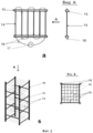
Для реализации заявляемого способа предложено устройство, схематически изображенное на Фиг.1 и 2.To implement the proposed method, a device is proposed, schematically depicted in figures 1 and 2.
На Фиг.1 с помощью фронтального (а) и горизонтального (б) разрезов показана схема предлагаемого устройства, в котором в качестве нагревательных элементов использованы нихромовые стержни. На Фиг.2 показаны схема съемной нагревательной кассеты (а), и с помощью изометрического вида и вида сверху (вид А) - схема блока нагревательных кассет (б).Figure 1 using the front (a) and horizontal (b) sections shows a diagram of the proposed device, in which nichrome rods are used as heating elements. Figure 2 shows a diagram of a removable heating cassette (a), and using an isometric view and a top view (view A) is a diagram of a block of heating cassettes (b).
Устройство содержит загрузочную мерную емкость 1, снабженную на входе и выходе заслонками 2. Для удобства заполнения пиролизной камеры 3 перерабатываемым сырьем 4 между загрузочной емкостью и пиролизной камерой может быть установлен конусный переходник 5, нижнее сечение которого соответствует горизонтальному сечению пиролизной камеры, которая, предпочтительно, имеет прямоугольную форму. Стенки пиролизной камеры 3, одна из которых может быть выполнена съемной, могут быть изготовлены из любого прочного термостойкого материала, например термостойкого пластика или дюраля. Стенки пиролизной камеры снабжены отверстиями 6 для выхода первичных парогазовых продуктов пиролиза. Диаметр и количество этих отверстий выбирают такими, чтобы при сохранении необходимых прочностных характеристик корпуса пиролизной камеры обеспечить максимальную проницаемость стенок для парогазовой смеси и при этом не допустить проникновение перерабатываемой смеси за пределы камеры.The device comprises a loading measuring tank 1, provided with inlet and outlet valves 2. For convenience, filling the pyrolysis chamber 3 with processed raw material 4, a conical adapter 5 can be installed between the loading tank and the pyrolysis chamber, the lower section of which corresponds to the horizontal section of the pyrolysis chamber, which, preferably has a rectangular shape. The walls of the pyrolysis chamber 3, one of which can be made removable, can be made of any durable heat-resistant material, such as heat-resistant plastic or duralumin. The walls of the pyrolysis chamber are provided with
Снаружи пиролизной камеры установлены любым конструкционным способом, например, на фланцах 7, конденсаторы 8, предназначенные для конденсации паровой фракции первичной парогазовой смеси, представляющие собой охлаждаемые поверхности, форма и расположение которых должны обеспечить эффективную конденсацию паровой фракции выходящих из пиролизной камеры парогазовых продуктов. Охлаждаемые поверхности могут иметь любую технически обоснованную форму, например, могут быть плоскими или изогнутыми, и при этом могут быть ориентированы параллельно оси пиролизной камеры или под углом к ней. Расстояние между наружными стенками пиролизной камеры и охлаждаемыми поверхностями должно быть минимально возможным с тем, чтобы обеспечить быстрое попадание продуктов пиролиза на поверхность конденсатора до возникновения в них вторичных реакций разложения. Это расстояние, в зависимости от состава парогазовой фракции, конструктивных особенностей устройства и его размеров, может составлять от 0,5 см до десятков сантиметров. Конденсаторы могут охлаждаться любым технически доступным способом, например, с помощью внутренних каналов, по которым пропускают хладагенты, обеспечивающие необходимую температуру конденсации. Температуру конденсаторов регулируют любым подходящим способом, например, с использованием термопары, связанной с блоком управления скоростью подачи хладагента (на схеме не показаны). Для сбора конденсата предназначены приемные емкости 9. В нижней части пиролизная камера соединена через заслонку 10 с приемной емкостью 11 для твердых продуктов пиролиза. Устройство заключено в герметичный прямоугольный корпус 12, смонтированный из любого прочного материала, например железобетонных плит, одна из стенок корпуса выполнена открываемой или отодвигаемой для выемки жидких и твердых продуктов и проведения монтажных и ремонтных работ. В верхней части пространства между пиролизной камерой и корпусом имеется патрубок 13 для выхода газовой смеси (биогаза) в приемник для ее очистки в целях возможного использования в качестве топлива в электрогенераторе (на схеме не показаны).Outside the pyrolysis chamber, in any constructional manner, for example, on flanges 7, condensers 8 are used for condensing the vapor fraction of the primary vapor-gas mixture, which are cooled surfaces, the shape and arrangement of which should ensure the effective condensation of the vapor fraction of the vapor-gas products leaving the pyrolysis chamber. The cooled surfaces can be of any technically feasible shape, for example, they can be flat or curved, and in this case they can be oriented parallel to the axis of the pyrolysis chamber or at an angle to it. The distance between the outer walls of the pyrolysis chamber and the cooled surfaces should be as small as possible in order to ensure that pyrolysis products quickly reach the condenser surface before secondary decomposition reactions occur in them. This distance, depending on the composition of the gas-vapor fraction, the design features of the device and its size, can be from 0.5 cm to tens of centimeters. Condensers can be cooled in any technically accessible way, for example, using internal channels through which refrigerants pass, providing the required condensation temperature. The temperature of the condensers is controlled by any suitable method, for example, using a thermocouple connected to the refrigerant feed rate control unit (not shown in the diagram). For collecting condensate, receiving tanks are designed 9. In the lower part, the pyrolysis chamber is connected through a shutter 10 to a receiving tank 11 for solid pyrolysis products. The device is enclosed in a sealed rectangular housing 12, mounted of any durable material, such as reinforced concrete slabs, one of the walls of the housing is made open or retractable for the removal of liquid and solid products and for installation and repair work. In the upper part of the space between the pyrolysis chamber and the housing there is a nozzle 13 for the exit of the gas mixture (biogas) into the receiver for its cleaning for possible use as fuel in an electric generator (not shown in the diagram).
Внутри пиролизной камеры по всему ее объему послойно размещены нагревательные элементы 14, выполненные из коррозионно- и термостойкого токопроводящего материала с высоким удельным электрическим сопротивлением, например, нихрома. Нагревательные элементы могут быть выполнены, преимущественно, в форме стержней, но возможна и любая другая форма с использованием проволоки (например, в форме спирали).Inside the pyrolysis chamber throughout its entire volume,
Нагревательные элементы размещены внутри пиролизной камеры таким образом, что ее объем разделен на локально нагреваемые ячейки, что обеспечивает быстрый нагрев перерабатываемой массы по всему объему пиролизной камеры и существенно облегчает ее масштабирование. Удобно использовать такое расположение нагревательных элементов, при котором в каждом слое они ориентированы взаимно параллельно, а нагревательные элементы, находящиеся в соседних слоях, ориентированы взаимно перпендикулярно, так что на схематическом виде сверху они образуют прямоугольные ячейки, как показано на Фиг.16 и на Фиг 26. Геометрические размеры нагревательных элементов и мощность подаваемых на них электроимпульсов выбирают исходя из габаритов устройства, вида перерабатываемой смеси и требуемых частотных параметров импульсов.The heating elements are placed inside the pyrolysis chamber in such a way that its volume is divided into locally heated cells, which ensures rapid heating of the processed mass throughout the entire volume of the pyrolysis chamber and substantially facilitates its scaling. It is convenient to use an arrangement of heating elements in which they are oriented mutually in parallel in each layer, and heating elements located in adjacent layers are oriented mutually perpendicularly, so that in a schematic plan view from above they form rectangular cells, as shown in FIG. 16 and FIG. 26. The geometric dimensions of the heating elements and the power of the electrical pulses supplied to them are selected based on the dimensions of the device, the type of mixture being processed and the required frequency parameters of the pulses .
Для электропитания нагревательных элементов используют источник постоянного или переменного тока, преимущественно электрогенератор, ток которого с помощью электронного переключателя, например семисторного переключателя, включающего в себя таймер или электронный блок управления по специальной программе, преобразуют в электроимпульсы заданной формы и частоты.For power supply of the heating elements, a direct or alternating current source is used, mainly an electric generator, the current of which is converted into electrical pulses of a given shape and frequency using an electronic switch, for example a seven-switch switch, which includes a timer or an electronic control unit according to a special program.
С целью облегчения эксплуатации устройства, замены нагревательных элементов, проведения ремонтных и профилактических работ нагревательные элементы с помощью крепежных реек 15 вместе с электропроводкой 16 от электронного блока переключателя 17 могут быть объединены в плоские съемные кассеты (см. Фиг.2а), сконструированные с возможностью варьирования расстояния между нагревательными элементами в зависимости от степени дисперсности перерабатываемого сырья и его свойств. Съемные нагревательные кассеты с помощью вертикальных крепежных стоек 18 могут быть закреплены в кассетном блоке (Фиг.2б). Крепежные стойки могут устанавливаться на электромагнитные вибробашмаки 19, передающие кассетному блоку колебательные импульсы, способствующие прохождению перерабатываемой смеси сквозь ячейки, образованные нагревательными элементами. Съемные нагревательные кассеты могут быть размещены в кассетном блоке таким образом, чтобы в соседних слоях нагревательные элементы были расположены перпендикулярно друг другу (Фиг.2б), что и позволяет разделить рабочую зону пиролизной камеры на локально нагреваемые объемные ячейки. Описанное устройство кассетного блока и съемных нагревательных кассет позволяет при необходимости варьировать размер локальных объемных ячеек по высоте и горизонтальному сечению пиролизной камеры в зависимости от степени дисперсности и свойств перерабатываемого сырья. Кассетный блок устанавливают в пиролизной камере таким образом, что опорные стойки располагаются в углах пиролизной камеры параллельно ее продольной оси.In order to facilitate the operation of the device, replace the heating elements, carry out repair and maintenance work, the heating elements using mounting
Внутри пиролизной камеры размещены датчики 20 для измерения значений величины проводимости по ее объему, соединенные с электронным переключателем, управляющим включением и отключением электропитания нагревательных элементов.Sensors 20 are placed inside the pyrolysis chamber for measuring the values of conductivity by its volume, connected to an electronic switch that controls the on and off power supply of the heating elements.
Для удобства эксплуатации и обслуживания пиролизная камера может быть установлена на роликовые салазки (не показаны), облегчающие ее перемещение.For ease of operation and maintenance, the pyrolysis chamber can be mounted on a roller slide (not shown) to facilitate its movement.
Устройство работает следующим образом.The device operates as follows.
Загрузочную мерную емкость 1, играющую одновременно роль дозатора, заполняют предназначенной для переработки смесью, закрывают верхнюю заслонку 2 в целях недопущения выхода продуктов пиролиза в атмосферу, открывают нижнюю заслонку 2, и смесь через конусный переходник 5 поступает в пиролизную камеру 3 до ее полного заполнения, после чего нижнюю заслонку также закрывают в целях недопущения образования застойных зон, заполненных горючими газами. Выходное сечение переходной емкости соответствует поперечному сечению пиролизной камеры, что позволяет загружать сырье, содержащее фрагменты, размер которых может превосходить расстояние между нагревательными элементами. Основная часть сырья попадает в пространство между нагревательными элементами, заполняя объем пиролизной камеры, а крупные фрагменты задерживаются на верхнем слое нагревательных элементов. Включают источник электропитания, в частности электрогенератор, и с помощью электронного переключателя подают импульсы тока на нагревательные элементы, которые, в соответствии с заявляемым способом, осуществляют импульсный нагрев смеси. Температуру нагревательных элементов контролируют с помощью термопары (не показана). Под действием тепловых импульсов крупные фрагменты перерабатываются и опускаются внутрь камеры в пространство между нагревательными элементами, где они подвергаются полному пиролизу. В случае, если крупные фрагменты сырья не удается переработать полностью, они удаляются в ходе выемки продуктов.The loading measuring tank 1, which simultaneously plays the role of a dispenser, is filled with the mixture intended for processing, the upper valve 2 is closed in order to prevent the release of pyrolysis products into the atmosphere, the lower valve 2 is opened, and the mixture through the conical adapter 5 enters the pyrolysis chamber 3 until it is completely filled, then the lower shutter is also closed to prevent the formation of stagnant zones filled with combustible gases. The output section of the transition tank corresponds to the cross section of the pyrolysis chamber, which allows you to load raw materials containing fragments, the size of which may exceed the distance between the heating elements. The bulk of the raw material enters the space between the heating elements, filling the volume of the pyrolysis chamber, and large fragments are retained on the upper layer of the heating elements. The power supply is turned on, in particular the electric generator, and using an electronic switch, current pulses are supplied to the heating elements, which, in accordance with the inventive method, carry out pulse heating of the mixture. The temperature of the heating elements is controlled using a thermocouple (not shown). Under the influence of thermal pulses, large fragments are processed and lowered into the chamber into the space between the heating elements, where they undergo complete pyrolysis. In case large fragments of raw materials cannot be completely processed, they are removed during the extraction of products.
Конструкция устройства позволяет варьировать расстояния между нагревательными элементами в нагревательной кассете и расстояния между кассетами в кассетном блоке, что позволяет заранее устанавливать геометрические размеры объемных ячеек в соответствии со степенью дисперсности смеси так, чтобы верхние ячейки соответствовали максимальным размерам фрагментов смеси, а нижние - минимальным.The design of the device allows you to vary the distance between the heating elements in the heating cassette and the distance between the cassettes in the cassette unit, which allows you to pre-set the geometric dimensions of the volume cells in accordance with the degree of dispersion of the mixture so that the upper cells correspond to the maximum sizes of the fragments of the mixture, and the lower ones to the minimum.
Импульсное электропитание нагревательных элементов осуществляют, преимущественно, от электрогенератора. При этом электроимпульсы формируются с использованием электронного переключателя, например семисторного, управляемого с помощью таймера переключателя или электронного блока, управляемого специальной программой. Используют, преимущественно, газовые электрогенераторы, работающие, преимущественно, на «биогазе», получаемом в процессе пиролиза смеси описанным выше способом.The pulse power supply of the heating elements is carried out mainly from an electric generator. In this case, electrical pulses are generated using an electronic switch, for example a seven-phase, controlled by a switch timer or an electronic unit controlled by a special program. Mostly gas generators are used, operating mainly on “biogas” obtained in the process of pyrolysis of the mixture as described above.
На этапе загрузки и на этапе переработки сырья в целях облегчения его загрузки, перемещения и выгрузки продуктов перерабатываемая смесь может подвергаться вибровоздействию со стороны кассетного блока, получающего импульсы от электромагнитных вибробашмаков 19, на которых установлены крепежные стойки кассетного блока.At the loading stage and at the processing stage of raw materials in order to facilitate its loading, moving and unloading products, the processed mixture may be subjected to vibration from the side of the cassette unit, receiving pulses from electromagnetic vibratory shoes 19, on which the mounting racks of the cassette unit are installed.
Образующиеся первичные парогазовые продукты пиролиза выходят через отверстия в стенках пиролизной камеры и направляются на охлаждаемые поверхности (конденсаторы), расположенные так, чтобы обеспечить максимально быстрое попадание на них компонентов парогазовой смеси, и, тем самым, минимизировать протекание вторичных реакций разложения, снижающих выход жидкой фракции. Охлаждаемые поверхности могут быть плоскими или изогнутыми, т.е. иметь любую форму, обеспечивающую максимальную эффективность конденсации. В зависимости от специфики перерабатываемого сырья и конструктивных особенностей устройства, расстояние от наружных стенок пиролизной камеры до конденсаторов может составлять от 0,5 см до десятков сантиметров. При более близком расположении возрастает сопротивление потоку и снижается его скорость, что увеличивает время пребывания парогазовых продуктов в горячей зоне. К аналогичным последствиям приводит и излишняя удаленность конденсаторов от стенок пиролизной камеры. Площадь конденсирующих поверхностей выбирают исходя из условия максимальной эффективности конденсации паров. Образовавшийся конденсат стекает вдоль стенок конденсирующих поверхностей в приемные емкости 9.The resulting primary gas-vapor pyrolysis products exit through openings in the walls of the pyrolysis chamber and are directed to cooled surfaces (condensers) located so as to ensure that the components of the gas-vapor mixture reach them as quickly as possible, and thereby minimize the occurrence of secondary decomposition reactions that reduce the yield of the liquid fraction . The cooled surfaces may be flat or curved, i.e. have any shape that provides maximum condensation efficiency. Depending on the specifics of the processed raw materials and the design features of the device, the distance from the outer walls of the pyrolysis chamber to the capacitors can be from 0.5 cm to tens of centimeters. At a closer location, resistance to flow increases and its speed decreases, which increases the residence time of gas-vapor products in the hot zone. Excessive remoteness of capacitors from the walls of the pyrolysis chamber leads to similar consequences. The area of the condensing surfaces is selected based on the conditions of maximum vapor condensation efficiency. The resulting condensate flows along the walls of the condensing surfaces in the receiving tank 9.
После завершения пиролиза загруженного в камеру сырья, о чем судят по показаниям датчиков 20, открывают заслонку 10 и твердые продукты собирают в приемнике 11. Выемку приемников с продуктами осуществляют путем отодвигания (открытия) подвижной стенки корпуса устройства.After completion of the pyrolysis of the raw materials loaded into the chamber, as judged by the readings of the sensors 20, the shutter 10 is opened and solid products are collected in the receiver 11. The receivers with the products are removed by moving (opening) the movable wall of the device body.
Оставшаяся газовая смесь попадает через канал 13 в разделительную камеру (на схеме не показана), в которой происходит очистка горючих газов, которые могут использоваться в качестве топлива в электрогенераторе.The remaining gas mixture enters through the channel 13 into the separation chamber (not shown in the diagram), in which the cleaning of combustible gases, which can be used as fuel in the generator.
Процесс пиролиза контролируют по показаниям датчиков 20 проводимости продуктов переработки смеси в нижней части пиролизной камеры. Достижение уровня сигнала, соответствующего величине, установленной предварительно в тестовых испытаниях, приводит к автоматическому отключению электропитания нагревательных элементов. После окончания пиролиза и выгрузки из пиролизной камеры твердых продуктов процесс может быть повторен в отношении новой порции смеси.The pyrolysis process is controlled by the readings of the sensors 20 conductivity of the products of the processing of the mixture in the lower part of the pyrolysis chamber. Achieving a signal level corresponding to the value set previously in the test tests leads to an automatic shutdown of the power supply of the heating elements. After pyrolysis is complete and solid products are unloaded from the pyrolysis chamber, the process can be repeated with respect to a new portion of the mixture.
Предлагаемые способ и устройство могут быть использованы для проведения в промышленных масштабах быстрого пиролиза биомасс и углеводородсодержащих неизмельченных смесей различного происхождения, включающих, в том числе, и крупные фрагменты, и позволяет с максимальным выходом получать жидкую фракцию, которая может быть использована в качестве альтернативного топлива, а также для получения химических продуктов. При этом исключается попадание вредных продуктов в окружающую среду. Предлагаемое устройство может быть масштабировано в широких пределах и использовано в мобильном варианте непосредственно на месте нахождения подлежащих переработке биомасс или углеводородсодержащих смесей, что обеспечивает экономию на транспортировочных расходах.The proposed method and device can be used for industrial-scale rapid pyrolysis of biomass and hydrocarbon-containing unmilled mixtures of various origins, including, including large fragments, and allows you to obtain a liquid fraction with maximum yield, which can be used as an alternative fuel, as well as for chemical products. This eliminates the ingress of harmful products into the environment. The proposed device can be scaled over a wide range and used in the mobile version directly at the location of the biomass or hydrocarbon-containing mixtures to be processed, which ensures savings in transportation costs.
Claims (22)
Priority Applications (1)
| Application Number | Priority Date | Filing Date | Title |
|---|---|---|---|
| RU2012147357/05A RU2524110C2 (en) | 2012-11-08 | 2012-11-08 | Fast pyrolysis of biomass and hydrocarbon-bearing products and device to this end |
Applications Claiming Priority (1)
| Application Number | Priority Date | Filing Date | Title |
|---|---|---|---|
| RU2012147357/05A RU2524110C2 (en) | 2012-11-08 | 2012-11-08 | Fast pyrolysis of biomass and hydrocarbon-bearing products and device to this end |
Publications (2)
| Publication Number | Publication Date |
|---|---|
| RU2012147357A RU2012147357A (en) | 2014-05-20 |
| RU2524110C2 true RU2524110C2 (en) | 2014-07-27 |
Family
ID=50695385
Family Applications (1)
| Application Number | Title | Priority Date | Filing Date |
|---|---|---|---|
| RU2012147357/05A RU2524110C2 (en) | 2012-11-08 | 2012-11-08 | Fast pyrolysis of biomass and hydrocarbon-bearing products and device to this end |
Country Status (1)
| Country | Link |
|---|---|
| RU (1) | RU2524110C2 (en) |
Cited By (8)
| Publication number | Priority date | Publication date | Assignee | Title |
|---|---|---|---|---|
| RU2596169C1 (en) * | 2015-08-26 | 2016-08-27 | Трусов Федор Николаевич | Fast pyrolysis reactor |
| RU2630687C1 (en) * | 2017-01-16 | 2017-09-12 | Спивак Алина Владимировна | Method of recycling of solid and liquid hydrocarbon-bearing wastes and obtaining synthetic liquid fuels from it |
| RU2644895C2 (en) * | 2016-07-27 | 2018-02-14 | Федеральное государственное бюджетное образовательное учреждение высшего образования "Тверской государственный университет" (ТвГУ) | Method of processing carbon-containing waste of vegetable origin |
| RU2684878C1 (en) * | 2018-04-28 | 2019-04-15 | Федеральное государственное бюджетное учреждение науки Удмуртский федеральный исследовательский центр Уральского отделения Российской академии наук | Device for disposal of municipal solid waste |
| RU2696231C1 (en) * | 2018-10-26 | 2019-07-31 | Общество С Ограниченной Ответственностью "Нпк "Энергоэффективные Технологии" | Method of recycling carbon-containing materials |
| RU2717778C1 (en) * | 2019-08-27 | 2020-03-25 | Павел Феликсович Джулай | Reactor for pyrolysis of raw material containing organic compounds |
| US11753591B2 (en) | 2021-03-08 | 2023-09-12 | Extiel AP, LLC | Device for pyrolysis of carbonaceous materials and method |
| RU2808265C1 (en) * | 2022-12-28 | 2023-11-28 | Сергей Вильевич Магазов | Waste disposal method |
Citations (4)
| Publication number | Priority date | Publication date | Assignee | Title |
|---|---|---|---|---|
| RU2039078C1 (en) * | 1992-07-17 | 1995-07-09 | Валентин Сергеевич Петров | Method of plant origin materials thermic treatment and device for its realization |
| RU2201951C1 (en) * | 2002-01-16 | 2003-04-10 | Вайнштейн Эдуард Фридрихович | Method of processing organic substances |
| RU2225573C1 (en) * | 2002-07-29 | 2004-03-10 | Глушков Владимир Александрович | Installation for pyrolysis of hydrocarbon waste products |
| RU2451880C2 (en) * | 2009-09-18 | 2012-05-27 | Владимир Александрович Котельников | Method to process carbon-containing solid substances by method of quick pyrolysis (versions) |
-
2012
- 2012-11-08 RU RU2012147357/05A patent/RU2524110C2/en active
Patent Citations (4)
| Publication number | Priority date | Publication date | Assignee | Title |
|---|---|---|---|---|
| RU2039078C1 (en) * | 1992-07-17 | 1995-07-09 | Валентин Сергеевич Петров | Method of plant origin materials thermic treatment and device for its realization |
| RU2201951C1 (en) * | 2002-01-16 | 2003-04-10 | Вайнштейн Эдуард Фридрихович | Method of processing organic substances |
| RU2225573C1 (en) * | 2002-07-29 | 2004-03-10 | Глушков Владимир Александрович | Installation for pyrolysis of hydrocarbon waste products |
| RU2451880C2 (en) * | 2009-09-18 | 2012-05-27 | Владимир Александрович Котельников | Method to process carbon-containing solid substances by method of quick pyrolysis (versions) |
Cited By (10)
| Publication number | Priority date | Publication date | Assignee | Title |
|---|---|---|---|---|
| RU2596169C1 (en) * | 2015-08-26 | 2016-08-27 | Трусов Федор Николаевич | Fast pyrolysis reactor |
| WO2017034437A3 (en) * | 2015-08-26 | 2017-04-20 | ТРУСОВ, Федор Николаевич | Fast pyrolysis reactor |
| EA033034B1 (en) * | 2015-08-26 | 2019-08-30 | ТРУСОВ, Федор Николаевич | Fast pyrolysis reactor |
| RU2644895C2 (en) * | 2016-07-27 | 2018-02-14 | Федеральное государственное бюджетное образовательное учреждение высшего образования "Тверской государственный университет" (ТвГУ) | Method of processing carbon-containing waste of vegetable origin |
| RU2630687C1 (en) * | 2017-01-16 | 2017-09-12 | Спивак Алина Владимировна | Method of recycling of solid and liquid hydrocarbon-bearing wastes and obtaining synthetic liquid fuels from it |
| RU2684878C1 (en) * | 2018-04-28 | 2019-04-15 | Федеральное государственное бюджетное учреждение науки Удмуртский федеральный исследовательский центр Уральского отделения Российской академии наук | Device for disposal of municipal solid waste |
| RU2696231C1 (en) * | 2018-10-26 | 2019-07-31 | Общество С Ограниченной Ответственностью "Нпк "Энергоэффективные Технологии" | Method of recycling carbon-containing materials |
| RU2717778C1 (en) * | 2019-08-27 | 2020-03-25 | Павел Феликсович Джулай | Reactor for pyrolysis of raw material containing organic compounds |
| US11753591B2 (en) | 2021-03-08 | 2023-09-12 | Extiel AP, LLC | Device for pyrolysis of carbonaceous materials and method |
| RU2808265C1 (en) * | 2022-12-28 | 2023-11-28 | Сергей Вильевич Магазов | Waste disposal method |
Also Published As
| Publication number | Publication date |
|---|---|
| RU2012147357A (en) | 2014-05-20 |
Similar Documents
| Publication | Publication Date | Title |
|---|---|---|
| RU2524110C2 (en) | Fast pyrolysis of biomass and hydrocarbon-bearing products and device to this end | |
| US9545609B2 (en) | Pyrolysis oil made with a microwave-transparent reaction chamber for production of fuel from an organic-carbon-containing feedstock | |
| US8361282B2 (en) | System and method using a microwave-transparent reaction chamber for production of fuel from a carbon-containing feedstock | |
| US9873841B2 (en) | Entrained-flow gasifier and gasification method using the same for synthesizing syngas from biomass fuel | |
| RU2392543C2 (en) | Method and device for processing of domestic and industrial organic wastes | |
| MX2011004135A (en) | Apparatus and process for thermal decomposition of any kind of organic material. | |
| JP2012515807A (en) | System and method for fractionating components of biomass | |
| KR20160085743A (en) | Char made with a microwave system | |
| JP2024514408A (en) | Device and method for pyrolyzing carbon materials | |
| RU2688568C1 (en) | Method of processing organic material to produce synthetic high-calorie gas in high-temperature ablation pyrolysis unit | |
| EP2564667A1 (en) | Microwave and radio frequency material processing | |
| CN110546240A (en) | device for treating coal and domestic garbage | |
| RU2544635C1 (en) | Method and device for flash-pyrolysis of hydrocarbon materials using induction heating | |
| RU2644895C2 (en) | Method of processing carbon-containing waste of vegetable origin | |
| RU2613063C2 (en) | Zolotarev pyrolysis reactor | |
| CN205501194U (en) | Combination unit of low order coal catalytic degradation | |
| RU127879U1 (en) | DEVICE FOR RESEARCH OF THE PROCESS OF THERMAL DECOMPOSITION OF SOLID FUELS | |
| RU2816423C1 (en) | Installation for processing solid organic waste | |
| RU149820U1 (en) | GAS GENERATOR PLANT FOR THE PROCESSING OF CONDENSED ORGANIC FUEL | |
| RU61844U1 (en) | COMPLEX FOR THE PROCESSING OF SOLID DOMESTIC WASTE | |
| RU2554953C1 (en) | Method of processing of condensed organic fuel, and gas-generating unit | |
| RU2760246C1 (en) | Waste disposal device | |
| WO2019074468A1 (en) | Rapid pyrolysis method and installation for the implementation thereof | |
| RU2848523C1 (en) | Method for low-temperature microwave pyrolysis of carbon-containing materials and apparatus for implementing method | |
| RU2596169C1 (en) | Fast pyrolysis reactor |
Legal Events
| Date | Code | Title | Description |
|---|---|---|---|
| QB4A | Licence on use of patent |
Free format text: LICENCE Effective date: 20150528 |
|
| QB4A | Licence on use of patent |
Free format text: LICENCE Effective date: 20150925 |