RU2575889C2 - Method and device for can body forming - Google Patents
Method and device for can body forming Download PDFInfo
- Publication number
- RU2575889C2 RU2575889C2 RU2013111458/02A RU2013111458A RU2575889C2 RU 2575889 C2 RU2575889 C2 RU 2575889C2 RU 2013111458/02 A RU2013111458/02 A RU 2013111458/02A RU 2013111458 A RU2013111458 A RU 2013111458A RU 2575889 C2 RU2575889 C2 RU 2575889C2
- Authority
- RU
- Russia
- Prior art keywords
- stamp
- annular
- punch
- specified
- central
- Prior art date
Links
- 238000000034 method Methods 0.000 title claims description 11
- 229910052751 metal Inorganic materials 0.000 claims abstract description 12
- 239000002184 metal Substances 0.000 claims abstract description 12
- 230000002093 peripheral effect Effects 0.000 claims abstract description 7
- 230000015572 biosynthetic process Effects 0.000 claims description 5
- 230000013011 mating Effects 0.000 claims description 3
- 238000003780 insertion Methods 0.000 claims description 2
- 230000037431 insertion Effects 0.000 claims description 2
- 238000006073 displacement reaction Methods 0.000 claims 2
- ATJFFYVFTNAWJD-UHFFFAOYSA-N Tin Chemical compound [Sn] ATJFFYVFTNAWJD-UHFFFAOYSA-N 0.000 claims 1
- 230000000977 initiatory effect Effects 0.000 claims 1
- 230000003993 interaction Effects 0.000 claims 1
- 238000013016 damping Methods 0.000 abstract 1
- 230000000694 effects Effects 0.000 abstract 1
- 238000010327 methods by industry Methods 0.000 abstract 1
- 239000000126 substance Substances 0.000 abstract 1
- 238000004519 manufacturing process Methods 0.000 description 8
- 229910052782 aluminium Inorganic materials 0.000 description 3
- XAGFODPZIPBFFR-UHFFFAOYSA-N aluminium Chemical compound [Al] XAGFODPZIPBFFR-UHFFFAOYSA-N 0.000 description 3
- 239000006096 absorbing agent Substances 0.000 description 2
- 230000006835 compression Effects 0.000 description 2
- 238000007906 compression Methods 0.000 description 2
- 238000013461 design Methods 0.000 description 2
- 239000000463 material Substances 0.000 description 2
- 230000035939 shock Effects 0.000 description 2
- 241000283216 Phocidae Species 0.000 description 1
- 241001671983 Pusa Species 0.000 description 1
- 229910000831 Steel Inorganic materials 0.000 description 1
- 125000001246 bromo group Chemical group Br* 0.000 description 1
- 238000010276 construction Methods 0.000 description 1
- 238000001816 cooling Methods 0.000 description 1
- 238000000605 extraction Methods 0.000 description 1
- 239000012634 fragment Substances 0.000 description 1
- 238000010438 heat treatment Methods 0.000 description 1
- 238000012423 maintenance Methods 0.000 description 1
- 238000012986 modification Methods 0.000 description 1
- 230000004048 modification Effects 0.000 description 1
- 239000011148 porous material Substances 0.000 description 1
- 230000001105 regulatory effect Effects 0.000 description 1
- 238000007789 sealing Methods 0.000 description 1
- 239000010959 steel Substances 0.000 description 1
- 230000001502 supplementing effect Effects 0.000 description 1
- XLYOFNOQVPJJNP-UHFFFAOYSA-N water Substances O XLYOFNOQVPJJNP-UHFFFAOYSA-N 0.000 description 1
Images
Abstract
Description
Настоящее изобретение относится к способу и устройству для формирования корпуса банки из листовой стали или листового алюминия, например, такому, как способы и устройства или инструментальная оснастка, раскрытые в патентах США 4713958, 4716755, 4808052, 4955223, 6658911 и 7302822. Раскрытия этих патентов включено здесь в качестве ссылки, дополняющей подробное описание настоящего изобретения.The present invention relates to a method and apparatus for forming a can body of sheet steel or sheet aluminum, for example, such as the methods and devices or tooling disclosed in US Pat. Nos. 4,713,958, 4,716,755, 4,880,552, 4,955,223, 6,658,911 and 7,302,822. Disclosures of these patents are included here by reference, supplementing the detailed description of the present invention.
В такой инструментальной оснастке или устройстве желательно, чтобы устройство конструировалось для использования в механическом прессе одинарного действия (как раскрыто в вышеупомянутых патентах 4955223 и 7302822), а также для использования в механическом прессе двойного действия (как раскрыто в вышеупомянутых патентах 4716755 и 6658911). Конструкция высокопроизводительного пресса одинарного действия более проста и более экономична в работе и обслуживании и может эффективно эксплуатироваться, например, с ходом 1,75 дюйма и со скоростью 650 ходов в минуту. В данной области техники используется намного больше высокопроизводительных прессов одинарного действия, чем прессов двойного действия.In such a tooling or device, it is desirable that the device is designed for use in a single-action mechanical press (as disclosed in the aforementioned patents 4955223 and 7302822), as well as for use in a double-action mechanical press (as disclosed in the aforementioned patents 4716755 and 6658911). The design of a high-performance single-action press is simpler and more economical in operation and maintenance and can be effectively operated, for example, with a stroke of 1.75 inches and at a speed of 650 strokes per minute. Many more single-acting high-performance presses are used in the art than double-acting presses.
Также желательно, чтобы устройство или инструментальная оснастка включала в себя внутреннюю нажимную втулку и внешнюю нажимную втулку, а также желательно эксплуатировать обе втулки с избыточным давлением воздуха, но при этом надо избегать использования внутренней нажимной втулки, имеющей расположенные по периферии и растягивающиеся по оси пружины (например, раскрытые в патенте 7302822), или избегать применения расположенных по окружности и растягивающихся по оси пальцев (например, раскрытых в патенте 4716755). Быстрое осевое возвратно-поступательное движение пальцев и одного поршня, который приводит в действие пальцы, дополнительно вырабатывает нежелательное тепло, а также препятствует созданию настраиваемого и точно регулируемого осевого усилия на внутреннюю нажимную втулку при использовании пружин сжатия.It is also desirable that the device or tooling include an internal pressure sleeve and an external pressure sleeve, and it is also desirable to operate both bushings with excess air pressure, but the use of an internal pressure sleeve having peripherally located and stretching axially springs ( for example, disclosed in patent 7302822), or to avoid the use of circumferentially extending and extending along the axis of the fingers (for example, disclosed in patent 4716755). The fast axial reciprocating movement of the fingers and one piston that drives the fingers additionally generates unwanted heat, and also prevents the creation of a customizable and precisely adjustable axial force on the internal pressure sleeve when using compression springs.
Помимо этого, во время работы пресса с высокой скоростью желательно также иметь точно регулируемое постоянное усилие, оказываемое на листовой материал внешней нажимной втулкой, чтобы избежать утонения материала между внешней нажимной втулкой и кольцевым сердечником штампа. Точно регулируемое давление воздуха на внутреннюю нажимную втулку желательно также для удержания внутреннего свода и наклонной стенки корпуса банки при формировании фаски, панельной стенки и центральной панели корпуса банки без утонения листового металла. Кроме того, желательно свести к минимуму вертикальную высоту инструментальной оснастки, используемой для изготовления корпусов банок, чтобы использовать большее количество известных высокопроизводительных прессов одинарного действия и работать с более высокими скоростями с меньшим выделением тепла, с тем, чтобы избежать использования водяной системы охлаждения. После обзора упомянутых выше патентов, специалистам очевидно, что ни один из этих патентов не обеспечивает все упомянутые выше желательные признаки.In addition, while the press is operating at high speed, it is also desirable to have a precisely controlled constant force exerted on the sheet material by the external pressure sleeve in order to avoid thinning of the material between the external pressure sleeve and the die ring core. A precisely controlled air pressure on the inner pressure sleeve is also desirable for holding the inner arch and the inclined wall of the can body while forming a chamfer, panel wall and the central panel of the can body without thinning the sheet metal. In addition, it is desirable to minimize the vertical height of the tooling used to make can bodies to use more known single-acting high-performance presses and operate at higher speeds with less heat to avoid the use of a water cooling system. After reviewing the above patents, it will be apparent to those skilled in the art that none of these patents provides all of the desirable features mentioned above.
Краткое описание изобретенияSUMMARY OF THE INVENTION
Настоящее изобретение имеет целью улучшить способ и устройство или оснастку для высокопроизводительного производства корпусов банок, а также обеспечить все упомянутые выше желательные признаки. Инструментальная оснастка по настоящему изобретению также идеально подходит для изготовления корпуса банки (типа банки, раскрытой в патенте 7341163 заявителя и в опубликованной патентной заявке US-2005-0029269 заявителя, раскрытие которой также включено здесь в качестве ссылки). Способ и устройство или инструментальная оснастка по настоящему изобретению, в частности, особенно подходят для использования на прессе одинарного и двойного действия и для изготовления однородных и точных по размеру корпусов банок на высокопроизводительном прессе с минимальным выделением тепла, чтобы во время работы избежать тепловой деформации инструментальной оснастки.The present invention aims to improve the method and apparatus or equipment for high-performance production of can cases, as well as to provide all of the above desirable features. The tooling of the present invention is also ideally suited for the manufacture of a can body (such as a can disclosed in Applicant Patent 7341163 and in Applicant Published Patent Application US-2005-0029269, the disclosure of which is also incorporated herein by reference). The method and apparatus or tooling of the present invention, in particular, is particularly suitable for use on a single and double acting press and for the manufacture of uniform and size-accurate can bodies on a high-performance press with minimal heat, so as to avoid thermal deformation of the tooling during operation .
В соответствии с одним проиллюстрированным вариантом настоящего изобретения, корпус банки формируется инструментальной оснасткой, включающей внутреннюю кольцевую нажимную втулку, которая расположена во внешней кольцевой нажимной втулке, и обе втулки имеют неразъемные поршни в соответствующих кольцевых воздушных поршневых камерах. Внешняя нажимная втулка находится в кольцевом вырубном и вытяжном штампе, прикрепленном к верхнему фиксатору, установленному на верхней плите штампа одинарного или двойного действия. Фиксатор также поддерживает центральный поршень штампа, который может служить опорой относительного осевого движения, а центральный поршень штампа поддерживает центральный пробойник штампа во внутренней нажимной втулке. Центральный поршень штампа определяет границы воздушной камеры, снабжаемой воздухом через впускное отверстие с регулируемым высоким давлением. Воздушная камера соединена с воздушной поршневой камерой внутренней нажимной втулки посредством большого количества разнесенных по периферии удлиненных воздушных амортизационных каналов. Воздушная поршневая камера внешней нажимной втулки снабжается воздухом, в основном с низким контролируемым давлением, через отдельное отверстие в верхнем фиксаторе.According to one illustrated embodiment of the present invention, the can body is formed by tooling including an internal annular pressure sleeve, which is located in the external annular pressure sleeve, and both bushings have integral pistons in the respective annular air piston chambers. The external pressure sleeve is located in an annular die-cut and exhaust stamp attached to the upper retainer mounted on the upper plate of a single or double-acting stamp. The latch also supports the central piston of the punch, which can support relative axial movement, and the central piston of the punch supports the central punch of the punch in the inner pressure sleeve. The central piston of the stamp defines the boundaries of the air chamber supplied with air through an inlet with a controlled high pressure. The air chamber is connected to the air piston chamber of the inner pressure sleeve by a large number of elongated air cushioning channels spaced around the periphery. The air piston chamber of the external pressure sleeve is supplied with air, mainly with a low controlled pressure, through a separate hole in the upper retainer.
Центральный пробойник штампа несет регулируемый вставной резец,- который инициирует вытяжку цилиндра из диска листового металла в штампе, зажатого между внешней нажимной втулкой и противоположным неподвижным кольцевым сердечником штампа, поддерживаемым нижним фиксатором, установленным на неподвижном нижней плите штампа. Указанная внутренняя нажимная втулка и кольцевой сердечник штампа имеют сопряженные фасонные поверхности, формирующие кольцевой внутренний свод и верхний участок наклонной стенки банки. Кольцевая юбка центрального пробойника штампа располагается вокруг вставного резца и имеет фасонную поверхность, которая сопрягается с фасонной поверхностью кольцевого сердечника штампа с целью формирования нижнего участка наклонной стенки, пока вставной резец заканчивает вытяжку цилиндра. Противоположный панельный пробойник имеет периферическую фасонную поверхность, которая образует центральную панель корпуса, а также кольцевую наклонную стенку панели и кольцевую фаску, как только центральный пробойник штампа возвращается в исходное положение. В другом варианте осуществления изобретения кольцевая воздушная поршневая камера для внешней нажимной втулки соединена с воздушными амортизационными каналами с помощью воздуховодов, причем кольцевая воздушная поршневая камера для внутренней нажимной втулки и кольцевая воздушная поршневая камера для внешней нажимной втулки получают одинаковое регулируемое давление подачи воздуха, что исключает необходимость различной подачи воздуха с различным давлением при эксплуатации инструментальной оснастки на подвижной нижней плите штампа.The central die punch carries an adjustable insert cutter, which initiates the extraction of the cylinder from the sheet metal disk in the die, sandwiched between the external pressure sleeve and the opposite stationary ring die core supported by a lower latch mounted on the stationary lower die plate. The specified inner pressure sleeve and the annular core of the stamp have mating shaped surfaces forming an annular inner arch and the upper portion of the inclined wall of the can. The annular skirt of the central punch of the stamp is located around the insert cutter and has a contoured surface that mates with the contoured surface of the annular core of the stamp in order to form the lower portion of the inclined wall until the insert cutter finishes drawing the cylinder. The opposite panel punch has a peripheral shaped surface that forms the center panel of the housing, as well as an annular inclined panel wall and an annular chamfer, as soon as the center punch of the stamp returns to its original position. In another embodiment of the invention, the annular air piston chamber for the external pressure sleeve is connected to the air cushioning channels via ducts, wherein the annular air piston chamber for the internal pressure sleeve and the annular air piston chamber for the external pressure sleeve receive the same adjustable air supply pressure, which eliminates the need different air supply with different pressure during the operation of tooling on the movable bottom plate of the stamp .
Другие признаки и преимущества настоящего изобретения станут ясными из приведенного далее описания, сопроводительных фигур и формулы изобретения.Other features and advantages of the present invention will become apparent from the following description, accompanying figures, and claims.
Краткое описание фигурBrief Description of the Figures
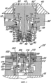
Фигура 1 представляет собой осевое сечение инструментальной оснастки, сконструированной и эксплуатируемой в соответствии с настоящим изобретением.Figure 1 is an axial section of a tooling designed and operated in accordance with the present invention.
Фигура 2 представляет собой осевое сечение инструментальной оснастки, показанной на Фигуре 1 и сконструированной и эксплуатируемой в соответствии с модификацией или другим вариантом настоящего изобретения.Figure 2 is an axial section of the tooling shown in Figure 1 and designed and operated in accordance with a modification or other embodiment of the present invention.
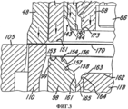
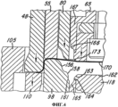
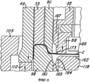
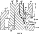
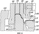
Фигуры 3-11 являются увеличенными сечениями фрагментов инструментальной оснастки, показанной на Фигурах 1 и 2; на них проиллюстрированы последовательные этапы изготовления корпуса банки на механическом прессе одинарного или двойного действия в соответствии с настоящим изобретением.Figures 3-11 are enlarged sections of fragments of the tooling shown in Figures 1 and 2; they illustrate the sequential steps of manufacturing a can body on a single or double acting mechanical press in accordance with the present invention.
Описание предпочтительных вариантов осуществления настоящего изобретенияDescription of preferred embodiments of the present invention
Обратимся к Фигуре 11, на которой изображен значительно увеличенный корпус 15, изготовленный из листового металла или алюминия, толщина которого составляет приблизительно 0,0082 дюйма. Корпус 15 включает плоскую круговую центральную панель 16, которая посредством участка панельной стенки 17, имеющего форму усеченного конуса или клиновидную конусообразную форму, а также в существенной степени цилиндрического участка панельной стенки 18 соединяется с кольцевой фаской 19, имеющей внутренний участок стенки 21, который наклонен или имеет форму усеченного конуса, а поперечное сечение которой в целом имеет U-образную конфигурацию. Указанная фаска 19 имеет слегка наклонный кольцевой участок внешней стенки 22, соединенный с кольцевым нижним участком наклонной стенки 23, который соединяется с загнутым вверх верхним участком наклонной стенки 24 посредством небольшого углового изгиба 25. Загнутый вверх участок 24 наклонной стенки соединяется с наклонным или имеющим форму усеченного конуса участком внутренней стенки 26 свода 28, имеющего направленный вниз участок внешнего периферического фланца 29. Конфигурация поперечного сечения или профиль корпуса 15 более конкретно раскрыт в упомянутой выше опубликованной патентной заявке US-2005-0029269 заявителя. Однако способ и устройство согласно этому изобретению также могут быть приспособлены для изготовления корпусов, имеющих различные профили в осевом поперечном сечении.Referring to Figure 11, which shows a significantly enlarged
Обратимся к Фигуре 1. Инструментальная оснастка 35 включает в себя кольцевой верхний фиксатор 38, установленный на верхней плите штампа 40 механического пресса одинарного или двойного действия. Указанный фиксатор 38 имеет цилиндрический участок 41, который выступает вверх внутрь стыкуемой полости 42 внутри верхней части штампа 40 и устанавливает границы камеры 44 сжатого воздуха. Кольцевой вырубной и вытяжной штамп 48 имеет выступающий наружу верхний фланцевый участок 49, который прикреплен к фиксатору 38 с помощью ряда периферийно расположенных винтов 51. Плоская заземляющая кольцевая прокладка 52 прикреплена к указанному верхнему фланцевому участку вытяжного и вырубного штампа 48, она обеспечивает точное осевое расположение штампа 48 относительно верхнего фиксатора 38.Turning to Figure 1.
Кольцевая внешняя нажимная втулка 55 служит опорой для осевого перемещения внутри вытяжного и вырубного штампа 48, и она имеет сформованный как единое целое поршень 56 с радиальными пластиковыми изнашивающими пальцами 57. Центральный поршень штампа 60 может служить опорой для осевого перемещения внутри верхнего фиксатора 38, он имеет нижний участок 62, который поддерживает центральный пробойник штампа 65, подвижно прикрепленный к указанному центральному поршню 60 центральным шурупом 66. Плоская заземляющая кольцевая прокладка 67 расположена между центральным пробойником штампа 65 и плечом на нижнем участке 62 центрального поршня штампа 60, что сделано для того, чтобы обеспечить точный выбор осевого размещения указанного центрального пробойника штампа на центральном поршне штампа 60. Кольцевой вставной резец 68 образует конец центрального пробойника штампа 65 и крепится с помощью ряда периферийно расположенных шурупов 69. Внутри центрального участка центрального поршня штампа 60 образована цилиндрическая камера-резервуар сжатого воздуха 70, закрываемая сверху нарезной заглушкой 71. Камера-резервуар 70 получает сжатый воздух через впускное отверстие 74, образованное внутри фиксатора 38 и соединенное с кольцевым пазом 75 и рядом радиальных каналов 76, образованных внутри центрального поршня штампа 60.The annular
Кольцевая внутренняя нажимная втулка 80 служит опорой для осевого перемещения внутри внешней нажимной втулки 55 и имеет изготовленный как единое целое поршень 82, замкнутый внутри кольцевой камеры воздушного поршня 84, имеющей границы между указанным поршнем 82 и радиальным плечом 86 на нижнем участке 62 центрального поршня штампа 60. Камера воздушного поршня 84 получает сжатый воздух через три периферийно расположенных канала для воздуха 88, проходящие в осевом направлении от указанного плеча 86 к камере-резервуару сжатого воздуха 70 внутри центрального поршня 60. На указанном поршне 82 внутренней нажимной втулки 80 и на поршне 56 внешней нажимной втулки 55, а также на верхнем участке центрального поршня 60 имеются состоящие. из двух частей воздухо-уплотнительные кольца. Указанный поршень 56 внешней нажимной втулки 55 заключен внутри кольцевой камеры сжатого воздуха 89, которая доходит до стопорного плеча 90 и соединяется с кольцевой камерой воздуха 91. Камеры 89 и 91 получают сжатый воздух через впускное отверстие 92 фиксатора 38.The annular
Инструментальная оснастка 35 также имеет зафиксированный кольцевой нижний фиксатор 94, установленный на стационарной нижней плите штампа 95 пресса одинарного или двойного действия. Указанный нижний фиксатор 94 поддерживает закрепленный кольцевой сердечник штампа 98 с кольцевой верхней частью 99, а также служит опорой для закрепленного кольцевого фиксатора 102, который вмещает в себя и ограничивает собой кольцевое нарезное ребро штампа 105. Плоская заземляющая кольцевая прокладка 107 прикреплена к фиксатору 102 для удержания кольцевого нарезного ребра штампа 105 и обеспечивает точное расположение указанного ребра на одной оси относительно кольцевой верхней части 99 кольцевого сердечника штампа 98. Кольцевая нижняя нажимная втулка 110 размещена между указанным кольцевым нарезным ребром штампа 105 и кольцевой верхней частью 99 кольцевого сердечника штампа 98 и имеет изготовленный как единое целое поршень 112, служащий в качестве опоры для осевого перемещения внутри кольцевой камеры сжатого воздуха 114, границы которой установлены между нижним фиксатором 94 и кольцевым сердечником штампа 98. Указанная камера 114 получает сжатый воздух через впускное отверстие (не показано) внутри нижнего фиксатора 94.
Круговой панельный пробойник 118 удерживается внутри верхней части 99 кольцевого сердечника штампа 98 и закреплен в целях осевого перемещения вместе с поршнем панельного пробойника 122, поддерживаемым в ступенчатом цилиндрическом туннеле 123, который образован внутри кольцевого сердечника штампа 98. Плоская заземляющая кольцевая прокладка 126 расположена между круговым панельным пробойником штампа 118 и поршнем панельного пробойника 122 для того чтобы обеспечить точный выбор осевого размещения указанного пробойника штампа 118 на одной оси с поршнем 122. На нижнем поршне 112 нажимной втулки и на поршне панельного пробойника 122 имеются состоящие из двух частей воздухо-уплотнительные кольца в целях обеспечения скольжения воздухонепроницаемых уплотнителей. Внутри центральной части поршня панельного пробойника 122 образован протяженный в осевом направлении канал сжатого воздуха 127, в который сжатый воздух поступает по поперечному каналу 128 и кольцевой камере 129. Указанный канал 127 подает вверх струю сжатого воздуха через центральное отверстие 131 внутри панельного пробойника 118 для удержания корпуса 15 впритык к внешней нажимной втулке 55, когда указанная втулка движется вверх в конце прижимного хода поршня (как это показано на Фигуре 11) в целях обеспечения быстрой боковой выемки законченного корпуса стандартным путем.The
Обратимся к Фигуре 2. Модифицированная инструментальная оснастка 35' сконструирована так же, как инструментальная оснастка 35, за исключением того, что центральный поршень 60' не имеет внутренней камеры 70. Вместо этого сжатый воздух попадает в воздушные амортизационные каналы 88' через радиальные каналы 135, соединенные с кольцевой камерой 91, в которую сжатый воздух попадает через впускное отверстие 92. Этот сжатый воздух может находиться под давлением порядка 125-170 фунтов/квадратный дюйм, так что одно и то же давление воздуха прикладывается к поршню 56 внешней нажимной втулки 55 и поршню 82 внутренней нажимной втулки 80. По сравнению с инструментальной оснасткой 35, показанной на Фигуре 1, камера-резервуар воздуха 70 получает сжатый воздух через впускное отверстие 74, кольцевую камеру 75 и каналы 76 под давлением 160-170 фунтов/квадратный дюйм, в то время как поршень 56 внешней нажимной втулки 55 получает менее сжатый воздух под давлением порядка 80-90 фунтов/квадратный дюйм через впускное отверстие 92.Referring to Figure 2. The modified tooling 35 'is constructed in the same way as the
Обратимся к увеличенным фрагментарным проекциям на Фигурах 3-11, которые иллюстрируют дополнительные конструкционные и эксплуатационные качества инструментальной оснастки 35 или 35' с каждым ходом пресса. Внутренняя нажимная втулка 80 имеет торцевой или носовой участок 140, который обычно находится на одном уровне с ровной нижней поверхностью центрального вставного резца штампа 68 во время начального хода вниз (Фигура 3) и финального хода вверх верхней плиты штампа 40 (Фигура 11). Указанный носовой участок 140 имеет кольцевую, состоящую из противоположных участков S-образную поверхность 143, которая включает изогнутую наружу нижнюю часть поверхности 144 и изогнутую внутрь верхнюю часть поверхности 147. Нижний торец внешней нажимной втулки 55 имеет слегка аркообразную или вогнутую поверхность 151, которая расположена напротив и стыкуется с аркообразной поверхностью свода 153, образованной на верхнем торцевом участке 99 кольцевого сердечника штампа 98. Указанный верхний торцевой участок 99 кольцевого сердечника штампа 98 также имеет изогнутую наружу поверхность 154, поверхность в форме усеченного конуса 156, изогнутую внутрь поверхность 157, изогнутую наружу поверхность 158, а также изогнутую внутрь поверхность 161. Фасонные S-образные поверхности 154, 156, 157 и 158 стыкуются с соответствующими фасонными 3-образными поверхностями 147, 143 и 144 на нижнем конце внутренней нажимной втулки 80.Refer to the enlarged fragmentary projections in Figures 3-11, which illustrate the additional structural and operational qualities of
Указанный панельный пробойник 118 имеет плоскую верхнюю кольцевую поверхность 162, окруженную наклонной или имеющей форму усеченного конуса поверхностью 163, значительную цилиндрическую поверхность 164 и наклонную или имеющую форму усеченного конуса поверхность 165, которая расположена напротив S-образной поверхности 166 на нижнем конце участка 167 цилиндрической юбки центрального пробойника штампа 65. Как показано на Фигурах 3 и 4, по мере того как верхняя плита штампа 40 начинает свой ход вниз, вытяжной и вырубной штамп 48 объединяется с нарезным ребром штампа 105 для того, чтобы вырубить заготовку в существенной степени кольцевого диска 170 из тонкого слоя металла или из алюминия. Продолжение хода вниз указанной верхней плиты штампа (Фигура 4) вызывает зажим кольцевой части диска 170 между внешней нажимной втулкой 55 и кольцевым сердечником штампа 98 под регулируемым давлением, которое определяется подбором давления воздуха на поршень 56 внешней нажимной втулки 55. Внешний периферийный краевой участок диска 170 вытягивается вниз вокруг верхнего торцевого участка кольцевого сердечника штампа 98 путем перемещения вниз вытяжного и вырубного штампа 48, а также нижней нажимной втулки 110, при этом давление зажима регулируется подбором давления воздуха внутри камеры 114 на поршень 112 указанной нижней нажимной втулки 110.
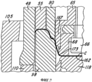
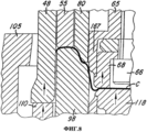
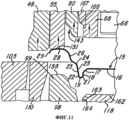
Как показано на Фигурах 4 и 5, центральный вставной резец штампа 68 имеет угловую поверхность 173 с большим радиусом, причем этот радиус больше, чем радиус изогнутой наружу поверхности 144 S-образной поверхности 143 на внутренней нажимной втулке 80. Вставной резец штампа 68 начинает вытягивание участка цилиндра С (Фигура 5) из центрального участка диска 170 в пределах внешней нажимной втулки 55 и кольцевого сердечника штампа 98. Внутренний свод 26 корпуса 15 формируется между поверхностями 147, 143 и 144 на внутренней нажимной втулке 80 и стыкуемыми поверхностями на кольцевом сердечнике штампа 98 (Фигура 5). Продолжение хода вниз верхней плиты штампа 40 вызывает взаимодействие вставного резца 68 центрального пробойника штампа 65 и находящегося под давлением панельного пробойника 118 с целью продолжения вытягивания участка цилиндра С, в то время как наружный участок диска 170 скользит между внешней нажимной втулкой 55, кольцевым сердечником штампа 95 и вырубным и вытяжным штампом 48. Как показано на Фигуре 7, продолжение хода вниз верхней плиты штампа 40 заставляет кольцевой участок юбки 167 центрального пробойника штампа 65 выдвигаться из внутренней нажимной втулки 80 вплоть до осуществления контакта фасонной торцевой поверхности 166 участка юбки 167 с поверхностями 158 и 161 с целью формирования наклонных участков 23 и 24, соединенных посредством небольшого углового изгиба 25. Одновременно нижние фасонные поверхности 143, 144 и 147 внутренней нажимной втулки 80 формируют и фиксируют промежуточный кольцевой участок диска 170 впритык к стыкуемым фасонным поверхностям 157, 156 и 154 кольцевого сердечника штампа 98, с целью формирования кольцевых участков 23, 24 и 26 (Фигура 11) корпуса 15. Свод 28 и участок внешнего фланца 29 корпуса 15 одновременно формируются на кольцевом сердечнике штампа 98 под действием регулируемого усилия на поршень 56 внешней нажимной втулки 55.As shown in Figures 4 and 5, the central
Когда верхняя плита штампа 40 пресса доходит вниз до нижней точки своего хода (Фигура 7), а поршень 56 останавливается на плече 90 центрального поршня штампа 60, то регулируемое давление воздуха внутри камеры 44 над центральным поршнем штампа 60 делает возможным передвижение указанного поршня 60 и центрального пробойника штампа 65 слегка вверх, приблизительно на 0,010 дюйма. В некоторых прессах это гарантирует, что общая высота всех готовых корпусов всегда является постоянной и одинаковой. В других более точно регулируемых прессах центральный поршень штампа может быть закреплен на фиксаторе 38 или 38'.When the upper plate of the press die 40 reaches down to the lower point of its stroke (Figure 7), and the piston 56 stops on the
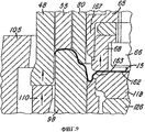
Когда верхняя плита штампа 40 начинает свой ход вверх (Фигура 8), центральный пробойник штампа 65 и расположенный напротив него нижний панельный пробойник 118 перемещаются вверх, в то время как внутренняя нажимная втулка 80 поддерживает регулируемое постоянное давление для того, чтобы удержать участки поршня 26 и 28 между стыкуемыми поверхностями на внутренней нажимной втулке 80 и кольцевом сердечнике штампа 98. Такое регулируемое давление внутренней нажимной втулки 80 поддерживается, пока панельный пробойник 118 движется вверх под действием силы, создаваемой поршнем панельного пробойника 122, так что периферийные поверхности 163, 164 и 165 образуют кольцевые участки 17, 18, 19 и 21 на указанном корпусе 15, как показано на Фигуре 10. По мере того как верхняя плита штампа 40 продолжает свой ход вверх, готовый корпус 15 сдвигается вверх с кольцевого сердечника штампа 98 и панельного пробойника 118 вместе с перемещением вверх внешней нажимной втулки 55 в результате выпуска потока воздуха, направляемого вверх на стенку панели 16 через отверстие 131 панельного пробойника 118.When the
Было установлено, что описываемые конструкция и функционирование инструментальной оснастки 35 или 35' обеспечивают важные и требуемые признаки и преимущества, приведенные выше на странице 1. Например, компактная инструментальная оснастка адаптирована для работы как на механическом прессе одинарного действия, так и на прессе двойного действия, а уменьшенная общая высота указанной оснастки делает возможным ее применение в большинстве существующих в настоящее время в этой области высокоскоростных прессов одинарного действия. Другим важным преимуществом является то, что камера-резервуар воздуха 70 и ряд расположенных по периферии воздушных амортизационных каналов 88 внутри центрального поршня штампа 60 обеспечивают использование более низкого давления воздуха в камере поршня 84, а более низкий уровень давления воздуха на поршень 82 внутренней нажимной втулки 80 уменьшает выработку тепла в верхней части инструментальной оснастки во время высокоскоростных операций, поэтому указанная инструментальная оснастка производит более однородные и точные корпуса.It has been found that the described construction and operation of the
Сжатый воздух внутри камеры воздуха 70 и \ или 91 и внутри каналов 88 и 88' также действует как воздушные амортизаторы. Эти воздушные амортизаторы не только снижают выработку тепла, но предназначены также для точного подбора упругого усилия, прилагаемого на поршень 82 внутренней нажимной втулки 80, для того, чтобы обеспечить требуемое точное усилие прижатия диска 170 внутренней нажимной втулкой 80 к зафиксированному кольцевому сердечнику штампа 98. Инструментальная оснастка 35 позволяет также осуществлять подачу воздуха более низкого давления (типа давления 70-90 фунтов/квадратный дюйм) на поршень 56 внешней нажимной втулки 55, а такое точно регулируемое пониженное давление воздуха на внешнюю нажимную втулку позволяет исключить растягивание металлического листа, так как указанный лист скользит между внешней нажимной втулкой 55, кольцевым сердечником штампа 98 и вытяжным и вырубным штампом в процессе формирования участка цилиндра С.Compressed air inside the air chamber 70 and / or 91 and inside the
Следующее преимущество обеспечивается за счет конструкции центрального пробойника штампа 65 и вставного резца 68, а также кольцевого сердечника штампа 98 и панельного пробойника 118. Например, функционирование и синхронность пресса при работе с фасонными поверхностями на нижнем конце внутренней нажимной втулки 80 и фасонными поверхностями на нижнем участке юбки 167 центрального пробойника штампа относительно соответствующих фасонных поверхностей на верхнем конце кольцевого сердечника штампа 98 и периферийных поверхностей на верхней части панельного пробойника 118 имеет результатом надежное производство корпуса 15 с очень равномерной толщиной стенки и без образования складок или трещин в листовом металле, из которого формируется корпус. Указанная инструментальная оснастка может также формировать корпус при более низком давлении воздуха, что помогает обеспечить более высокую силу стяжки корпуса. Например, давление воздуха в отверстии 92 (Фигура 1) может быть 70-90 фунтов/квадратный дюйм на поршень 56 внешней нажимной втулки 55, а давление воздуха в отверстии 92 (Фигура 2) для вытеснения внешней нажимной втулки и поршня 82 внутренней нажимной втулки 80 может составлять 110-130 фунтов/квадратный дюйм. Это преимущество более низкого давления имеет результатом более низкий нагрев, что особенно желательно при работе указанной инструментальной оснастки в прессе с высокой скоростью, типа 650 ходов в минуту с ходом, составляющим 1,75 дюйма. Кроме того, фасонные поверхности 166 на центральном пробойнике штампа 65 формируют наклонную стенку с точным небольшим угловым изгибом 25, что также увеличивает силу стяжки корпуса. Указанная инструментальная оснастка также обеспечивает формирование наклонной панельной стенки 17 (Фигуры 8 и 9) и фаски 19 в корпусе 15 без сжатия листового металла между штампами, так что эти участки корпуса имеют строго равномерную толщину и обеспечивают более равномерную силу стяжки.A further advantage is provided by the design of the central punch of the
Хотя описанные в данном документе устройство или инструментальная оснастка, а также способ их эксплуатации составляют предпочтительные варианты осуществления настоящего изобретения, следует понимать, что настоящее изобретение не ограничивается конкретной инструментальной оснасткой и описанными здесь стадиями способа, и что возможны изменения, сделанные без отступления от сущности и границ настоящего изобретения, и в той мере, в какой они соответствуют прилагаемой формуле изобретения.Although the device or tooling described herein, as well as the method of operation thereof, are preferred embodiments of the present invention, it should be understood that the present invention is not limited to the specific tooling and process steps described herein, and that changes are possible without departing from the gist and the boundaries of the present invention, and to the extent that they correspond to the attached claims.
Claims (7)
кольцевой вырубной и вытяжной штамп (48) и противоположно расположенную кольцевую первую нажимную втулку (110) для вырубания диска из листа металла,
кольцевую внешнюю нажимную втулку (55) внутри указанного вырубного и вытяжного штампа, а также противоположно расположенный кольцевой сердечник штампа (98) внутри указанной первой нажимной втулки,
внутреннюю нажимную втулку (80) внутри указанной внешней нажимной втулки и противоположно расположенный указанный кольцевой сердечник штампа,
центральный пробойник штампа (65) внутри указанной внутренней нажимной втулки, а также противоположно расположенный панельный пробойник (118) внутри указанного кольцевого сердечника штампа,
при этом указанная внутренняя нажимная втулка и указанный кольцевой сердечник штампа имеют противоположно расположенные и стыкуемые друг с другом фасонные поверхности (143, 154) для формирования внутренней наклонной стенки (26) свода,
указанный панельный пробойник (118) имеет кольцевые внешние фасонные поверхности (163-165), образующие указанную панельную стенку (17) и фаску (19) при осевом смещении указанного панельного пробойника (118) с указанным центральным пробойником штампа (65) в одном осевом направлении,
отличающееся тем, что
указанный центральный пробойник штампа (65) снабжен вставным резцом центрального пробойника штампа, имеющим радиус закругления вершины (173), распределенный по радиусу внутрь от внутренней поверхности указанной внутренней нажимной втулки (80) для задания кольцевого пространства,
при этом указанный центральный пробойник штампа (65) содержит кольцевой участок юбки (167), окружающий указанный вставной резец центрального пробойника штампа (68) и имеющий указанные фасонные внешние поверхности (166), выступающие внутрь указанного кольцевого пространства и стыкуемые с противоположно расположенными фасонными поверхностями (158, 161) на указанном кольцевом сердечнике штампа (98) для формирования указанной наклонной стенки (23, 24) при осевом смещении указанного центрального пробойника штампа в противоположном направлении.1. A device for forming a circular can body (15) having a cylinder shape from a flat sheet of metal in a mechanical press, said body comprising a central panel (16) connected via an annular panel wall (17) to an annular chamfer (19), usually having a U-shaped configuration in cross section, and through the chamfer attached to the annular arch (28) using an inclined annular wall (23, 24), containing:
an annular punch and exhaust stamp (48) and an oppositely disposed annular first push sleeve (110) for cutting a disc from a metal sheet,
an annular external pressure sleeve (55) inside the specified punch and exhaust stamp, as well as an oppositely arranged annular core of the stamp (98) inside the specified first pressure sleeve,
an internal pressure sleeve (80) inside said external pressure sleeve and an oppositely located indicated annular die core,
a central punch of the stamp (65) inside the specified inner pressure sleeve, as well as an oppositely located panel punch (118) inside the specified annular core of the stamp,
wherein said inner pressure sleeve and said annular die core have shaped surfaces (143, 154) oppositely located and joined together to form an inner inclined wall (26) of the arch,
the specified panel punch (118) has an annular outer shaped surface (163-165), forming the specified panel wall (17) and the chamfer (19) with axial displacement of the specified panel punch (118) with the specified Central punch stamp (65) in one axial direction ,
characterized in that
the specified Central punch of the stamp (65) is equipped with an insertion cutter of the Central punch of the stamp having a radius of curvature of the top (173), distributed along the radius inward from the inner surface of the specified inner pressure sleeve (80) to define the annular space,
wherein said central punch of the stamp (65) comprises an annular portion of the skirt (167) surrounding said insert cutter of the central punch of the stamp (68) and having said shaped outer surfaces (166) protruding inside said annular space and mating with opposed shaped surfaces ( 158, 161) on the indicated annular core of the stamp (98) for the formation of the specified inclined wall (23, 24) with axial displacement of the specified Central punch stamp in the opposite direction.
вырезку заготовки диска из листа,
зажим кольцевого участка указанного диска с регулируемым давлением между кольцевым сердечником штампа и противоположной кольцевой внешней нажимной втулкой,
вытягивание цилиндра из центрального участка диска с помощью центрального пробойника штампа до прижима внутренней нажимной втулкой наклонного кольцевого участка цилиндра к кольцевому сердечнику штампа и формирования наклонной внутренней стенки для кольцевого свода, отличающийся тем, что
осуществляют инициирование вытягивания цилиндра из центрального участка диска с помощью вставного резца внутри кольцевого участка юбки центрального пробойника штампа, расположенного внутри кольцевой внутренней нажимной втулки, причем
продолжение вытягивания указанного цилиндра осуществляют посредством взаимодействия вставного резца центрального пробойника штампа с противоположным панельным пробойником для завершения формирования цилиндра одновременно со стыковкой фасонной внешней поверхности на участке юбки центрального пробойника штампа с фасонной внутренней поверхностью на кольцевом сердечнике штампа для формирования кольцевой наклонной стенки корпуса, и
осуществление перемещения указанного панельного пробойника и центрального пробойника штампа при продолжении зажима кольцевого участка цилиндра между внутренней нажимной втулкой и кольцевым сердечником штампа для формирования центральной панели и панельной стенки, а также фаски с поверхностями на периферийном участке панельного пробойника.6. A method of forming a circular shape of a cylinder-shaped tin can from a flat sheet of metal in a mechanical press, said casing comprising a central panel connected by an annular panel wall with an annular chamfer, usually having a U-shape in cross section, and through said a chamfer attached to the annular vault using an inclined annular wall, comprising the following stages:
cutting a disk blank from a sheet,
clamping an annular portion of said pressure-adjustable disk between the annular core of the stamp and the opposite annular external push sleeve,
pulling the cylinder from the central portion of the disc using the central punch of the stamp to the clip the inner pressure sleeve of the inclined annular portion of the cylinder to the annular core of the stamp and the formation of the inclined inner wall for the annular arch, characterized in that
initiating the pulling of the cylinder from the central portion of the disk with the insert cutter inside the annular portion of the skirt of the central punch of the stamp located inside the annular inner pressure sleeve,
continued drawing of said cylinder carried out by the interaction of the insert cutter of the Central punch stamp with the opposite panel punch for completing the formation of the cylinder simultaneously with the fitting of the shaped external surface on the skirt section of the central punch of the stamp with the shaped inner surface on the annular core of the stamp to form an annular inclined wall of the body, and
the implementation of the movement of the specified panel punch and the central punch of the stamp while continuing to clamp the annular portion of the cylinder between the inner pressure sleeve and the annular core of the stamp to form the central panel and the panel wall, as well as the bevel with surfaces on the peripheral portion of the panel punch.
Applications Claiming Priority (3)
| Application Number | Priority Date | Filing Date | Title |
|---|---|---|---|
| US12/924,077 US8573020B2 (en) | 2010-09-20 | 2010-09-20 | Method and apparatus for forming a can shell |
| US12/924,077 | 2010-09-20 | ||
| PCT/US2011/001590 WO2012039747A2 (en) | 2010-09-20 | 2011-09-15 | Method and apparatus for forming a can shell |
Publications (2)
| Publication Number | Publication Date |
|---|---|
| RU2013111458A RU2013111458A (en) | 2014-10-27 |
| RU2575889C2 true RU2575889C2 (en) | 2016-02-20 |
Family
ID=
Citations (3)
| Publication number | Priority date | Publication date | Assignee | Title |
|---|---|---|---|---|
| SU1722656A1 (en) * | 1989-10-30 | 1992-03-30 | Краматорский Индустриальный Институт | Method of making hollow articles |
| RU94045276A (en) * | 1993-01-29 | 1997-02-27 | МН Машиненбау унд Инжиниринг Мартин Нуссбаум (CH) | Method of making aluminium cans for drink and food and plant for performing the same |
| RU2211107C2 (en) * | 1998-03-04 | 2003-08-27 | Корус Стал Б.В. | Method for making preserve cans by thinning walls |
Patent Citations (3)
| Publication number | Priority date | Publication date | Assignee | Title |
|---|---|---|---|---|
| SU1722656A1 (en) * | 1989-10-30 | 1992-03-30 | Краматорский Индустриальный Институт | Method of making hollow articles |
| RU94045276A (en) * | 1993-01-29 | 1997-02-27 | МН Машиненбау унд Инжиниринг Мартин Нуссбаум (CH) | Method of making aluminium cans for drink and food and plant for performing the same |
| RU2211107C2 (en) * | 1998-03-04 | 2003-08-27 | Корус Стал Б.В. | Method for making preserve cans by thinning walls |
Similar Documents
| Publication | Publication Date | Title |
|---|---|---|
| RU2506137C2 (en) | Method and device for forming can body | |
| EP2618952B1 (en) | Method and apparatus for forming a can shell | |
| CN105750403A (en) | Fixing piece side face punching die | |
| RU2575889C2 (en) | Method and device for can body forming | |
| JP2004141883A (en) | Double-acting forging method and apparatus | |
| CN216729186U (en) | Steel cylinder stamping necking die | |
| US7240531B2 (en) | Press for forming containers with profiled bottoms | |
| CN216632335U (en) | Workpiece supporting structure of stamping necking die | |
| CN216656023U (en) | Die for gasket production | |
| CN104096963A (en) | Clamping and positioning method for friction welding of steel piston | |
| CN102773349A (en) | Forming mould and method for preparing Z-shaped ring body by using same | |
| RU2229356C2 (en) | Apparatus for forming bellows | |
| RU2240887C1 (en) | Part blanking, drawing and trimming apparatus | |
| CN115007710A (en) | Mechanism for pressing marks on pipe wall of steel pipe | |
| CN105268820A (en) | Large-caliber hydraulically-controlled type tee joint pipe buckle type rigid and plastic composite bulging forming device | |
| CN105290195A (en) | Locking rigid-plastic compound bulging forming apparatus for large-caliber three-way pipes |