RU2585103C1 - Extended mine clearing charge - Google Patents
Extended mine clearing charge Download PDFInfo
- Publication number
- RU2585103C1 RU2585103C1 RU2014151511/11A RU2014151511A RU2585103C1 RU 2585103 C1 RU2585103 C1 RU 2585103C1 RU 2014151511/11 A RU2014151511/11 A RU 2014151511/11A RU 2014151511 A RU2014151511 A RU 2014151511A RU 2585103 C1 RU2585103 C1 RU 2585103C1
- Authority
- RU
- Russia
- Prior art keywords
- rings
- sections
- grooves
- section
- elongated
- Prior art date
Links
Images
Classifications
-
- F—MECHANICAL ENGINEERING; LIGHTING; HEATING; WEAPONS; BLASTING
- F42—AMMUNITION; BLASTING
- F42B—EXPLOSIVE CHARGES, e.g. FOR BLASTING, FIREWORKS, AMMUNITION
- F42B3/00—Blasting cartridges, i.e. case and explosive
- F42B3/02—Blasting cartridges, i.e. case and explosive adapted to be united into assemblies
Landscapes
- Engineering & Computer Science (AREA)
- General Engineering & Computer Science (AREA)
- Portable Nailing Machines And Staplers (AREA)
Abstract
Description
Предлагаемое изобретение относится к области военной техники, а именно к устройствам удлиненных зарядов разминирования, подаваемых из наземных пусковых установок на противотанковые минные поля по воздуху реактивными двигателями для проделывания в минных полях проходов для бронемашин и другой техники в ходе быстротечной наступательной операции.The present invention relates to the field of military equipment, namely, devices of elongated clearance charges supplied from land launchers to anti-tank mine fields through the air by jet engines to make passages for armored vehicles and other equipment in mine fields during a quick offensive operation.
Из уровня техники известны удлиненные заряды разминирования, входящие в боекомплекты установок разминирования «УР-83П», «УР-77» (прототип) (Россия) (см., например, "Оружие России"/ Каталог/ Т.УН/ "Высокоточное оружие и боеприпасы"/ АОЗТ "Военный парад", стр. 657, 658. М. - 1997), «TAMKAR» (Турция) (см., например, "Jane's Mines and Mine Clearance 2008-2009"/ Edited by Colin King/ Thirteenth Edition, стр. 715), «М58 (M58 MICLIC)» (США) (см., например, Полевой Устав армии США FM 20-32. Mine/Contermine Operations. Headquarters, Department of the Army, Washington, DC, 30 June 1999. Change 22.08.2001. Chapter 10).From the prior art, elongated clearance charges are known that are part of the ammunition of the UR-83P and UR-77 demining systems (prototype) (Russia) (see, for example, Russia's Arms / Catalog / T.UN / High-precision weapons and ammunition "/ AOZT" Military Parade ", p. 657, 658. M. - 1997)," TAMKAR "(Turkey) (see, for example," Jane's Mines and Mine Clearance 2008-2009 "/ Edited by Colin King / Thirteenth Edition, p. 715), “M58 (M58 MICLIC)” (USA) (see, for example, US Army Field Charter FM 20-32. Mine / Contermine Operations. Headquarters, Department of the Army, Washington, DC, 30 June 1999. Change 08/22/2001. Chapter 10).
Известные заряды разминирования имеют длину до нескольких сотен метров и массу в несколько тонн и по условиям производства и эксплуатации состоят из последовательно собираемых между собой методом свинчивания длинных секций массой в несколько десятков килограммов. При этом каждая секция содержит звенья зарядов взрывчатого вещества (ВВ), каждый из которых находится во внешней оболочке или в корпусе, сквозные силовые нити, воспринимающие основные продольные нагрузки реактивной подачи, сквозные шнуры передачи детонации, узлы сгиба секции между звеньями, концевые узлы заделки силовых нитей, передачи детонации и соединения секций. Концевые узлы содержат снаряженный передаточным зарядом-детонатором металлический концевой штуцер.Known clearance charges have a length of up to several hundred meters and a mass of several tons and, according to the conditions of production and operation, consist of successively assembled long sections weighing several tens of kilograms between each other by screwing. In this case, each section contains links of explosive charges (BB), each of which is located in the outer shell or in the case, through power threads that absorb the main longitudinal loads of the reactive feed, through detonation transmission cords, section bend nodes between the links, end knots for terminating power threads, knocking and joining sections. The end nodes contain a metal end fitting equipped with a transfer charge detonator.
Все известные авторам отечественные и зарубежные удлиненные заряды разминирования имеют резьбовые узлы последовательного соединения секций, соответственно выполненные по-разному - с внутренней резьбой на хвостовом штуцере, (так как это - сторона установки взрывателя) и наружной резьбой на головном штуцере. Соответственно, отличаются конструктивно и многие смежные детали. В производстве зарядов разминирования это повышает номенклатуру металлокомплекта и, в конечном счете, его себестоимость.All domestic and foreign elongated clearance charges known to the authors have threaded units for connecting sections in series, respectively, made differently with internal threads on the tail nipple (since this is the fuse mounting side) and external threads on the head nipple. Accordingly, many related parts are structurally different. In the production of clearance charges, this increases the nomenclature of the metal kit and, ultimately, its cost.
При снаряжении и перезарядке установок разминирования заряды последовательно собираются из секций, которые извлекаются из упаковок, подаются боевым расчетом в удлиненные кассеты на борту установки, последовательно присоединяются и компактно укладываются за счет формируемых сгибов. Стыковку очередной секций зачастую предпочитают производить уже внутри кассеты по завершении укладки в ней предыдущей секции (особенно при минусовой температуре). При этом в кассете может свободно действовать только один боец, он же и укладывает и свинчивает секции. Все операции производятся вручную, трудоемки, занимают много времени и для боевого расчета регламентируются нормативным временем сборки и загрузки заряда разминирования в установку разминирования.When equipping and reloading demining systems, charges are sequentially collected from sections that are removed from the packages, delivered by combat crew to elongated cartridges on board the unit, sequentially attached and compactly stacked due to the formed folds. Docking of the next sections is often preferred to be done already inside the cassette upon completion of laying the previous section in it (especially at sub-zero temperatures). In this case, only one fighter can freely act in the cassette, he also stacks and makes sections. All operations are manual, time-consuming, time-consuming and, for combat crew, are regulated by the standard assembly time and loading of the clearance charge into the clearance unit.
Перед разработчиками этого вида вооружения стоит задача постоянного его совершенствования в направлении улучшения основных тактико-технических характеристик, к которым относится, с одной стороны, погонная масса ВВ и длина заряда разминирования, определяющие эффективность действия, а с другой стороны - удобство и скорость перезаряжания установки ее боевым расчетом.The developers of this type of weapon are faced with the task of constantly improving it in the direction of improving the main tactical and technical characteristics, which include, on the one hand, the linear mass of explosives and the length of the mine clearance, which determine the effectiveness of the action, and on the other hand, the convenience and speed of reloading its installation combat crew.
При увеличении длины и массы заряда удобство и скорость перезарядки машины становится едва ли не главным эксплуатационным параметром. Ведь проделывание проходов взрывным способом осуществляется в ходе быстротечной наступательной операции, а перезарядка подвижной установки разминирования после очередного применения не может проводиться на ходу, как, например, загрузка грузовой автомашины, и установка на время перезарядки отстает от переднего края фронта, вблизи которого она наготове должна находиться. Поэтому при проведении учебной боеподготовки расчеты отрабатывают сборочные операции, стараясь сократить время перезарядки до минимума.With an increase in the length and mass of the charge, the convenience and speed of recharging the machine becomes almost the main operational parameter. Indeed, the passage of explosive passes is carried out during a quick offensive operation, and reloading of a moving mine clearance unit after the next application cannot be carried out on the go, such as loading a truck, and the installation is recharging behind the front edge of the front, near which it should be ready at the time of reloading be. Therefore, when conducting training combat training, the calculations work out assembly operations, trying to reduce the reload time to a minimum.
Известные заряды разминирования в последние десятилетия изготавливались из пластических ВВ. В настоящее время технологические возможности формования удлиненных зарядов из пластических ВВ, тем более с увеличением их погонной массы, фактически исчерпаны. Зато по-новому открылись перспективы использования более мощных и в нынешних условиях технологически обеспеченных литьевых взрывчатых композиций. Поэтому новые конструкции зарядов разминирования возвратились к схемам многозвенных секций с жесткими корпусными или шашечными звеньями ВВ, т.е. с расчлененной по длине секции погонной массой заряда ВВ.Known clearance charges in recent decades have been made from plastic explosives. Currently, the technological capabilities of forming elongated charges from plastic explosives, especially with an increase in their linear mass, are practically exhausted. But in a new perspective opened up the use of more powerful and in the current conditions technologically advanced injection-molded explosive compositions. Therefore, the new design of mine clearance charges returned to the schemes of multi-link sections with rigid hull or checkered explosive links, i.e. with the linear mass of explosive charge divided along the section length.
Однако, если благодаря податливости, мягкости пластического заряда подача удлиненного заряда разминирования по воздуху происходит в относительно щадящем режиме, то при подаче удлиненного заряда с «расчлененной» погонной массой имеют место существенно большие, рывково-неравномерные нагрузки: поперечные, во время выборки из кассеты, и продольные, в полете и при финальном торможении. Данная специфика многозвенных конструкций требует соответствующего конструктивного решения в направлении повышения прочности соединительных узлов.However, if due to the flexibility and softness of the plastic charge, the elongated mine clearance charge is supplied in air in a relatively sparing mode, then when the elongated charge is supplied with a “dissected” linear mass, significantly larger, jerky-uneven loads occur: transverse, during sampling from the cartridge, and longitudinal, in flight and during final braking. This specificity of multi-link structures requires an appropriate design solution in the direction of increasing the strength of the connecting nodes.
Неизменно актуальными остаются и технологические задачи по снижению трудоемкости изготовления и стоимости всех компонентов заряда разминирования.Technological tasks to reduce the complexity of manufacturing and the cost of all components of the clearance charge remain invariably relevant.
Задачей предлагаемого изобретения является создание удлиненного заряда разминирования, лишенного вышеуказанных недостатков.The objective of the invention is the creation of an elongated mine clearance devoid of the above disadvantages.
Предлагаемое изобретение обеспечивает следующие технические результаты:The invention provides the following technical results:
- снижение времени сборки и загрузки заряда разминирования в установку разминирования (до 40%) и снижение трудоемкости сборочных операций боевому расчету в полевых условиях, особенно при отрицательных температурах;- reduction of the assembly time and loading of the mine clearance charge into the mine clearance facility (up to 40%) and reduction of the laboriousness of assembly operations to combat crew in the field, especially at low temperatures;
- повышение функциональных характеристик присоединительных узлов заряда разминирования и снижение рывково-неравномерных нагрузок на элементы секций при пуске заряда разминирования;- improving the functional characteristics of the connecting nodes of the mine clearance charge and reducing jerky-uneven loads on the elements of the sections when starting the mine clearance charge;
- повышение технологических и снижение стоимостных показателей конструктивного решения за счет уменьшения номенклатуры деталей концевых элементов секций, простоты и технологичности изготавливаемых деталей.- increasing technological and reducing the cost of structural solutions by reducing the range of parts of the end elements of the sections, the simplicity and manufacturability of the manufactured parts.
Разработанный авторами удлиненный заряд разминирования состоит из секций, каждая из которых содержит удлиненные заряды взрывчатого вещества, узлы сгибов, а также концевые узлы соединения и передачи детонации, содержащие, каждый, концевой штуцер, отличающийся тем, что каждая секция выполнена с одинаковыми концевыми штуцерами, выполненными с цилиндрическими концами, а удлиненный заряд разминирования снабжен охватывающими концы штуцеров муфтами сцепления секций с замками на основе разрезных пружинных колец ромбоидального сечения и кольцевых канавок, при этом донные и заходные поверхности канавок на муфтах и штуцерах и все торцевые и боковые поверхности колец выполнены коническими, сходящимися к смежной секции, а сами кольца выполнены с обеспечением возможности скручивания и заклинивания в канавках при растягивающей силовой нагрузке.The elongated mine clearance developed by the authors consists of sections, each of which contains elongated explosive charges, bend nodes, as well as end knots for connecting and transmitting detonation, each containing an end fitting, characterized in that each section is made with the same end fittings made with cylindrical ends, and the elongated clearance charge is equipped with clutch sections of the sections with locks covering the ends of the fittings based on split spring rings of rhomboidal section and count tsevyh grooves, and bottom surfaces of the grooves on zahodnye couplings and fittings, and all the end and side surfaces of the rings are conical, converging towards the adjacent section, and the rings is configured to twisting and jamming in the grooves when a tensile force load.
Углы конусности составляют 150…165° для противоположных торцевых поверхностей колец, 30…60° для противоположных боковых поверхностей колец и донных поверхностей канавок штуцеров и муфт, а сечение колец выполнено с двойным и более удлинением.The taper angles are 150 ... 165 ° for the opposite end surfaces of the rings, 30 ... 60 ° for the opposite side surfaces of the rings and the bottom surfaces of the grooves of the fittings and couplings, and the section of the rings is made with double or more elongation.
Разрезные кольца выполнены с ослабляющими поперечными вырезами, а число пар кольцо-канавка в каждой муфте может составлять не менее четырех.Split rings are made with attenuating transverse cuts, and the number of ring-groove pairs in each coupling can be at least four.
Муфты могут быть снабжены прорезями по месту прогалов разрезных колец для введения разжимных щипцов.The couplings may be provided with slots at the points of the spans of the split rings for introducing expanding tongs.
Такое выполнение конструкции удлиненного заряда разминирования обеспечивает существенное снижение времени перезарядки установки разминирования и облегчение работ боевому расчету. Оно обеспечивает также повышение прочностных и функциональных характеристик присоединительных узлов заряда, повышение технологических и снижение стоимостных показателей разработанного технического решения.This embodiment of the design of the elongated mine clearance charge provides a significant reduction in the reloading time of the mine clearance unit and facilitates combat crew work. It also provides an increase in the strength and functional characteristics of the connecting charge nodes, an increase in technological and a decrease in the cost indicators of the developed technical solution.
Конструкцию предлагаемого удлиненного заряда разминирования иллюстрируют чертежи и фотографии.The design of the proposed extended charge clearance is illustrated by drawings and photographs.
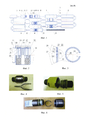
На Фиг. 1 показан общий вид удлиненного заряда разминирования в частично собранном виде, в процессе его подачи в кассету установки и перед окончательной сборкой с использованием очередной соединительной муфты.In FIG. 1 shows a general view of an elongated mine clearance charge in a partially assembled form, in the process of feeding it to the installation cassette and before final assembly using the next coupler.
На Фиг. 2 показан в разрезе узел соединения секций удлиненного заряда разминирования.In FIG. 2 shows a sectional view of an assembly for connecting sections of an elongated clearance charge.
На Фиг. 3 показана геометрия одного из пружинных колец муфты.In FIG. 3 shows the geometry of one of the coupling spring rings.
На Фиг. 4, 5, 6 представлены фотографии вариантов узлов соединения до и после проведенных испытаний на растяжение до разрушения.In FIG. 4, 5, 6, photographs of options for connection points are presented before and after the tensile tests to failure.
Как и все известные удлиненные заряды разминирования, разработанный удлиненный заряд разминирования (Фиг. 1) содержит последовательно соединяемые секции. Секции содержат удлиненные звенья 1, 2 заряда взрывчатого вещества в корпусной или оплеточной оболочке, узлы сгибов 3 между всеми звеньями 1, 2, сквозные шнуры передачи детонации 4, сквозные силовые нити 5, а также концевые головные 6 и хвостовые 7 узлы заделки силовых нитей, соединения секций и передачи детонации. Концевые узлы содержат снаряженные передаточными зарядами-детонаторами концевые штуцеры - головные концевые штуцеры 8 и хвостовые концевые штуцеры 9.Like all known elongated clearance charges, the developed elongated clearance charge (Fig. 1) contains sections connected in series. The sections contain
В разработанной конструкции каждая секция выполнена симметричной - с одинаковыми по конструкции головными 8 и хвостовыми 9 штуцерами, при этом штуцеры 8, 9 выполнены с цилиндрическими по форме концами 10 и 11 (Фиг. 2). Заряд разминирования снабжен охватывающими концы штуцеров (надеваемыми на концы штуцеров) соединительными муфтами 12 сцепления секций (Фиг. 1, Фиг. 2) с замками на основе (Фиг. 2, Фиг. 3) пружинных разрезных колец 13, кольцевых канавок 14 на внутренней стороне муфты 12 и ответных кольцевых канавок 15 на цилиндрических концах 10, 11 смежных штуцеров 8, 9.In the developed design, each section is symmetrical - with the
Кольца 13 выполнены ромбоидального сечения, при этом донные 16 поверхности канавок на муфтах, заходные 17 (на конце) и 18 (внутри) поверхности на муфтах, донные поверхности 19 канавок 15 на штуцерах, заходные поверхности 20 на штуцерах (Фиг. 3) и все торцевые 21, 22, боковые 23 и 24 поверхности колец выполнены коническими. Эти конические поверхности соответствующих замковых пар сходятся к смежной секции (вершины конических поверхностей каждой замковой пары направлены в сторону соответствующей присоединяемой секции).The
При этом кольца 13 выполнены с обеспечением возможности скручивания и заклинивания в канавках 14 при растягивающей силовой нагрузке.When this
Углы конусности 25 и 26 (Фиг. 3) колец 13 для противоположных торцевых поверхностей 21 и 22 составляют 150…165°. Углы конусности 27 и 28 для противоположных боковых поверхностей 23 и 24 колец 13, а также углы конусности для донных поверхностей 16 канавок 14 на муфтах 12, и также углы конусности донных поверхностей 19 канавок 15 на штуцерах выбраны в пределах 30…60°. Сечение колец выполнено с двойным и более удлинением. Данные соотношения получены в результате расчетной и конструкторской проработки. При уменьшении угла 30° резко увеличивается длина колец и снижается их устойчивость, а при увеличении угла 60° значительно увеличивается жесткость колец.The
Кольца 13 преимущественно в средней части относительно прорези 29 выполнены с ослабляющими поперечными вырезами 30.The
В каждой муфте может быть выполнено только две замковые пары, то есть по одному кольцу на сторону. Однако, как будет отмечено ниже, число замковых пар целесообразно иметь не менее четырех, то есть, по меньшей мере, по два кольца на сторону.In each coupling, only two lock pairs can be made, that is, one ring per side. However, as will be noted below, it is advisable to have the number of lock pairs at least four, that is, at least two rings per side.
Основное - боевое - исполнение удлиненного заряда разминирования, уложенного в кассету установки разминирования, никогда не предусматривает необходимость разборки по секциям. Как обычный боеприпас он рассчитан на однократное применение. В нештатной же ситуации, например, при повреждении установки заряд будет перегружен без разборки, к примеру, в кузов автомашины.The main - combat - execution of an elongated clearance charge laid in a mine clearance cassette never involves the need for disassembly in sections. Like regular ammunition, it is designed for single use. In an emergency situation, for example, if the installation is damaged, the charge will be overloaded without disassembling, for example, in the car body.
Учебное исполнение инертного заряда разминирования предусматривает его использование с выстрелами на дистанцию до десяти раз. После учебного выстрела также не предусмотрена разборка инертного заряда на секции. Заряд, как и положено, выдерживает тренировочные выстрелы и его с грунта подбирают и размещают обратно в кассету установки разминирования. Возможно, однако, и случайное повреждение инертного заряда, когда может понадобиться замена какой-нибудь секции. Известные резьбовые узлы соединения далеко не всегда позволяют это сделать из-за деформаций резьбовых деталей при пусках и падениях и из-за засорения и заклинивания резьбы.The training performance of the inert charge of mine clearance provides for its use with shots at a distance of up to ten times. After the training shot, the disassembly of the inert charge into sections is also not provided. The charge, as expected, withstands training shots and is picked up from the ground and placed back into the mine clearance cassette. It is possible, however, and accidental damage to the inert charge, when it may be necessary to replace any section. Known threaded connection nodes do not always allow this to be done due to deformation of threaded parts during starts and falls and due to clogging and jamming of the thread.
В предлагаемой конструкции на боковой поверхности муфт учебных (инертных) удлиненных зарядов разминирования предусмотрены показанные на Фиг. 2 щелевые прорези 31 под разжимной инструмент по месту прогалов (прорезей 29) разрезных пружинных колец.In the proposed construction, on the lateral surface of the training (inert) elongated clearance charges, shown in FIG. 2 slotted
Описанное конусное выполнение поверхностей колец и канавок, удлиненная форма сечения, уменьшающая толщину кольца, ослабляющие вырезы на кольцах и их дублирование для большего снижения приходящегося на каждое кольцо необходимого стыковочного усилия обеспечивают возможность ручной сборки без использования специального инструмента, всегда неудобного для войскового применения.The described conical execution of the surfaces of the rings and grooves, an elongated sectional shape, reducing the thickness of the ring, weakening the cutouts on the rings and their duplication to further reduce the necessary connecting force per ring, provide the possibility of manual assembly without the use of special tools that are always inconvenient for military use.
При снаряжении установки разминирования удлиненным зарядом разминирования секции изымаются из упаковок (в ящике - 1 секция и 1 отдельная муфта с установленными кольцами) и подаются расчетом к борту установки. В то время как любой ближайший к машине конец секции, как головной, направляется в кассету установки для подсоединения к реактивным двигателям подачи заряда, на хвостовой концевой штуцер 9 первый боец накидывает муфту 12, а второй боец расчета направляет к муфте ближайший штуцер 8 второй секции. Встречным силовым движением оба бойца сдвигают в муфте хвостовой и головной концевые узлы 7 и 6 соединяемых секций до упора и защелкивания на штуцерах разрезных пружинных колец. Вслед за первой вторая присоединенная секция и так же все последующие подаются расчетом на борт и последовательно укладываются в кассету установки разминирования. К концевой муфте или переходнику присоединяется взрывательное устройство 32 и тормозной канат 33, предназначенный для обеспечения заданной дистанции подачи и электрического или механического подрыва заряда.When the mine installation equipment is equipped with an extended mine clearance charge, the sections are removed from the packages (in the box - 1 section and 1 separate coupling with rings installed) and are delivered by calculation to the installation board. While any end of the section closest to the machine, like the head, is sent to the installation cassette for connection to the jet engines of charge supply, the first fighter puts the
Соединение с использованием разрезных колец значительно упрощает не только процесс стыковки секций, но и процесс укладки заряда в кассете, при котором возникающее из-за постоянного изменения плоскостей сгибов перекручивание заряда легко отыгрывается на стыках секций в муфтах 12, действующих как вертлюги.The connection using split rings greatly simplifies not only the joining of the sections, but also the process of stacking the charge in the cassette, in which the twisting of the charge due to the constant change in the plane of the bends easily plays out at the joints of the sections in the
При реактивной подаче удлиненного заряда на минное поле по воздуху последовательное вовлечение секций в движение имеет рывковый характер. Под действием боковых рывков и при выпрямлении ранее сложенных секций происходит скручивание нити заряда, аналогичное тому, как это происходило при укладке секции в кассету. И так же, как это обеспечивалось при укладке, прокручивание напряженных частей секций в местах соединений секций по муфтам 12 поддерживает целостность конструкции.When reactively feeding an elongated charge to a minefield through the air, the successive involvement of the sections in the movement is jerky. Under the action of lateral jerks and during straightening of previously folded sections, the charge filament twists, similar to how it happened when laying the section in a cassette. And just as this was ensured during installation, the scrolling of the stressed sections at the joints of the sections along the
При возрастании тяговой или тормозной нагрузок до пиковых значений и при многократных пульсациях продольной нагрузки кольца 13, упираясь острыми кромками поверхностей 21 и 22 в торцевые поверхности рабочих канавок муфт и штуцеров, подвергаются благодаря упругости и податливости скручиванию и соответствующему развороту сечений колец в канавках вплоть до заклинивания в противоположных углах противостоящих канавок муфт и концевых штуцеров, действуя при этом как амортизирующие прокладки. При этом благодаря конической форме торцевых поверхностей 21 и 22 и углам конусности 25 и 26, равным 150…165°, двойному и более удлинению сечения, при скручивании (вывертывании) колец их упорные кромки и торцевые упорные поверхности остаются в состоянии «скольжения» в глубь, а не из канавок и не могут выходить из зацеплений.With an increase in traction or brake loads to peak values and with repeated ripples of the longitudinal load of the
В заклиненном в углах канавок положении разрезные кольца обладают повышенной устойчивостью и соответственно прочностью на сжатие и поэтому в сечении могут быть выполнены более чем с двукратным удлинением. С другой стороны, для разрезных пружинных колец с более удлиненными сечениями (другими словами - с более тонкими сечениями) требуются меньшие разводные усилия, а это одно из условий для обеспечения возможности полевой сборки зарядов без применения специнструмента.In the position wedged in the corners of the grooves, the split rings have increased stability and, accordingly, compressive strength, and therefore can be made in section with more than double elongation. On the other hand, for split spring rings with longer sections (in other words, with thinner sections), less diverging efforts are required, and this is one of the conditions for enabling field assembly of charges without the use of a special tool.
Лабораторные испытания на растяжение подтвердили надежность, быстроту сборки и достаточную прочность соединений. В частности, прочность узла соединения, выполненного в габаритах серийного изделия, составила 10500 кг, что превышает существующую прочность почти вдвое.Laboratory tensile tests confirmed the reliability, speed of assembly and sufficient strength of the joints. In particular, the strength of the joint assembly made in the dimensions of the serial product amounted to 10,500 kg, which exceeds the existing strength by almost half.
Claims (5)
Priority Applications (1)
| Application Number | Priority Date | Filing Date | Title |
|---|---|---|---|
| RU2014151511/11A RU2585103C1 (en) | 2014-12-18 | 2014-12-18 | Extended mine clearing charge |
Applications Claiming Priority (1)
| Application Number | Priority Date | Filing Date | Title |
|---|---|---|---|
| RU2014151511/11A RU2585103C1 (en) | 2014-12-18 | 2014-12-18 | Extended mine clearing charge |
Publications (1)
| Publication Number | Publication Date |
|---|---|
| RU2585103C1 true RU2585103C1 (en) | 2016-05-27 |
Family
ID=56095932
Family Applications (1)
| Application Number | Title | Priority Date | Filing Date |
|---|---|---|---|
| RU2014151511/11A RU2585103C1 (en) | 2014-12-18 | 2014-12-18 | Extended mine clearing charge |
Country Status (1)
| Country | Link |
|---|---|
| RU (1) | RU2585103C1 (en) |
Cited By (6)
| Publication number | Priority date | Publication date | Assignee | Title |
|---|---|---|---|---|
| RU196269U1 (en) * | 2019-12-05 | 2020-02-21 | Федеральное государственное бюджетное учреждение "Центральный научно-исследовательский испытательный институт инженерных войск имени Героя Советского Союза генерал-лейтенанта инженерных войск Д.М. Карбышева" Министерства обороны Российской Федерации | An extended clearance charge placed in a rocket of a multiple launch rocket system |
| RU201313U1 (en) * | 2020-06-25 | 2020-12-09 | Федеральное государственное бюджетное учреждение "Центральный научно-исследовательский испытательный институт инженерных войск имени Героя Советского Союза генерал-лейтенанта инженерных войск Д.М. Карбышева" Министерства обороны Российской Федерации | Extended demining charge |
| RU202089U1 (en) * | 2020-07-08 | 2021-01-29 | Федеральное государственное бюджетное учреждение "Центральный научно-исследовательский испытательный институт инженерных войск имени Героя Советского Союза генерал-лейтенанта инженерных войск Д.М. Карбышева" Министерства обороны Российской Федерации | Spiral charge for making breaks in building elements |
| RU2743468C1 (en) * | 2020-07-10 | 2021-02-18 | Акционерное общество "Научно-исследовательский инженерный институт" (АО "НИИИ") | Mine-clearing line charge unit |
| RU203752U1 (en) * | 2020-09-21 | 2021-04-20 | Илья Евгеньевич Лентарев | Marine mesh charge demining |
| RU2813285C1 (en) * | 2023-08-24 | 2024-02-09 | Федеральное государственное казенное военное образовательное учреждение высшего образования "ВОЕННАЯ АКАДЕМИЯ МАТЕРИАЛЬНО-ТЕХНИЧЕСКОГО ОБЕСПЕЧЕНИЯ имени генерала армии А.В. Хрулева" | Combat arrow-shaped element for destruction of mine explosive devices |
Citations (3)
| Publication number | Priority date | Publication date | Assignee | Title |
|---|---|---|---|---|
| RU2045745C1 (en) * | 1992-06-16 | 1995-10-10 | Маринин Вячеслав Михайлович | Method of explosive destruction of large-sized blocks and shaped charge |
| WO2001025717A1 (en) * | 1999-10-01 | 2001-04-12 | Kevin Mark Powell | Hollow charge explosive device particularly for avalanche control |
| US8006621B1 (en) * | 2008-02-07 | 2011-08-30 | Cherry Christopher R | Linear explosive breaching apparatus and method |
-
2014
- 2014-12-18 RU RU2014151511/11A patent/RU2585103C1/en not_active IP Right Cessation
Patent Citations (3)
| Publication number | Priority date | Publication date | Assignee | Title |
|---|---|---|---|---|
| RU2045745C1 (en) * | 1992-06-16 | 1995-10-10 | Маринин Вячеслав Михайлович | Method of explosive destruction of large-sized blocks and shaped charge |
| WO2001025717A1 (en) * | 1999-10-01 | 2001-04-12 | Kevin Mark Powell | Hollow charge explosive device particularly for avalanche control |
| US8006621B1 (en) * | 2008-02-07 | 2011-08-30 | Cherry Christopher R | Linear explosive breaching apparatus and method |
Cited By (6)
| Publication number | Priority date | Publication date | Assignee | Title |
|---|---|---|---|---|
| RU196269U1 (en) * | 2019-12-05 | 2020-02-21 | Федеральное государственное бюджетное учреждение "Центральный научно-исследовательский испытательный институт инженерных войск имени Героя Советского Союза генерал-лейтенанта инженерных войск Д.М. Карбышева" Министерства обороны Российской Федерации | An extended clearance charge placed in a rocket of a multiple launch rocket system |
| RU201313U1 (en) * | 2020-06-25 | 2020-12-09 | Федеральное государственное бюджетное учреждение "Центральный научно-исследовательский испытательный институт инженерных войск имени Героя Советского Союза генерал-лейтенанта инженерных войск Д.М. Карбышева" Министерства обороны Российской Федерации | Extended demining charge |
| RU202089U1 (en) * | 2020-07-08 | 2021-01-29 | Федеральное государственное бюджетное учреждение "Центральный научно-исследовательский испытательный институт инженерных войск имени Героя Советского Союза генерал-лейтенанта инженерных войск Д.М. Карбышева" Министерства обороны Российской Федерации | Spiral charge for making breaks in building elements |
| RU2743468C1 (en) * | 2020-07-10 | 2021-02-18 | Акционерное общество "Научно-исследовательский инженерный институт" (АО "НИИИ") | Mine-clearing line charge unit |
| RU203752U1 (en) * | 2020-09-21 | 2021-04-20 | Илья Евгеньевич Лентарев | Marine mesh charge demining |
| RU2813285C1 (en) * | 2023-08-24 | 2024-02-09 | Федеральное государственное казенное военное образовательное учреждение высшего образования "ВОЕННАЯ АКАДЕМИЯ МАТЕРИАЛЬНО-ТЕХНИЧЕСКОГО ОБЕСПЕЧЕНИЯ имени генерала армии А.В. Хрулева" | Combat arrow-shaped element for destruction of mine explosive devices |
Similar Documents
| Publication | Publication Date | Title |
|---|---|---|
| RU2585103C1 (en) | Extended mine clearing charge | |
| EP3186584B1 (en) | Munition modification kit and method of modifying munition | |
| CA2855268C (en) | Silencer for a firearm | |
| US2809584A (en) | Connector ring for two stage rockets | |
| US8695473B2 (en) | Overextrusion of silicone rubber charge holder on metal wire rope | |
| US8276495B1 (en) | Modular explosive ordnance disposal system | |
| US2382152A (en) | Projectile adapter | |
| CA1147594A (en) | Practice shell including effect part joined to inner tubular unit with radial spokes | |
| CS238380B2 (en) | Cartridge for hand-operated fire arms | |
| CN104833277A (en) | Cutting device for missile stage separation | |
| US9677863B1 (en) | Long rod penetrator concept for small caliber munitions | |
| US9470491B1 (en) | Frangible tail boom for projectile | |
| US10982923B2 (en) | Quick acting modular rifle interface | |
| US2402716A (en) | Antiaircraft shell | |
| US9133072B1 (en) | Tactical capsule charge system | |
| RU2555560C1 (en) | Section of extended mine clearing charge | |
| DE102013010502A1 (en) | An active part detonator for a mortar shell and mortar shell which can be fired from a mortise and mortar with such an active part fuze | |
| Stadler et al. | The flight demonstration of the double pulse motor demonstrator MSA | |
| DE102005043078B4 (en) | Sensor fused munition | |
| DE321456C (en) | Projectile used to form a mine chain, which contains a number of individual mines connected by a rope | |
| RU2681607C2 (en) | Blocking device for armored vehicles | |
| KR101210581B1 (en) | Method for manufacturing empty shell and empty shell manufactured by this | |
| DE102005011051B3 (en) | Mortar bomb has propellant charge in form of two half-shells forming sheath around tail shaft, further annular propellant charges being fixed over sheath | |
| RU2743468C1 (en) | Mine-clearing line charge unit | |
| JP4442786B2 (en) | Landmine treatment equipment |
Legal Events
| Date | Code | Title | Description |
|---|---|---|---|
| MM4A | The patent is invalid due to non-payment of fees |
Effective date: 20191219 |