RU2613402C1 - Search method of topological defects in continuous dynamic system based on sensitivity functions - Google Patents
Search method of topological defects in continuous dynamic system based on sensitivity functions Download PDFInfo
- Publication number
- RU2613402C1 RU2613402C1 RU2016114254A RU2016114254A RU2613402C1 RU 2613402 C1 RU2613402 C1 RU 2613402C1 RU 2016114254 A RU2016114254 A RU 2016114254A RU 2016114254 A RU2016114254 A RU 2016114254A RU 2613402 C1 RU2613402 C1 RU 2613402C1
- Authority
- RU
- Russia
- Prior art keywords
- topological
- control points
- estimates
- integral
- output signals
- Prior art date
Links
- 230000007547 defect Effects 0.000 title claims abstract description 21
- 238000000034 method Methods 0.000 title claims abstract description 17
- 230000035945 sensitivity Effects 0.000 title claims description 14
- 238000012360 testing method Methods 0.000 claims abstract description 15
- 230000009466 transformation Effects 0.000 claims abstract 2
- 230000010354 integration Effects 0.000 claims description 10
- 238000006243 chemical reaction Methods 0.000 claims description 7
- 238000004891 communication Methods 0.000 claims description 3
- 230000007257 malfunction Effects 0.000 claims description 2
- 238000012544 monitoring process Methods 0.000 claims description 2
- 230000001052 transient effect Effects 0.000 claims description 2
- 241001538234 Nala Species 0.000 claims 1
- 238000012552 review Methods 0.000 claims 1
- 230000008569 process Effects 0.000 abstract description 3
- 230000007704 transition Effects 0.000 abstract description 2
- 230000004044 response Effects 0.000 abstract 2
- 238000005259 measurement Methods 0.000 abstract 1
- 230000009467 reduction Effects 0.000 abstract 1
- 239000000126 substance Substances 0.000 abstract 1
- 238000013024 troubleshooting Methods 0.000 description 5
- 244000309464 bull Species 0.000 description 3
- 238000010586 diagram Methods 0.000 description 2
- 238000012546 transfer Methods 0.000 description 2
- 239000013598 vector Substances 0.000 description 1
Images
Classifications
-
- G—PHYSICS
- G05—CONTROLLING; REGULATING
- G05B—CONTROL OR REGULATING SYSTEMS IN GENERAL; FUNCTIONAL ELEMENTS OF SUCH SYSTEMS; MONITORING OR TESTING ARRANGEMENTS FOR SUCH SYSTEMS OR ELEMENTS
- G05B23/00—Testing or monitoring of control systems or parts thereof
- G05B23/02—Electric testing or monitoring
Landscapes
- Test And Diagnosis Of Digital Computers (AREA)
Abstract
Description
Изобретение относится к области контроля и диагностирования систем автоматического управления и их элементов.The invention relates to the field of monitoring and diagnosing automatic control systems and their elements.
Известен способ поиска неисправностей динамического блока в непрерывной системе (Способ поиска неисправностей динамического блока в непрерывной системе: пат. 2429518 Рос. Федерация: МПК7 G05B 23/02 (2006.01) / Шалобанов С.С. - №2010128421/08; заявл. 08.07.2010; опубл. 20.09.2011, Бюл. №26).There is a known method for troubleshooting a dynamic unit in a continuous system (Method for troubleshooting a dynamic unit in a continuous system: Pat. 2429518 Russian Federation: IPC 7 G05B 23/02 (2006.01) / Shalobanov SS - No. 2012828421/08; claimed 08.07 .2010; publ. 09/20/2011, Bull. No. 26).
Недостатком этого способа является то, что он позволяет находить только неисправности в виде отклонений параметров передаточной функции системы.The disadvantage of this method is that it allows you to find only malfunctions in the form of deviations of the parameters of the transfer function of the system.
Наиболее близким техническим решением (прототипом) является способ поиска неисправностей в непрерывной динамической системе на основе введения пробных отклонений (Способ поиска неисправностей в непрерывной динамической системе на основе введения пробных отклонений: пат. 2541857 Рос. Федерация: МПК7 G05B 23/02 (2006.01) / Шалобанов С.С. - №2013149468/08; заявл. 06.11.2013; опубл. 16.01.2015, Бюл. №5).The closest technical solution (prototype) is a method for troubleshooting in a continuous dynamic system based on the introduction of test deviations (Method for troubleshooting in a continuous dynamic system based on the introduction of test deviations: Pat. 2541857 Russian Federation: IPC 7 G05B 23/02 (2006.01) / Shalobanov S.S. - No. 2013149468/08; declared. 06.11.2013; publ. 01.16.2015, Bull. No. 5).
Недостатком этого способа является то, что он использует имитацию изменений межблочных связей блоков диагностируемой системы в моделях с пробными отклонениями.The disadvantage of this method is that it uses an imitation of changes in the inter-unit connections of the blocks of the diagnosed system in models with trial deviations.
Технической задачей, на решение которой направлено данное изобретение, является уменьшение вычислительных затрат, связанных с реализацией моделей с пробными отклонениями.The technical problem to which this invention is directed is to reduce the computational cost associated with the implementation of models with trial deviations.
Поставленная задача достигается тем, что регистрируют реакцию заведомо исправной системы fjном(t), j=1, …, k на интервале t∈[0, ТK] в k контрольных точках, и определяют интегральные оценки выходных сигналов Fjном(α), j=1, …, k системы, для чего в момент подачи входного сигнала на вход системы с номинальными характеристиками одновременно начинают интегрирование сигналов системы управления в каждой из k контрольных точек с весами 
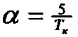

Таким образом, предлагаемый способ поиска неисправной топологической связи блоков сводится к выполнению следующих операций:Thus, the proposed method for finding a faulty topological connection of blocks is reduced to performing the following operations:
1. В качестве динамической системы рассматривают систему, состоящую из произвольно соединенных динамических блоков, с количеством рассматриваемых изменений топологических связей блоков m.1. As a dynamic system, consider a system consisting of randomly connected dynamic blocks, with the number of considered changes in the topological connections of blocks m.
2. Предварительно определяют время контроля TК≥TПП, где TПП - время переходного процесса системы. Время переходного процесса оценивают для номинальных значений параметров динамической системы.2. Pre-determine the control time T To ≥T PP , where T PP - the transition process of the system. The transient time is estimated for the nominal values of the parameters of the dynamic system.
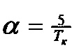
3. Определяют параметр интегрального преобразования сигналов из соотношения 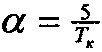
4. Фиксируют число контрольных точек k.4. Fix the number of control points k.
5. Предварительно определяют нормированные векторы 
6. Подают входной сигнал x(t) (единичный ступенчатый, линейно возрастающий, прямоугольный импульсный и т.д.) на вход системы управления с номинальными характеристиками. Принципиальных ограничений на вид входного тестового воздействия предлагаемый способ не предусматривает.6. The input signal x (t) (unit step, linearly increasing, rectangular pulse, etc.) is fed to the input of a control system with nominal characteristics. The proposed method does not provide fundamental restrictions on the type of input test exposure.
7. Регистрируют реакцию системы fjном(t), j=1, …, k на интервале t∈[0, TK] в k контрольных точках и определяют интегральные оценки выходных сигналов Fjном(α), j=1, …, k системы. Для этого в момент подачи тестового сигнала на вход системы управления с номинальными характеристиками одновременно начинают интегрирование сигналов системы управления в каждой из k контрольных точек с весами 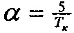
8. Определяют интегральные оценки выходных сигналов модели для каждой из k контрольных точек, полученные в результате использования топологической функции чувствительности, для чего поочередно для каждой из m топологических связей блоков динамической системы соединяют топологической связью две модели: на вход первой модели подают тестовый сигнал x(t), выходом первой модели фиксируют выход блока, к которому подключена рассматриваемая топологическая связь, соединяют выход первой модели со входом второй, входом второй модели фиксируют вход блока, к которому подключена рассматриваемая топологическая связь, снимают выходные сигналы после каждого блока второй модели, полученные выходные сигналы для каждой из k контрольных точек и каждой из m совмещенных моделей с топологической функцией чувствительности Vji(α), j=1, …, k; i=1, …, m регистрируют.8. Determine the integral estimates of the model output signals for each of the k control points obtained by using the topological sensitivity function, for which, for each of the m topological connections of the blocks of the dynamic system, two models are connected by the topological connection: the test signal x ( t), the output of the block to which the considered topological connection is connected is fixed by the output of the first model, the output of the first model is connected to the input of the second, the input of the second model is fixed to the input unit that is connected to the considered topological connection, remove output signals after each block of the second model produced output signals for each of the k control points and each of the m superimposed patterns with the topological feature sensitivity V ji (α), j = 1, ..., k ; i = 1, ..., m are recorded.
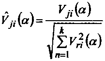
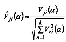
9. Определяют нормированные значения интегральных оценок выходных сигналов модели, полученные в результате использования топологической функции чувствительности соответствующих межблочных связей по формуле 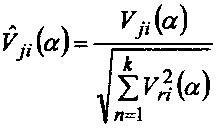
10. Замещают систему с номинальными характеристиками контролируемой. На вход системы подают аналогичный тестовый сигнал x(t).10. Substitute a system with controlled ratings. A similar test signal x (t) is supplied to the system input.
11. Определяют интегральные оценки выходных сигналов контролируемой системы для k контрольных точек Fj(α), j=1, …, k, осуществляя операции, описанные в пунктах 6 и 7 применительно к контролируемой системе.11. Determine the integral estimates of the output signals of the controlled system for k control points F j (α), j = 1, ..., k, performing the operations described in paragraphs 6 and 7 with respect to the controlled system.
12. Определяют отклонения интегральных оценок выходных сигналов контролируемой системы для k контрольных точек от номинальных значений ΔFj(α)=Fj(α)-Fjном(α), j=1, …, k.12. The deviations of the integrated estimates of the output signals of the controlled system for k control points from the nominal values ΔF j (α) = F j (α) -F jnom (α), j = 1, ..., k are determined .
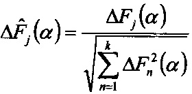
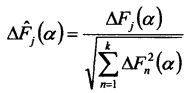
13. Вычисляют нормированные значения отклонений интегральных оценок выходных сигналов контролируемой системы по формуле 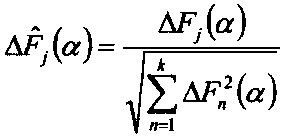
14. Вычисляют диагностические признаки наличия неисправной топологической связи блоков по формуле 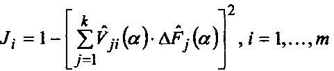
15. По минимуму значения диагностического признака определяют топологический дефект.15. At a minimum, the values of a diagnostic feature determine a topological defect.
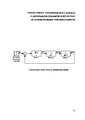
Рассмотрим реализацию предлагаемого способа поиска топологического дефекта для системы, структурная схема которой представлена на чертеже (Структурная схема объекта диагностирования).Consider the implementation of the proposed method for searching for a topological defect for a system whose structural diagram is shown in the drawing (Structural diagram of the diagnostic object).
Передаточные функции блоков:Transfer functions of blocks:

номинальные значения параметров: Т1=5 с; k1=1; k2=1; Т2=1 с; k3=1; Т3=5 с. При поиске топологического дефекта в виде обрыва связи между первым и вторым звеньями (дефект №1), путем подачи ступенчатого тестового входного сигнала единичной амплитуды и интегрального преобразования сигналов для параметра α=0.5 и ТК=10 с получены значения диагностических признаков на основе функции чувствительности при использовании трех контрольных точек, расположенных на выходах блоков: J1=0; J2=0.7536 (обрыв связи между вторым и третьим блоками); J3=0.7892 (обрыв связи между третьим и первым блоками). Минимальное значение признака J1 однозначно указывает на обрыв топологической связи между первым и вторым блоками.nominal values of parameters: T 1 = 5 s; k 1 = 1; k 2 = 1; T 2 = 1 s; k 3 = 1; T 3 = 5 s. When searching for a topological defect in the form of a break in the connection between the first and second links (defect No. 1), by supplying a step test input signal of unit amplitude and integral signal conversion for parameter α = 0.5 and T K = 10 s, the values of diagnostic signs are obtained based on the sensitivity function when using three control points located at the outputs of the blocks: J 1 = 0; J 2 = 0.7536 (disconnection between the second and third blocks); J 3 = 0.7892 (disconnection between the third and first blocks). The minimum value of the sign J 1 unambiguously indicates a break in the topological connection between the first and second blocks.
Для сравнения приведем диагностические признаки наличия топологического дефекта в виде обрыва связи между первым и вторым звеньями (дефект №1) при тех же диагностических параметрах, полученные на основе пробных отклонений состояний топологической связи как в прототипе (Способ поиска неисправностей в непрерывной динамической системе на основе введения пробных отклонений: пат. 2541857 Рос. Федерация: МПК7 G05B 23/02 (2006.01) / Шалобанов С.С. - №2013149468/08; заявл. 06.11.2013; опубл. 16.01.2015, Бюл. №5): J1=0; J2=0.7499 (обрыв связи между вторым и третьим блоками); J3=0.7847 (обрыв связи между третьим и первым блоками).For comparison, we present the diagnostic signs of the presence of a topological defect in the form of a break in the connection between the first and second links (defect No. 1) with the same diagnostic parameters, obtained on the basis of trial deviations of the topological connection states as in the prototype (Troubleshooting method in a continuous dynamic system based on introduction trial deviations: Pat. 2541857 Russian Federation: IPC 7 G05B 23/02 (2006.01) / Shalobanov S.S. - No. 2013149468/08; claimed 06.11.2013; publ. 01.16.2015, Bull. No. 5): J 1 = 0; J 2 = 0.7499 (disconnection between the second and third blocks); J 3 = 0.7847 (disconnection between the third and first blocks).
Моделирование процессов поиска топологических дефектов связей между вторым и третьим, а также третьим и первым блоками для данного объекта диагностирования при тех же диагностических параметрах дает следующие значения диагностических признаков:Modeling of the processes of searching for topological defects of the links between the second and third, as well as the third and first blocks for a given diagnostic object with the same diagnostic parameters gives the following values of diagnostic signs:
При наличии дефекта в виде обрыва топологической связи между вторым и третьим блоками методом функции топологической чувствительности: J1=0.7433; J2=0; J3=0.07391. Для сравнения приведем диагностические признаки наличия топологического дефекта в виде обрыва связи между вторым и третьим звеньями (дефект №2), полученные на основе пробных отклонений состояний топологической связи, как в прототипе: J1=0.7499; J2=0; J3=0.07035.In the presence of a defect in the form of a break in the topological connection between the second and third blocks by the method of the function of topological sensitivity: J 1 = 0.7433; J 2 = 0; J 3 = 0.07391. For comparison, we present diagnostic signs of the presence of a topological defect in the form of a break in the connection between the second and third links (defect No. 2), obtained on the basis of trial deviations of the states of the topological connection, as in the prototype: J 1 = 0.7499; J 2 = 0; J 3 = 0.07035.
При наличии дефекта в виде обрыва топологической связи между третьим и первым блоками методом функции топологической чувствительности: J1=0.7783; J2=0.0695; J3=0. Для сравнения приведем диагностические признаки наличия топологического дефекта в виде обрыва связи между третьим и первым звеньями (дефект №3), полученные на основе пробных отклонений состояний топологической связи, как в прототипе: J1=0.7847; J2=0.07035; J3=0.In the presence of a defect in the form of a break in the topological connection between the third and first blocks by the method of the function of topological sensitivity: J 1 = 0.7783; J 2 = 0.0695; J 3 = 0. For comparison, we present the diagnostic signs of the presence of a topological defect in the form of a break in the connection between the third and first links (defect No. 3), obtained on the basis of trial deviations of the states of topological connection, as in the prototype: J 1 = 0.7847; J 2 = 0.07035; J 3 = 0.
Минимальное значение диагностического признака во всех случаях правильно указывает на наличие топологического дефекта.The minimum value of a diagnostic sign in all cases correctly indicates the presence of a topological defect.
Claims (1)


Priority Applications (1)
| Application Number | Priority Date | Filing Date | Title |
|---|---|---|---|
| RU2016114254A RU2613402C1 (en) | 2016-04-12 | 2016-04-12 | Search method of topological defects in continuous dynamic system based on sensitivity functions |
Applications Claiming Priority (1)
| Application Number | Priority Date | Filing Date | Title |
|---|---|---|---|
| RU2016114254A RU2613402C1 (en) | 2016-04-12 | 2016-04-12 | Search method of topological defects in continuous dynamic system based on sensitivity functions |
Publications (1)
| Publication Number | Publication Date |
|---|---|
| RU2613402C1 true RU2613402C1 (en) | 2017-03-16 |
Family
ID=58458337
Family Applications (1)
| Application Number | Title | Priority Date | Filing Date |
|---|---|---|---|
| RU2016114254A RU2613402C1 (en) | 2016-04-12 | 2016-04-12 | Search method of topological defects in continuous dynamic system based on sensitivity functions |
Country Status (1)
| Country | Link |
|---|---|
| RU (1) | RU2613402C1 (en) |
Cited By (1)
| Publication number | Priority date | Publication date | Assignee | Title |
|---|---|---|---|---|
| RU2661180C1 (en) * | 2017-03-31 | 2018-07-12 | Федеральное государственное бюджетное образовательное учреждение высшего образования "Тихоокеанский государственный университет" | Method of searching for faulty unit in continuous dynamic system based on change of position of input signal |
Citations (5)
| Publication number | Priority date | Publication date | Assignee | Title |
|---|---|---|---|---|
| US4851985A (en) * | 1985-04-15 | 1989-07-25 | Logitek, Inc. | Fault diagnosis system for comparing counts of commanded operating state changes to counts of actual resultant changes |
| EP0969341A2 (en) * | 1998-07-01 | 2000-01-05 | Adaptive Audio, Inc. | Method and apparatus for dynamical system analysis |
| RU2435189C2 (en) * | 2009-06-23 | 2011-11-27 | Государственное образовательное учреждение высшего профессионального образования "Тихоокеанский государственный университет" | Method of searching for faulty unit in dynamic system |
| RU2473106C1 (en) * | 2012-02-28 | 2013-01-20 | Федеральное государственное бюджетное образовательное учреждение высшего профессионального образования "Тихоокеанский государственный университет" | Method of finding faulty units in dynamic system |
| RU2541857C1 (en) * | 2013-11-06 | 2015-02-20 | Федеральное государственное бюджетное образовательное учреждение высшего профессионального образования "Тихоокеанский государственный университет" | Method of finding faults in continuous dynamic system based on input of sample deviations |
-
2016
- 2016-04-12 RU RU2016114254A patent/RU2613402C1/en not_active IP Right Cessation
Patent Citations (5)
| Publication number | Priority date | Publication date | Assignee | Title |
|---|---|---|---|---|
| US4851985A (en) * | 1985-04-15 | 1989-07-25 | Logitek, Inc. | Fault diagnosis system for comparing counts of commanded operating state changes to counts of actual resultant changes |
| EP0969341A2 (en) * | 1998-07-01 | 2000-01-05 | Adaptive Audio, Inc. | Method and apparatus for dynamical system analysis |
| RU2435189C2 (en) * | 2009-06-23 | 2011-11-27 | Государственное образовательное учреждение высшего профессионального образования "Тихоокеанский государственный университет" | Method of searching for faulty unit in dynamic system |
| RU2473106C1 (en) * | 2012-02-28 | 2013-01-20 | Федеральное государственное бюджетное образовательное учреждение высшего профессионального образования "Тихоокеанский государственный университет" | Method of finding faulty units in dynamic system |
| RU2541857C1 (en) * | 2013-11-06 | 2015-02-20 | Федеральное государственное бюджетное образовательное учреждение высшего профессионального образования "Тихоокеанский государственный университет" | Method of finding faults in continuous dynamic system based on input of sample deviations |
Cited By (1)
| Publication number | Priority date | Publication date | Assignee | Title |
|---|---|---|---|---|
| RU2661180C1 (en) * | 2017-03-31 | 2018-07-12 | Федеральное государственное бюджетное образовательное учреждение высшего образования "Тихоокеанский государственный университет" | Method of searching for faulty unit in continuous dynamic system based on change of position of input signal |
Similar Documents
| Publication | Publication Date | Title |
|---|---|---|
| RU2541857C1 (en) | Method of finding faults in continuous dynamic system based on input of sample deviations | |
| RU2429518C1 (en) | Method of fault finding in continuous system dynamic unit | |
| RU2009123999A (en) | METHOD FOR SEARCHING FAULT BLOCK IN DYNAMIC SYSTEM | |
| RU2450309C1 (en) | Method of searching for faults in dynamic unit in continuous system | |
| RU2439647C1 (en) | Method to search for faulty block in continuous dynamic system | |
| CN106650942B (en) | Fault Diagnosis Method Based on Testability Model of Electronic Equipment | |
| RU2528135C1 (en) | Method of searching for faulty unit in continuous dynamic system based on change of position of input signal | |
| RU2439648C1 (en) | Method to search for faulty block in dynamic system | |
| RU2461861C1 (en) | Method of searching for faulty module in continuous dynamic system | |
| RU2444774C1 (en) | Method of searching for faulty module in discrete dynamic system | |
| RU2586859C1 (en) | Method of searching for faulty unit in continuous dynamic system based on change of position of input signal | |
| RU2473105C1 (en) | Method of detecting faults in units in continuous dynamic system | |
| RU2613630C1 (en) | Method for searching faulty unit in continuous dynamic system through introduction of trial deviations | |
| RU2613402C1 (en) | Search method of topological defects in continuous dynamic system based on sensitivity functions | |
| RU2464616C1 (en) | Method of searching for faults in dynamic unit in continuous system | |
| RU2676365C1 (en) | Method of searching faulty unit in continuous dynamic system based on introduction of trial deviations | |
| RU2506623C1 (en) | Method of searching for faulty unit in discrete dynamic system | |
| RU2680928C1 (en) | Method for detecting faulty unit in continuous dynamic system based on sensitivity function | |
| RU2451319C1 (en) | Method of searching for faulty module in dynamic system | |
| RU2580405C1 (en) | Method for troubleshooting dynamic block in a continuous system based on sensitivity functions | |
| RU2453898C1 (en) | Method of detecting faulty units in dynamic system | |
| RU2579543C1 (en) | Method of troubleshooting in discrete dynamical systems based on a change in position input | |
| RU2616512C1 (en) | Method of searching topological defect in continuous dynamic system based on trial deviations introduction | |
| RU2541896C1 (en) | Method of searching for faulty unit in discrete dynamic system based on analysis of signal transmission signs | |
| RU2486568C1 (en) | Method to search for faulty block in continuous dynamic system |
Legal Events
| Date | Code | Title | Description |
|---|---|---|---|
| MM4A | The patent is invalid due to non-payment of fees |
Effective date: 20180413 |