RU2619002C2 - Beverage preparation machine with adjustable nozzle for dispensing - Google Patents
Beverage preparation machine with adjustable nozzle for dispensing Download PDFInfo
- Publication number
- RU2619002C2 RU2619002C2 RU2014133549A RU2014133549A RU2619002C2 RU 2619002 C2 RU2619002 C2 RU 2619002C2 RU 2014133549 A RU2014133549 A RU 2014133549A RU 2014133549 A RU2014133549 A RU 2014133549A RU 2619002 C2 RU2619002 C2 RU 2619002C2
- Authority
- RU
- Russia
- Prior art keywords
- dispensing
- beverage
- nozzle
- movable auxiliary
- machine according
- Prior art date
Links
- 235000013361 beverage Nutrition 0.000 title claims abstract description 79
- 230000007246 mechanism Effects 0.000 claims description 18
- 239000012530 fluid Substances 0.000 claims description 8
- 238000004891 communication Methods 0.000 claims description 4
- 230000002093 peripheral effect Effects 0.000 claims description 3
- 239000007787 solid Substances 0.000 claims 1
- 239000000126 substance Substances 0.000 abstract 1
- 235000013353 coffee beverage Nutrition 0.000 description 19
- XLYOFNOQVPJJNP-UHFFFAOYSA-N water Substances O XLYOFNOQVPJJNP-UHFFFAOYSA-N 0.000 description 8
- 238000013461 design Methods 0.000 description 4
- 230000008901 benefit Effects 0.000 description 3
- 235000015114 espresso Nutrition 0.000 description 3
- 238000001802 infusion Methods 0.000 description 3
- 238000000034 method Methods 0.000 description 3
- 230000001419 dependent effect Effects 0.000 description 2
- 238000005516 engineering process Methods 0.000 description 2
- 239000011521 glass Substances 0.000 description 2
- 239000007788 liquid Substances 0.000 description 2
- 238000012986 modification Methods 0.000 description 2
- 230000004048 modification Effects 0.000 description 2
- 241001122767 Theaceae Species 0.000 description 1
- 230000015572 biosynthetic process Effects 0.000 description 1
- 235000015116 cappuccino Nutrition 0.000 description 1
- 239000002775 capsule Substances 0.000 description 1
- 238000004140 cleaning Methods 0.000 description 1
- 238000010276 construction Methods 0.000 description 1
- 230000005484 gravity Effects 0.000 description 1
- 235000020307 latte macchiato Nutrition 0.000 description 1
- 230000008569 process Effects 0.000 description 1
- 230000001105 regulatory effect Effects 0.000 description 1
Images
Classifications
-
- A—HUMAN NECESSITIES
- A47—FURNITURE; DOMESTIC ARTICLES OR APPLIANCES; COFFEE MILLS; SPICE MILLS; SUCTION CLEANERS IN GENERAL
- A47J—KITCHEN EQUIPMENT; COFFEE MILLS; SPICE MILLS; APPARATUS FOR MAKING BEVERAGES
- A47J31/00—Apparatus for making beverages
- A47J31/44—Parts or details or accessories of beverage-making apparatus
- A47J31/4482—Details allowing to adapt the beverage-making apparatus to the size of the brewing vessel or the beverage container, e.g. with adjustable support for the beverage container or adjustable hot water outlet
-
- A—HUMAN NECESSITIES
- A47—FURNITURE; DOMESTIC ARTICLES OR APPLIANCES; COFFEE MILLS; SPICE MILLS; SUCTION CLEANERS IN GENERAL
- A47J—KITCHEN EQUIPMENT; COFFEE MILLS; SPICE MILLS; APPARATUS FOR MAKING BEVERAGES
- A47J31/00—Apparatus for making beverages
- A47J31/44—Parts or details or accessories of beverage-making apparatus
- A47J31/46—Dispensing spouts, pumps, drain valves or like liquid transporting devices
Landscapes
- Engineering & Computer Science (AREA)
- Food Science & Technology (AREA)
- Apparatus For Making Beverages (AREA)
- Devices For Dispensing Beverages (AREA)
Abstract
Description
ОБЛАСТЬ ТЕХНИКИ, К КОТОРОЙ ОТНОСИТСЯ ИЗОБРЕТЕНИЕFIELD OF THE INVENTION
Настоящее изобретение относится к машинам для приготовления напитков и, в частности, хотя не исключительно, к машинам для приготовления кофе.The present invention relates to machines for making drinks and, in particular, although not exclusively, to machines for making coffee.
ПРЕДПОСЫЛКИ ИЗОБРЕТЕНИЯBACKGROUND OF THE INVENTION
Машины для приготовления кофе становятся все больше и больше популярными и широко используемыми бытовыми устройствами.Coffee making machines are becoming more and more popular and widely used household appliances.
Эти машины широко используются для приготовления различных типов напитков на основе кофе, таких как кофе эспрессо, свежесваренный кофе (американский кофе), кофе «капучино», «латте макиато» и так далее. В зависимости от типа напитка и желаний пользователя напиток собирают в меньшую или большую емкость, такую как чашка для эспрессо, большую чашку для чая или кофейную чашку или им подобное. Для обеспечения использования емкостей, значительно отличающихся по высоте, были созданы машины, которые содержат средство для регулирования расстояния между опорной поверхностью для чашки и патрубком для дозирования напитка. Патент США 7654192 раскрывает кофемашину, имеющую вертикально регулируемый и закрываемый сливной узел, содержащую довольно сложный механизм для регулировки расстояния между патрубком для дозирования напитка и опорной поверхностью для чашки.These machines are widely used for preparing various types of coffee-based drinks, such as espresso, freshly brewed coffee (American coffee), cappuccino, latte macchiato and so on. Depending on the type of beverage and the wishes of the user, the beverage is collected in a smaller or larger container, such as an espresso cup, a large tea cup, or a coffee cup or the like. To ensure the use of containers, significantly different in height, machines were created that contain means for regulating the distance between the supporting surface for the cup and the nozzle for dispensing the drink. US 7654192 discloses a coffee machine having a vertically adjustable and lockable drain assembly comprising a rather complex mechanism for adjusting the distance between the beverage dispensing nozzle and the cup support surface.
EP-A-1639926 раскрывает машину для приготовления кофе, содержащую патрубок для дозирования напитка, расположенный в неподвижном положении, и опорную поверхность для чашки, находящуюся внизу, которая может регулироваться таким образом, что расстояние между опорной поверхностью и патрубком для дозирования напитка является подогнанным к размеру чашки или другой емкости, расположенной под патрубком для дозирования напитка. Кроме того, в этом случае регулировочный механизм является довольно сложным и дорогим.EP-A-1639926 discloses a coffee brewing machine comprising a nozzle for dispensing a beverage located in a stationary position and a support surface for a cup located below, which can be adjusted so that the distance between the support surface and the nozzle for dispensing a beverage is adapted to the size of the cup or other container located under the nozzle for dispensing the drink. In addition, in this case, the adjusting mechanism is quite complex and expensive.
Кроме того, средство для регулировки расстояния между патрубком для дозирования напитка и опорной поверхностью для чашки этих известных машин является громоздким и требует довольно большого кожуха.In addition, the means for adjusting the distance between the nozzle for dispensing the beverage and the supporting surface for the cup of these known machines is cumbersome and requires a rather large casing.
КРАТКОЕ ОПИСАНИЕ ИЗОБРЕТЕНИЯSUMMARY OF THE INVENTION
В соответствии с одним аспектом настоящее изобретение описывает машину для приготовления кофе или, в более общем смысле, машину для приготовления напитка, содержащую простое, недорогое средство для регулировки расстояния между опорной поверхностью, на которой устанавливают чашку, и патрубком для дозирования напитка. Задачей предпочтительных вариантов осуществления настоящего изобретения является создание машины для приготовления напитка, имеющей компактные размеры и обеспечивающей использование больших или меньших емкостей или чашек для сбора напитка.In accordance with one aspect, the present invention describes a coffee brewing machine or, more generally, a beverage brewing machine comprising a simple, inexpensive means for adjusting the distance between a supporting surface on which a cup is mounted and a nozzle for dispensing a beverage. An object of the preferred embodiments of the present invention is to provide a machine for preparing a beverage having compact dimensions and allowing the use of larger or smaller containers or cups for collecting a beverage.
Настоящее изобретение определено независимым пунктом формулы изобретения. Зависимые пункты формулы изобретения определяют другие преимущественные варианты осуществления и признаки настоящего изобретения.The present invention is defined by an independent claim. The dependent claims define other advantageous embodiments and features of the present invention.
В соответствии с настоящим изобретением описана машина для приготовления напитка, содержащая кожух, опорную поверхность, на которой может устанавливаться емкость для сбора напитка, патрубок для дозирования напитка, расположенный над упомянутой опорной поверхностью. Кроме того, обеспечена подвижная вспомогательная поверхность, соединенная с опорной поверхностью, причем упомянутая подвижная вспомогательная поверхность перемещается между рабочим положением, в котором упомянутая подвижная вспомогательная поверхность приблизительно параллельна упомянутой опорной поверхности, и исходным положением, в котором упомянутая подвижная вспомогательная поверхность удалена с упомянутой опорной поверхности. Патрубок для дозирования перемещается между первым положением для дозирования напитка, полученного при помощи заварочного узла или ему подобного, в емкость, расположенную на опорной поверхности, и вторым положением для дозирования упомянутого напитка в емкость, расположенную на упомянутой подвижной вспомогательной поверхности.In accordance with the present invention, a machine for preparing a beverage is described, comprising a casing, a supporting surface on which a container for collecting a beverage can be mounted, a nozzle for dispensing a beverage located above said supporting surface. Furthermore, a movable auxiliary surface connected to the abutment surface is provided, said movable auxiliary surface being moved between a working position in which said movable auxiliary surface is approximately parallel to said abutment surface and a starting position in which said movable auxiliary surface is removed from said abutment surface . The dispensing nozzle is moved between the first position for dispensing the beverage obtained by the brewing unit or the like in a container located on the supporting surface and the second position for dispensing the beverage in a container located on the movable auxiliary surface.
Конструкция является такой, что большие емкости могут использоваться посредством перемещения патрубка для дозирования и подвижной вспомогательной поверхности в положение на наружной стороне основания машины. Следовательно, машина может быть выполнена с очень маленькими размерами и, в частности, небольшим основанием. Таким образом, машину легко перемещать и можно устанавливать в помещениях, где имеется немного места, например на небольшой кухне. Тем не менее, машина обеспечивает возможность ее приспособления для дозирования напитка в большую чашку или емкость путем простого временного наклона патрубка для дозирования и подвижной вспомогательной поверхности в выступающее наружу положение. Когда не требуется, подвижная вспомогательная поверхность и патрубок для дозирования могут быть наклонены обратно в соответствующие исходные положения, в которых они не выступают на наружную сторону основания машины.The design is such that large containers can be used by moving the metering nozzle and the movable auxiliary surface to a position on the outside of the machine base. Therefore, the machine can be made with very small dimensions and, in particular, a small base. Thus, the machine is easy to move and can be installed in rooms where there is little space, such as a small kitchen. However, the machine allows it to be adapted to dispense the beverage into a large cup or container by simply temporarily tilting the dispensing nozzle and the movable auxiliary surface to the outwardly protruding position. When not required, the movable auxiliary surface and the metering nozzle can be tilted back to their respective starting positions, in which they do not protrude on the outside of the machine base.
В некоторых вариантах осуществления патрубок для дозирования напитка обеспечивает наклонное движение для перемещения из упомянутого первого положения в упомянутое второе положение и наоборот. Подобным образом, в примерах осуществления и предпочтительных вариантах осуществления подвижная вспомогательная поверхность поворачивается вокруг оси, по существу параллельной опорной поверхности, для перемещения из исходного положения в рабочее положение и наоборот.In some embodiments, the beverage dispensing nozzle provides oblique movement to move from said first position to said second position and vice versa. Similarly, in the embodiments and preferred embodiments, the movable support surface is rotated about an axis substantially parallel to the abutment surface to move from a starting position to a working position and vice versa.
В некоторых вариантах осуществления при нахождении в исходном положении подвижная вспомогательная поверхность расположена рядом с упомянутым кожухом и, по существу, перпендикулярна к опорной поверхности. В рабочем положении подвижная вспомогательная поверхность выступает относительно упомянутого кожуха за опорную поверхность, и в упомянутом втором положении патрубок для дозирования напитка выступает из упомянутого кожуха.In some embodiments, when in the initial position, the movable auxiliary surface is located adjacent to said casing and is substantially perpendicular to the abutment surface. In the operating position, the movable auxiliary surface protrudes relative to the said casing beyond the supporting surface, and in the said second position, the nozzle for dispensing the beverage projects from the said casing.
В соответствии с некоторыми вариантами осуществления в первом положении патрубок для дозирования напитка находится в сообщении по текучей среде со сливной трубкой, неподвижно расположенной в упомянутом кожухе и над упомянутой опорной поверхностью, так что напиток дозируется из патрубка для дозирования напитка в сливную трубку и из сливной трубки в емкость, установленную на опорной поверхности. Во втором положении патрубок для дозирования напитка расположен для дозирования напитка из патрубка для дозирования напитка в емкость, установленную на подвижной вспомогательной поверхности, расположенной в рабочем положении.According to some embodiments, in a first position, the beverage dispensing nozzle is in fluid communication with a drain pipe fixedly located in said casing and above said abutment surface, so that the beverage is dispensed from the beverage dispensing nozzle into the drain pipe and from the drain pipe into a container mounted on a supporting surface. In the second position, the nozzle for dispensing the beverage is located to dispense the beverage from the nozzle for dispensing the beverage into a container mounted on a movable auxiliary surface located in the working position.
В некоторых примерах осуществления кожух имеет передний участок, выступающий от основного корпуса и над опорной поверхностью, и патрубок для дозирования напитка установлен на упомянутом переднем участке, например в углублении или выемке, образованной на переднем участке. В некоторых вариантах осуществления выпускная трубка установлена на переднем участке кожуха, обращенном к опорной поверхности, расположенной внизу, и подвижная вспомогательная поверхность предпочтительно шарнирно соединена с основным корпусом кожуха под упомянутым передним участком.In some embodiments, the casing has a front portion protruding from the main body and above the abutment surface, and a nozzle for dispensing the beverage is mounted on said front portion, for example in a recess or recess formed in the front portion. In some embodiments, the exhaust pipe is mounted on the front portion of the casing facing the abutment surface located below, and the movable auxiliary surface is pivotally connected to the main body of the casing under said front portion.
При наличии углубления для вмещения патрубка для дозирования, когда патрубок для дозирования находится в первом положении, упомянутое углубление может содержать закрывающую заслонку. В предпочтительных вариантах осуществления патрубок для дозирования напитка может быть соединен с заслонкой так, что патрубок для дозирования напитка может перемещаться из первого положения во второе положение и наоборот посредством открытия и закрытия упомянутой заслонки.If there is a recess for receiving the dispensing nozzle, when the dispensing nozzle is in the first position, said recess may comprise a closing flap. In preferred embodiments, the nozzle for dispensing the beverage may be connected to the flapper so that the nozzle for dispensing the beverage can be moved from the first position to the second position and vice versa by opening and closing said flapper.
Для упрощения регулировки машины для приготовления кофе в некоторых вариантах осуществления механическое соединение обеспечено между патрубком для дозирования и подвижной вспомогательной поверхностью. Механическое соединение может быть выполнено таким образом, что действуя только на патрубок для дозирования, перемещаются как патрубок для дозирования, так и подвижная вспомогательная поверхность или наоборот. В некоторых вариантах осуществления может быть обеспечен рычажный механизм, непосредственно или косвенно соединенный с патрубком для дозирования и действующий совместно с подвижной вспомогательной поверхностью. Рычажный механизм может быть предназначен и установлен для принудительного поворота подвижной вспомогательной поверхности из исходного положения в рабочее положение при перемещении патрубка для дозирования из первого положения во второе положение. Кроме того, рычажный механизм может быть предназначен и расположен таким образом, что упомянутый рычажный механизм заставляет патрубок для дозирования напитка наклоняться из второго положения в первое положение при перемещении подвижной вспомогательной поверхности из рабочего положения в исходное положение. В других вариантах осуществления конструкция рычажного механизма может быть такой, что, когда пользователь наклоняет подвижную вспомогательную поверхность из исходного положения в рабочее положение, патрубок для дозирования также перемещается из первого положения во второе положение, и когда пользователь перемещает патрубок для дозирования из второго положения в первое положение, рычажный механизм вызывает обратное перемещение подвижной вспомогательной поверхности из рабочего положения в исходное положение. Эти конструкции делают возможным перемещение из одного рабочего положения в другое простым способом, например, используя только одну руку для воздействия на патрубок для дозирования и, в качестве альтернативы, на подвижную вспомогательную поверхность, делая регулировку машины для приготовления напитка более легкой и более удобной в использовании.To simplify the adjustment of the coffee brewing machine, in some embodiments, a mechanical connection is provided between the dispensing nozzle and the movable auxiliary surface. The mechanical connection can be made in such a way that acting only on the metering nozzle, both the metering nozzle and the movable auxiliary surface or vice versa are moved. In some embodiments, a linkage mechanism may be provided that is directly or indirectly connected to the metering nozzle and acts in conjunction with a movable auxiliary surface. The lever mechanism can be designed and installed for forced rotation of the movable auxiliary surface from its original position to the working position when moving the pipe for dispensing from the first position to the second position. In addition, the lever mechanism can be designed and positioned in such a way that said lever mechanism causes the nozzle for dispensing the beverage to tilt from the second position to the first position when moving the movable auxiliary surface from the working position to its original position. In other embodiments, the design of the linkage mechanism may be such that when the user tilts the movable supporting surface from the starting position to the working position, the dispensing nozzle also moves from the first position to the second position, and when the user moves the dispensing nozzle from the second position to the first position, the lever mechanism causes the reverse movement of the movable auxiliary surface from the working position to its original position. These designs make it possible to move from one operating position to another in a simple way, for example, using only one hand to act on the nozzle for dispensing and, alternatively, on the movable auxiliary surface, making the adjustment of the machine for making the beverage easier and more convenient to use .
Признаки и варианты осуществления раскрыты в данном документе ниже и дополнительно изложены в прилагаемой формуле изобретения, которая составляет неотъемлемую часть настоящего описания. Вышеприведенное краткое описание излагает признаки различных вариантов осуществления настоящего изобретения для того, чтобы нижеследующее подробное описание можно было лучше понять и чтобы усовершенствования существующей техники могли быть лучше понятны. Имеются другие признаки настоящего изобретения, которые будут описаны ниже и которые будут изложены в прилагаемой формуле изобретения. В связи с этим, до подробного объяснения нескольких вариантов осуществления настоящего изобретения, понятно, что различные варианты осуществления не ограничены в их применении особенностями конструкции и расположениями элементов, изложенными в нижеследующем описании или проиллюстрированными на чертежах. Настоящее изобретение допускает другие варианты осуществления и применения на практике и осуществляется различными способами. Кроме того, следует понимать, что фразеология и терминология, используемые в данном документе, предназначены для описания и не должны рассматриваться как ограничивающие.Signs and embodiments are disclosed herein below and are further set forth in the accompanying claims, which forms an integral part of the present description. The above brief description sets forth the features of various embodiments of the present invention so that the following detailed description can be better understood and that improvements to existing technology can be better understood. There are other features of the present invention, which will be described below and which will be set forth in the attached claims. In this regard, before a detailed explanation of several embodiments of the present invention, it is understood that various embodiments are not limited in their application to the structural features and arrangement of elements set forth in the following description or illustrated in the drawings. The present invention allows for other embodiments and practical applications and is carried out in various ways. In addition, it should be understood that the phraseology and terminology used in this document are intended to describe and should not be construed as limiting.
По существу, специалисты в данной области техники должны понимать, что идея, на которой основано раскрытие, может быть легко использована в качестве основы для разработки других конструкций, способов и/или систем для осуществления нескольких целей настоящего изобретения. Важно, таким образом, чтобы формула изобретения рассматривалась как включающая такие эквивалентные конструкции в такой степени, чтобы они не отходили от сущности и объема настоящего изобретения.As such, those skilled in the art should understand that the idea on which the disclosure is based can easily be used as a basis for developing other designs, methods, and / or systems to accomplish several objectives of the present invention. It is important, therefore, that the claims be considered to include such equivalent constructions to such an extent that they do not depart from the essence and scope of the present invention.
КРАТКОЕ ОПИСАНИЕ ЧЕРТЕЖЕЙBRIEF DESCRIPTION OF THE DRAWINGS
Более полное понимание раскрытых вариантов осуществления настоящего изобретения и многие соответствующие их преимущества будут легко получены, так как то же самое становится лучше понятно со ссылкой на нижеследующее подробное описание при рассмотрении вместе с сопроводительными чертежами, на которыхA more complete understanding of the disclosed embodiments of the present invention and many of their corresponding advantages will be easily obtained, since the same becomes better understood with reference to the following detailed description when considered in conjunction with the accompanying drawings, in which
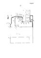
фиг. 1 - вид сбоку и в частичном разрезе машины для приготовления напитка в соответствии с настоящим изобретением с патрубком для дозирования, расположенным в первом положении;FIG. 1 is a side view and in partial section of a machine for preparing a beverage in accordance with the present invention with a dispensing nozzle located in a first position;
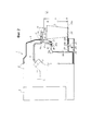
фиг. 2 изображает машину на фиг. 1 с патрубком для дозирования, расположенным во втором положении;FIG. 2 shows the machine of FIG. 1 with a nozzle for dispensing located in the second position;
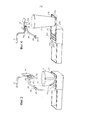
фиг. 3 и 4 - перспективный вид патрубка для дозирования и подвижной вспомогательной поверхности в двух рабочих положениях, соответствующих положениям на фиг. 1 и 2 соответственно;FIG. 3 and 4 are a perspective view of a dispensing nozzle and a movable auxiliary surface in two operating positions corresponding to those in FIG. 1 and 2, respectively;
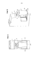
фиг. 5 и 6 - вид спереди и перспективный вид переднего участка машины в положении на фиг. 2.FIG. 5 and 6 are a front view and a perspective view of the front portion of the machine in the position of FIG. 2.
ПОДРОБНОЕ ОПИСАНИЕ ВАРИАНТА ОСУЩЕСТВЛЕНИЯDETAILED DESCRIPTION OF EMBODIMENT
Нижеследующее подробное описание примеров осуществления ссылается на сопроводительные чертежи. Одни и те же ссылочные позиции на разных чертежах обозначают одни и те же или подобные элементы. Кроме того, чертежи не обязательно выполнены в масштабе. Кроме того, нижеследующее подробное описание не ограничивает настоящее изобретение. Между тем, объем настоящего изобретения определен прилагаемой формулой изобретения.The following detailed description of exemplary embodiments refers to the accompanying drawings. The same reference numbers in different drawings indicate the same or similar elements. In addition, the drawings are not necessarily drawn to scale. In addition, the following detailed description does not limit the present invention. Meanwhile, the scope of the present invention is defined by the attached claims.
Ссылка в описании на «один вариант осуществления» или «вариант осуществления» или «некоторые варианты осуществления» означает, что конкретный признак, конструкция или характеристика, описанные вместе с вариантом осуществления, включены в, по меньшей мере, один вариант осуществления раскрытого предмета. Таким образом, появление фразы «в одном варианте осуществления» или «в варианте осуществления» или «в некоторых вариантах осуществления» в различных местах в описании не обязательно относится к одному и тому же варианту осуществления (одним и тем же вариантам осуществления). Кроме того, конкретные признаки, конструкции или характеристики могут быть объединены любым подходящим способом в одном или более вариантах осуществления.A reference in the description to “one embodiment” or “an embodiment” or “some embodiments” means that a particular feature, structure, or characteristic described with an embodiment is included in at least one embodiment of the disclosed subject. Thus, the appearance of the phrase “in one embodiment” or “in an embodiment” or “in some embodiments” at various places in the description does not necessarily refer to the same embodiment (the same embodiments). In addition, specific features, structures, or characteristics may be combined in any suitable manner in one or more embodiments.
Ниже будет сделана ссылка на кофемашину. Однако следует понимать, что настоящее изобретение может быть осуществлено также в других машинах для приготовления напитка, когда возникает необходимость в использовании чашек или емкостей различных размеров с последующей необходимостью регулирования расстояния между опорной поверхностью для емкости для сбора напитка и патрубком для дозирования напитка.A link will be made below to the coffee machine. However, it should be understood that the present invention can also be implemented in other machines for preparing a beverage when it becomes necessary to use cups or containers of various sizes, followed by the need to control the distance between the supporting surface for the container for collecting the beverage and the nozzle for dispensing the beverage.
На чертежах кофемашина обозначена, в целом, ссылочной позицией 1. Кофемашина 1 включает в себя кожух 3 с передним выступающим участком 5. Устройство патрубка для дозирования напитка размещено на переднем выступающем участке 5 кофемашины 3, как будет раскрыто в данном документе ниже. В примере осуществления, описанном в данном документе, заварочный узел также расположен в кожухе 3. Другие элементы, части и средства дополнительно расположены в кожухе 3 или вокруг него, такие как емкость для воды, водяной насос, водонагреватель, центральный блок управления, датчики температуры и уровня, механизмы манипулирования с капсулами с кофе и т.д. Эти элементы, части и средства хорошо известны специалистам в данной области техники и не будут очень подробно описаны в данном документе.In the drawings, the coffee machine is generally designated by the reference numeral 1. The coffee machine 1 includes a
В задней части кожуха 3 может быть установлена емкость 9 для воды, из которой вода всасывается насосом (не показан), который подает воду при необходимом давлении в водонагреватель для получения необходимой горячей и под давлением воды для заварки для подачи в заварочный узел 7.In the back of the
Заварочный узел 7 находится в сообщении по текучей среде через трубку 11 с патрубком 13 для дозирования. В некоторых вариантах осуществления трубка 11 является, по меньшей мере, частично гибкой, так что патрубок 13 для дозирования напитка может занимать два разных положения, изображенных на фиг. 1 и 2 и на фиг. 3 и 4 соответственно.The brewing unit 7 is in fluid communication through the
Патрубок 13 для дозирования соединен с заслонкой или крышкой 15. Заслонка 15 соединена с возможностью поворота с передним участком 5 кожуха 3 и может поворачиваться вокруг, по существу, горизонтальной оси 17.The dispensing
В закрытом положении (фиг. 1 и 3) заслонка 15 закрывает гнездо 19, расположенное на переднем участке 5 кожуха 3. В упомянутом закрытом положении патрубок 13 для дозирования напитка полностью вмещен в гнездо 19. Дистальный конец 13A патрубка 13 для дозирования напитка механически соединен со сливной трубкой 21 для установки соединения по текучей среде между патрубком 13 для дозирования и сливной трубкой 21. В варианте осуществления, изображенном на чертежах, сливная трубка 21 по существу ориентирована вертикально, и ее дистальный конец 21A обращен к опорной поверхности 23, на которой может быть установлена емкость для сбора напитка, такая как чашка C, для сбора напитка, приготовленного машиной 1.In the closed position (Figs. 1 and 3), the
Опорная поверхность 23 может быть выполнена в виде решетки, содержащей прорези, каналы или отверстия 23A, через которые жидкость может стекать в сборный поддон, расположенный под опорной поверхностью 23 (не показан). Опорная поверхность 23 и поддон для сбора капель могут быть съемными для удобства очистки.The supporting
Расстояние между опорной поверхностью 23 и нижним концом сливной трубки 21 является таким, что чашка C может быть расположена на опорной поверхности 23 для сбора кофе, дозируемого через сливную трубку 21. Для того чтобы чашка C была расположена в этом положении, высота (h) чашки должна быть меньше расстояния (d) между дистальным концом 21A сливной трубки 21 и опорной поверхностью 23.The distance between the
Если большая (более высокая) емкость для сбора напитка используется вместо чашки C, например стакан, положение патрубка 13 для дозирования будет изменено, подвижная вспомогательная поверхность будет расположена по существу в горизонтальном положении для расположения на ней большей емкости, как будет раскрыто ниже.If a larger (higher) beverage collecting container is used instead of a cup C, such as a glass, the position of the dispensing
В положении, изображенном на фиг. 1 и 3, кофе или любой другой напиток, приготовленный машиной 1, проходит через трубку 9, патрубок 13 для дозирования напитка и сливную трубку 21 для окончательного сбора в емкости C.In the position shown in FIG. 1 and 3, coffee or any other beverage prepared by machine 1 passes through a
На фиг. 2 и 4 положение патрубка 13 для дозирования напитка было изменено для дозирования напитка в более высокую емкость C1, например большую чашку или стакан. Для этой цели патрубок 13 для дозирования напитка поворачивают вокруг оси 17 поворота посредством поворота заслонки 15, с которой соединен патрубок 13 для дозирования напитка. В этом положении патрубок 13 для дозирования напитка выступает вперед на наружную сторону гнезда 19, расположенного на выступающем переднем участке 5 кожуха 3 машины 1. Следовательно, дистальный конец 13A патрубка 13 для дозирования напитка отсоединен от сливной трубки 21 и ориентирован вниз к емкости C1.In FIG. 2 and 4, the position of the
Наклонное движение патрубка 13 для дозирования напитка является возможным за счет гибкости, по меньшей мере, одного участка трубки 11, который будет сгибаться в местоположении 11A, как показано на фиг. 2 и 4.The oblique movement of the
Поскольку дистальный конец 13A патрубка 13 для дозирования напитка в этом положении выступает на наружную сторону основания машины, в варианте осуществления, раскрытом в данном документе, обеспечена подвижная вспомогательная поверхность 25, которая обычно находится в основании машины, т.е. не выступает на наружную сторону основания машины, и которая выступает из него только по необходимости. Подвижная вспомогательная поверхность 25 может поддерживаться парой поворотных рычагов 27, соединенных шарнирно на оси 29 поворота с кожухом 3 или его выступом 3A. В варианте осуществления, изображенном на чертежах, ось поворота подвижной вспомогательной поверхности 25 и соответствующих поворотных рычагов 27 находится под опорной поверхностью 23, и рычаги 27 перемещаются в соответствующих прорезях 23S, образованных на поверхности 23 на ее обеих боковых сторонах. Расстояние D между патрубком 13 для дозирования и подвижной вспомогательной поверхностью 25 больше высоты H емкости C1.Since the
В некоторых вариантах осуществления подвижная вспомогательная поверхность 25, по меньшей мере, частично окружена периферийным выступом 25B, так что любая жидкость, капающая на подвижную вспомогательную поверхность 25, будет предотвращена от просачивания на опорную поверхность машины, например стол или полку, а скорее будет собираться в поддон, расположенный под опорной поверхностью 23 с отверстиями. Это может быть получено, например, за счет образования канала на вспомогательной поверхности 25 в области, перекрывающей опорную поверхность 23 с отверстиями. В варианте осуществления, изображенном на чертежах, сбор жидкости становится возможным за счет периферийного выступа 25, прерванного вдоль кромки вспомогательной поверхности 25, который ориентирован к машине 1 и перекрывает опорную поверхность 23 с отверстиями.In some embodiments, the movable
В положении, изображенном на фиг. 3 и 4, большая емкость C1 может, таким образом, поддерживаться подвижной вспомогательной поверхностью при приведении последней в по существу горизонтальное положение, изображенное на вышеупомянутых чертежах, так что подвижная вспомогательная поверхность 25 и емкость C1 расположены под выступающим наружу патрубком 13 для дозирования напитка, причем дозирующие отверстия на дистальном конце 13A патрубка 13 для дозирования напитка находятся над емкостью C1.In the position shown in FIG. 3 and 4, a large container C1 can thus be supported by a movable auxiliary surface when the latter is brought to a substantially horizontal position as shown in the above drawings, so that the movable
Как можно понять, глядя на фиг. 2 и 4, в этом положении вспомогательная подвижная поверхность 25 по существу параллельна опорной поверхности 23 и выступает за наружную сторону последней и перед кофемашиной 1.As can be understood by looking at FIG. 2 and 4, in this position, the auxiliary
Для перемещения патрубка 13 для дозирования и подвижной вспомогательной поверхности 25 из положения на фиг. 1 и 3 в положение на фиг. 2, 4, 5 и 6 в некоторых вариантах осуществления предусмотрен рычажный механизм между заслонкой 15 и подвижной вспомогательной поверхностью 25, так что заслонка 15 и подвижная вспомогательная поверхность 25 могут перемещаться из одного положения в другое и наоборот посредством воздействия только на одну из них, делая регулировку машины более простой.To move the
В варианте осуществления, изображенном на чертежах, вышеупомянутый рычажный механизм содержит два кронштейна 31, зацепленные с возможностью поворота с заслонкой 15. Ссылочная позиция 33 обозначает горизонтально ориентированную ось поворота, вокруг которой кронштейны 31 соединены шарнирно с заслонкой 15, причем ось 33 параллельна оси 17. Противоположные концы кронштейнов 31 зацеплены с возможностью поворота на оси 34 поворота со скользящим зацепляющим элементом 35.In the embodiment depicted in the drawings, the aforementioned linkage mechanism comprises two
При повороте заслонки 15 ее поворотное движение передается кронштейнами 31 для вызывания скользящего движения в соответствии с двойной стрелкой 35, как можно понять, глядя на фиг. 1 и 2.When the
Работа машины изложена ниже. Если используется небольшая емкость, например чашка C для кофе «эспрессо», машина 1 установлена в положении, изображенном на фиг. 1 и 3. Передняя заслонка 15 закрыта. Патрубок 13 для дозирования вмещен в гнездо 19 и находится в соединении по текучей среде через его дистальный конец 13A с вертикально ориентированной сливной трубкой 21. Кофе, приготовленный варочным узлом 7, проходит через трубку 11, патрубок 13 для дозирования и сливную трубку 21 непосредственно в чашку C, которая установлена на опорной поверхности 23, расположенной под передним участком 5 машины 1.The operation of the machine is described below. If a small container is used, such as an espresso cup C, machine 1 is set to the position shown in FIG. 1 and 3.
В этом положении подвижная вспомогательная поверхность расположена в исходном положении, причем упомянутая подвижная вспомогательная поверхность 25 является по существу вертикальной и упирается торцом в переднюю панель 3B кожуха 3 машины 1 за областью, где должна быть установлена емкость или чашка C.In this position, the movable auxiliary surface is located in the initial position, said movable
Если пользователь хочет использовать большую емкость C1, все, что ему нужно сделать, так это повернуть заслонку 15 вокруг оси 17 поворота для перемещения ее из положения на фиг. 1 и 3 в положение на фиг. 2, 4, 5 и 6. Это поворотное движение, которое может быть осуществлено, например, за счет обеспечения ручки на заслонке 15 (не показана), вызывает последующее перемещение. Патрубок 13 для дозирования напитка перемещается вместе с заслонкой 15 из по существу вертикального положения (фиг. 1 и 3) в по существу горизонтальное положение, причем дистальный конец 13A обращен вниз. Кронштейны 31, соединенные шарнирно с заслонкой 15, осуществляют совместное вращение и поступательное движение, которое передается зацепляющему элементу 35, заставляя последний перемещаться из отведенного назад положения (фиг. 1) в извлеченное положение (фиг. 2). Это перемещение заставляет подвижную вспомогательную поверхность 25 наклоняться вниз из вертикального положения в горизонтальное положение. Это становится возможным, поскольку в положении, изображенном на фиг. 1 и 3, верхняя кромка 25A подвижной вспомогательной поверхности 25 расположена спереди зацепляющего элемента 35. Следовательно, скользящее движение вперед зацепляющего элемента 35 толкает подвижную вспомогательную поверхность 25 наружу из исходного положения до тех пор, пока последняя, в конечном счете, не наклонится в горизонтальное положение под действием силы тяжести.If the user wants to use a large container C1, all he needs to do is turn the
Простое перемещение заслонки 15 является, таким образом, достаточным для приведения как патрубка 13 для дозирования напитка, так и подвижной вспомогательной поверхности 25 в рабочее положение на фиг. 2, 4-6.A simple movement of the
Когда пользователю нужно переместить машину обратно из положения на фиг. 2, 4-6 в положение на фиг. 1 и 3, все, что ему нужно сделать, так это повернуть подвижную вспомогательную поверхность 25 вокруг оси 29 поворота обратно в по существу вертикальное исходное положение. Во время этого перемещения верхняя кромка 25A подвижной вспомогательной поверхности 25, т.е. кромка напротив оси 29 поворота, зацепляется с зацепляющим элементом 35 и отводит его обратно в исходное положение, изображенное на фиг. 1 и 3. Это скользящее движение в соответствии с двойной стрелкой f35 передается при помощи кронштейнов 31 заслонки 15, которая, таким образом, наклоняется вокруг оси 17 поворота обратно в закрытое положение, изображенное на фиг. 1 и 3. Патрубок 13 для дозирования напитка приводится обратно в положение с дистальным концом 13A в сообщение по текучей среде с проксимальным концом дозирующей трубки 21.When the user needs to move the machine back from the position in FIG. 2, 4-6 to the position in FIG. 1 and 3, all he needs to do is rotate the
Хотя раскрытые варианты осуществления предмета, описанные в данном документе, были показаны на чертежах и полностью описаны обстоятельно и подробно вместе с несколькими примерами осуществления, специалисты в данной области техники должны понимать, что возможны многие модификации, изменения и пропуски без существенного отхода от новых идей, принципов и понятий, изложенных в данном документе, и преимуществ предмета, изложенных в прилагаемой формуле изобретения. Следовательно, надлежащий объем усовершенствований должен определяться только на основании самого широкого толкования формулы изобретения для осуществления всех таких модификаций, изменений и пропусков. Кроме того, порядок или последовательность этапов любого процесса или способа могут быть изменены или повторно установлены в соответствии с альтернативными вариантами осуществления. Слово «содержащий» не исключает присутствие элементов или этапов, отличных от элементов и этапов, перечисленных в пункте формулы изобретения. Единственное число соответствующего элемента не исключает присутствие множественного числа таких элементов. В пункте формулы изобретения устройства, перечисляющем несколько средств, некоторые из этих средств могут быть осуществлены в одном и том же изделии устройства. Сам по себе тот факт, что конкретные меры перечислены во взаимно-разных зависимых пунктах формулы изобретения, не означает, что сочетание этих мер не может быть использовано для получения преимущества.Although the disclosed embodiments of the subject matter described herein have been shown in the drawings and are fully described in detail and in detail together with several implementation examples, those skilled in the art should understand that many modifications, changes and omissions are possible without substantially departing from new ideas. principles and concepts set forth in this document, and the advantages of the subject matter set forth in the attached claims. Therefore, the proper scope of improvements should be determined only on the basis of the broadest interpretation of the claims for all such modifications, changes and omissions. In addition, the order or sequence of steps of any process or method can be changed or reinstalled in accordance with alternative embodiments. The word “comprising” does not exclude the presence of elements or steps other than the elements and steps listed in a claim. The singular of the corresponding element does not exclude the presence of the plural of such elements. In the claims of a device listing several means, some of these means may be implemented in the same device product. The mere fact that specific measures are listed in mutually different dependent claims does not mean that a combination of these measures cannot be used to take advantage.
Claims (16)
Applications Claiming Priority (3)
| Application Number | Priority Date | Filing Date | Title |
|---|---|---|---|
| US201261587184P | 2012-01-17 | 2012-01-17 | |
| US61/587,184 | 2012-01-17 | ||
| PCT/IB2013/050388 WO2013108185A1 (en) | 2012-01-17 | 2013-01-16 | Adjustable dispensing nozzle |
Publications (2)
| Publication Number | Publication Date |
|---|---|
| RU2014133549A RU2014133549A (en) | 2016-03-10 |
| RU2619002C2 true RU2619002C2 (en) | 2017-05-11 |
Family
ID=47749908
Family Applications (1)
| Application Number | Title | Priority Date | Filing Date |
|---|---|---|---|
| RU2014133549A RU2619002C2 (en) | 2012-01-17 | 2013-01-16 | Beverage preparation machine with adjustable nozzle for dispensing |
Country Status (9)
| Country | Link |
|---|---|
| US (1) | US9648981B2 (en) |
| EP (1) | EP2804511B1 (en) |
| JP (1) | JP6130859B2 (en) |
| CN (1) | CN104053386B (en) |
| BR (1) | BR112014017299A8 (en) |
| ES (1) | ES2672696T3 (en) |
| PL (1) | PL2804511T3 (en) |
| RU (1) | RU2619002C2 (en) |
| WO (1) | WO2013108185A1 (en) |
Families Citing this family (17)
| Publication number | Priority date | Publication date | Assignee | Title |
|---|---|---|---|---|
| RU2639067C2 (en) * | 2012-08-30 | 2017-12-19 | Бревилл Пти Лимитед | Espresso machine with possibility of making americano |
| DE102013223666B4 (en) * | 2013-11-20 | 2015-07-02 | BSH Hausgeräte GmbH | beverage maker |
| CN104757878B (en) * | 2014-01-02 | 2017-12-05 | 美的集团股份有限公司 | The water container and water dispenser of water dispenser |
| US20150327718A1 (en) | 2014-02-14 | 2015-11-19 | Remington Designs, Llc | Apparatuses and methods for solute extraction |
| WO2016079670A1 (en) | 2014-11-21 | 2016-05-26 | Ides Development Company Limited | Machine for dispensing beverages, in particular coffee |
| CN108366694B (en) | 2015-10-19 | 2021-04-13 | 卡菲塔利系统股份有限公司 | Beverage dispensing unit and apparatus including said dispensing unit |
| PL3446602T3 (en) * | 2017-08-23 | 2021-06-14 | Jura Elektroapparate Ag | Residual water container for a device for beverage preparation and devices for beverage preparation |
| CN107874623A (en) * | 2017-12-11 | 2018-04-06 | 合肥美青工业设计有限公司 | A kind of water dispenser water container and novel water dispenser |
| WO2019121865A1 (en) * | 2017-12-20 | 2019-06-27 | Societe Des Produits Nestle S.A. | Beverage preparation machine with handy drop stop |
| JP7344670B2 (en) * | 2019-05-08 | 2023-09-14 | 株式会社ツインバード | coffee maker |
| CN110706414A (en) * | 2019-10-11 | 2020-01-17 | 青岛易触科技有限公司 | Coffee is ejection of compact structure and vending machine for automatic vending machine |
| US11027887B1 (en) * | 2019-12-13 | 2021-06-08 | Cathleen Jo Rearick | Multi purpose-functional paint bucket |
| DE102020124352A1 (en) * | 2020-09-18 | 2022-03-24 | Krones Aktiengesellschaft | beverage dispenser |
| CN114680679B (en) * | 2020-12-28 | 2023-09-26 | 广东美的生活电器制造有限公司 | Household appliance and fluid discharge device thereof |
| IT202100018791A1 (en) * | 2021-07-15 | 2023-01-15 | Gruppo Cimbali Spa | Beverage making machine |
| US11691865B2 (en) * | 2021-09-15 | 2023-07-04 | Chad W. Levin | Liquid dispensing system |
| EP4520663B1 (en) * | 2023-09-06 | 2026-04-29 | B/E Aerospace (UK) Limited | Aircraft galley beverage apparatus |
Citations (4)
| Publication number | Priority date | Publication date | Assignee | Title |
|---|---|---|---|---|
| RU2005102074A (en) * | 2002-06-28 | 2005-07-10 | Сосьете де Продюи Нестле С.А. (CH) | SANITARY COLLECTOR SYSTEM AND METHOD FOR HYGIENIC FLUIDING OF LIQUIDS |
| US7007500B2 (en) * | 2003-03-27 | 2006-03-07 | Lg Electronics Inc. | Dispenser of refrigerator |
| WO2006127113A1 (en) * | 2005-05-25 | 2006-11-30 | Sunbeam Products, Inc. | Single serve beverage maker with adjustable sealed showerhead |
| US20080184730A1 (en) * | 2004-06-04 | 2008-08-07 | Whirlpool Corporation | Water dispenser for refrigerator freezers |
Family Cites Families (31)
| Publication number | Priority date | Publication date | Assignee | Title |
|---|---|---|---|---|
| US2710126A (en) * | 1950-03-14 | 1955-06-07 | Infilco Inc | Liquid filling device |
| US2763416A (en) * | 1951-06-25 | 1956-09-18 | Infilco Inc | Liquid filling apparatus |
| US3476295A (en) * | 1968-01-03 | 1969-11-04 | Henri E Telfer | Liquid dispensing apparatus having a dispensing top closure |
| DE3272278D1 (en) * | 1981-05-05 | 1986-09-04 | Grimaldi Pierre Francois | Dispenser for the automatic filling of portable receptacles for consumption fluids |
| JPS59174119A (en) * | 1983-03-23 | 1984-10-02 | 金沢工業株式会社 | Extraction apparatus of coffee or the like |
| JPS6036835U (en) * | 1983-08-17 | 1985-03-14 | 象印マホービン株式会社 | air pot |
| AR241697A1 (en) * | 1983-12-06 | 1992-11-30 | Eurodomestici Ind Riunite | Refrigerator door with drink dispenser |
| US4869158A (en) * | 1989-02-13 | 1989-09-26 | Bunn-O-Matic Corp. | Elevated beverage brewer with side discharge |
| US5161455A (en) * | 1991-05-15 | 1992-11-10 | Bunn-O-Matic Corporation | Combination coffee and tea brewer |
| JP3112450B2 (en) * | 1998-03-03 | 2000-11-27 | 三星電子株式会社 | Refrigerator ice dispenser |
| KR100510698B1 (en) * | 2003-09-17 | 2005-08-31 | 엘지전자 주식회사 | Dispenser for ice-making apparatus in the refrigerator |
| IL181065A (en) * | 2004-04-02 | 2010-11-30 | Tana Ind 1991 Ltd | Water dispenser and filter cartridge for use therein |
| DE102004037876A1 (en) * | 2004-08-04 | 2006-03-16 | BSH Bosch und Siemens Hausgeräte GmbH | Beverage maker and outlet for a beverage maker |
| ES2320563T3 (en) | 2004-09-24 | 2009-05-25 | Saeco Ipr Limited | COFFEE MACHINE WITH A GRADUABLE COLLECTION HOUSING IN HEIGHT. |
| DE202005011476U1 (en) * | 2005-07-21 | 2005-10-27 | Eugster/Frismag Ag | Coffee machine, has height adjustable and lockable discharging unit supported at housing by longitudinal ball bearing used as clamping unit, where bearing encompasses longitudinal ball bearing axle which is used as another clamping unit |
| DE202006017049U1 (en) * | 2005-11-30 | 2007-02-01 | BSH Bosch und Siemens Hausgeräte GmbH | Output device for flowable or pourable goods |
| EP1867260B1 (en) * | 2006-06-16 | 2010-05-26 | Nestec S.A. | Beverage distribution apparatus with support system and droplet recuperation for containers with different sizes |
| GB2444718B (en) * | 2006-12-11 | 2009-07-15 | Oliver Browne-Wilkinson | Liquid dispensing devices |
| KR101178685B1 (en) * | 2006-12-11 | 2012-08-30 | 엘지전자 주식회사 | Refrigerator with a dispenser |
| US20080148952A1 (en) * | 2006-12-20 | 2008-06-26 | Eldom Rothrist Ag | Brewing apparatus for a coffee machine |
| ITFI20070020U1 (en) * | 2007-04-06 | 2008-10-07 | Saeco Ipr Ltd | SUPPORT SUPPORT FOR CUPS AND COFFEE MACHINE OR SIMILAR INCLUDING THE SUPPORT. |
| GB2448934A (en) * | 2007-05-04 | 2008-11-05 | Dyson Technology Ltd | Extendable and retractable nozzle |
| KR101422005B1 (en) * | 2007-07-04 | 2014-07-23 | 엘지전자 주식회사 | Dispenser and refrigerator including the same |
| EP2058273A3 (en) * | 2007-11-06 | 2009-07-08 | Manitowoc Foodservice companies, Inc. | Multiflavour beverage dispensing nozzle and dispenser using same |
| ITTO20080311A1 (en) * | 2008-04-22 | 2009-10-23 | Lavazza Luigi Spa | MACHINE FOR THE PREPARATION OF DRINKS |
| US9046995B2 (en) * | 2009-04-09 | 2015-06-02 | On24, Inc. | Editing of two dimensional software consumables within a complex three dimensional spatial application and method |
| DE202009006129U1 (en) * | 2009-04-28 | 2009-07-09 | Eugster/Frismag Ag | Beverage preparation machine, in particular espresso machine, with a height-adjustable beverage outlet unit |
| EP2353474A1 (en) * | 2010-02-03 | 2011-08-10 | Nestec S.A. | Beverage dispenser with safe cleaning arrangement |
| US8496032B2 (en) * | 2010-09-08 | 2013-07-30 | Fluid Management Operations, Llc | Manually operable manifold/nozzle closure for fluid dispensers |
| DE102011079590A1 (en) * | 2011-07-21 | 2013-01-24 | BSH Bosch und Siemens Hausgeräte GmbH | Vending machine with a drink spout |
| US20150248441A1 (en) | 2012-09-18 | 2015-09-03 | Nec Corporation | Time-series data processing device, time-series data processing method and medium for storing time-series data processing program |
-
2013
- 2013-01-16 WO PCT/IB2013/050388 patent/WO2013108185A1/en not_active Ceased
- 2013-01-16 ES ES13706069.5T patent/ES2672696T3/en active Active
- 2013-01-16 PL PL13706069T patent/PL2804511T3/en unknown
- 2013-01-16 CN CN201380005732.3A patent/CN104053386B/en active Active
- 2013-01-16 US US14/372,044 patent/US9648981B2/en active Active
- 2013-01-16 EP EP13706069.5A patent/EP2804511B1/en active Active
- 2013-01-16 JP JP2014551722A patent/JP6130859B2/en active Active
- 2013-01-16 RU RU2014133549A patent/RU2619002C2/en active
- 2013-01-16 BR BR112014017299A patent/BR112014017299A8/en not_active Application Discontinuation
Patent Citations (4)
| Publication number | Priority date | Publication date | Assignee | Title |
|---|---|---|---|---|
| RU2005102074A (en) * | 2002-06-28 | 2005-07-10 | Сосьете де Продюи Нестле С.А. (CH) | SANITARY COLLECTOR SYSTEM AND METHOD FOR HYGIENIC FLUIDING OF LIQUIDS |
| US7007500B2 (en) * | 2003-03-27 | 2006-03-07 | Lg Electronics Inc. | Dispenser of refrigerator |
| US20080184730A1 (en) * | 2004-06-04 | 2008-08-07 | Whirlpool Corporation | Water dispenser for refrigerator freezers |
| WO2006127113A1 (en) * | 2005-05-25 | 2006-11-30 | Sunbeam Products, Inc. | Single serve beverage maker with adjustable sealed showerhead |
Also Published As
| Publication number | Publication date |
|---|---|
| ES2672696T3 (en) | 2018-06-15 |
| PL2804511T3 (en) | 2018-08-31 |
| EP2804511B1 (en) | 2018-03-21 |
| JP6130859B2 (en) | 2017-05-17 |
| JP2015505268A (en) | 2015-02-19 |
| CN104053386A (en) | 2014-09-17 |
| BR112014017299A8 (en) | 2017-07-04 |
| EP2804511A1 (en) | 2014-11-26 |
| US20150047742A1 (en) | 2015-02-19 |
| BR112014017299A2 (en) | 2017-06-13 |
| US9648981B2 (en) | 2017-05-16 |
| CN104053386B (en) | 2018-04-13 |
| RU2014133549A (en) | 2016-03-10 |
| WO2013108185A1 (en) | 2013-07-25 |
Similar Documents
| Publication | Publication Date | Title |
|---|---|---|
| RU2619002C2 (en) | Beverage preparation machine with adjustable nozzle for dispensing | |
| AU2011263725B2 (en) | Ergonomic service arrangement for beverage machine | |
| US9661950B2 (en) | Ergonomic handle with user-interface | |
| JP6023819B2 (en) | Beverage preparation machine | |
| US20060266225A1 (en) | Single serve beverage maker with adjustable sealed showerhead | |
| US20130247773A1 (en) | Beverage machine having a capsule passage with a gate | |
| US11234553B2 (en) | Liquid dispensing machine with speed regulator | |
| US20060266223A1 (en) | Single serve beverage maker with adjustable brew head | |
| WO2013128323A2 (en) | Beverage producing machine with adjustable dispensing nozzle | |
| EP2506743B1 (en) | Appliance for preparing infused beverages having a removable store | |
| EP3316743B1 (en) | Compact integration of capsule handling device | |
| CA2616716C (en) | Beverage brewing devices having moveable reservoirs | |
| WO2024176051A1 (en) | A tray assembly for apparatuses for preparing coffee, milk and infusion-based beverages | |
| WO2016079670A1 (en) | Machine for dispensing beverages, in particular coffee |