RU2619829C1 - Test of sensing element for vibration meter - Google Patents
Test of sensing element for vibration meter Download PDFInfo
- Publication number
- RU2619829C1 RU2619829C1 RU2015148957A RU2015148957A RU2619829C1 RU 2619829 C1 RU2619829 C1 RU 2619829C1 RU 2015148957 A RU2015148957 A RU 2015148957A RU 2015148957 A RU2015148957 A RU 2015148957A RU 2619829 C1 RU2619829 C1 RU 2619829C1
- Authority
- RU
- Russia
- Prior art keywords
- sensor
- time
- measuring
- temperatures
- sensor assembly
- Prior art date
Links
Images

Classifications
-
- G—PHYSICS
- G01—MEASURING; TESTING
- G01N—INVESTIGATING OR ANALYSING MATERIALS BY DETERMINING THEIR CHEMICAL OR PHYSICAL PROPERTIES
- G01N9/00—Investigating density or specific gravity of materials; Analysing materials by determining density or specific gravity
- G01N9/36—Analysing materials by measuring the density or specific gravity, e.g. determining quantity of moisture
-
- G—PHYSICS
- G01—MEASURING; TESTING
- G01N—INVESTIGATING OR ANALYSING MATERIALS BY DETERMINING THEIR CHEMICAL OR PHYSICAL PROPERTIES
- G01N9/00—Investigating density or specific gravity of materials; Analysing materials by determining density or specific gravity
-
- G—PHYSICS
- G01—MEASURING; TESTING
- G01H—MEASUREMENT OF MECHANICAL VIBRATIONS OR ULTRASONIC, SONIC OR INFRASONIC WAVES
- G01H17/00—Measuring mechanical vibrations or ultrasonic, sonic or infrasonic waves, not provided for in the other groups of this subclass
-
- G—PHYSICS
- G01—MEASURING; TESTING
- G01N—INVESTIGATING OR ANALYSING MATERIALS BY DETERMINING THEIR CHEMICAL OR PHYSICAL PROPERTIES
- G01N11/00—Investigating flow properties of materials, e.g. viscosity, plasticity; Analysing materials by determining flow properties
- G01N11/10—Investigating flow properties of materials, e.g. viscosity, plasticity; Analysing materials by determining flow properties by moving a body within the material
- G01N11/16—Investigating flow properties of materials, e.g. viscosity, plasticity; Analysing materials by determining flow properties by moving a body within the material by measuring damping effect upon oscillatory body
-
- G—PHYSICS
- G01—MEASURING; TESTING
- G01N—INVESTIGATING OR ANALYSING MATERIALS BY DETERMINING THEIR CHEMICAL OR PHYSICAL PROPERTIES
- G01N29/00—Investigating or analysing materials by the use of ultrasonic, sonic or infrasonic waves; Visualisation of the interior of objects by transmitting ultrasonic or sonic waves through the object
- G01N29/02—Analysing fluids
- G01N29/036—Analysing fluids by measuring frequency or resonance of acoustic waves
-
- G—PHYSICS
- G01—MEASURING; TESTING
- G01N—INVESTIGATING OR ANALYSING MATERIALS BY DETERMINING THEIR CHEMICAL OR PHYSICAL PROPERTIES
- G01N29/00—Investigating or analysing materials by the use of ultrasonic, sonic or infrasonic waves; Visualisation of the interior of objects by transmitting ultrasonic or sonic waves through the object
- G01N29/22—Details, e.g. general constructional or apparatus details
- G01N29/32—Arrangements for suppressing undesired influences, e.g. temperature or pressure variations, compensating for signal noise
- G01N29/326—Arrangements for suppressing undesired influences, e.g. temperature or pressure variations, compensating for signal noise compensating for temperature variations
-
- G—PHYSICS
- G01—MEASURING; TESTING
- G01N—INVESTIGATING OR ANALYSING MATERIALS BY DETERMINING THEIR CHEMICAL OR PHYSICAL PROPERTIES
- G01N29/00—Investigating or analysing materials by the use of ultrasonic, sonic or infrasonic waves; Visualisation of the interior of objects by transmitting ultrasonic or sonic waves through the object
- G01N29/44—Processing the detected response signal, e.g. electronic circuits specially adapted therefor
- G01N29/4409—Processing the detected response signal, e.g. electronic circuits specially adapted therefor by comparison
- G01N29/4436—Processing the detected response signal, e.g. electronic circuits specially adapted therefor by comparison with a reference signal
-
- G—PHYSICS
- G01—MEASURING; TESTING
- G01N—INVESTIGATING OR ANALYSING MATERIALS BY DETERMINING THEIR CHEMICAL OR PHYSICAL PROPERTIES
- G01N9/00—Investigating density or specific gravity of materials; Analysing materials by determining density or specific gravity
- G01N9/002—Investigating density or specific gravity of materials; Analysing materials by determining density or specific gravity using variation of the resonant frequency of an element vibrating in contact with the material submitted to analysis
- G01N2009/006—Investigating density or specific gravity of materials; Analysing materials by determining density or specific gravity using variation of the resonant frequency of an element vibrating in contact with the material submitted to analysis vibrating tube, tuning fork
-
- G—PHYSICS
- G01—MEASURING; TESTING
- G01N—INVESTIGATING OR ANALYSING MATERIALS BY DETERMINING THEIR CHEMICAL OR PHYSICAL PROPERTIES
- G01N11/00—Investigating flow properties of materials, e.g. viscosity, plasticity; Analysing materials by determining flow properties
- G01N2011/0006—Calibrating, controlling or cleaning viscometers
- G01N2011/0013—Temperature compensation
-
- G—PHYSICS
- G01—MEASURING; TESTING
- G01N—INVESTIGATING OR ANALYSING MATERIALS BY DETERMINING THEIR CHEMICAL OR PHYSICAL PROPERTIES
- G01N11/00—Investigating flow properties of materials, e.g. viscosity, plasticity; Analysing materials by determining flow properties
- G01N2011/0006—Calibrating, controlling or cleaning viscometers
- G01N2011/002—Controlling sample temperature; Thermal cycling during measurement
-
- G—PHYSICS
- G01—MEASURING; TESTING
- G01N—INVESTIGATING OR ANALYSING MATERIALS BY DETERMINING THEIR CHEMICAL OR PHYSICAL PROPERTIES
- G01N2291/00—Indexing codes associated with group G01N29/00
- G01N2291/02—Indexing codes associated with the analysed material
- G01N2291/028—Material parameters
- G01N2291/02818—Density, viscosity
-
- G—PHYSICS
- G01—MEASURING; TESTING
- G01N—INVESTIGATING OR ANALYSING MATERIALS BY DETERMINING THEIR CHEMICAL OR PHYSICAL PROPERTIES
- G01N9/00—Investigating density or specific gravity of materials; Analysing materials by determining density or specific gravity
- G01N9/10—Investigating density or specific gravity of materials; Analysing materials by determining density or specific gravity by observing bodies wholly or partially immersed in fluid materials
Landscapes
- Physics & Mathematics (AREA)
- General Physics & Mathematics (AREA)
- Chemical & Material Sciences (AREA)
- Immunology (AREA)
- Health & Medical Sciences (AREA)
- Analytical Chemistry (AREA)
- Biochemistry (AREA)
- General Health & Medical Sciences (AREA)
- Pathology (AREA)
- Life Sciences & Earth Sciences (AREA)
- Acoustics & Sound (AREA)
- Engineering & Computer Science (AREA)
- Signal Processing (AREA)
- Measuring Volume Flow (AREA)
- Testing Or Calibration Of Command Recording Devices (AREA)
- Measuring Temperature Or Quantity Of Heat (AREA)
- Indication And Recording Devices For Special Purposes And Tariff Metering Devices (AREA)
- Measuring And Recording Apparatus For Diagnosis (AREA)
Abstract
Description
ОБЛАСТЬ ТЕХНИКИFIELD OF TECHNOLOGY
Настоящее изобретение относится к измерителям с вибрирующим элементом и, в частности, к способу и устройству для проверки сборки датчика измерителя с вибрирующим элементом.The present invention relates to meters with a vibrating element and, in particular, to a method and apparatus for checking the assembly of a sensor meter with a vibrating element.
Уровень техники изобретенияBACKGROUND OF THE INVENTION
Вибрационные измерители, такие как, например, измерители плотности жидкости, измерители плотности газа, измерители вязкости жидкости, измерители специфической плотности газа/жидкости, измерители относительной плотности газа/жидкости и измерители молекулярного веса газа, являются общеизвестными и используются для измерения характеристик текучих сред. Как правило, измерители содержат сборку датчика и часть с измерительной электроникой. Материал в пределах сборки датчика может течь или быть стационарным. Каждый тип датчика может иметь уникальные характеристики, которые измеритель должен учитывать для достижения оптимальных характеристик. Например, некоторые датчики могут требовать, чтобы устройство трубки вибрировало с конкретными уровнями смещения. Другие типы узлов датчика могут требовать специальных алгоритмов компенсации.Vibration meters, such as, for example, liquid density meters, gas density meters, liquid viscosity meters, gas / liquid specific density meters, gas / liquid relative density meters, and gas molecular weight meters, are well known and are used to measure fluid characteristics. Typically, meters contain a sensor assembly and a part with measuring electronics. Material within the sensor assembly may flow or be stationary. Each type of sensor can have unique characteristics that the meter must take into account in order to achieve optimal characteristics. For example, some sensors may require the tube device to vibrate with specific displacement levels. Other types of sensor nodes may require special compensation algorithms.
Измерительная электроника, помимо выполнения других функций, как правило включает в себя сохраненные калибровочные значения датчика для конкретного используемого датчика. Например, измерительная электроника может включать в себя эталонный период времени датчика (то есть величину, обратную эталонной резонансной частоте). Эталонный период времени датчика представляет собой фундаментальную измерительную характеристику геометрии датчика для конкретного сборки датчика, измеренную на заводе в эталонных условиях. Изменение между периодом времени датчика, измеренным после того, как измеритель с вибрирующим элементом установлен на территории клиента, и эталонным периодом времени датчика может представлять собой физическое изменение в сборке датчика из-за покрытия, эрозии, коррозии или повреждения датчика с вибрирующим элементом в дополнение к другим причинам.Measuring electronics, in addition to performing other functions, typically includes stored sensor calibration values for the particular sensor used. For example, the measurement electronics may include a reference time period of the sensor (i.e., a value inverse to the reference resonant frequency). The reference time period of the sensor is the fundamental measurement characteristic of the sensor geometry for a particular sensor assembly, measured at the factory under reference conditions. The change between the sensor time period measured after the meter with the vibrating element is installed on site and the reference time period of the sensor can be a physical change in the sensor assembly due to coating, erosion, corrosion or damage to the sensor with the vibrating element in addition to other reasons.
Обычно используемая методика для наблюдения изменения периода времени датчика в вибрационных измерителях состоит в выполнении проверки работоспособности в воздушной среде, проверки работоспособности в вакууме или проверки работоспособности с использованием любой текучей среды, имеющей точно известную плотность. В любой из трех методологий проверки работоспособности измеритель берется в отключенном режиме и помещается в условия тестирования. Измеритель иногда очищается перед помещением в условия тестирования или посредством механической или методики, основанной на использовании растворителя. Затем жидкостный или газовый измеритель может быть помещен в вакуум или заполнен текучей средой, имеющей точно известную плотность, такой как воздух или вода. Для жидкостного измерителя условия тестирования обычно включают в себя помещение измерителя в условия окружающего воздуха. Для газового измерителя условия тестирования обычно включают в себя помещение измерителя в условия вакуума. Затем период времени датчика определяется и сравнивается с измеренным эталонным периодом времени датчика.A commonly used technique for observing a change in the time period of a sensor in vibration meters is to perform a health check in an air environment, a health test in a vacuum, or a health test using any fluid having a known density. In any of the three health testing methodologies, the meter is taken in the disabled mode and placed in the testing conditions. The meter is sometimes cleaned before being placed in a test environment or through a mechanical or solvent based technique. The liquid or gas meter may then be placed in a vacuum or filled with a fluid having a known density, such as air or water. For a liquid meter, test conditions typically include placing the meter in ambient air conditions. For a gas meter, test conditions typically include placing the meter in a vacuum. The sensor time period is then determined and compared with the measured sensor reference time period.
Как правило, тестовые измерения выполняются в условиях, которые могут отличаться от эталонных условий теста на проверку работоспособности. Поэтому период времени датчика, измеренный во время проверки работоспособности, может отражать вариации в вибрационном отклике не только из-за изменений в сборке датчика, но также и из-за разницы между эталонными условиями и условиями тестирования. Текущие методологии проверки работоспособности не в состоянии выделить изменения в вибрационном отклике из-за изменений в физической сборке датчика и изменений в условиях тестирования.Typically, test measurements are performed under conditions that may differ from the reference conditions for the health test. Therefore, the period of time of the sensor measured during the performance test can reflect variations in the vibration response not only due to changes in the sensor assembly, but also because of the difference between the reference conditions and the test conditions. Current health testing methodologies are not able to isolate changes in the vibration response due to changes in the physical assembly of the sensor and changes in test conditions.
Например, на измерение периода времени датчика может влиять температура. Первая причина, по которой температура может влиять на период времени датчика, состоит в том, что температура может влиять на жесткость самой сборки датчика. Вторая причина состоит в том, что плотность текучей среды, движущейся в сборке датчика, может зависеть от температуры. Третий механизм, как температура может влиять на корректность проверки работоспособности, заключается в том, что сборка датчика может находиться при нестабильной температуре или может иметься дрейф температуры. Ни один из этих температурных эффектов не учитывается в традиционных методиках проверки работоспособности вибрационного датчика, что может привести к ложным показаниям, что сборка датчика является неисправным или исправным. Ошибки могут привести к неправильным решениям клиентов и ненужным вызовам технической помощи.For example, temperature can influence the measurement of a sensor’s time period. The first reason that temperature can affect the sensor’s time period is because temperature can affect the stiffness of the sensor assembly itself. The second reason is that the density of the fluid moving in the sensor assembly may be temperature dependent. The third mechanism, how temperature can affect the correctness of a health check, is that the sensor assembly may be at an unstable temperature or there may be a temperature drift. None of these temperature effects are taken into account in traditional methods of checking the operability of a vibration sensor, which can lead to false indications that the sensor assembly is malfunctioning or serviceable. Errors can lead to incorrect customer decisions and unnecessary technical assistance calls.
Что необходимо, так это обследование работоспособности датчика, которое корректирует вариации в измеренном периоде времени датчика из-за температуры, давления и плотности. Что также необходимо, так это способ для определения, достаточно ли стабильна сборка датчика для обеспечения точного результата проверки работоспособности в воздушной среде, проверки работоспособности в вакууме или проверки работоспособности с использованием другой текучей среды.What is needed is an examination of the sensor’s performance, which corrects for variations in the measured sensor time period due to temperature, pressure and density. What is also needed is a method for determining whether the sensor assembly is stable enough to provide an accurate result of a health check in an air environment, a health test in a vacuum, or a health test using a different fluid.
СУЩНОСТЬ ИЗОБРЕТЕНИЯSUMMARY OF THE INVENTION
Обеспечен измеритель с вибрирующим элементом для проверки работоспособности измерителя. Измеритель с вибрирующим элементом включает в себя сборку датчика, по меньшей мере один температурный датчик и измерительную электронику. Сборка датчика включает в себя вибрирующий элемент, измерительный преобразователь и драйвер, выполненный с возможностью возбуждать вибрации в вибрирующем элементе. Измерительная электроника соединена с измерительным преобразователем, драйвером и по меньшей мере одним температурным датчиком. Измерительная электроника выполнена с возможностью измерять множество температур с использованием по меньшей мере одного температурного датчика. Измерительная электроника дополнительно выполнена с возможностью измерять множество периодов времени датчика с использованием сборки датчика. Измерительная электроника дополнительно выполнена с возможностью определять среднюю температуру по множеству температур. Измерительная электроника дополнительно выполнена с возможностью определять средний период времени датчика по множеству периодов времени датчика. Измерительная электроника дополнительно выполнена с возможностью компенсировать средний период времени датчика с использованием средней температуры для генерации компенсированного периода времени датчика. Измерительная электроника дополнительно выполнена с возможностью сравнивать компенсированный период времени датчика с эталонным периодом времени датчика. Измерительная электроника дополнительно выполнена с возможностью указывать, не превышает ли компенсированный период времени датчика предел ошибки периода времени датчика эталонного периода времени датчика.A meter with a vibrating element is provided to verify the meter is operational. A meter with a vibrating element includes a sensor assembly, at least one temperature sensor and measuring electronics. The sensor assembly includes a vibrating element, a measuring transducer and a driver configured to excite vibrations in the vibrating element. The measuring electronics is connected to a measuring transducer, a driver and at least one temperature sensor. Measuring electronics is configured to measure multiple temperatures using at least one temperature sensor. The measurement electronics is further configured to measure a plurality of sensor time periods using the sensor assembly. The measuring electronics is further configured to determine an average temperature from a plurality of temperatures. The measuring electronics is further configured to determine an average sensor time period from a plurality of sensor time periods. The measuring electronics is further configured to compensate for the average sensor time period using the average temperature to generate a compensated sensor time period. The measuring electronics is further configured to compare the compensated time period of the sensor with a reference time period of the sensor. The measurement electronics is further configured to indicate whether the compensated sensor time period does not exceed the error limit of the sensor time period of the sensor reference time period.
Обеспечен способ проверки датчика. Способ включает в себя этап, на котором измеряют множество температур с использованием по меньшей мере одного температурного датчика и множество периодов времени датчика с использованием сборки датчика. Сборка датчика включает в себя вибрирующий элемент, измерительный преобразователь и драйвер, выполненный с возможностью возбуждать вибрации в вибрирующем элементе. Способ дополнительно содержит этап, на котором определяют среднюю температуру по множеству температур. Способ дополнительно содержит этап, на котором определяют средний период времени датчика по множеству периодов времени датчика. Способ дополнительно содержит этап компенсации среднего периода времени датчика с использованием средней температуры для генерации компенсированного периода времени датчика. Способ дополнительно содержит этап сравнения компенсированного периода времени датчика с эталонным периодом времени датчика. Способ дополнительно содержит этап, на котором указывают, не превышает ли компенсированный период времени датчика предел ошибки периода времени датчика эталонного периода времени датчика.A method for checking the sensor is provided. The method includes measuring a plurality of temperatures using at least one temperature sensor and a plurality of sensor time periods using a sensor assembly. The sensor assembly includes a vibrating element, a measuring transducer and a driver configured to excite vibrations in the vibrating element. The method further comprises the step of determining an average temperature from a plurality of temperatures. The method further comprises the step of determining an average sensor time period from a plurality of sensor time periods. The method further comprises the step of compensating for the average sensor time period using the average temperature to generate a compensated sensor time period. The method further comprises the step of comparing the compensated time period of the sensor with a reference period of time of the sensor. The method further comprises the step of indicating whether the compensated sensor time period does not exceed the error limit of the sensor time period of the sensor reference time period.
Обеспечен способ для проверки работоспособности датчика. Способ включает в себя этап, на котором измеряют множество температур с использованием по меньшей мере одного температурного датчика и множество периодов времени датчика с использованием сборки датчика. Сборка датчика включает в себя вибрирующий элемент, измерительный преобразователь и драйвер, выполненный с возможностью возбуждать вибрации в вибрирующем элементе. Способ дополнительно содержит этап, на котором вычисляют первое среднеквадратичное отклонение с использованием первого набора данных, содержащих одно из: множество температур или множество периодов времени датчика. Способ дополнительно содержит этап, на котором сравнивают первое среднеквадратичное отклонение с первым пределом. Способ дополнительно содержит этап, на котором указывают, больше ли первое среднеквадратичное отклонение, чем первый предел.A method is provided for verifying the operability of a sensor. The method includes measuring a plurality of temperatures using at least one temperature sensor and a plurality of sensor time periods using a sensor assembly. The sensor assembly includes a vibrating element, a measuring transducer and a driver configured to excite vibrations in the vibrating element. The method further comprises the step of calculating a first standard deviation using a first data set containing one of: a plurality of temperatures or a plurality of sensor time periods. The method further comprises the step of comparing the first standard deviation with the first limit. The method further comprises the step of indicating whether the first standard deviation is greater than the first limit.
Обеспечен способ для проверки работоспособности датчика. Способ включает в себя этап, на котором измеряют множество температур с использованием по меньшей мере одного температурного датчика и множество периодов времени датчика с использованием сборки датчика. Сборка датчика включает в себя один или несколько вибрирующих элементов, один или несколько измерительных преобразователей и драйвер, выполненный с возможностью возбуждать вибрации в одном или нескольких вибрирующих элементах. Способ дополнительно включает в себя этап, на котором определяют среднюю температуру по множеству температур. Способ дополнительно включает в себя этап, на котором определяют средний период времени датчика по множеству периодов времени датчика. Способ дополнительно включает в себя этап, на котором принимают высоту. Способ дополнительно включает в себя этап, на котором измеряют плотность текучей среды с использованием сборки датчика. Способ дополнительно включает в себя этап, на котором компенсируют период времени датчика с учетом разности плотностей между эталонной плотностью и измеренной плотностью с использованием высоты и средней температуры.A method is provided for verifying the operability of a sensor. The method includes measuring a plurality of temperatures using at least one temperature sensor and a plurality of sensor time periods using a sensor assembly. The sensor assembly includes one or more vibrating elements, one or more measuring transducers, and a driver configured to excite vibrations in one or more vibrating elements. The method further includes the step of determining an average temperature from a plurality of temperatures. The method further includes the step of determining an average sensor time period from a plurality of sensor time periods. The method further includes the step of taking the height. The method further includes the step of measuring the density of the fluid using a sensor assembly. The method further includes the step of compensating for the time period of the sensor, taking into account the difference in densities between the reference density and the measured density using height and average temperature.
Аспекты приложенияApplication Aspects
Предпочтительно, измерение множества температур с использованием температурного датчика и множества периодов времени датчика с использованием сборки датчика дополнительно включает в себя очистку сборки датчика.Preferably, measuring a plurality of temperatures using a temperature sensor and a plurality of time periods of a sensor using a sensor assembly further includes cleaning the sensor assembly.
Предпочтительно, измерение множества температур с использованием температурного датчика и множества периодов времени датчика с использованием сборки датчика дополнительно включает в себя заполнение сборки датчика окружающим воздухом.Preferably, measuring a plurality of temperatures using a temperature sensor and a plurality of time periods of a sensor using a sensor assembly further includes filling the sensor assembly with ambient air.
Предпочтительно, измерение множества температур с использованием температурного датчика и множества периодов времени датчика с использованием сборки датчика дополнительно включает в себя помещение сборки датчика в вакуум.Preferably, measuring a plurality of temperatures using a temperature sensor and a plurality of time periods of a sensor using a sensor assembly further includes placing the sensor assembly in a vacuum.
Предпочтительно, измерение множества температур с использованием температурного датчика и множества периодов времени датчика с использованием датчика дополнительно включает в себя заполнение сборки датчика или помещение сборки датчика в текучую среду, имеющую точно известную плотность.Preferably, measuring a plurality of temperatures using a temperature sensor and a plurality of sensor periods using a sensor further includes filling the sensor assembly or placing the sensor assembly in a fluid having a known density.
Предпочтительно, измерительная электроника дополнительно выполнена с возможностью вычисления среднеквадратичного отклонения с использованием одного из: множества температур или множества периодов времени датчика, сравнения среднеквадратичного отклонения с пределом и указания, больше ли среднеквадратичное отклонение, чем предел.Preferably, the measurement electronics is further configured to calculate a standard deviation using one of: a plurality of temperatures or a plurality of sensor time periods, compare the standard deviation with a limit, and indicate whether the standard deviation is greater than the limit.
Предпочтительно, измерительная электроника дополнительно выполнена с возможностью приема высоты и компенсации компенсированного периода времени датчика с использованием высоты.Preferably, the measuring electronics is further configured to receive height and compensate for the compensated time period of the sensor using height.
Предпочтительно, измерительная электроника дополнительно выполнена с возможностью измерения плотности текучей среды с использованием сборки датчика и компенсации компенсированного периода времени датчика с учетом разности плотностей между эталонной плотностью и измеренной плотностью с использованием высоты и средней температуры.Preferably, the measurement electronics is further configured to measure the density of the fluid using the sensor assembly and compensate for the compensated time period of the sensor, taking into account the difference in densities between the reference density and the measured density using height and average temperature.
Предпочтительно, способ дополнительно включает в себя этапы, на которых вычисляют второе среднеквадратичное отклонение с использованием второго набора данных, содержащего одно из: множество температур или множество периодов времени датчика, при этом первый набор данных отличается от второго набора данных, сравнивают второе среднеквадратичное отклонение со вторым пределом и указывают, больше ли второе среднеквадратичное отклонение, чем второй предел.Preferably, the method further includes the steps of calculating a second standard deviation using a second data set containing one of: a plurality of temperatures or a plurality of sensor time periods, the first data set being different from the second data set, comparing the second standard deviation with the second limit and indicate whether the second standard deviation is greater than the second limit.
КРАТКОЕ ОПИСАНИЕ ЧЕРТЕЖЕЙBRIEF DESCRIPTION OF THE DRAWINGS
Одинаковые ссылочные позиции представляют собой один и тот же элемент на всех чертежах. Чертежи не обязательно выполнены в масштабе.The same reference numbers represent the same element in all the drawings. The drawings are not necessarily drawn to scale.
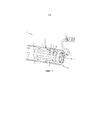
Фиг. 1 изображает измеритель 5 с вибрирующим элементом в соответствии с вариантом воплощения изобретения.FIG. 1 shows a
Фиг. 2 изображает измерительную электронику 20 в соответствии с вариантом воплощения изобретения.FIG. 2 shows
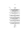
Фиг. 3 изображает способ 300 в соответствии с вариантом воплощения изобретения. FIG. 3 depicts a
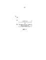
Фиг. 4 изображает способ 400 в соответствии с вариантом воплощения изобретения.FIG. 4 depicts a
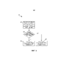
Фиг. 5 изображает способ 500 в соответствии с вариантом воплощения изобретения.FIG. 5 depicts a
Подробное описаниеDetailed description
Фиг. 1-5 и последующее описание изображают конкретные примеры для обучения специалистов в области техники, как сделать и использовать наилучший вариант изобретения. С целью обучения принципам изобретения некоторые известные аспекты были упрощены или опущены. Специалистам в области техники будут понятны вариации этих примеров, которые находятся в пределах объема изобретения. Специалистам в области техники будет понятно, что признаки, описанные ниже, могут сочетаться различным образом для формирования множества вариантов изобретения. В результате изобретение не ограничивается конкретными примерами, описанными ниже, а ограничивается только формулой изобретения и ее эквивалентами.FIG. 1-5 and the following description depict specific examples for training specialists in the field of technology how to make and use the best version of the invention. In order to teach the principles of the invention, several well-known aspects have been simplified or omitted. Variants of these examples, which are within the scope of the invention, will be apparent to those skilled in the art. Those skilled in the art will appreciate that the features described below can be combined in various ways to form a multitude of variations of the invention. As a result, the invention is not limited to the specific examples described below, but is limited only by the claims and their equivalents.
Фиг. 1 показывает измеритель 5 с вибрирующим элементом, измеритель плотности. Измеритель 5 с вибрирующим элементом содержит сборку 10 датчика и измерительную электронику 20. Вариант воплощения измерителя плотности, однако, не является ограничивающим. Специалисты в области техники с легкостью поймут, что варианты воплощения изобретения, описанного в настоящем документе, могут быть применены к проверке измерителей плотности жидкости, измерителей плотности газа, измерителей вязкости жидкости, измерителей специфической плотности газа/жидкости, измерителей относительной плотности газа/жидкости, измерителей молекулярного веса газа и/или любого типа вибрационного измерителя.FIG. 1 shows a
Измеритель 5 с вибрирующим элементом может быть выполнен с возможностью измерять плотность текучей среды, такой как, например, жидкость или газ. Измеритель 5 с вибрирующим элементом включает в себя корпус 11 с вибрирующим элементом 12, расположенным по меньшей мере частично в корпусе 11. Часть корпуса 11 срезана, чтобы показать вибрирующий элемент 12. Измеритель 5 с вибрирующим элементом может быть, например, встроен прямоточным образом в существующем трубопроводе. Альтернативно, корпус 11 может содержать, например, закрытые концы с отверстиями для приема образца текучей среды. Поэтому, хотя фланцы не показаны, во многих случаях корпус 11 или вибрирующий элемент 12 может включать в себя фланцы или другие элементы для функционального соединения измерителя 5 с вибрирующим элементом с трубопроводом или аналогичным устройством доставки текучей среды герметичным образом. В соответствии с показанным примером вибрирующий элемент 12 является кантилевером, закрепленным на корпусе 11. Вибрирующий элемент 12 показан соединенным с корпусом 11 у входного конца 13 со свободно вибрирующим выходным концом 14.The
В соответствии с показанным примером вибрирующий элемент 12 также включает в себя множество отверстий 15 для текучей среды вблизи от входного конца 13. Отверстия 15 для текучей среды могут быть обеспечены для того, чтобы позволять части текучей среды поступать в измеритель 5 с вибрирующим элементом и течь между корпусом 11 и вибрирующим элементом 12. Поэтому текучая среда контактирует как с внутренней, так и с внешней поверхностями вибрирующего элемента 12. Это особенно полезно, когда тестируемая текучая среда содержит газ, потому что большая площадь поверхности подвергается воздействию газа. В других примерах отверстия могут быть обеспечены в корпусе 11, чтобы тестируемая текучая среда воздействовала на наружную поверхность вибрирующего элемента 12, и поэтому нет необходимости в отверстиях 15 в вибрирующем элементе 12.According to the example shown, the vibrating
Дополнительно на фиг. 1 показан драйвер 16 и измерительный преобразователь 17, расположенный в цилиндре 50. Драйвер 16 и измерительный преобразователь 17 показаны включающими в себя катушки, которые хорошо известны в области техники. Если в катушку подается электрический ток, в вибрирующем элементе 12 индуцируется магнитное поле, заставляющее вибрирующий элемент 12 вибрировать. С другой стороны, вибрация вибрирующего элемента 12 индуцирует напряжение в измерительном преобразователе 17. Драйвер 16 принимает возбуждающий сигнал от измерительной электроники 20 для возбуждения вибрации вибрирующего элемента 12 на одной из его резонансных частот в одном из множества типов колебаний, в том числе, например, простом изгибном, крутильном, радиальном или связанном типе. Измерительный преобразователь 17 обнаруживает вибрацию вибрирующего элемента 12, в том числе частоту, с которой вибрирующий элемент 12 вибрирует, и отправляет информацию о вибрации измерительной электронике 20 для обработки. Когда вибрирующий элемент 12 вибрирует, текучая среда, контактирующая со стенкой вибрирующего элемента, вибрирует вместе с вибрирующим элементом 12. Присоединенная масса текучей среды, контактирующей с вибрирующим элементом 12, понижает резонансную частоту. Новая, более низкая резонансная частота вибрирующего элемента 12 используется для определения плотности текучей среды, как общеизвестно в области техники, например, в соответствии с ранее определенной корреляцией.Additionally, in FIG. 1 shows a
Измеритель 5 с вибрирующим элементом дополнительно включает в себя температурный датчик 112. В вариантах воплощения температурный датчик 112 соединен с корпусом 11. Однако в других вариантах воплощения температурный датчик 112 может быть соединен с драйвером 16, измерительным преобразователем 17, входом 13 или любой другой частью сборки 10 датчика. В вариантах воплощения измеритель 5 с вибрирующим элементом может включать в себя более чем один температурный датчик, и каждый соответствующий температурный датчик может быть соединен с одним и тем же или различными компонентами сборки 10 датчика. Один или несколько сигналов, обеспеченных температурными датчиками 112, могут объединяться любым образом, общеизвестным специалистам в области техники, для генерации одного или нескольких значений измерения температуры.The
Фиг. 2 изображает измерительную электронику 20 5 с вибрирующим элементом в соответствии с вариантом воплощения изобретения. Измерительная электроника 20 может включать в себя интерфейс 201 и систему 203 обработки. Система 203 обработки может включать в себя систему 204 памяти. Как обсуждалось ранее, измерительная электроника20 может генерировать возбуждающий сигнал для подачи драйверу 16 и принимать сигналы от измерительного преобразователя 17 и температурного датчика 112. В некоторых вариантах воплощения измерительная электроника 20 может принимать сигналы от драйвера 16. Измерительная электроника 20 может эксплуатировать сборку 10 датчика как измеритель плотности, измеритель вязкости или расходометр, такой как массовый расходомер Кориолиса. Следует принять во внимание, что измерительная электроника 20 может также эксплуатировать другие типы вибрационных измерителей, и конкретные обеспеченные примеры не должны ограничивать объем настоящего изобретения. Измерительная электроника20 может обрабатывать сигналы вибрационного датчика для получения одной или нескольких характеристик материала в корпусе 11.FIG. 2 shows a
Интерфейс 201 может принимать сигналы датчика от драйвера 16, измерительного преобразователя 17 или температурного датчика 112 по проводам. Интерфейс 201 может выполнять любое необходимое или желаемое предварительное формирование сигнала, такое как любой способ форматирования, усиления, буферизации и т.д. Альтернативно, часть или все предварительное формирование сигнала может выполняться в системе 203 обработки. Кроме того, интерфейс 201 может обеспечивать связь между измерительной электроникой20 и внешними устройствами. Интерфейс 201 может быть способен осуществлять любой вид электронной, оптической или беспроводной связи. Кроме того, интерфейс 201 может, например, обеспечивать связь между измерительной электроникой20 и внешними устройствами. Интерфейс 201 может быть способен осуществлять любой вид электронной, оптической или беспроводной связи.Interface 201 may receive sensor signals from
Интерфейс 201 в одном варианте воплощения может включать в себя оцифровщик (не показан), при этом сигналы сборки 10 датчика содержат аналоговые сигналы датчика. Оцифровщик может квантовать и оцифровывать аналоговые сигналы датчика и производить цифровые сигналы датчика. Оцифровщик может также выполнять любое необходимое прореживание, при этом цифровой сигнал датчика прореживается, чтобы уменьшить величину необходимой обработки сигнала и уменьшать время обработки.The interface 201 in one embodiment may include a digitizer (not shown), wherein the signals of the sensor assembly 10 comprise analog sensor signals. The digitizer can quantize and digitize analog sensor signals and produce digital sensor signals. The digitizer can also perform any necessary decimation, while the digital signal of the sensor is decimated to reduce the amount of signal processing required and reduce the processing time.
Система 203 обработки производит операции измерительной электроники 20 и обрабатывает измерения плотности/вязкости/расхода от сборки 10 датчика. Система 203 обработки может также исполнять одну или несколько процедур обработки, таких как процедура 205 проверки датчика.The processing system 203 performs the operations of the
Система 203 обработки может содержать универсальный компьютер, микропроцессорную систему, логическую схему или любое другое универсальное или специализированное устройство обработки, способное выполнять функции, описанные в настоящем документе. Система 203 обработки может быть распределена между несколькими устройствами обработки. Система 203 обработки может включать в себя любой вид интегрального или независимого электронного накопителя данных, такого как система 204 памяти.The processing system 203 may comprise a general purpose computer, microprocessor system, logic circuit, or any other universal or specialized processing device capable of performing the functions described herein. Processing system 203 may be distributed among multiple processing devices. The processing system 203 may include any kind of integrated or independent electronic data storage device, such as a memory system 204.
Система 204 памяти может хранить параметры и данные измерителя, программное обеспечение, величины констант и значения переменных. Система 204 памяти может содержать основную или главную память, такую как память с произвольным доступом (RAM). В вариантах воплощения система 204 памяти может включать в себя привод жесткого диска, съемное запоминающее устройство, карту памяти, привод гибких дисков, привод магнитной ленты, привод компакт-дисков, цифровой универсальный диск, диск Blue-ray, оптическое запоминающее устройство, устройство резервного копирования на магнитную ленту или любой другой накопитель данных, который может использоваться или считываться компьютером.The memory system 204 may store meter parameters and data, software, constant values, and variable values. The memory system 204 may comprise main or main memory, such as random access memory (RAM). In embodiments, the memory system 204 may include a hard disk drive, a removable storage device, a memory card, a floppy disk drive, a magnetic tape drive, a CD drive, a digital versatile disk, a Blue-ray disk, optical storage device, a backup device onto a magnetic tape or any other data storage device that can be used or read by a computer.
Следует понимать, что измерительная электроника 20 может включать в себя различные другие компоненты и функции, которые являются общеизвестными в области техники. Эти дополнительные признаки опущены в описании и на фигурах для краткости. Поэтому настоящее изобретение не должно ограничиваться конкретными показанными и обсуждаемыми вариантами воплощения.It should be understood that the
Хотя фиг. 1 изображает только одну сборку 10 датчика, осуществляющего связь с измерительной электроникой 20, специалистам в области техники будет понятно, что несколько узлов датчиков могут осуществлять связь с измерительной электроникой 20. Кроме того, измерительная электроника 20 может быть способна эксплуатировать множество различных типов датчика. Поэтому важно подтвердить, что конкретные узлы датчиков, осуществляющие связь с измерительной электроникой 20, содержат правильно работающие датчики. Каждая сборка датчика, такая как сборка 10 датчика, осуществляющего связь с измерительной электроникой 20, может иметь соответствующую секцию системы 204 памяти, посвященную проверке работоспособности в воздушной среде, вакууме или текучей среде. Например, если сборка датчика содержит измеритель плотности, как в примере сборки 10 датчика, калибровочные значения могут включать в себя значение периода времени датчика в эталонных условиях. Другие калибровочные значения датчика также предполагаются и включены в объем настоящего изобретения.Although FIG. 1 depicts only one sensor assembly 10 in communication with the
Система 204 памяти хранит переменные, которые могут использоваться процедурой 205 проверки датчика для проверки работоспособности сборки 10 датчика. Например, система 204 памяти хранит множество температур 206 и множество периодов 207 времени датчика. Множество температур 206 может быть определено путем получения временнòй последовательности измерений по меньшей мере от одного температурного датчика 112. Множество периодов 207 времени датчика может быть определено путем возбуждения сборки датчика на его собственной частоте и определения величины, обратной частоте наибольшего отклика. В примере сборки 10 датчика драйвер 16 может заставлять осциллировать вибрирующий элемент 12, генерируя сигналы в измерительном преобразователе 17, которые могут использоваться для определения последовательности периодов времени датчика для сборки 10 датчика. В вариантах воплощения каждая температура из множества температур 206 может соответствовать соответствующему периоду времени датчика из множества периодов 207 времени датчика. Например, каждая соответствующая температура из множества температур 206 и каждый соответствующий период времени датчика из множества периодов 207 времени датчика могут быть измерены с интервалами в 1 секунду в течение периода в 20 секунд.The memory system 204 stores variables that can be used by the sensor test procedure 205 to verify the health of the sensor assembly 10. For example, the memory system 204 stores a plurality of temperatures 206 and a plurality of sensor time periods 207. A plurality of temperatures 206 can be determined by obtaining a time sequence of measurements from at least one
Система 204 памяти также хранит среднюю температуру 208 и средний период 209 времени датчика. Средняя температура 208 может быть определена путем усреднения множества температур 206. Средний период 209 времени датчика может быть определен путем усреднения множества периодов 207 времени датчика.The memory system 204 also stores an average temperature 208 and an average sensor time period 209. The average temperature 208 can be determined by averaging the plurality of temperatures 206. The average sensor time period 209 can be determined by averaging the plurality of sensor time periods 207.
Система 204 памяти также хранит компенсированный период 210 времени датчика. Компенсированный период 210 времени датчика является значением, которое было скорректировано с учетом одного или нескольких физических факторов, которые могут влиять на измерение периода времени датчика, таких как любая комбинация температуры, давления, высоты и плотности.The memory system 204 also stores a compensated sensor time period 210. The compensated sensor time period 210 is a value that has been adjusted for one or more physical factors that may affect the measurement of the sensor time period, such as any combination of temperature, pressure, height and density.
Компенсированный период 210 времени датчика для сборки 10 датчика может быть скомпенсирован с учетом температуры. Например, по меньшей мере один температурный датчик 112 может указывать, что сборка 10 датчика имеет другую температуру, чем эталонная калибровочная температура. В вариантах воплощения эталонная калибровочная температура может быть равна 20°C. Температура может влиять на жесткость сборки 10 датчика, приводя к смещению измеренного периода времени датчика. В варианте воплощения компенсированный период 210 времени датчика может быть определен путем вычисления смещения для среднего периода 209 времени датчика на основании средней температуры 208.The compensated sensor time period 210 for sensor assembly 10 can be compensated for temperature. For example, at least one
В варианте воплощения плотность окружающего воздуха может быть измерена во время проверки работоспособности в воздушной среде. На измеренный период времени датчика могут дополнительно влиять разность атмосферного давления между эталонными условиями на заводе и территории клиента. Разность атмосферного давления между эталонными условиями и территорией клиента могут быть из-за разностей высоты между испытательными площадками. В вариантах воплощения эталонное атмосферное давление может быть равно 101.325 kPa. Колебания давления из-за изменения погоды могут также присутствовать, но они менее значимы, чем изменения давления из-за высоты. Когда проверка работоспособности выполняется с помощью газа, который имеет другое давлением, чем эталонное давление газа, разность в давлении может создать смещение измеренного периода времени датчика.In an embodiment, the density of the surrounding air can be measured during a performance check in the air. The measured time period of the sensor can be further influenced by the difference in atmospheric pressure between the reference conditions at the factory and the customer’s premises. The difference in atmospheric pressure between the reference conditions and the client’s territory may be due to height differences between the test sites. In embodiments, the reference atmospheric pressure may be 101.325 kPa. Pressure fluctuations due to changes in weather may also be present, but they are less significant than changes in pressure due to altitude. When a health check is performed using a gas that has a pressure other than the reference gas pressure, the pressure difference can create a bias of the measured sensor time period.
Система 204 памяти может дополнительно включать в себя высоту 218, измеренную плотность 219, эталонную плотность 220, чувствительность 221 к плотности, разность 222 плотностей, компенсированную эталонную плотность 223 и смещение периода 224 времени из-за плотности. Высота 218 может представлять собой высоту, где установлен датчик. В вариантах воплощения высота 218 может быть введена пользователем и сохранена в системе 204 памяти. Например, высота 218 может быть введена в начале проверки работоспособности, при установке датчика на территории клиента или в любое другое время. В других вариантах воплощения высота 218 может быть принята с помощью электронного сообщения в измерительной электронике 20.The memory system 204 may further include a
Измеренная плотность 219 может быть измерена во время проверки работоспособности с использованием сборки 10 датчика, как было описано выше. Эталонная плотность 220 может быть плотностью, измеренной измерителем 5 с вибрирующим элементом в эталонных условиях с окружающим атмосферным газом. Эталонная плотность 220 может быть скомпенсирована с учетом изменений плотности из-за высоты, температуры и давления для генерации компенсированной эталонной плотности 223:The measured
В приведенном выше уравнении ![]()
![]()
![]()
![]()
![]()
![]()
![]()
![]()
![]()
![]()
![]()
![]()
![]()
![]()
![]()
![]()
![]()
![]()
где h представляет собой высоту испытательной площадки в метрах.where h is the height of the test site in meters.
В дополнительном варианте воплощения измеренная плотность 219 может быть скомпенсирована с учетом эталонной высоты, температуры и давления.In a further embodiment, the measured
Чувствительность 221 к плотности и разность 222 плотностей может использоваться для вычисления смещения 224 периода времени из-за плотности. Разность 222 плотностей представляет собой разность между компенсированной эталонной плотностью 223 и измеренной плотностью 219. Однако изобретение не ограничивается этим. В других вариантах воплощения разность 222 плотностей может представлять собой разность между эталонной плотностью и измеренной плотностью, скомпенсированную с учетом эталонной высоты, давления и температуры.A
Чувствительность 221 к плотности является мерой точности измерителя в зависимости от материала в измерителе и определяется следующим образом для измерителя плотности вилочного типа:The
Чувствительность к плотности = K1+2×K2×(скомпенсированный с учетом температуры период времени датчика). Density sensitivity = K 1 + 2 × K 2 × (temperature compensated sensor time period).
Чувствительность 221 к плотности определяется следующим образом для измерителя плотности газа:A
Чувствительность к плотности = 2×K2×(скомпенсированный с учетом температуры период времени датчика). Density sensitivity = 2 × K 2 × (temperature compensated sensor time period).
В обоих вышеупомянутых уравнениях для чувствительности к плотности K1 и K2 представляют собой калибровочные константы, которые могут быть определены во время процесса калибровки измерителя. Например, K1 и K2 могут быть определены с помощью процесса калибровки с использованием двух различных текучих среды, которые имеют плотность, известную с высокой точностью.In both of the above equations for density sensitivity, K 1 and K 2 are calibration constants that can be determined during the calibration process of the meter. For example, K 1 and K 2 can be determined using a calibration process using two different fluids that have a density known with high accuracy.
Смещение 224 периода времени из-за плотности является смещением, которое может быть приписано разности плотностей текучих сред при проверке работоспособности и плотности этой текучей среды в эталонных условиях. Смещение 224 периода времени из-за плотности может быть определено с помощью следующего уравнения:The offset 224 of the time period due to the density is the offset that can be attributed to the difference in density of the fluids when checking the operability and density of this fluid under reference conditions. The offset 224 of the time period due to the density can be determined using the following equation:

В вариантах воплощения смещение 224 периода времени из-за плотности может использоваться для дополнительной компенсации компенсированного периода 210 времени датчика. В других вариантах воплощения смещение 224 периода времени из-за плотности может использоваться для компенсации среднего периода 209 времени датчика или любого из множества периодов 207 времени датчика.In embodiments, the offset 224 of the time period due to density can be used to further compensate for the compensated sensor time period 210. In other embodiments, density offset 224 may be used to compensate for an average sensor time period 209 or any of a plurality of sensor time periods 207.
Система 204 памяти может дополнительно хранить эталонный период 211 времени датчика и предел 212 временнòй ошибки датчика. В вариантах воплощения эталонный период 211 времени датчика может быть измерен на заводе в эталонных условиях, прежде чем сборка датчика будет поставлена клиенту. В других вариантах воплощения эталонный период 211 времени датчика может представлять собой эталонное значение, определенное, когда измеритель установлен или сконфигурирован на территории клиента. Эталонный период 211 времени датчика может соответствовать эталонному давлению, температуре, высоте и/или плотности текучей среды. В варианте воплощения эталонный период 211 времени датчика может быть определен с помощью вибрирующих элементов датчика, заполненного окружающим газом на уровне моря. В других вариантах воплощения эталонный период 211 времени датчика может быть определен с помощью вибрирующих элементов датчика в вакууме. В дополнительных вариантах воплощения эталонный период 211 времени датчика может быть определен при любой комбинации температуры и давления и может включать в себя любую эталонную среду. Например, в качестве эталонной среды может использоваться вода.The memory system 204 may further store a sensor reference time period 211 and a sensor error time limit 212. In embodiments, the sensor reference time period 211 may be measured at the factory under reference conditions before the sensor assembly is delivered to the customer. In other embodiments, the reference time period 211 of the sensor may be a reference value determined when the meter is installed or configured at the customer premises. The reference time period 211 of the sensor may correspond to a reference pressure, temperature, height and / or density of the fluid. In an embodiment, the sensor reference time period 211 can be determined using vibrating sensor elements filled with ambient gas at sea level. In other embodiments, the reference time period 211 of the sensor can be determined using vibrating sensor elements in a vacuum. In further embodiments, the reference time period 211 of the sensor may be determined at any combination of temperature and pressure and may include any reference medium. For example, water may be used as a reference medium.
Предел 212 временнòй ошибки датчика представляет собой максимальную допустимую разность между эталонным периодом 211 времени датчика и компенсированным периодом 210 времени датчика, допустимую для обеспечения определения правильности работы датчика измерителя.The sensor error time limit 212 is the maximum allowable difference between the sensor reference period 211 and the compensated sensor time period 210, which is valid to ensure that the meter sensor is operating correctly.
Система 204 памяти может дополнительно включать в себя индикатор 225 правильности работы датчика. Индикатор 225 правильности работы датчика может быть задан после определения, меньше ли разность между компенсированным периодом 210 времени датчика и эталонным периодом 211 времени датчика, чем предел 212 временнòй ошибки датчика. Индикатор 225 правильности работы датчика может указывать, может ли сборка 10 датчика обеспечивать точные измерения массового расхода, плотности, вязкости или какого-либо другого измерения. В вариантах воплощения измерительная электроника 20 может указывать статус индикатора 225 правильности работы датчика путем переключения лампочки или дисплея на измерителе 5 с вибрирующим элементом. В других вариантах воплощения измерительная электроника 20 может указывать, что сборка 10 датчика работает правильно, путем отправки электронного отчета другому вычислительному устройству.The memory system 204 may further include an indicator 225 for proper sensor operation. The indicator 225 of the correct operation of the sensor can be set after determining whether the difference between the compensated period 210 of the sensor time and the reference period 211 of the sensor is less than the limit 212 of the time error of the sensor. The sensor 225 indicator of correct operation may indicate whether the sensor assembly 10 can provide accurate measurements of mass flow, density, viscosity, or some other measurement. In embodiments, the
При определении правильности работы сборки датчика с помощью существующих методологий проверки работоспособности стабильность датчика может обеспечивать дополнительное ограничение для получения точных результатов. Измеритель, который находится в нестабильном или не установившемся состоянии, может обеспечить измерения периода времени датчика, которые отклоняются в широком диапазоне значений, обеспечивая ложные результаты. Система 204 памяти дополнительно включает в себя среднеквадратичное отклонение 213 температуры, среднеквадратичное отклонение 214 периода времени датчика, предел 215 среднеквадратичного отклонения периода времени датчика, предел 216 среднеквадратичного отклонения температуры и индикатор 217 стабильности состояния для преодоления этого возможного ограничения. Среднеквадратичное отклонение 213 температуры представляет собой среднеквадратичное отклонение множества температур 206. Среднеквадратичное отклонение 214 периода времени датчика представляет собой среднеквадратичное отклонение множества периодов 207 времени датчика.When determining the correct assembly of a sensor assembly using existing health testing methodologies, sensor stability may provide an additional limitation to obtain accurate results. A meter that is in an unstable or unsteady state can provide measurements of the sensor's time period, which deviate over a wide range of values, providing false results. The memory system 204 further includes a standard deviation 213 of the temperature, a standard deviation 214 of the sensor time period, a limit 215 of standard deviation of the sensor time period, a limit 216 of standard deviation of the temperature, and a
Предел 216 среднеквадратичного отклонения температуры может представлять собой максимальное среднеквадратичное отклонение 213 температуры, которое может указывать стабильный датчик. Среднеквадратичное отклонение 213 температуры может повыситься, когда температура сборки 10 датчика изменяется быстро. Когда среднеквадратичное отклонение 213 температуры больше, чем предел 216 среднеквадратичного отклонения температуры, вибрационный измеритель может не иметь возможности обеспечить надежные измерения, и проверка работоспособности не может привести к точным результатам.The temperature standard deviation limit 216 may be the maximum standard deviation 213 of the temperature, which may indicate a stable sensor. The standard deviation 213 of the temperature may increase when the temperature of the sensor assembly 10 changes rapidly. When the standard deviation 213 of the temperature is greater than the limit 216 of the standard deviation of the temperature, the vibration meter may not be able to provide reliable measurements, and a performance check may not lead to accurate results.
Среднеквадратичное отклонение 214 периода времени датчика может повыситься в силу многих причин, в том числе когда условия окружающей среды или тестирования изменяются быстро. Предел 215 среднеквадратичного отклонение периода времени датчика может представлять собой максимальное среднеквадратичное отклонение периода времени датчика, которое может указать стабильный датчик. Когда среднеквадратичное отклонении 214 периода времени датчика больше, чем предел 215 среднеквадратичного отклонения период времени датчика, тогда вибрационный измеритель может не иметь возможности обеспечить надежные измерения, и проверка работоспособности не может привести к точным результатам.The standard deviation 214 of the sensor time period can increase for many reasons, including when environmental or testing conditions change rapidly. The limit 215 of the standard deviation of the sensor time period may be the maximum standard deviation of the sensor time period, which can indicate a stable sensor. When the standard deviation 214 of the sensor time period is greater than the limit 215 of the standard deviation of the sensor time period, then the vibration meter may not be able to provide reliable measurements, and the performance check may not lead to accurate results.
Индикатор 217 стабильности состояния может указывать, определено ли, что датчик стабилен. В вариантах воплощения индикатор 217 стабильности состояния может быть указан на лампочке или другом дисплее для пользователя. В других вариантах воплощения индикатор 217 стабильности состояния может быть отправлен через электронный отчет другому вычислительному устройству.The
В варианте воплощения система 204 памяти включает в себя процедуры, которые исполняются системой 203 обработки. Например, система 204 памяти хранит процедуру 205 проверки датчика. Измерительная электроника 20 может инициировать и управлять процедурой 205 проверки датчика для проверки сборки 10 датчика. В вариантах воплощения процедура 205 проверки датчика может выполнять проверку работоспособности для определения правильности работы сборки датчика и указывать результаты с помощью индикатора 225 правильности работы датчика, используя способы, обсуждавшиеся выше. В других вариантах воплощения процедура 205 проверки датчика может определять, обеспечивает ли сборка 10 датчика стабильные измерения, и указывать результаты с помощью индикатора 217 стабильности состояния, как было описано выше.In an embodiment, the memory system 204 includes procedures that are executed by the processing system 203. For example, the memory system 204 stores a sensor check procedure 205. The
Фиг. 3-5 изображают, соответственно, способы 300, 400 и 500 проверки датчика. Способы 300, 400 и 500 проверки датчика представляют собой иллюстративные варианты воплощения процедуры 205 проверки датчика. Система 203 обработки может быть выполнена с возможностью выполнения необходимой обработки сигнала и данных для исполнения процедуры 205 проверки датчика, которая может включать в себя выполнение любой комбинации способов 300, 400 и 500 проверки датчика.FIG. 3-5 depict, respectively,
Способ 300 проверки датчика на фиг. 3 начинается с этапа 302. На этапе 302 измеряется множество температур с использованием по меньшей мере одного температурного датчика, и измеряется множество периодов времени датчика с использованием сборки 10 датчика. Например, множество температур 206 может быть измерено с использованием температурного датчика 112. В вариантах воплощения множество температур 206 может быть измерено с использованием более чем одного температурного датчика, соединенного с любой частью сборки 10 датчика. Множество периодов 207 времени датчика может быть определено с помощью вибрирующего драйвера 16 и приема вибрационного отклика с помощью измерительного преобразователя 17 в измерительной электронике 20.The
В вариантах воплощения этап 302 может дополнительно включать в себя очистку сборки 10 датчика. Например, внутренняя или внешняя часть корпуса 11, вибрирующий элемент 12, входной конец 13, отверстия 15 для текучей среды, драйвер 16, измерительный преобразователь 17 или цилиндр 50 могут очищаться с помощью растворителя или любым другим способом, являющимся общеизвестным специалистам в области техники.In embodiments,
В вариантах воплощения этап 302 может дополнительно включать в себя заполнение сборки 10 датчика окружающим воздухом.In embodiments,
В вариантах воплощения этап 302 может дополнительно включать в себя помещение сборки 10 датчика в вакуум.In embodiments,
В вариантах воплощения этап 302 может дополнительно включать в себя заполнение сборки 10 датчика текучей средой, имеющей точно известную плотность. Например, сборка датчика может заполняться водой.In embodiments,
Способ 300 продолжается на этапе 304. На этапе 304 определяется средняя температура по множеству температур. Например, средняя температура 208 может быть определена путем усреднения множества температур 206, как было описано выше.
Способ 300 продолжается на этапе 306. На этапе 306 определяется средний период времени датчика по множеству периодов времени датчика. Например, средний период 209 времени датчика может быть определен путем усреднения множества периодов 207 времени датчика, как было описано выше.
Способ 300 продолжается на этапе 308. На этапе 308 средний период времени датчика компенсируются с использованием средней температуры для генерации компенсированного периода времени датчика. Например, средний период 209 времени датчика может быть скомпенсирован с использованием средней температуры 208 для генерации компенсированного периода 210 времени датчика, как было описано выше.
Способ 300 продолжается на этапе 310. На этапе 310 компенсированный период времени датчика сравнивается с эталонным периодом времени датчика. Например, компенсированный период 210 времени датчика может сравниваться с эталонным периодом 211 времени датчика, как было описано выше.
Способ 300 продолжается на этапе 312. На этапе 312 указывается, не превышает ли компенсированный период времени датчика предел ошибки периода времени датчика эталонного периода времени датчика. Например, может указываться, не превышает ли компенсированный период 210 времени датчика предел 212 временнòй ошибки датчика эталонного периода 211 времени датчика, как было описано выше.The
В вариантах воплощения в дополнение к способу 300 может выполняться способ 400 проверки датчика. Способ 400 на фиг. 4 начинается с этапа 402. На этапе 402 принимается значение высоты. Высота является высотой местоположения датчика над уровнем моря. Например, может быть принята высота 218, как было описано выше.In embodiments, in addition to
Способ 400 продолжается на этапе 404. На этапе 404 компенсированный период времени датчика компенсируется с использованием высоты. Например, компенсированный период 210 времени датчика может быть скомпенсирован с использованием высоты 218, как было описано выше.
В вариантах воплощения этап 404 может дополнительно включать в себя измерение плотности текучей среды с использованием сборки датчика и компенсацию компенсированного периода времени датчика с учетом разности плотностей между эталонной плотностью и измеренной плотностью с использованием высоты. Например, измеренная плотность 219 может быть измерена с использованием сборки 10 датчика. Высота 218 может использоваться для компенсации любого из множества периодов 207 времени датчика, среднего периода 209 времени датчика или компенсированного периода 210 времени датчика, как было описано выше.In embodiments,
В вариантах воплощения в дополнение к способам 300 и/или 400 может выполняться способ 500 проверки датчика. Как изображено на фиг. 5, способ 500 начинается с этапа 502. На этапе 502 вычисляется среднеквадратичное отклонение с использованием одного из: множества температур или множества периодов времени датчика. Например, среднеквадратичное отклонение 213 температуры может быть вычислено с использованием множества температур 206, или среднеквадратичное отклонение 214 периода времени датчика может быть вычислено с использованием множества периодов 207 времени датчика, как было описано выше.In embodiments, in addition to
Способ 500 продолжается на этапе 504. На этапе 504 определяется, больше ли среднеквадратичное отклонение, чем предел. Например, может быть определено, больше ли среднеквадратичное отклонение 213 температуры, чем предел 216 среднеквадратичного отклонения температура, или может быть определено, больше ли среднеквадратичное отклонение 214 периода времени датчика, чем предел 215 среднеквадратичного отклонения периода времени датчика, как было описано выше. В вариантах воплощения способ 500 может быть выполнен дважды путем вычисления каждого из: среднеквадратичного отклонения 213 температуры и среднеквадратичного отклонения 214 периода времени датчика.The
Если на этапе 504 было определено, что среднеквадратичное отклонение больше, чем предел, способ 500 продолжается на этапе 506. Если на этапе 504 было определено, что среднеквадратичное отклонение не превышает предел, способ 500 продолжается на этапе 508. На этапе 506 указывается, что состояние является нестабильным. На этапе 508 указывается, что состояние является стабильным. Например, индикатор 217 стабильности состояния может использоваться для указания, стабильно ли состояние сборки 10 датчика. В варианте воплощения измерительная электроника20 может указывать, устойчиво ли состояние, путем переключения индикаторной лампочки или иного обеспечения отображения для пользователя. В другом варианте воплощения измерительная электроника20 может указывать, устойчиво ли состояние, путем отправления электронного отчета. Другие способы указания стабильности сборки 10 датчика также предусматриваются этим изобретением, как будет понятно специалистам в области техники.If at
Подробные описания вышеупомянутых вариантов воплощения не являются исчерпывающими описаниями всех вариантов воплощения, которые находятся в пределах объема изобретения, как это предполагается авторами изобретения. Действительно, специалистам в области техники будет понятно, что определенные элементы вышеописанных вариантов воплощения могут быть по-разному скомбинированы или убраны для создания дополнительных вариантов воплощения, и такие дополнительные варианты воплощения попадают в рамки объема и идей изобретения. Специалистам в области техники также будет очевидно, что вышеописанные варианты воплощения могут быть объединены целиком или частично для создания дополнительных вариантов воплощения в пределах объема и идей изобретения.Detailed descriptions of the above embodiments are not exhaustive descriptions of all embodiments that are within the scope of the invention, as intended by the inventors. Indeed, it will be understood by those skilled in the art that certain elements of the above described embodiments may be combined or removed in different ways to create additional embodiments, and such additional embodiments fall within the scope and spirit of the invention. It will also be apparent to those skilled in the art that the above described embodiments may be combined in whole or in part to create additional embodiments within the scope and ideas of the invention.
Таким образом, хотя конкретные варианты воплощения и примеры изобретения описаны в настоящем документе с иллюстративными целями, в рамках объема изобретения возможны различные эквивалентные модификации, как будет понятно специалистам в соответствующей области техники. Идеи, обеспеченные в настоящем документе, могут быть применены к другим измерителям, а не только к вариантам воплощения, описанным выше и показанным на прилагаемых фигурах. Соответственно, объем изобретения должен определяться прилагаемой формулой изобретения.Thus, although specific embodiments and examples of the invention are described herein for illustrative purposes, various equivalent modifications are possible within the scope of the invention, as will be appreciated by those skilled in the art. The ideas provided herein can be applied to other meters, and not just to the embodiments described above and shown in the accompanying figures. Accordingly, the scope of the invention should be determined by the attached claims.
Claims (48)
Applications Claiming Priority (3)
| Application Number | Priority Date | Filing Date | Title |
|---|---|---|---|
| US201361813495P | 2013-04-18 | 2013-04-18 | |
| US61/813,495 | 2013-04-18 | ||
| PCT/US2014/032806 WO2014172111A1 (en) | 2013-04-18 | 2014-04-03 | Verification of a meter sensor for a vibratory meter |
Publications (1)
| Publication Number | Publication Date |
|---|---|
| RU2619829C1 true RU2619829C1 (en) | 2017-05-18 |
Family
ID=50631113
Family Applications (1)
| Application Number | Title | Priority Date | Filing Date |
|---|---|---|---|
| RU2015148957A RU2619829C1 (en) | 2013-04-18 | 2014-04-03 | Test of sensing element for vibration meter |
Country Status (13)
| Country | Link |
|---|---|
| US (1) | US10215677B2 (en) |
| EP (2) | EP3035028B1 (en) |
| JP (2) | JP6498180B2 (en) |
| KR (1) | KR101920832B1 (en) |
| CN (1) | CN105339776B (en) |
| AR (1) | AR096033A1 (en) |
| AU (1) | AU2014254365B2 (en) |
| BR (1) | BR112015026190B1 (en) |
| CA (2) | CA2963109C (en) |
| MX (1) | MX363154B (en) |
| RU (1) | RU2619829C1 (en) |
| SG (3) | SG10201704205PA (en) |
| WO (1) | WO2014172111A1 (en) |
Families Citing this family (10)
| Publication number | Priority date | Publication date | Assignee | Title |
|---|---|---|---|---|
| WO2016014053A1 (en) * | 2014-07-23 | 2016-01-28 | Halliburton Energy Services, Inc. | Thermal modulated vibrating sensing module for gas molecular weight detection |
| WO2016109447A1 (en) * | 2014-12-29 | 2016-07-07 | Concentric Meter Corporation | Fluid parameter sensor and meter |
| US10126266B2 (en) | 2014-12-29 | 2018-11-13 | Concentric Meter Corporation | Fluid parameter sensor and meter |
| WO2016109451A1 (en) | 2014-12-29 | 2016-07-07 | Concentric Meter Corporation | Electromagnetic transducer |
| EP3268703B1 (en) | 2015-03-13 | 2023-07-12 | Micro Motion, Inc. | Temperature compensation of a signal in a vibratory flowmeter |
| DE102015111686A1 (en) * | 2015-07-17 | 2017-01-19 | Krohne Messtechnik Gmbh | A method of operating a Coriolis mass flowmeter and Coriolis mass flowmeter in this regard |
| DE102016103048B3 (en) * | 2016-02-22 | 2017-04-20 | Krohne Messtechnik Gmbh | Method of operating a Coriolis mass flowmeter |
| US11353510B1 (en) * | 2020-12-28 | 2022-06-07 | Endress+Hauser Flowtec Ag | Method for testing a device under test |
| CN113658353B (en) * | 2021-07-07 | 2023-05-16 | 中国人民解放军海军航空大学青岛校区 | Airborne Integrated Collector |
| US20250020562A1 (en) * | 2023-07-15 | 2025-01-16 | Honeywell International Inc. | Improving accuracy by adding additional sensors to a density measuring system |
Citations (6)
| Publication number | Priority date | Publication date | Assignee | Title |
|---|---|---|---|---|
| US20010045134A1 (en) * | 2000-03-23 | 2001-11-29 | Henry Manus P. | Correcting for two-phase flow in a digital flowmeter |
| RU2177610C2 (en) * | 1996-07-16 | 2001-12-27 | Майкро Моушн, Инк. | Method and gear to determine density of material flowing through flowmeter |
| US20070186684A1 (en) * | 2003-07-24 | 2007-08-16 | Pham Nghieu Q | Vibrating tube mass flow meter |
| RU2320964C2 (en) * | 2002-12-06 | 2008-03-27 | Эндресс+Хаузер Флоутек Аг | Device for measuring physical parameters |
| US20110203388A1 (en) * | 2010-02-19 | 2011-08-25 | Hirokazu Kitami | Signal processing method, signal processing apparatus, and coriolis flowmeter |
| US8151653B2 (en) * | 2009-07-16 | 2012-04-10 | Yokogawa Electric Corporation | Coriolis flowmeter |
Family Cites Families (24)
| Publication number | Priority date | Publication date | Assignee | Title |
|---|---|---|---|---|
| FR1296208A (en) * | 1961-07-26 | 1962-06-15 | Method and device for the detection of butane or other heavy gases in the free state in closed rooms | |
| US3902355A (en) | 1972-07-31 | 1975-09-02 | Gauting Gmbh Apparatebau | Apparatus for the electronic-digital measurement of gas pressure |
| GB8525781D0 (en) * | 1985-10-18 | 1985-11-20 | Schlumberger Electronics Uk | Transducers |
| US4734609A (en) * | 1986-07-25 | 1988-03-29 | Calogic Corporation | Gas density transducer |
| EP0342505B1 (en) * | 1988-05-17 | 1992-02-26 | Aran Engineering Development Ltd | Portable weighing scale |
| GB9208704D0 (en) * | 1992-04-22 | 1992-06-10 | Foxboro Ltd | Improvements in and relating to sensor units |
| US6526839B1 (en) * | 1998-12-08 | 2003-03-04 | Emerson Electric Co. | Coriolis mass flow controller and capacitive pick off sensor |
| CA2720501C (en) | 2000-08-18 | 2015-09-22 | Emerson Electric Co. | Coriolis mass flow controller |
| CN2645054Y (en) * | 2003-04-11 | 2004-09-29 | 广州发电厂 | Vibration instrument gauging apparatus |
| WO2005040733A1 (en) | 2003-09-29 | 2005-05-06 | Micro Motion, Inc. | Method for detecting corrosion, erosion or product buildup on vibrating element densitometers and coriolis flowmeters and calibration validation |
| US7337084B2 (en) | 2005-06-21 | 2008-02-26 | Invensys Systems, Inc. | Switch-activated zero checking feature for a Coriolis flowmeter |
| EP1925916A3 (en) | 2005-07-11 | 2011-08-03 | Invensys Systems, Inc. | Coriolis mode processing techniques |
| CA2622976C (en) * | 2005-09-19 | 2013-05-07 | Micro Motion, Inc. | Meter electronics and methods for verification diagnostics for a flow meter |
| US9341059B2 (en) | 2009-04-15 | 2016-05-17 | Schlumberger Technology Corporation | Microfluidic oscillating tube densitometer for downhole applications |
| BRPI1011179B1 (en) * | 2009-07-13 | 2020-05-19 | Micro Motion Inc | meter electronics, and fluid quantification method for a fluid being transferred |
| JP5534182B2 (en) * | 2010-03-18 | 2014-06-25 | セイコーエプソン株式会社 | Measuring system and measuring method of frequency temperature characteristic of vibration device |
| CN201672968U (en) * | 2010-05-14 | 2010-12-15 | 成都赛腾自动化工程有限公司 | Adaptive signal adjusting device for vibrating sensor |
| RU2545323C1 (en) * | 2011-02-23 | 2015-03-27 | Майкро Моушн, Инк. | Vibration flowmeter and temperature measurement method |
| US9383241B2 (en) * | 2011-07-07 | 2016-07-05 | Micro Motion, Inc. | Method and apparatus for determining differential flow characteristics of a multiple meter fluid flow system |
| EP2565594A1 (en) | 2011-07-11 | 2013-03-06 | Invensys Systems, Inc. | Coriolis flowmeter with zero checking feature |
| BR112014000510B1 (en) | 2011-07-13 | 2020-03-31 | Micro Motion, Inc | VIBRATORY METER, AND, METHOD OF DETERMINING RESONANT FREQUENCY IN THE SAME |
| US9644796B2 (en) * | 2011-09-29 | 2017-05-09 | Applied Materials, Inc. | Methods for in-situ calibration of a flow controller |
| EP3194902B1 (en) * | 2014-09-18 | 2020-09-16 | Micro Motion, Inc. | Method and apparatus for determining differential density |
| US9689736B2 (en) * | 2014-10-31 | 2017-06-27 | Invensys Systems, Inc. | Method to provide a quality measure for meter verification results |
-
2014
- 2014-04-03 US US14/778,958 patent/US10215677B2/en active Active
- 2014-04-03 CA CA2963109A patent/CA2963109C/en active Active
- 2014-04-03 JP JP2016508955A patent/JP6498180B2/en active Active
- 2014-04-03 CA CA2908036A patent/CA2908036C/en active Active
- 2014-04-03 BR BR112015026190-6A patent/BR112015026190B1/en active IP Right Grant
- 2014-04-03 SG SG10201704205PA patent/SG10201704205PA/en unknown
- 2014-04-03 EP EP16150406.3A patent/EP3035028B1/en active Active
- 2014-04-03 AU AU2014254365A patent/AU2014254365B2/en active Active
- 2014-04-03 SG SG10201605528PA patent/SG10201605528PA/en unknown
- 2014-04-03 SG SG11201508323XA patent/SG11201508323XA/en unknown
- 2014-04-03 WO PCT/US2014/032806 patent/WO2014172111A1/en not_active Ceased
- 2014-04-03 RU RU2015148957A patent/RU2619829C1/en active
- 2014-04-03 KR KR1020157032855A patent/KR101920832B1/en active Active
- 2014-04-03 CN CN201480021594.2A patent/CN105339776B/en active Active
- 2014-04-03 MX MX2015014052A patent/MX363154B/en unknown
- 2014-04-03 EP EP14721171.8A patent/EP2986964B1/en active Active
- 2014-04-15 AR ARP140101592A patent/AR096033A1/en active IP Right Grant
-
2017
- 2017-07-06 JP JP2017132500A patent/JP6707059B2/en active Active
Patent Citations (6)
| Publication number | Priority date | Publication date | Assignee | Title |
|---|---|---|---|---|
| RU2177610C2 (en) * | 1996-07-16 | 2001-12-27 | Майкро Моушн, Инк. | Method and gear to determine density of material flowing through flowmeter |
| US20010045134A1 (en) * | 2000-03-23 | 2001-11-29 | Henry Manus P. | Correcting for two-phase flow in a digital flowmeter |
| RU2320964C2 (en) * | 2002-12-06 | 2008-03-27 | Эндресс+Хаузер Флоутек Аг | Device for measuring physical parameters |
| US20070186684A1 (en) * | 2003-07-24 | 2007-08-16 | Pham Nghieu Q | Vibrating tube mass flow meter |
| US8151653B2 (en) * | 2009-07-16 | 2012-04-10 | Yokogawa Electric Corporation | Coriolis flowmeter |
| US20110203388A1 (en) * | 2010-02-19 | 2011-08-25 | Hirokazu Kitami | Signal processing method, signal processing apparatus, and coriolis flowmeter |
Also Published As
| Publication number | Publication date |
|---|---|
| WO2014172111A1 (en) | 2014-10-23 |
| EP3035028A1 (en) | 2016-06-22 |
| US10215677B2 (en) | 2019-02-26 |
| CN105339776A (en) | 2016-02-17 |
| SG10201605528PA (en) | 2016-08-30 |
| CA2963109A1 (en) | 2014-10-23 |
| CA2908036A1 (en) | 2014-10-23 |
| BR112015026190B1 (en) | 2020-11-17 |
| SG11201508323XA (en) | 2015-11-27 |
| MX2015014052A (en) | 2016-02-10 |
| CN105339776B (en) | 2019-05-31 |
| EP2986964B1 (en) | 2019-11-06 |
| AU2014254365B2 (en) | 2017-06-15 |
| JP2017207504A (en) | 2017-11-24 |
| AU2014254365A1 (en) | 2015-12-03 |
| KR20160002948A (en) | 2016-01-08 |
| MX363154B (en) | 2019-03-13 |
| JP6498180B2 (en) | 2019-04-10 |
| SG10201704205PA (en) | 2017-06-29 |
| CA2908036C (en) | 2019-08-20 |
| JP2016522888A (en) | 2016-08-04 |
| HK1221506A1 (en) | 2017-06-02 |
| JP6707059B2 (en) | 2020-06-10 |
| KR101920832B1 (en) | 2018-11-21 |
| EP2986964A1 (en) | 2016-02-24 |
| BR112015026190A2 (en) | 2017-07-25 |
| CA2963109C (en) | 2020-07-21 |
| EP3035028B1 (en) | 2020-07-08 |
| AR096033A1 (en) | 2015-12-02 |
| US20160061707A1 (en) | 2016-03-03 |
Similar Documents
| Publication | Publication Date | Title |
|---|---|---|
| RU2619829C1 (en) | Test of sensing element for vibration meter | |
| US11435219B2 (en) | Method for ascertaining at least one pipe wall resonance frequency, as well as clamp-on, ultrasonic, flow measuring device | |
| RU2487322C1 (en) | Method and device to detect flow error in vibration flow metre | |
| JP5603412B2 (en) | Heterogeneous fluid density measuring device | |
| RU2602733C1 (en) | Detection of change of cross section area of flow-measuring fluid pipeline of vibration meter by determining rigidity of transverse mode | |
| US6732570B2 (en) | Method and apparatus for measuring a fluid characteristic | |
| JP2008510991A (en) | Method and apparatus for verifying a flow meter | |
| US20160103053A1 (en) | Method and device for determining the filling quality of a frequency oscillator | |
| CN113260834A (en) | Method for determining physical parameters of carrier gas liquid | |
| JP6739616B2 (en) | Method for Performing Temperature Compensation for Maximum Sensor Current and Test Tone Amplitude During Meter Verification | |
| US20020189323A1 (en) | Method and apparatus for measuring a fluid characteristic | |
| JP2015072284A (en) | Method and apparatus for determining zero offset in vibrating flow meter | |
| KR102840490B1 (en) | Method and device for calculating vibration system Q | |
| HK1221506B (en) | Verification of a meter sensor for a vibratory meter | |
| CN108398167B (en) | Method for measuring pressure and coriolis mass flowmeter | |
| RU2806622C1 (en) | Method and device for calculating quality factor q of vibration measuring device | |
| CN109579973A (en) | A kind of vibrating speed sensors sensitivity coefficient method of calibration | |
| RU2803043C1 (en) | Method for assessing the state of a coriolis flowmeter for its verification and/or disagnostics | |
| RU2323418C1 (en) | Identification of type of flowmeter | |
| JP2021533346A (en) | Electronic measuring instrument for flowmeter and verification diagnostic method | |
| HK40005850A (en) | Method for performing temperature compensation of maximum sensor current and test tone amplitude during meter verification |