RU2625730C2 - Dispensing device and method of repeated filling of the dispensing device - Google Patents
Dispensing device and method of repeated filling of the dispensing device Download PDFInfo
- Publication number
- RU2625730C2 RU2625730C2 RU2015153826A RU2015153826A RU2625730C2 RU 2625730 C2 RU2625730 C2 RU 2625730C2 RU 2015153826 A RU2015153826 A RU 2015153826A RU 2015153826 A RU2015153826 A RU 2015153826A RU 2625730 C2 RU2625730 C2 RU 2625730C2
- Authority
- RU
- Russia
- Prior art keywords
- cartridge
- housing
- dispensing device
- sheets
- sheet material
- Prior art date
Links
Images

Classifications
-
- A—HUMAN NECESSITIES
- A47—FURNITURE; DOMESTIC ARTICLES OR APPLIANCES; COFFEE MILLS; SPICE MILLS; SUCTION CLEANERS IN GENERAL
- A47K—SANITARY EQUIPMENT; ACCESSORIES THEREFOR, e.g. TOILET ACCESSORIES
- A47K10/00—Body-drying implements; Toilet paper; Holders therefor
- A47K10/24—Towel dispensers; Toilet paper dispensers
- A47K10/32—Dispensers for paper towels or toilet paper
- A47K10/42—Dispensers for paper towels or toilet paper dispensing from a store of single sheets, e.g. stacked
- A47K10/421—Dispensers for paper towels or toilet paper dispensing from a store of single sheets, e.g. stacked dispensing from the top of the dispenser
- A47K10/422—Dispensers for paper towels or toilet paper dispensing from a store of single sheets, e.g. stacked dispensing from the top of the dispenser with means for urging the whole stack upwards towards the dispensing opening, e.g. a spring, a counterweight
-
- B—PERFORMING OPERATIONS; TRANSPORTING
- B65—CONVEYING; PACKING; STORING; HANDLING THIN OR FILAMENTARY MATERIAL
- B65B—MACHINES, APPARATUS OR DEVICES FOR, OR METHODS OF, PACKAGING ARTICLES OR MATERIALS; UNPACKING
- B65B25/00—Packaging other articles presenting special problems
- B65B25/14—Packaging paper or like sheets, envelopes, or newspapers, in flat, folded, or rolled form
-
- B—PERFORMING OPERATIONS; TRANSPORTING
- B65—CONVEYING; PACKING; STORING; HANDLING THIN OR FILAMENTARY MATERIAL
- B65B—MACHINES, APPARATUS OR DEVICES FOR, OR METHODS OF, PACKAGING ARTICLES OR MATERIALS; UNPACKING
- B65B5/00—Packaging individual articles in containers or receptacles, e.g. bags, sacks, boxes, cartons, cans, jars
- B65B5/06—Packaging groups of articles, the groups being treated as single articles
-
- A—HUMAN NECESSITIES
- A47—FURNITURE; DOMESTIC ARTICLES OR APPLIANCES; COFFEE MILLS; SPICE MILLS; SUCTION CLEANERS IN GENERAL
- A47K—SANITARY EQUIPMENT; ACCESSORIES THEREFOR, e.g. TOILET ACCESSORIES
- A47K10/00—Body-drying implements; Toilet paper; Holders therefor
- A47K10/24—Towel dispensers; Toilet paper dispensers
- A47K10/32—Dispensers for paper towels or toilet paper
- A47K2010/3233—Details of the housing, e.g. hinges, connection to the wall
-
- A—HUMAN NECESSITIES
- A47—FURNITURE; DOMESTIC ARTICLES OR APPLIANCES; COFFEE MILLS; SPICE MILLS; SUCTION CLEANERS IN GENERAL
- A47K—SANITARY EQUIPMENT; ACCESSORIES THEREFOR, e.g. TOILET ACCESSORIES
- A47K10/00—Body-drying implements; Toilet paper; Holders therefor
- A47K10/24—Towel dispensers; Toilet paper dispensers
- A47K10/32—Dispensers for paper towels or toilet paper
- A47K10/34—Dispensers for paper towels or toilet paper dispensing from a web, e.g. with mechanical dispensing means
- A47K10/36—Dispensers for paper towels or toilet paper dispensing from a web, e.g. with mechanical dispensing means with mechanical dispensing, roll switching or cutting devices
- A47K2010/3681—Dispensers for paper towels or toilet paper dispensing from a web, e.g. with mechanical dispensing means with mechanical dispensing, roll switching or cutting devices characterised by the way a new paper roll is loaded in the dispenser
Landscapes
- Engineering & Computer Science (AREA)
- Mechanical Engineering (AREA)
- Health & Medical Sciences (AREA)
- Public Health (AREA)
- Containers And Packaging Bodies Having A Special Means To Remove Contents (AREA)
- Automatic Analysis And Handling Materials Therefor (AREA)
- Treatment Of Fiber Materials (AREA)
- Details Of Rigid Or Semi-Rigid Containers (AREA)
- Refuse Receptacles (AREA)
Abstract
Description
ОБЛАСТЬ ТЕХНИКИ, К КОТОРОЙ ОТНОСИТСЯ ИЗОБРЕТЕНИЕFIELD OF THE INVENTION
Настоящее изобретение относится к выдачному устройству для листов листового материала и к способу повторного заполнения выдачного устройства.The present invention relates to a dispenser for sheets of sheet material and to a method for refilling a dispenser.
ПРЕДПОСЫЛКИ СОЗДАНИЯ ИЗОБРЕТЕНИЯBACKGROUND OF THE INVENTION
В US 2006/273102 описано выдачное устройство, включающее в себя тело, имеющее четыре боковые стенки, основание и отверстие в верхней части тела. Крышка шарнирно присоединена вблизи от верхней части тела и закрывает отверстие. Крышка имеет в себе щель для выдачи через нее листового материала. Листовой материал подталкивается к крышке посредством сжимающего элемента. Крышка открывается для повторного заполнения выдачного устройства стопкой листового материала. Силы сжимающего элемента, действующие на листовой материал, могут нежелательно воздействовать на крышку, когда крышка должна быть закрыта после добавления стопки листового материала в выдачное устройство.US 2006/273102 describes a dispensing device including a body having four side walls, a base and an opening in the upper body. The lid is pivotally attached close to the upper body and closes the hole. The lid has a slot for issuing sheet material through it. The sheet material is pushed to the lid by means of a compressing element. The cover opens to refill the dispenser with a stack of sheet material. The forces of the compression element acting on the sheet material may undesirably affect the cover when the cover is to be closed after adding a stack of sheet material to the dispenser.
КРАТКОЕ ИЗЛОЖЕНИЕ СУЩНОСТИ ИЗОБРЕТЕНИЯSUMMARY OF THE INVENTION
Целью настоящего изобретения является разработка выдачного устройства, которое выполнено с возможностью выдачи листов листового материала вверх, причем повторное заполнение выдачного устройства является несложным.The aim of the present invention is to develop a dispensing device, which is configured to issue sheets of sheet material upward, and re-filling the dispensing device is simple.
Согласно аспекту изобретения, цель достигается посредством выдачного устройства, предусмотренного с резервуаром для стопки листов листового материала и содержащим корпус. Выдачное устройство содержит крышку, предусмотренную с выдачным отверстием для листов листового материала. Крышка выполнена с возможностью быть обращенной вверх во время использования выдачного устройства. Выдачное устройство содержит первое поджимающее устройство для поджимания стопки листов листового материала к крышке и выдачному отверстию. Выдачное устройство содержит кассету, причем эта кассета содержит резервуар и выполнена с возможностью перемещения в положение по меньшей мере частично снаружи корпуса, причем кассета предусмотрена с отверстием повторного заполнения для листов листового материала, причем отверстие повторного заполнения является доступным, когда кассета находится в положении по меньшей мере частично снаружи корпуса.According to an aspect of the invention, the object is achieved by means of a dispensing device provided with a reservoir for stacking sheets of sheet material and comprising a housing. The dispensing device comprises a cover provided with a dispensing hole for sheets of sheet material. The cover is configured to face upward while using the dispenser. The dispensing device comprises a first pressing device for pressing the stack of sheets of sheet material to the lid and the dispensing opening. The dispensing device comprises a cassette, this cassette comprising a reservoir and configured to move to a position at least partially outside the housing, the cassette being provided with a refill hole for sheets of sheet material, the refill opening being accessible when the cartridge is in the at least position least partially outside the housing.
Поскольку выдачное устройство содержит кассету, содержащую резервуар, причем эта кассета предусмотрена с отверстием повторного заполнения для листов листового материала, и отверстие повторного заполнения является доступным, когда кассета находится в положении по меньшей мере частично снаружи корпуса, пользователь может легко повторно заполнять выдачное устройство листами листового материала через отверстие повторного заполнения, когда кассета находится в положении по меньшей мере частично снаружи корпуса. В результате этого, упомянутая выше цель достигается в выдачном устройстве, содержащем крышку, выполненную с возможностью быть обращенной вверх во время использования выдачного устройства.Since the dispenser comprises a cartridge containing a reservoir, which cartridge is provided with a refill hole for sheets of sheet material, and the refill hole is accessible when the cartridge is at least partially outside the housing, the user can easily refill the dispenser with sheets of sheet material material through the refill hole when the cartridge is in a position at least partially outside the housing. As a result of this, the aforementioned goal is achieved in a dispensing device comprising a lid configured to face upward while using the dispensing device.
Выдачное устройство может представлять собой автономное устройство, выполненное с возможностью помещения на поверхность, такую как стол, рабочая поверхность или сервировочный стол. Выдачное устройство может быть выполнено с возможностью расположения со стопкой листов листового материала, проходящей по существу вертикально в резервуаре выдачного устройства. То есть, листы листового материала могут проходить по существу в горизонтальных плоскостях в стопке. Пользователь может выдавать листы листового материала по существу вверх из выдачного устройства.The dispenser may be a stand-alone device configured to be placed on a surface, such as a table, work surface or serving table. The dispenser may be arranged to stack sheets of sheet material extending substantially vertically in the dispenser reservoir. That is, sheets of sheet material can extend substantially horizontally in a stack. The user can dispense sheets of sheet material substantially upward from the dispenser.
Листы листового материала в стопке листов листового материала могут содержать целлюлозный материал. Листовой материал может представлять собой мягкий и абсорбирующий лист листового материала, например, листы листового материала могут представлять собой листы листового материала для обычного вытирания. Листы листового материала могут представлять собой салфетки или носовые платки. Соответственно, выдачное устройство может быть выполнено с возможностью выдачи листов листового материала для обычного вытирания, или выдачное устройство может быть выполнено с возможностью выдачи салфеток или с возможностью выдачи носовых платков. В стопке листов листового материала, выполненной с возможностью помещения в резервуар выдачного устройства, листы листового материала могут быть сложенными листами листового материала, которые чередуются друг с другом. Таким образом, когда каждый лист листового материала выдается из выдачного устройства, часть следующего листа листового материала может быть обнажена из выдачного отверстия для последующей выдачи. Для удобства часть следующего листа проходит через выдачное отверстие для захватывания пользователем.Sheets of sheet material in a stack of sheets of sheet material may contain cellulosic material. The sheet material may be a soft and absorbent sheet of sheet material, for example, sheets of sheet material may be sheets of sheet material for conventional wiping. Sheets of sheet material may be napkins or handkerchiefs. Accordingly, the dispenser may be configured to dispense sheets of sheet material for routine wiping, or the dispenser may be configured to dispense napkins or dispense handkerchiefs. In a stack of sheets of sheet material configured to be placed in a dispenser device reservoir, sheets of sheet material may be folded sheets of sheet material that alternate with each other. Thus, when each sheet of sheet material is ejected from the dispenser, a portion of the next sheet of sheet material can be exposed from the dispenser for subsequent dispensing. For convenience, a portion of the next sheet passes through a dispensing opening for gripping by a user.
Согласно вариантам осуществления, крышка может быть прикреплена к кассете или образовывать ее часть, и выдачное отверстие и отверстие повторного заполнения могут быть обращены по существу в перпендикулярных направлениях. Таким образом, крышка выполнена с возможностью перемещения вместе с кассетой, и отверстие повторного заполнения доступно для повторного заполнения резервуара листами листового материала с боковой стороны выдачного устройства.According to embodiments, the lid may be attached to or form part of the cassette, and the dispensing opening and refill opening may be directed in substantially perpendicular directions. Thus, the lid is movable together with the cartridge, and the refill hole is available for refilling the reservoir with sheets of sheet material on the side of the dispenser.
Согласно вариантам осуществления отверстие повторного заполнения может проходить по существу по всей длине кассеты и по существу по всей ширине кассеты. Таким образом, по существу вся сторона кассеты может образовывать отверстие повторного заполнения. Таким образом, резервуар может быть легко доступен, и стопка листов листового материала в резервуаре может быть легко повторно заполнена.According to embodiments, the refill opening may extend substantially along the entire length of the cartridge and substantially along the entire width of the cartridge. Thus, essentially the entire side of the cassette can form a refill hole. Thus, the reservoir can be easily accessed, and the stack of sheets of sheet material in the reservoir can be easily refilled.
Согласно вариантам осуществления, выдачное устройство может содержать второе поджимающее устройство, выполненное с возможностью поджимания кассеты в вертикальном направлении к положению по меньшей мере частично снаружи корпуса. Таким образом, выбрасывание кассеты может быть упрощено. Таким образом, по меньшей мере первое перемещение кассеты по отношению к корпусу может быть начато посредством второго поджимающего устройства.According to embodiments, the dispensing device may comprise a second pressing device configured to press the cartridge in a vertical direction to a position at least partially outside the housing. Thus, discarding a cartridge can be simplified. Thus, at least the first movement of the cartridge with respect to the housing can be started by means of a second pressing device.
Согласно вариантам осуществления, выдачное устройство может содержать крепежное устройство для удерживания кассеты на месте в корпусе против действия поджимающей силы второго поджимающего устройства. Таким образом, кассета может удерживаться в корпусе во время использования выдачного устройства.According to embodiments, the dispensing device may include a fastening device for holding the cartridge in place in the housing against the action of the pressing force of the second pressing device. Thus, the cartridge can be held in the housing during use of the dispenser.
Согласно вариантам осуществления, крепежное устройство может быть выполнено с возможностью отпускания для обеспечения перемещения кассеты к положению по меньшей мере частично снаружи корпуса.According to embodiments, the mounting device may be loosened to allow the cartridge to move to a position at least partially outside the housing.
Согласно вариантам осуществления, крепежное устройство может содержать выступающий элемент в корпусе, и выступающий элемент может быть выполнен с возможностью выступания в выемку, предусмотренную в кассете. Таким образом, выступающий элемент может зацепляться с кассетой в выемке для удерживания кассеты на месте в корпусе.According to embodiments, the fastening device may comprise a protruding element in the housing, and the protruding element may be configured to protrude into a recess provided in the cassette. Thus, the protruding element can engage with the cartridge in the recess to hold the cartridge in place in the housing.
Согласно вариантам осуществления, выступающий элемент может поджиматься в направлении к кассете. Таким образом, может быть обеспечено зацепление выступающего элемента с кассетой, когда кассета помещается с выемкой у выступающего элемента.According to embodiments, the protruding member may be pushed toward the cassette. Thus, engagement of the protruding element with the cartridge can be ensured when the cartridge is placed with a recess at the protruding element.
Согласно вариантам осуществления, крепежное устройство может быть дополнительно выполнено с возможностью удерживания кассеты в положении по меньшей мере частично снаружи корпуса. Таким образом, кассета может удерживаться в положении по меньшей мере частично снаружи корпуса для способствования доступу к отверстию повторного заполнения, например для повторного заполнения резервуара листами листового материала.According to embodiments, the fastening device may be further configured to hold the cartridge in position at least partially outside the housing. Thus, the cartridge can be held in position at least partially outside the housing to facilitate access to the refill hole, for example, to refill the reservoir with sheets of sheet material.
Согласно вариантам осуществления, выступающий элемент может содержать наклонный край, выполненный с возможностью упирания в наружную поверхность кассеты. Таким образом, выступающий элемент может быть перемещен от кассеты для отпускания кассеты, например, после повторного заполнения резервуара, посредством приложения к крышке направленного вниз давления. Затем кассета может быть возвращена в положение в корпусе, для выдачи листов листового материала из выдачного устройства.According to embodiments, the protruding member may include an inclined edge configured to abut against the outer surface of the cartridge. Thus, the protruding element can be moved from the cartridge to release the cartridge, for example, after refilling the tank, by applying downward pressure to the lid. The cassette can then be returned to a position in the housing to dispense sheets of sheet material from the dispenser.
Согласно вариантам осуществления, крепежное устройство может содержать нажимную кнопку, соединенную с выступающим элементом так, чтобы приведение в действие нажимной кнопки отпускало выступающий элемент от выемки. Таким образом, крепежное устройство, и, соответственно, кассета, могут быть легко отпущены посредством приведения в действие нажимной кнопки для обеспечения перемещения кассеты к положению по меньшей мере частично снаружи корпуса. Нажимная кнопка может быть прямо или непрямо соединена с выступающим элементом.According to embodiments, the fastening device may comprise a push button connected to the protruding member so that actuation of the push button releases the protruding member from the recess. Thus, the mounting device, and, accordingly, the cassette, can be easily released by actuating the push button to ensure that the cassette moves to a position at least partially outside the housing. The push button may be directly or indirectly connected to the protruding element.
Согласно вариантам осуществления, нажимная кнопка может быть доступна через крышку. Таким образом, нажимная кнопка может быть легко доступна для приведения в действие у верхней стороны выдачного устройства. Крышка может быть предусмотрена со сквозным отверстием, через которое может быть доступна нажимная кнопка.According to embodiments, the push button may be accessible through the lid. Thus, the push button can be easily accessed to act on the upper side of the dispenser. A cover may be provided with a through hole through which a push button can be accessed.
Согласно вариантам осуществления, крепежное устройство может содержать третье поджимающее устройство для поджимания выступающего элемента в направлении к кассете и для поджимания нажимной кнопки в направлении наружу от выдачного устройства. Таким образом, можно обеспечить зацепление выступающего элемента с выемкой, в то время как нажимная кнопка всегда возвращается в наружное положение, из которого она может быть приведена в действие пользователем, желающим получить доступ к резервуару, например, для повторного заполнения выдачного устройства.According to embodiments, the fastening device may comprise a third pressing device for pressing the protruding element towards the cassette and for pressing the push button outward from the dispensing device. Thus, it is possible to ensure that the protruding element engages with the recess, while the push button always returns to the outside position, from which it can be actuated by a user who wants to access the reservoir, for example, to refill the dispensing device.
Согласно вариантам осуществления, кассета может содержать выступ на наружной части кассеты, причем корпус может быть предусмотрен с канавкой, причем выступ может быть выполнен с возможностью скольжения в канавке и вдоль канавки, когда кассета перемещается вдоль корпуса. Таким образом, кассета может направляться выступом, скользящим в канавке и вдоль канавки, для предотвращения смещения кассеты от заданной траектории перемещения в корпусе.According to embodiments, the cartridge may comprise a protrusion on the outer portion of the cartridge, the housing may be provided with a groove, the protrusion may be slidable in the groove and along the groove when the cartridge moves along the housing. Thus, the cartridge can be guided by a protrusion sliding in the groove and along the groove to prevent the cartridge from moving from a predetermined path in the housing.
Согласно вариантам осуществления, выступ может быть упругим и может зацепляться с трением с корпусом в канавке. Таким образом, перемещение кассеты в корпусе может быть управляемым, например, для ограничения эффекта, который второе поджимающее устройство может оказывать на кассету. Иначе говоря, кассета может быть менее подвержена резкому выскакиванию из корпуса, когда крепежное устройство отпускается, и, наоборот, управляемо выскальзывает из корпуса.According to embodiments, the protrusion may be resilient and may engage with friction with the housing in the groove. Thus, the movement of the cartridge in the housing can be controlled, for example, to limit the effect that the second pressing device can have on the cartridge. In other words, the cartridge may be less prone to abruptly popping out of the housing when the fastening device is released, and, conversely, controllably slides out of the housing.
Согласно вариантам осуществления, корпус может содержать протуберанец, расположенный в канавке так, чтобы выступ мог зацепляться с возможностью отпускания с протуберанцем, когда выступ задвигается за протуберанец в канавке. Таким образом, кассета может удерживаться в конкретном положении в корпусе посредством зацепления между протуберанцем и выступом.According to embodiments, the housing may comprise a prominence located in the groove so that the protrusion can engage with the prominence when the protrusion is retracted by the prominence in the groove. Thus, the cartridge can be held in a specific position in the housing by engagement between the prominence and the protrusion.
Согласно вариантам осуществления, первое поджимающее устройство может быть расположено в кассете и может содержать подвижную платформу для поддерживания стопки листов листового материала и первый упругий элемент, упирающийся в подвижную платформу со стороны, противоположной стопке листов листового материала. Таким образом, стопка может поджиматься к крышке и выдачному отверстию посредством подвижной платформы и первого упругого элемента.According to embodiments, the first pressing device may be located in the cassette and may comprise a movable platform for supporting a stack of sheets of sheet material and a first elastic element abutting against the movable platform from the side opposite to the stack of sheets of sheet material. Thus, the stack can be pressed against the lid and the dispensing hole by means of a movable platform and a first elastic member.
Согласно вариантам осуществления, выдачное устройство может содержать индикатор уровня для показывания уровня листов листового материала в резервуаре. Таким образом, обслуживающий персонал может видеть, требует ли выдачное устройство повторного заполнения, без необходимости открывания выдачного устройства.According to embodiments, the dispenser may include a level indicator for indicating the level of sheets of sheet material in the tank. In this way, service personnel can see if the dispensing device requires refilling without having to open the dispensing device.
Согласно вариантам осуществления, подвижная платформа может зацепляться с индикатором уровня, когда подвижная платформа достигает концевой части корпуса рядом с крышкой, для смещения индикатора уровня из первого положения по меньшей мере во второе положение. Таким образом, подвижная платформа может воздействовать на индикатор уровня, в то время как она перемещается вверх в выдачном устройстве по мере выдачи листов листового материала.According to embodiments, the movable platform may engage with the level indicator when the movable platform reaches the end of the housing adjacent to the lid to move the level indicator from the first position to at least the second position. Thus, the movable platform can act on the level indicator, while it moves up in the dispenser as sheets of sheet material are dispensed.
Согласно вариантам осуществления, второе поджимающее устройство может содержать второй упругий элемент, расположенный между корпусом и кассетой у концевой части корпуса напротив крышки.According to embodiments, the second pressing device may comprise a second elastic element located between the housing and the cassette at the end of the housing opposite the cover.
Дополнительной целью настоящего изобретения является разработка способа повторного заполнения выдачного устройства стопкой листов листового материала, в котором повторное заполнение выдачного устройства является несложным и выдача листов из выдачного устройства после повторного заполнения является простой.An additional object of the present invention is to provide a method for refilling a dispensing device with a stack of sheets of sheet material, wherein refilling the dispensing device is simple and issuing sheets from the dispensing device after refilling is simple.
Согласно аспекту изобретения, цель достигается посредством способа повторного заполнения выдачного устройства стопкой листов листового материала. Выдачное устройство предусмотрено с резервуаром для стопки листов листового материала и содержит корпус. Выдачное устройство содержит крышку, предусмотренную с выдачным отверстием для листов листового материала, причем крышка выполнена с возможностью быть обращенной вверх во время использования выдачного устройства. Выдачное устройство содержит первое поджимающее устройство для поджимания стопки листов листового материала к крышке и выдачному отверстию. Выдачное устройство дополнительно содержит кассету, причем эта кассета содержит резервуар и выполнена с возможностью перемещения в положение по меньшей мере частично снаружи корпуса, причем кассета предусмотрена с отверстием повторного заполнения для листов листового материала, причем отверстие повторного заполнения является доступным, когда кассета находится в положении по меньшей мере частично снаружи корпуса. Крышка, или часть у верхнего конца кассеты, образует верхнее ограничение резервуара. Способ содержит:According to an aspect of the invention, the object is achieved by a method of refilling a dispensing device with a stack of sheets of sheet material. The dispensing device is provided with a reservoir for stacking sheets of sheet material and comprises a housing. The dispensing device comprises a lid provided with a dispensing opening for sheets of sheet material, the lid being configured to face upward while using the dispensing device. The dispensing device comprises a first pressing device for pressing the stack of sheets of sheet material to the lid and the dispensing opening. The dispensing device further comprises a cartridge, this cartridge comprising a reservoir and configured to move to a position at least partially outside the housing, the cartridge being provided with a refill hole for sheets of sheet material, the refill hole being accessible when the cartridge is in the at least partially outside the housing. The lid, or part at the upper end of the cassette, forms the upper restriction of the tank. The method comprises:
- перемещение кассеты вверх в положение по меньшей мере частично снаружи корпуса, и- moving the cartridge up to a position at least partially outside the housing, and
- повторное заполнение резервуара листами листового материала посредством помещения стопки листов листового материала через отверстие повторного заполнения в резервуар внутри образованного верхнего ограничения.- refilling the reservoir with sheets of sheet material by placing a stack of sheets of sheet material through the refill hole in the reservoir within the upper limit formed.
Поскольку резервуар и отверстие повторного заполнения легко доступны, когда кассета находится в положении по меньшей мере частично снаружи корпуса, и повторное заполнение выполняется внутри верхнего ограничения резервуара, предотвращается переполнение выдачного устройства листами листового материала. Таким образом, может быть обеспечена надежная выдача листов листового материала из только что повторно заполненного выдачного устройства. В результате этого, упомянутая выше цель достигается в выдачном устройстве, содержащем крышку, выполненную с возможностью быть обращенной вверх во время использования выдачного устройства.Since the reservoir and the refill hole are easily accessible when the cartridge is positioned at least partially outside the housing, and refilling is performed inside the upper restriction of the reservoir, overflow of the dispenser is prevented by sheets of sheet material. Thus, reliable delivery of sheets of sheet material from a freshly filled dispenser can be ensured. As a result of this, the aforementioned goal is achieved in a dispensing device comprising a lid configured to face upward while using the dispensing device.
Дополнительные признаки и преимущества настоящего изобретения будут понятны из изучения прилагаемой формулы изобретения и последующего подробного описания. Специалистам в данной области техники будет понятно, что разные признаки настоящего изобретения могут быть объединены для создания вариантов осуществления, отличающихся от описанных далее, без отхода от объема настоящего изобретения, определенного в прилагаемой формуле изобретения.Additional features and advantages of the present invention will be apparent from a study of the attached claims and the following detailed description. Those skilled in the art will appreciate that the various features of the present invention can be combined to create embodiments different from those described below without departing from the scope of the present invention defined in the appended claims.
КРАТКОЕ ОПИСАНИЕ ЧЕРТЕЖЕЙBRIEF DESCRIPTION OF THE DRAWINGS
Различные аспекты изобретения, включая его конкретные признаки и преимущества, будут легко поняты из последующего подробного описания и прилагаемых чертежей, в которых:Various aspects of the invention, including its specific features and advantages, will be readily apparent from the following detailed description and the accompanying drawings, in which:
На Фиг. 1 и 2 проиллюстрировано выдачное устройство согласно вариантам осуществления,In FIG. 1 and 2 illustrate a dispenser according to embodiments,
На Фиг. 3 - 5 проиллюстрированы поперечные разрезы выдачного устройства, проиллюстрированного на Фиг. 1 и 2,In FIG. 3 to 5 are cross-sectional views of the dispensing device illustrated in FIG. 1 and 2,
На Фиг. 6 проиллюстрированы варианты осуществления крепежного устройства выдачного устройства,In FIG. 6 illustrates embodiments of a mounting device of a dispensing device,
На Фиг. 7a и 7b проиллюстрирована внутренняя часть выдачного устройства, проиллюстрированного на Фиг. 1-6, иIn FIG. 7a and 7b illustrate the interior of the dispensing device illustrated in FIG. 1-6, and
На Фиг. 8 проиллюстрирован частичный поперечный разрез выдачного устройства согласно вариантам осуществления.In FIG. 8 is a partial cross-sectional view of a dispensing device according to embodiments.
ПОДРОБНОЕ ОПИСАНИЕ ВАРИАНТОВ ОСУЩЕСТВЛЕНИЯ НАСТОЯЩЕГО ИЗОБРЕТЕНИЯDETAILED DESCRIPTION OF EMBODIMENTS OF THE PRESENT INVENTION
Настоящее изобретение далее описано более подробно со ссылкой на прилагаемые чертежи, на которых показаны иллюстративные варианты осуществления. Тем не менее, настоящее изобретение не ограничено вариантами осуществления, изложенными в этом документе.The present invention will now be described in more detail with reference to the accompanying drawings, in which illustrative embodiments are shown. However, the present invention is not limited to the embodiments set forth herein.
Как будет понятно специалисту в данной области техники, описанные признаки иллюстративных вариантов осуществления могут быть объединены. Одинаковые элементы обозначены одинаковыми ссылочными позициями. Хорошо известные функции и конструкции не описаны обязательно подробно для краткости и/или ясности.As will be clear to a person skilled in the art, the described features of illustrative embodiments may be combined. Identical elements are denoted by the same reference numerals. Well-known functions and constructions are not necessarily described in detail for brevity and / or clarity.
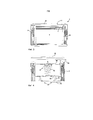
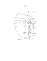
На Фиг. 1 и 2 проиллюстрировано выдачное устройство 2 согласно вариантам осуществления. Выдачное устройство 2 предусмотрено с резервуаром 6 для стопки листов листового материала. Выдачное устройство 2 содержит корпус 4. Выдачное устройство 2 содержит крышку 10, предусмотренную с выдачным отверстием 12 для листов листового материала. Крышка 10 обращена вверх во время использования выдачного устройства 2. Соответственно, сторона выдачного устройства 2, противоположная крышке 10, выполнена с возможностью образования опорной стороны выдачного устройства 2, причем эта опорная сторона расположена так, чтобы быть обращенной к поддерживающей поверхности, на которую ставится выдачное устройство 2. Опорная сторона выдачного устройства 2 может быть предусмотрена с одним или более элементами трения, такими как резиновые ножки или лапки других типов. Элемент трения может содержать липкий эластомерный состав, выполненный с возможностью отпускаемого и многократного прикрепления выдачного устройства 2 к поддерживающей поверхности. Соответственно, выдачное устройство 2 образует автономное устройство. Выдачное устройство 2 содержит кассету 16. Кассета 16 содержит резервуар 6 для стопки листов листового материала. Кассета 16 может перемещаться в корпусе 4. Кассета 16 выполнена с возможностью перемещения в положение по меньшей мере частично снаружи корпуса 4.In FIG. 1 and 2, dispensing
На Фиг. 1 выдачное устройство 2 показано с кассетой 16, расположенной внутри корпуса 4. На Фиг. 2 выдачное устройство 2 показано с кассетой 16 в верхнем конечном положении, причем в этом верхнем конечном положении кассета 16 находится частично снаружи корпуса 4. Кассета 16 может быть расположена в корпусе 4 таким образом, чтобы кассета 16 не могла быть вынута из корпуса 4 без разборки корпуса 4. В верхнем конечном положении, кассета 16 может быть повторно заполнена листами листового материала.In FIG. 1, the
Кассета 16 предусмотрена с отверстием 18 повторного заполнения для листов листового материала. Отверстие 18 повторного заполнения является доступным, когда кассета 16 находится в положении по меньшей мере частично снаружи корпуса 4. Таким образом, пользователь легко может повторно заполнять выдачное устройство 2 листами листового материала через отверстие 18 повторного заполнения, когда кассета находится в положении по меньшей мере частично снаружи корпуса.A
Крышка 10 прикреплена к кассете 16 или образует ее часть. Выдачное отверстие 12 и отверстие 18 повторного заполнения обращены, по существу, в перпендикулярных направлениях. То есть, выдачное отверстие 12 обращено вверх, а отверстие 18 повторного заполнения обращено вбок, когда выдачное устройство 2 поставлено на поддерживающую поверхность. Когда кассета 16 распложена в положении по меньшей мере частично снаружи корпуса 4, отверстие 18 повторного заполнения является доступным для повторного заполнения резервуара 6 листами листового материала. Стопка листов листового материала легко помещается в резервуар 6. Отверстие 18 повторного заполнения проходит по существу по всей длине кассеты 16 и по существу по всей ширине кассеты 16.The
Крышка 10, или часть у верхнего конца кассеты 16, образует верхнее ограничение резервуара 6. Таким образом, когда выдачное устройство 2 повторно заполняется листами листового материала, посредством этого ограничения предотвращается переполнение выдачного устройства 2. Таким образом, может быть обеспечена надежная выдача листов листового материала из заново наполненного выдачного устройства 2.The
Наоборот, выдачное устройство предшествующего уровня техники, которое повторно заполняется через верхнее отверстие под крышкой, предусмотренной с выдачным отверстием, может иметь риск переполнения. Из-за этого крышка должна прижиматься к корпусу. В этом типе предшествующего уровня техники выдача первых листов из переполненного выдачного устройства может быть затруднена.Conversely, a prior art dispensing device that is refilled through an upper opening under a cover provided with a dispensing opening may be at risk of overflow. Because of this, the cover must be pressed against the body. In this type of prior art, the delivery of first sheets from a crowded dispensing device may be difficult.
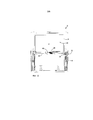
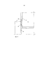
На Фиг. 3-5 показаны поперечные разрезы выдачного устройства 2, проиллюстрированного на Фиг. 1 и 2. На Фиг. 3 выдачное устройство 2 показано с кассетой 16 в нижнем концевом положении в корпусе 4. Кассета 16 закреплена в корпусе в этом нижнем концевом положении. В резервуаре 6 выдачного устройства 2 расположена стопка 8 листов листового материала. Листы листового материала могут быть выданы через выдачное отверстие 12 в крышке 10.In FIG. 3-5 show cross sections of the
На Фиг. 4 выдачное устройство 2 проиллюстрировано с частью кассеты 16, находящейся снаружи корпуса 4. Резервуар 6 выдачного устройства 2 является пустым и, таким образом, требует повторного заполнения.In FIG. 4, the
Выдачное устройство 2 содержит первое поджимающее устройство 14 для поджимания стопки листов листового материала в резервуаре 6 к крышке 10 и выдачному отверстию 12. Первое поджимающее устройство 14 расположено в кассете 16 и содержит подвижную платформу 60 для поддерживания стопки листов листового материала и первый упругий элемент 62, упирающийся в подвижную платформу 60 со стороны, противоположной стопке листов листового материала. В этих вариантах осуществления первый упругий элемент 62 содержит пружину, расположенную между нижним элементом 63 кассеты 16 и подвижной платформой 60. Поскольку резервуар 6 является пустым, платформа 60 поджимается в положение у верхнего конца корпуса 4.The
Только в качестве примера; резервуар 6 может вмещать стопку листов листового материала, имеющую высоту 10-20 см, или приблизительно 15 см. Листы листового материала могут иметь ширину 10-30 см, или приблизительно 24 см и размах 6-15 см, или приблизительно 9 см, в сложенном состоянии, в котором они находятся в выдачном устройстве 2. Первое поджимающее устройство 14 может обеспечивать поджимающую силу 10-12 Н, когда первое поджимающее устройство 14 полностью сжато, то есть, когда платформа 60 находится в нижнем положении в кассете 16.By way of example only;
Выдачное устройство 2 содержит второе поджимающее устройство 20, выполненное с возможностью поджимания кассеты 16 в вертикальном направлении к положению по меньшей мере частично снаружи корпуса 4. Как показано на Фиг. 4, второе поджимающее устройство 20 переместило часть кассеты 16 наружу корпуса 4. Кассета 16 может быть перемещена вручную дальше наружу корпуса 4 из положения, показанного на Фиг. 4, в верхнее конечное положение. Благодаря второму поджимающему устройству 20, кассета 16 частично выбрасывается из корпуса 4 при отпускании крепежного устройства 22, которое подробно описано ниже. Второе поджимающее устройство 20 содержит второй упругий элемент 73, расположенный между корпусом 4 и кассетой 16 у концевой части 74 корпуса 4 напротив крышки 10. Более конкретно, второй упругий элемент 73 может содержать пружину. В этих вариантах осуществления второе поджимающее устройство 20 содержит две пружины. Только в качестве примера; второе поджимающее устройство 20 может обеспечивать поджимающую силу приблизительно 15 Н, когда второе поджимающее устройство 20 полностью сжато, то есть, когда кассета 16 находится в нижнем положении в корпусе 4, как показано на Фиг. 3.The
На Фиг. 5 выдачное устройство 2 показано с кассетой 16 в верхнем конечном положении. В верхнем конечном положении резервуар 6 может быт повторно заполнен листами листового материала. Кассета 16 может удерживаться в положении по меньшей мере частично снаружи корпуса 4 посредством крепежного устройства 22, которое более подробно описано далее.In FIG. 5,
Платформа 60 находится в положении у верхнего конца корпуса 4. В верхнем конечном положении кассеты 16, подвижная платформа 60 и нижний элемент 63 кассеты 16 находятся вблизи друг от друга. Первый упругий элемент 62 сжат. Таким образом, все отверстие 18 повторного заполнения в кассете 16 доступно пользователю, который собирается повторно заполнить выдачное устройство 2.The
На Фиг. 6 проиллюстрированы варианты осуществления крепежного устройства 22 выдачного устройства 2, проиллюстрированного на Фиг. 1-5. Крепежное устройство 22 выполнено с возможностью удерживания кассеты 16 на месте в корпусе 4 против действия поджимающей силы второго поджимающего устройства 20. Соответствующее крепежное устройство предусмотрено у противоположной стороны выдачного устройства 2.In FIG. 6 illustrates embodiments of the
Крепежное устройство 22 выполнено с возможностью отпускания для обеспечения перемещения кассеты 16 к положению по меньшей мере частично снаружи корпуса 4. Когда крепежное устройство отпускается, кассета 16 частично выбрасывается из корпуса 4 посредством второго поджимающего устройства 20 в положение, показанное на Фиг. 4. Из этого положения пользователь может переместить кассету 16 в верхнее конечное положение кассеты 16, показанное на Фиг. 5.The
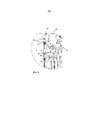
Крепежное устройство 22 в основном расположено в корпусе 4 и содержит выступающий элемент 30, соединительный элемент 46, третье поджимающее устройство 44, и нажимную кнопку 40. Крышка 10 предусмотрена со сквозным отверстием. Нажимная кнопка 40 доступна через крышку 10. Более конкретно, нажимная кнопка 40 доступна через сквозное отверстие крышки 10. Крышка 10 соединена с кассетой 16 и, таким образом, может перемещаться с кассетой 16. Соединительный элемент 46 выполнен с возможностью вращения вокруг оси 47 и содержит первый выступ 48 и второй выступ 49. Первый выступ 48 зацеплен с выступающим элементом 30. Более конкретно, первый выступ 48 проходит в окно 50 выступающего элемента 30. Нажимная кнопка 40 упирается во второй выступ 49. Третье поджимающее устройство 44 содержит торсионную пружину, намотанную вокруг оси 47. Торсионная пружина упирается с одного конца в соединительный элемент 46 и с противоположного конца в нажимную кнопку 40. Таким образом, третье поджимающее устройство 44 поджимает нажимную кнопку 40 к гнезду 52 в корпусе 4 и выступающий элемент 30, через первый выступ 48, к кассете 16. Таким образом, нажимная кнопка 40 поджимается в направлении наружу от выдачного устройства 2 к наружному положению. Из наружного положения нажимная кнопка 40 может быть приведена в действие пользователем, желающим получить доступ в резервуар 6.The fixing
Выступающий элемент 30 выполнен с возможностью выступания в выемку 32, предусмотренную в кассете 16. Таким образом, выступающий элемент 30 зацепляется с кассетой 16 в выемке 32 и удерживает кассету 16 на месте в корпусе 4, против действия поджимающей силы второго поджимающего устройства 20. Поскольку выступающий элемент 30 поджимается в направлении к кассете 16, обеспечивается зацепление выступающего элемента 30 с кассетой 16 и выемкой 32 в ней.The protruding
Более того, крепежное устройство 22 выполнено с возможностью удерживания кассеты 16 в положении по меньшей мере частично снаружи корпуса 4. Это достигается посредством выступающего элемента 30, проходящего под кассетой 16, когда кассета 16 находится в своем верхнем конечном положении, как показано на Фиг. 5. Опять же, поджимание выступающего элемента 30 к кассете 16 обеспечивает то, что выступающий элемент 30 будет расположен под кассетой 16. Выступающий элемент 30 содержит наклонный край 34, выполненный с возможностью упирания в наружную поверхность кассеты 16. Таким образом, нижняя часть кассеты 16, опирающаяся на наклонный край 34 выступающего элемента 30, может отжимать выступающий элемент 30, против действия третьего поджимающего устройства 44, в направлении от кассеты 16, когда на крышку 10 выдачного устройства 2 прилагается направленное вниз давление. Когда, при повторном помещении кассеты 16 в корпус 4, кассета 16 достигает положения, проиллюстрированного на Фиг. 4, пользователь может нажать на крышку 10 для возвращения кассеты 16 в нижнее концевое положение в корпусе 4, причем в этом нижнем концевом положении третье поджимающее устройство 44 поджимает выступающий элемент 30 в выемку 32 в кассете 16.Moreover, the mounting
Когда кассета 16 находится в своем нижнем концевом положении, как показано на Фиг. 3, и поскольку нажимная кнопка 40 соединена с выступающим элементом 30 через соединительный элемент 46 и его первый и второй выступы 48, 49, приведение в действие нажимной кнопки 40 отпускает выступающий элемент 30 от выемки 32, и кассета 16 выбрасывается посредством второго поджимающего устройства 20 в положение, проиллюстрированное на Фиг. 4. Приведение в действие нажимной кнопки 40 в этих вариантах осуществления содержит нажатие нажимной кнопки 40 вниз.When the
Когда кассета 16 находится в своем верхнем конечном положении, как показано на Фиг. 4, приведение в действие нажимной кнопки 40 приводит к отпусканию крепежного устройства 22, так чтобы кассета 16 могла быть перемещена вниз в положение, проиллюстрированное на Фиг. 4. Из этого положения, пользователь может нажать на крышку 10 для возврата кассеты 16 в нижнее концевое положение, как показано на Фиг. 3.When the
В качестве альтернативы, когда кассета 16 находится в своем верхнем конечном положении, как показано на Фиг. 4, пользователь может нажать на крышку 10, посредством чего крепежное устройство 22 отпускается, и кассета 16 может быть перемещена вниз в положение, проиллюстрированное на Фиг. 4. Из этого положения, пользователь может продолжить нажимать на крышку 10, чтобы вернуть кассету 16 в нижнее концевое положение, как показано на Фиг. 3.Alternatively, when the
На Фиг. 7a и 7b показана внутренняя часть выдачного устройства 2, проиллюстрированного на Фиг. 1-6. На Фиг. 7a и 7b показан индикатор 70 уровня для показывания уровня листов листового материала в резервуаре 6. Индикатор 70 уровня выполнен с возможностью перемещения в вертикальном направлении, как видно, когда выдачное устройство 2 поставлено на поверхность, и его крышка 10 обращена вверх. Индикатор 70 уровня виден снаружи выдачного устройства 2 через смотровое отверстие 72. Поверхность 74 индикатора 70 уровня, обращенная к смотровому отверстию 72 имеет разные цвета в ее верхней и нижней частях. Например, верхняя часть поверхности 74 может быть окрашена в зеленый цвет, а нижняя часть поверхности 74 может быть окрашена в красный цвет. Таким образом, зеленый цвет виден через смотровое отверстие 72, когда индикатор 70 уровня находится в нижнем положении, как показано на Фиг. 7a, а красный цвет виден через смотровое отверстие 72, когда индикатор 70 уровня находится в верхнем положении, как показано на Фиг. 7b.In FIG. 7a and 7b show the inside of the
Подвижная платформа 60 в кассете 16 зацепляется с индикатором 70 уровня, когда подвижная платформа 60 достигает концевой части корпуса 4 рядом с крышкой 10, и смещает индикатор 70 уровня из первого положения по меньшей мере во второе положение, например, из нижнего положения в положение ближе к верхнему положению.The
В своем нижнем положении, индикатор 70 уровня опирается а планку 76, расположенную на внутренней стороне корпуса 4. Подвижная платформа 60 предусмотрена с протуберанцем 78. Протуберанец 78 зацепляется с индикатором 70 уровня, когда подвижная платформа 60 перемещается к крышке 10 посредством первого поджимающего устройства 14, по мере уменьшения стопки листов листового материала в резервуаре 6.In its lower position, the
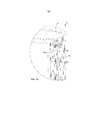
На Фиг. 8 проиллюстрирован частичный поперечный разрез выдачного устройства 2 согласно вариантам осуществления. Выдачное устройство 2 может содержать признаки, описанные в вариантах осуществления, показанных на Фиг. 1-7b. Кассета 16 выдачного устройства 2 содержит выступ 80 на наружной части кассеты 16, и корпус 4 выдачного устройства 2 предусмотрен с канавкой 82. Выступ 80 выполнен с возможностью скольжения в канавке 82 и вдоль канавки 82, когда кассета 16 перемещается вдоль корпуса 4. Таким образом, кассета 16 направляется посредством выступа 80, скользящего вдоль канавки 82. Выступ 80 является упругим и зацепляется с трением с корпусом 4 в канавке 82.In FIG. 8 is a partial cross-sectional view of a
Корпус 4 содержит протуберанец 84, расположенный в канавке 82 так, чтобы выступ 80 мог зацепляться с возможностью отпускания с протуберанцем 84, когда выступ 80 задвигается за протуберанец 84 в канавке 82. Таким образом, кассета 16 может удерживаться в конкретном положении в корпусе 4 посредством зацепления между протуберанцем 84 и выступом 80. Например, зацепление между протуберанцем 84 и выступом 80 может удерживать кассету 16 в положении по меньшей мере частично снаружи корпуса 4 для повторного заполнения резервуара 6 в кассете 16 листами листового материала, как показано на Фиг. 8. Выдачное устройство 2 может дополнительно содержать крепежное устройство 22, как описано со ссылкой на Фиг. 6.The
На Фиг. 9 проиллюстрированы варианты осуществления способа повторного заполнения выдачного устройства стопкой листов листового материала. Выдачное устройство может представлять собой выдачное устройство 2, описанное в этом документе. Соответственно, способ дополнительно проиллюстрирован, например, на Фиг. 3–5, на которых описаны разные положения кассеты 16 в корпусе 4 выдачного устройства 2. Выдачное устройство предусмотрено с резервуаром для стопки листов листового материала и содержит корпус. Выдачное устройство содержит крышку, предусмотренную с выдачным отверстием для листов листового материала, причем крышка выполнена с возможностью быть обращенной вверх во время использования выдачного устройства. Выдачное устройство содержит первое поджимающее устройство для поджимания стопки листов листового материала к крышке и выдачному отверстию. Кассета содержит резервуар и выполнена с возможностью перемещения в положение по меньшей мере частично снаружи корпуса, причем кассета предусмотрена с отверстием повторного заполнения для листов листового материала, причем отверстие повторного заполнения является доступным, когда кассета находится в положении по меньшей мере частично снаружи корпуса. Крышка, или часть у верхнего конца кассеты, образует верхнее ограничение резервуара. Способ содержит:In FIG. 9 illustrates embodiments of a method for refilling a dispenser with a stack of sheets of sheet material. The dispensing device may be a dispensing
- перемещение 100 кассеты вверх в положение по меньшей мере частично снаружи корпуса, и- moving the cassette 100 up to a position at least partially outside the housing, and
- повторное заполнение 102 резервуара листами листового материала посредством помещения стопки листов листового материала через отверстие повторного заполнения в резервуар внутри образованного верхнего ограничения.- refilling the reservoir 102 with sheets of sheet material by placing a stack of sheets of sheet material through the refill hole in the reservoir within the upper limit formed.
Согласно вариантам осуществления, выдачное устройство может содержать второе поджимающее устройство, выполненное с возможностью поджимания кассеты в вертикальном направлении к положению по меньшей мере частично снаружи корпуса. Перемещение 100 может содержать:According to embodiments, the dispensing device may comprise a second pressing device configured to press the cartridge in a vertical direction to a position at least partially outside the housing. Moving 100 may contain:
- выбрасывание 104 кассеты из корпуса посредством второго поджимающего устройства к положению по меньшей мере частично снаружи корпуса. Таким образом, частичное перемещение к положению по меньшей мере частично снаружи корпуса может быть достигнуто посредством второго поджимающего устройства. Полное перемещение к положению по меньшей мере частично снаружи корпуса, в котором выдачное устройство может быть повторно заполнено, может быть достигнуто посредством пользователя, перемещающего кассету из выброшенного положения в положение по меньшей мере частично снаружи корпуса.ejecting the cassette 104 from the housing by means of a second pressing device to a position at least partially outside the housing. Thus, partial movement to a position at least partially outside the housing can be achieved by a second pressing device. Full movement to a position at least partially outside the housing, in which the dispensing device can be refilled, can be achieved by a user moving the cartridge from the ejected position to the position at least partially outside the housing.
Согласно вариантам осуществления, выдачное устройство может содержать крепежное устройство для удерживания кассеты на месте в корпусе против действия поджимающей силы второго поджимающего устройства. Перемещение 100 может содержать:According to embodiments, the dispensing device may include a fastening device for holding the cartridge in place in the housing against the action of the pressing force of the second pressing device. Moving 100 may contain:
- отпускание 106 крепежного устройства для обеспечения перемещения кассеты к положению по меньшей мере частично снаружи корпуса. Таким образом, кассета может не выбрасываться из корпуса посредством второго поджимающего устройства к положению по меньшей мере частично снаружи корпуса до тех пор, пока не произойдет отпускание 106 крепежного устройства.- releasing 106 of the mounting device to allow the cartridge to move to a position at least partially outside the housing. Thus, the cartridge may not be ejected from the housing by means of the second pressing device to a position at least partially outside the housing until the fastening device 106 is released.
Согласно вариантам осуществления, крепежное устройство 22 может содержать нажимную кнопку 40, и перемещение 100 может содержать приведение в действие нажимной кнопки 40 для отпускания крепежного устройства 22.According to embodiments, the
Согласно вариантам осуществления, способ может содержать:According to embodiments, the method may comprise:
- повторное помещение 108 кассеты в корпус. Таким образом, кассета может быть возвращена в корпус после повторного заполнения резервуара стопкой листов листового материала, и листы листового материала могут быть выданы из выдачного устройства через его выдачное отверстие.- re-placing 108 cassettes in the housing. Thus, the cartridge can be returned to the housing after refilling the reservoir with a stack of sheets of sheet material, and sheets of sheet material can be discharged from the dispensing device through its dispensing opening.
Согласно вариантам осуществления, выдачное устройство может содержать крепежное устройство 22 для удерживания кассеты на месте в положении по меньшей мере частично снаружи корпуса, и повторное помещение 108 может содержать отпускание крепежного устройства 22 для обеспечения перемещения кассеты к положению в корпусе.According to embodiments, the dispenser may include a
Согласно вариантам осуществления, крепежное устройство 22 может содержать нажимную кнопку, и повторное помещение содержать приведение в действие нажимной кнопки 40 для отпускания крепежного устройства 22.According to embodiments, the
Согласно альтернативным вариантам осуществления, повторное помещение 108 может содержать толкание кассеты к корпусу для отпускания крепежного устройства 22 для обеспечения перемещения кассеты к положению в корпусе.According to alternative embodiments, re-placement 108 may comprise pushing the cartridge to the housing to release the mounting
Согласно вариантам осуществления, повторное заполнение 102 может содержать:According to embodiments, refill 102 may comprise:
- помещение 110 стопки, имеющей высоту 10-20 см, в резервуар.- placing 110 stacks having a height of 10-20 cm in the tank.
Специалисту в данной области техники будет понятно, что описанные выше иллюстративные варианты осуществления могут быть объединены. Корпус 4 может содержать два боковых элемента, которые прикреплены друг к другу, и нижнюю часть, прикрепленную к боковым элементам, например, посредством винтов. Корпус 4 может содержать облицовку из листового металла. Облицовка из листового металла может проходить вокруг наружных сторон двух боковых элементов. Облицовка из листового металла может быть прикреплена к боковым элементам, например, посредством клея или двухсторонней клейкой ленты. У смотрового отверстия 72, облицовка из листового металла может быть предусмотрена с щелью для обнажения смотрового отверстия 72. Несмотря на то, что изобретение описано со ссылкой на иллюстративные варианты осуществления, специалистам в данной области техники будет понятно множество различных изменений, модификаций и тому подобного. Таким образом, следует понимать, что изложенное выше является иллюстрацией различных иллюстративных вариантов осуществления, и что изобретение определено только прилагаемой формулой изобретения.One skilled in the art will understand that the above illustrative embodiments may be combined. The
В контексте настоящего документа, термин "содержащий" или "содержит" не является ограничивающим и включает в себя один или более изложенных признаков, элементов, этапов, компонентов или функций, но не исключает присутствия или добавления одного или более других признаков, элементов, этапов, компонентов, функций или их групп.In the context of this document, the term "comprising" or "contains" is not limiting and includes one or more of the described features, elements, steps, components or functions, but does not exclude the presence or addition of one or more other features, elements, steps, components, functions or their groups.
Claims (31)
Applications Claiming Priority (1)
| Application Number | Priority Date | Filing Date | Title |
|---|---|---|---|
| PCT/SE2013/050558 WO2014185842A1 (en) | 2013-05-17 | 2013-05-17 | Dispenser and method of refilling dispenser |
Publications (2)
| Publication Number | Publication Date |
|---|---|
| RU2015153826A RU2015153826A (en) | 2017-06-22 |
| RU2625730C2 true RU2625730C2 (en) | 2017-07-18 |
Family
ID=51898686
Family Applications (1)
| Application Number | Title | Priority Date | Filing Date |
|---|---|---|---|
| RU2015153826A RU2625730C2 (en) | 2013-05-17 | 2013-05-17 | Dispensing device and method of repeated filling of the dispensing device |
Country Status (12)
| Country | Link |
|---|---|
| US (3) | US20160088982A1 (en) |
| EP (1) | EP2996530B1 (en) |
| CN (1) | CN105208904B (en) |
| AU (1) | AU2013389392B2 (en) |
| BR (1) | BR112015028872A2 (en) |
| CA (1) | CA2912370A1 (en) |
| DK (1) | DK2996530T3 (en) |
| ES (1) | ES2729577T3 (en) |
| MX (1) | MX364921B (en) |
| PL (1) | PL2996530T3 (en) |
| RU (1) | RU2625730C2 (en) |
| WO (1) | WO2014185842A1 (en) |
Families Citing this family (13)
| Publication number | Priority date | Publication date | Assignee | Title |
|---|---|---|---|---|
| FR2907654B1 (en) | 2006-10-31 | 2010-01-29 | Georgia Pacific France | PROCESS, MANUFACTURING DEVICE AND ASSOCIATED ROLLS FORMED OF CUTTING SHEETS AND ALTERNATE PREDECOUPLES |
| US11297984B2 (en) | 2006-10-31 | 2022-04-12 | Gpcp Ip Holdings Llc | Automatic napkin dispenser |
| US10383489B2 (en) * | 2012-02-10 | 2019-08-20 | Gpcp Ip Holdings Llc | Automatic napkin dispenser |
| US9604811B2 (en) | 2013-10-01 | 2017-03-28 | Georgia-Pacific Consumer Products Lp | Automatic paper product dispenser with data collection and method |
| AU2013407360B2 (en) * | 2013-12-09 | 2016-12-15 | Essity Hygiene And Health Aktiebolag | Dispenser for interfolded napkins |
| CA3044547A1 (en) * | 2017-01-09 | 2018-07-12 | Essity Hygiene And Health Aktiebolag | Dispenser for dispensing sheet products |
| CN114947592A (en) | 2017-05-10 | 2022-08-30 | Gpcp知识产权控股有限责任公司 | Automated paper product dispenser and associated method |
| ES2974206T3 (en) * | 2019-10-15 | 2024-06-26 | Sofidel Spa | Dispenser for leaf-shaped cellulose products |
| US10980377B1 (en) * | 2019-12-18 | 2021-04-20 | Essity Hygiene And Health Aktiebolag | Apparatus and methods for paper dispensing |
| US11116365B2 (en) | 2019-12-18 | 2021-09-14 | Essity Hygiene And Health Aktiebolag | Horizontally oriented paper product dispenser and related methods |
| US11641986B2 (en) * | 2020-12-01 | 2023-05-09 | Cintas Corporate Services, Inc. | Multi-orientation towel dispenser |
| US20230320470A1 (en) * | 2022-04-12 | 2023-10-12 | Jeff King Hair, LLC | Holder and Dispenser for Folded Hair Treatment Materials |
| USD1025645S1 (en) * | 2023-04-05 | 2024-05-07 | Stephanie Todd | Liner dispenser |
Citations (5)
| Publication number | Priority date | Publication date | Assignee | Title |
|---|---|---|---|---|
| US3106314A (en) * | 1961-12-20 | 1963-10-08 | Rufus P Spears | Advertising napkin holder |
| US20020030045A1 (en) * | 1999-09-14 | 2002-03-14 | Keiichi Nakamura | Wet tissue warmer and tissue lifting plate |
| US20060273102A1 (en) * | 2005-06-03 | 2006-12-07 | Russell Wieser | Table top folded sheet dispenser |
| US20070034638A1 (en) * | 2004-05-07 | 2007-02-15 | Sca Hygiene Products Ab | Apparatus for serially dispensing folder sheet products |
| RU2006143216A (en) * | 2004-05-07 | 2008-06-20 | Ска Хайджин Продактс Аб (Se) | ISSUING DEVICE FOR SEPARATE FOLDED CANVAS |
Family Cites Families (35)
| Publication number | Priority date | Publication date | Assignee | Title |
|---|---|---|---|---|
| US2277815A (en) * | 1939-07-05 | 1942-03-31 | Marathon Paper Mills Co | Dispenser |
| US2435104A (en) * | 1946-01-09 | 1948-01-27 | Joseph H Solomon | Napkin holder |
| NL73002C (en) * | 1948-10-28 | |||
| US3214227A (en) * | 1964-07-09 | 1965-10-26 | American Can Co | Dispenser |
| US3343716A (en) * | 1966-03-22 | 1967-09-26 | Peebles David Meade | Dispensers for facial tissues and the like |
| US3826406A (en) * | 1970-05-25 | 1974-07-30 | V Moniot | Article dispenser |
| CA1098874A (en) * | 1980-02-07 | 1981-04-07 | Frank Richardson | Serviette dispenser |
| NL8102986A (en) * | 1981-06-19 | 1983-01-17 | Avedko Bv | DEVICE FOR STACKING OBJECTS. |
| US4694973A (en) * | 1985-12-02 | 1987-09-22 | Warmwipes, Inc. | Warming device for disposable towel dispenser |
| US4838454A (en) * | 1987-11-02 | 1989-06-13 | Traex Corporation | Napkin dispenser |
| USD361432S (en) * | 1993-11-12 | 1995-08-22 | Giovanni Lotti | Container, dispenser for ear cleaning sticks |
| US5678728A (en) * | 1995-06-22 | 1997-10-21 | Leto; Maria | Dispenser for flexible sheets |
| US6062421A (en) * | 1998-01-23 | 2000-05-16 | Marley; Jo Ellen | Glove dispensing device |
| AU136029S (en) * | 1998-04-09 | 1998-12-15 | Mt Cup Corp Pty Ltd | A box |
| US20020162849A1 (en) | 2001-05-04 | 2002-11-07 | Chen Fang Yeh | Structure art design knife blade container |
| GB0124867D0 (en) * | 2001-10-17 | 2001-12-05 | Ncr Int Inc | Media cassette |
| US7093737B2 (en) | 2003-04-16 | 2006-08-22 | Kimberly-Clark Worldwide, Inc. | Container and cartridge for dispensing paper products |
| US7048143B2 (en) * | 2003-04-16 | 2006-05-23 | Kimberly-Clark Worldwide, Inc. | Container and cartridge for dispensing paper products |
| USD482915S1 (en) * | 2003-06-02 | 2003-12-02 | Simplehuman Llc | Plastic bag dispenser |
| US6981610B2 (en) * | 2004-03-10 | 2006-01-03 | Traex Company | Dispenser for a paper product |
| US7490733B2 (en) * | 2005-01-19 | 2009-02-17 | Daria Tagliareni | Dispenser assembly |
| US7726515B2 (en) * | 2005-04-29 | 2010-06-01 | Kimberly-Clark Worldwide, Inc. | Decorative and disposable bath tissue dispenser |
| USD524084S1 (en) | 2005-06-03 | 2006-07-04 | Sca Hygiene Products Ab | Table top dispenser for folded absorbent sheet products |
| US20060273101A1 (en) * | 2005-06-07 | 2006-12-07 | Kimberly-Clark Worldwide, Inc. | Container and cartridge for dispensing paper products |
| US20070181594A1 (en) * | 2005-11-23 | 2007-08-09 | Thompson Mark C | Wall dispenser for rolled toilet paper and moistened wipes |
| AU2007335183B2 (en) * | 2006-12-19 | 2014-02-13 | Eduard Haas | Refillable single-hand dispenser for tablets |
| US20090191518A1 (en) * | 2008-01-28 | 2009-07-30 | Jill Rappa | Educational device and system therefore |
| US20130164729A1 (en) * | 2008-01-28 | 2013-06-27 | Jill S. Rappa | Educational device and kit therefore |
| US8631968B2 (en) * | 2011-06-04 | 2014-01-21 | Tony A. Taylor | Tissue advancement device for tissue boxes |
| US8863984B2 (en) * | 2011-08-30 | 2014-10-21 | Sca Hygiene Products Ab | Product dispenser and cover member for a product dispenser |
| CN202505244U (en) * | 2012-02-14 | 2012-10-31 | 陈剑峰 | Paper towel box with paper towel board capable of being automatically supported |
| CN202859006U (en) * | 2012-08-21 | 2013-04-10 | 李修志 | Convenience paper sheet pulling carton |
| US9125532B2 (en) * | 2012-12-20 | 2015-09-08 | Kimberly-Clark Worldwide, Inc. | Storing and dispensing container for wipes |
| US9230388B2 (en) * | 2013-03-14 | 2016-01-05 | Nice-Pak Products, Inc. | Flow wrap holder |
| WO2017023648A1 (en) * | 2015-08-05 | 2017-02-09 | Wausau Paper Towel & Tissue, Llc | Interfolded sheet dispenser |
-
2013
- 2013-05-17 BR BR112015028872A patent/BR112015028872A2/en not_active IP Right Cessation
- 2013-05-17 EP EP13884430.3A patent/EP2996530B1/en not_active Not-in-force
- 2013-05-17 PL PL13884430T patent/PL2996530T3/en unknown
- 2013-05-17 AU AU2013389392A patent/AU2013389392B2/en not_active Ceased
- 2013-05-17 MX MX2015015557A patent/MX364921B/en active IP Right Grant
- 2013-05-17 DK DK13884430.3T patent/DK2996530T3/en active
- 2013-05-17 RU RU2015153826A patent/RU2625730C2/en not_active IP Right Cessation
- 2013-05-17 CA CA2912370A patent/CA2912370A1/en not_active Abandoned
- 2013-05-17 ES ES13884430T patent/ES2729577T3/en active Active
- 2013-05-17 US US14/891,367 patent/US20160088982A1/en not_active Abandoned
- 2013-05-17 WO PCT/SE2013/050558 patent/WO2014185842A1/en not_active Ceased
- 2013-05-17 CN CN201380076550.5A patent/CN105208904B/en not_active Expired - Fee Related
-
2018
- 2018-12-04 US US29/672,270 patent/USD903365S1/en active Active
- 2018-12-04 US US29/672,272 patent/USD903366S1/en active Active
Patent Citations (5)
| Publication number | Priority date | Publication date | Assignee | Title |
|---|---|---|---|---|
| US3106314A (en) * | 1961-12-20 | 1963-10-08 | Rufus P Spears | Advertising napkin holder |
| US20020030045A1 (en) * | 1999-09-14 | 2002-03-14 | Keiichi Nakamura | Wet tissue warmer and tissue lifting plate |
| US20070034638A1 (en) * | 2004-05-07 | 2007-02-15 | Sca Hygiene Products Ab | Apparatus for serially dispensing folder sheet products |
| RU2006143216A (en) * | 2004-05-07 | 2008-06-20 | Ска Хайджин Продактс Аб (Se) | ISSUING DEVICE FOR SEPARATE FOLDED CANVAS |
| US20060273102A1 (en) * | 2005-06-03 | 2006-12-07 | Russell Wieser | Table top folded sheet dispenser |
Also Published As
| Publication number | Publication date |
|---|---|
| WO2014185842A1 (en) | 2014-11-20 |
| EP2996530A1 (en) | 2016-03-23 |
| PL2996530T3 (en) | 2019-08-30 |
| USD903366S1 (en) | 2020-12-01 |
| BR112015028872A2 (en) | 2017-07-25 |
| AU2013389392A1 (en) | 2015-11-26 |
| CN105208904B (en) | 2018-09-14 |
| DK2996530T3 (en) | 2019-06-11 |
| EP2996530A4 (en) | 2017-01-18 |
| EP2996530B1 (en) | 2019-05-08 |
| CN105208904A (en) | 2015-12-30 |
| USD903365S1 (en) | 2020-12-01 |
| RU2015153826A (en) | 2017-06-22 |
| US20160088982A1 (en) | 2016-03-31 |
| MX2015015557A (en) | 2016-02-05 |
| CA2912370A1 (en) | 2014-11-20 |
| AU2013389392B2 (en) | 2016-03-03 |
| ES2729577T3 (en) | 2019-11-04 |
| MX364921B (en) | 2019-05-14 |
Similar Documents
| Publication | Publication Date | Title |
|---|---|---|
| RU2625730C2 (en) | Dispensing device and method of repeated filling of the dispensing device | |
| EP2850985B1 (en) | Tabletop napkin dispenser | |
| EP2386855B1 (en) | Hermetically sealed test strip container | |
| US9918598B2 (en) | Side-by-side tissue dispenser door restriction mechanism | |
| CN100408456C (en) | Meter Strip Dispenser Assembly | |
| US10064525B2 (en) | Dispenser of towels wetted with hand sanitizer | |
| US6508380B1 (en) | Dispenser for the dispensing elements in strips | |
| CN108697281B (en) | Dispensing system | |
| RU2572170C2 (en) | Device for delivery of bent sheet products fitted with overfill prevention device | |
| CA2610344A1 (en) | Table top folded sheet dispenser | |
| KR101369088B1 (en) | Tape dispenser | |
| WO2018192636A1 (en) | Dispenser for dispensing sheet products | |
| KR20250124390A (en) | Soap dispenser with shield | |
| KR20250149667A (en) | Soap strip dispenser | |
| GB2454903A (en) | A sheets dispenser |
Legal Events
| Date | Code | Title | Description |
|---|---|---|---|
| PD4A | Correction of name of patent owner | ||
| MM4A | The patent is invalid due to non-payment of fees |
Effective date: 20200518 |