RU2657110C2 - Distributed piezoelectric power converter - Google Patents
Distributed piezoelectric power converter Download PDFInfo
- Publication number
- RU2657110C2 RU2657110C2 RU2016144001A RU2016144001A RU2657110C2 RU 2657110 C2 RU2657110 C2 RU 2657110C2 RU 2016144001 A RU2016144001 A RU 2016144001A RU 2016144001 A RU2016144001 A RU 2016144001A RU 2657110 C2 RU2657110 C2 RU 2657110C2
- Authority
- RU
- Russia
- Prior art keywords
- piezoelectric
- particle
- converter
- transducer
- optical
- Prior art date
Links
- 239000002245 particle Substances 0.000 claims abstract description 40
- 239000003990 capacitor Substances 0.000 claims abstract description 28
- 230000003287 optical effect Effects 0.000 claims abstract description 17
- 239000013307 optical fiber Substances 0.000 claims abstract description 17
- 230000005540 biological transmission Effects 0.000 claims abstract description 8
- 239000000835 fiber Substances 0.000 claims description 18
- 238000005259 measurement Methods 0.000 abstract description 11
- 238000013461 design Methods 0.000 abstract description 8
- 238000005065 mining Methods 0.000 abstract description 8
- 239000011435 rock Substances 0.000 abstract description 6
- 238000009434 installation Methods 0.000 abstract description 5
- 230000003245 working effect Effects 0.000 abstract description 4
- 230000009471 action Effects 0.000 abstract description 3
- 239000004020 conductor Substances 0.000 abstract description 3
- 230000000694 effects Effects 0.000 abstract description 3
- 230000009467 reduction Effects 0.000 abstract description 3
- 239000000126 substance Substances 0.000 abstract description 3
- 238000012546 transfer Methods 0.000 abstract description 3
- 238000003745 diagnosis Methods 0.000 abstract description 2
- 238000009826 distribution Methods 0.000 abstract description 2
- 238000005516 engineering process Methods 0.000 abstract description 2
- 238000012544 monitoring process Methods 0.000 abstract description 2
- 239000004243 E-number Substances 0.000 abstract 1
- 238000004140 cleaning Methods 0.000 abstract 1
- 230000004907 flux Effects 0.000 description 11
- 238000000034 method Methods 0.000 description 8
- 238000006243 chemical reaction Methods 0.000 description 7
- 230000008859 change Effects 0.000 description 5
- 230000005855 radiation Effects 0.000 description 5
- 238000004891 communication Methods 0.000 description 4
- 238000010586 diagram Methods 0.000 description 4
- 230000033001 locomotion Effects 0.000 description 4
- 230000008569 process Effects 0.000 description 4
- 238000005421 electrostatic potential Methods 0.000 description 3
- 238000004880 explosion Methods 0.000 description 3
- 238000004519 manufacturing process Methods 0.000 description 3
- 229910052751 metal Inorganic materials 0.000 description 3
- 239000002184 metal Substances 0.000 description 3
- 238000005555 metalworking Methods 0.000 description 3
- 239000012798 spherical particle Substances 0.000 description 3
- JRPBQTZRNDNNOP-UHFFFAOYSA-N barium titanate Chemical compound [Ba+2].[Ba+2].[O-][Ti]([O-])([O-])[O-] JRPBQTZRNDNNOP-UHFFFAOYSA-N 0.000 description 2
- 229910002113 barium titanate Inorganic materials 0.000 description 2
- 239000003245 coal Substances 0.000 description 2
- 230000006835 compression Effects 0.000 description 2
- 238000007906 compression Methods 0.000 description 2
- 229910052736 halogen Inorganic materials 0.000 description 2
- 150000002367 halogens Chemical class 0.000 description 2
- 230000036039 immunity Effects 0.000 description 2
- 230000007246 mechanism Effects 0.000 description 2
- 230000000704 physical effect Effects 0.000 description 2
- 238000012545 processing Methods 0.000 description 2
- 230000002123 temporal effect Effects 0.000 description 2
- VVQNEPGJFQJSBK-UHFFFAOYSA-N Methyl methacrylate Chemical compound COC(=O)C(C)=C VVQNEPGJFQJSBK-UHFFFAOYSA-N 0.000 description 1
- 229920005372 Plexiglas® Polymers 0.000 description 1
- 239000004793 Polystyrene Substances 0.000 description 1
- 230000003321 amplification Effects 0.000 description 1
- 230000000712 assembly Effects 0.000 description 1
- 238000000429 assembly Methods 0.000 description 1
- 244000309464 bull Species 0.000 description 1
- 239000000919 ceramic Substances 0.000 description 1
- 238000001514 detection method Methods 0.000 description 1
- 238000011161 development Methods 0.000 description 1
- 230000005684 electric field Effects 0.000 description 1
- 230000005686 electrostatic field Effects 0.000 description 1
- 239000012530 fluid Substances 0.000 description 1
- 239000012634 fragment Substances 0.000 description 1
- 231100001261 hazardous Toxicity 0.000 description 1
- 238000009413 insulation Methods 0.000 description 1
- 230000010354 integration Effects 0.000 description 1
- 239000007788 liquid Substances 0.000 description 1
- 230000004807 localization Effects 0.000 description 1
- 230000007774 longterm Effects 0.000 description 1
- 238000012423 maintenance Methods 0.000 description 1
- 238000011089 mechanical engineering Methods 0.000 description 1
- 238000003199 nucleic acid amplification method Methods 0.000 description 1
- 230000010355 oscillation Effects 0.000 description 1
- 230000003534 oscillatory effect Effects 0.000 description 1
- 230000010287 polarization Effects 0.000 description 1
- 229920002223 polystyrene Polymers 0.000 description 1
- 238000002360 preparation method Methods 0.000 description 1
- 238000007670 refining Methods 0.000 description 1
- 230000001105 regulatory effect Effects 0.000 description 1
- 238000007789 sealing Methods 0.000 description 1
- 230000008054 signal transmission Effects 0.000 description 1
- 238000003860 storage Methods 0.000 description 1
- 230000000007 visual effect Effects 0.000 description 1
Images
Classifications
-
- G—PHYSICS
- G01—MEASURING; TESTING
- G01L—MEASURING FORCE, STRESS, TORQUE, WORK, MECHANICAL POWER, MECHANICAL EFFICIENCY, OR FLUID PRESSURE
- G01L1/00—Measuring force or stress, in general
- G01L1/16—Measuring force or stress, in general using properties of piezoelectric devices
Landscapes
- Physics & Mathematics (AREA)
- General Physics & Mathematics (AREA)
- Arrangements For Transmission Of Measured Signals (AREA)
- Length Measuring Devices By Optical Means (AREA)
Abstract
Description
Изобретение относится к измерительной технике и может быть использовано в различных отраслях промышленности (горнодобывающей, нефтегазовой, машиностроения, химической и др.) для дистанционной индикации и регистрации механических усилий, в частности, для диагностики и мониторинга напряженно - деформированного состояния массива горных пород в окрестностях капитальных, очистных и подготовительных горных выработок, целиков, а также при техносферных и природных чрезвычайных ситуаций.The invention relates to measuring equipment and can be used in various industries (mining, oil and gas, mechanical engineering, chemical, etc.) for remote indication and registration of mechanical forces, in particular, for the diagnosis and monitoring of stress - strain state of a rock mass in the vicinity of capital , treatment and preparatory workings, pillars, as well as in technosphere and natural emergencies.
Известны различные устройства для индикации механических усилий, например, с помощью сложных пружинных (рычажных) или гидравлических преобразователей [1]. Устройства с механическим или гидравлическим преобразователем усилий сложны по конструкции, недостаточно надежны в работе из-за наличия трущихся между собой деталей и не позволяют передавать информацию дистанционно.There are various devices for indicating mechanical forces, for example, using complex spring (lever) or hydraulic converters [1]. Devices with a mechanical or hydraulic force converter are complex in design, insufficiently reliable due to the presence of parts rubbing together and do not allow information to be transmitted remotely.
Более современными и перспективными устройствами для преобразования механических усилий являются устройства, в основе которых лежит принцип преобразования механических напряжений в пьезоэлектрический сигнал [2]. Хотя устройства с пьезокристаллами просты по конструкции, но для дистанционной индикации сигналов с пьезоэлементов требуется специальная электронная усилительная и регистрирующая аппаратура.More modern and promising devices for converting mechanical forces are devices based on the principle of converting mechanical stresses into a piezoelectric signal [2]. Although devices with piezocrystals are simple in design, remote sensing of signals from piezoelectric elements requires special electronic amplification and recording equipment.
Кроме пьезопреобразователей, для измерении деформации широко используются тензометрические преобразователи, например, для слежения за изменениями горного давления в массиве пород, непосредственно при ведении горных работ и в режиме долгосрочных наблюдений используются датчики с тензометрической сборкой типа КФ5М-10-200-Н-12 (набор из четырех тензорезисторов). Данными датчиками совместно с высокоточной тензоаппаратурой проведена диагностика горных массивов угольного бассейна Кузбасса и разработаны методики безопасных работ [3]. Недостатком тензометрических измерений является наличие аналоговой электрической связи между датчиками и измерительной аппаратурой. Соединительную линию из электрических проводников необходимо прокладывать на большие расстояния от места установки датчика в массиве горной породы до пункта измерения находящегося на поверхности массива. При этом к линии соединения и датчикам предъявляются жесткие требования: необходимая изоляция от влаги, механическая прочность, помехозащищенность и взрывозащита. Кроме этого для измерения параметров деформации требуется высокоточная, дорогостоящая сложная аппаратура. Все перечисленные конструкции имеют ограниченное применение для измерения деформации в подземных коммуникациях при значительном удалении датчика измерения от аппаратуры преобразования данных и, соответственно, обеспечивается получение информации при ограничении линий передачи сигнала.In addition to piezoelectric transducers, strain gauges are widely used to measure strain, for example, to monitor changes in rock pressure in a rock mass, sensors with strain gauge assemblies such as KF5M-10-200-N-12 are used directly in mining operations and in the mode of long-term observations (set of four strain gages). These sensors, together with high-precision tenso-equipment, diagnosed the mountains of the coal basin of the Kuzbass and developed safe work procedures [3]. The disadvantage of strain gauge measurements is the presence of analog electrical communication between the sensors and the measuring equipment. A connecting line of electrical conductors must be laid long distances from the installation site of the sensor in the rock mass to the measuring point located on the surface of the mass. In this case, stringent requirements are imposed on the connection line and sensors: the necessary insulation from moisture, mechanical strength, noise immunity and explosion protection. In addition, the measurement of deformation parameters requires high-precision, expensive sophisticated equipment. All of these structures are of limited use for measuring strain in underground utilities with a significant distance from the measurement sensor from the data conversion equipment and, accordingly, information is obtained while restricting signal transmission lines.
Существенным недостатком выше изложенных аналогов является, также, использование волоконно-оптических систем измерения, где измеряемый оптоволоконными датчиками параметр преобразуется в оптический сигнал, передающийся по оптоволокну. В связи с тем, что вычислительные сети используются для передачи данных на большие расстояния, то стремятся минимизировать количество световодов в кабеле в целях экономии. Поэтому разрабатываются технологии, которые позволяют передавать по одному и тому же каналу связи сразу несколько потоков данных. Для этих целей используется метод мультиплексирования (англ. multiplexing, muxing - процесс уплотнение канала), позволяющий осуществлять передачу нескольких потоков (каналов) данных с меньшей скоростью (пропускной способностью) по одному каналу связи, с использованием специальных мультиплексоров (MUX) и демультиплексоров (DMX), т.е. комбинированных устройств, обеспечивающих передачу в желаемом порядке цифровой информации, поступающей по нескольким входам на один выход. Метод может быть реализован как аппаратно, так и программно. Для уплотнения канала связи, в основном, используют временное, частотное, волновое мультиплексирование и множественный доступ с кодовым разделением.A significant drawback of the above analogues is also the use of fiber-optic measurement systems, where the parameter measured by the fiber sensors is converted into an optical signal transmitted through the optical fiber. Due to the fact that computer networks are used to transmit data over long distances, they strive to minimize the number of optical fibers in the cable in order to save. Therefore, technologies are being developed that allow several data streams to be transmitted simultaneously on the same communication channel. For these purposes, the multiplexing method is used (eng. Multiplexing, muxing - channel multiplexing process), which allows the transmission of several data streams (channels) at a lower speed (bandwidth) over one communication channel using special multiplexers (MUX) and demultiplexers (DMX ), i.e. combined devices that ensure the transfer in the desired order of digital information coming from several inputs to one output. The method can be implemented both hardware and software. To seal the communication channel, mainly time, frequency, wave multiplexing and code division multiple access are used.
По локализации измеряемого параметра оптоволоконные датчики подразделяются на [4]: точечные - датчики, отвечающие за измерения непосредственно в одной локальной точке; распределенные - датчики, представляющие результаты измерений вдоль протяженной системы, существенно большей, чем в точечном случае и квазираспределенные - представляют собой сеть точечных элементов, каждый из которых снимает показания в своей точке привязки. Для исследования многоточечных объектов в нефтегазовой промышленности и в других областях промышленности наиболее широко используются распределенные волоконно-оптические датчики давления с использованием физических свойств оптического волокна. Интегрирование в распределительные измерительные линии с одним общим световодом амплитудных, поляризационных, фазовых и нелинейно-оптических волоконных датчиков сопровождается сложнейшей электронной аппаратурой [5] и обслуживанием квалификационным персоналом, что не всегда оправдывается при выявлении аварийных техногенных участков и принятии оперативных решений по ликвидации аварийных ситуаций при проведении горных работ. Поэтому разработка устройства, простого по конструкции и обслуживанию, а также недорогого по экономическим затратам для измерения давления в нескольких точках по одному каналу является важной задачей.According to the localization of the measured parameter, the fiber optic sensors are divided into [4]: point sensors - sensors responsible for measurements directly at one local point; distributed - sensors representing the results of measurements along an extended system, significantly larger than in the point case and quasi-distributed - are a network of point elements, each of which takes readings at its reference point. For the study of multipoint objects in the oil and gas industry and in other areas of industry, the most widely used distributed fiber-optic pressure sensors using the physical properties of the optical fiber. Integration of the amplitude, polarization, phase and nonlinear optical fiber sensors into distribution measuring lines with one common optical fiber is accompanied by sophisticated electronic equipment [5] and servicing by qualified personnel, which is not always justified when identifying emergency technogenic sites and making operational decisions to deal with emergency situations mining operations. Therefore, the development of a device that is simple in design and maintenance, as well as inexpensive in economic costs for measuring pressure at several points on a single channel is an important task.
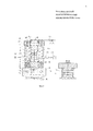
Наиболее близким по технической сущности к предлагаемому техническому решению для измерения дистанционных механических усилий в пожаровзрывоопасных производствах является пьезоэлектрический преобразователь силы [6, прототип] с дискретным выходным сигналом с использованием волоконно-оптических световодов. Данное устройство (фиг. 1, прототип) содержит два пьезоэлемента прямого действия с расположением в канале корпуса полюсами последовательным направлением, силоввводящий блок, электроды, включенные в электрическую схему, индикаторное устройство в виде прозрачного корпуса с размещенным в нем конденсатором с электропроводной частицей между его обкладками и оптические световоды, закрепленные по центру конденсатора заподлицо на внутренней поверхности корпуса ортогонально траектории частицы.The closest in technical essence to the proposed technical solution for measuring remote mechanical forces in fire and explosion hazard industries is a piezoelectric force transducer [6, prototype] with a discrete output signal using fiber optic optical fibers. This device (Fig. 1, prototype) contains two direct-action piezoelectric elements with poles in a sequential direction, a power-input unit, electrodes included in the electrical circuit, an indicator device in the form of a transparent case with a capacitor placed in it with an electrically conductive particle between its plates and optical fibers fixed in the center of the capacitor flush on the inner surface of the housing orthogonally to the particle path.
В прототипе последовательное преобразование физических величин в устройстве выполнятся по схеме:In the prototype, the sequential conversion of physical quantities in the device will be performed according to the scheme:

т.е. 
где МН - механическое напряжение, прикладываемое к преобразователю силы; ПЭЗ -пьезоэлектрический заряд (плотность электростатических зарядов) на пьезоэлементах; ЭСП - электростатический потенциал на обкладках конденсатора; АК - автоколебания электропроводной частицы в зазоре конденсатора; ВНЧ - визуальное наблюдение частицы; ДИД - дистанционное измерение деформации.where MN is the mechanical stress applied to the force transducer; PES - piezoelectric charge (density of electrostatic charges) on piezoelectric elements; ESP - electrostatic potential on the capacitor plates; AK - self-oscillation of an electrically conductive particle in the gap of the capacitor; VLF - visual observation of a particle; BIT - remote measurement of strain.
В результате преобразования физических эффектов по схеме МН → ВНЧ → ДИД появляется возможность не только наблюдать визуально автоколебания частицы и, соответственно, наблюдать процесс изменения деформации (ВНЧ), но и одновременно измерять параметры деформации дистанционно (ДИД) на большие расстояния по цепи: источник света - входной световод - электропроводная частица - выходной световод - фоторегистратор.As a result of the conversion of physical effects according to the MN → VLF → DID scheme, it becomes possible not only to visually observe self-oscillations of a particle and, accordingly, to observe the process of strain change (VLF), but also to measure the deformation parameters remotely (BIT) over long distances along the circuit: light source - input fiber - conductive particle - output fiber - photo recorder.
Конструктивно устройство (фиг. 1, прототип) содержит заполненный диэлектрической жидкостью прозрачный (оргстекло) корпус 1; металлическую рабочую часть 13 в виде цилиндрического диска; крышку 2; уплотнительную резиновую шайбу 16; верхнюю регулирующую обкладку 3 конденсатора; токопроводящую частицу 5; нижнее диэлектрическое основание 6 корпуса 1; первый нижний пьезоэлемент 7; второй верхний пьезоэлемент 21, установленный между промежуточным электродом 15 и металлической рабочей частью 13; силовводящий блок, состоящий из опорной шайбы 8, рычажного коромысла 9, подвижных роликов 10, ограничительного ролика 11 и шарнирного ролика 12. Нижняя обкладка 4 конденсатора является одновременно одним из электродов пьезоэлемента 7. Нижнее основание 6 и крышка 2 соединены с корпусом с помощью резьбы. Для дистанционной передачи информации в корпусе 1 закреплены: оптический вводный световод 18 для передачи света от источника излучения 17 в канал корпуса и выходной световод 19 для передачи света из канала в светоприемник 20. В качестве источника излучения 17 используется светодиод АЛ-107 или галогеновый источник света, а в качестве приемника излучения - фотоэлемент ФД-6К. В качестве второго пьезоэлемента использован идентичный первому цилиндрический сегнетоэлектрик титанат бария ВаТiO3. Электрическое соединение нижнего торца нижнего 7 пьезоэлемента с верхним торцом верхнего пьезоэлемента 21 осуществляется по цепи: нижний торец первого пьезоэлемента - опорная металлическая шайба 8 - рычажной механизм 9 - «земля» - металлическая штанга 14 - металлическая рабочая часть 13 -верхний торец второго пьезоэлемента. При монтаже устройства в металлическом оборудовании электрическая связь рабочей части 13 с рычажным механизмом 9 осуществляется за счет электропроводимости оборудования.Structurally, the device (Fig. 1, prototype) contains a transparent (plexiglass)
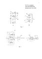
Устройство работает следующим образом. Под воздействием механического усилия P(МПа) штангой 14 относительно «земли» на рабочую часть 13 устройства, оба пьезокерамических диска будут равномерно подвергаться механическим напряжениям (первый 7 между опорной шайбой 8 и нижней обкладкой 4 конденсатора, а второй 21 между рабочей частью 13 и электродом 15). На фиг. 2 представлены эквивалентные схемы пьезоэлектрического преобразователя силы (аналог): а) - кинематическая схема; б) - электрическая схема. При расположении пьезоэлементов полюсами последовательным направлением (см. фиг. 2 а), вследствие прямого пьезоэлектрического эффекта, на обкладках обоих пьезоэлементов появятся электрические заряды, которые наводят на обкладках конденсатора электростатический потенциал (U1 - потенциал первого пьезоэлемента 7; U2 - потенциал второго пьезоэлемента 21; U1=U2=U). Поскольку электрическое соединение пьезоэлементов и конденсатора является последовательным (см. фиг. 2 б), то на обкладках конденсатора устройства напряжение будет равно как UC=U1+U2=2U. Под воздействием электростатического поля в межэлектродном пространстве частица 5 будет совершать колебательное движение, периодически касаясь обкладок конденсатора до выравнивания потенциала на электродах до порогового значения срабатывания устройства. В момент прохождения частицы через траекторию распространения светового пучка часть света будет отражаться от зеркальной поверхности частицы. При этом происходит кратковременное изменение светового потока, поступающего во второй выходной световод 19. Таким образом, излучение, идущее от источника света 17 по световоду к фоторегистратору 20, будет периодически изменяться при движении частицы, что несет информацию о ее колебательном движении и, следовательно, информацию об изменении деформации, что повышает функциональные возможности устройства, повышает пожаровзрывобезопасность и помехоустойчивость (за счет замены электоропроводников на световоды).The device operates as follows. Under the influence of mechanical force P (MPa) by the
Поскольку частота колебания частицы fЧ прямо пропорциональна наведенному от пьезоэлементов электростатическому потенциалу U на обкладках конденсатора согласно [7], то величина деформации будет пропорциональна модуляции светового потока, который светоприемником преобразуется в электрический сигнал известными способами.Since the oscillation frequency f B particles is directly proportional to the induced electrostatic potential of the piezo elements U on the capacitor plates according to [7], the amount of deformation is proportional to the modulation of the light flux which the light detector is converted into an electric signal by known methods.

где U - напряжение между обкладками конденсатора; d - расстояние между обкладками конденсатора; ε0 - диэлектрическая постоянная; ε - относительная диэлектрическая проницаемость жидкого диэлектрика между обкладками конденсатора; γс - плотность проводящей сферической частицы; r - радиус частицы.where U is the voltage between the capacitor plates; d is the distance between the capacitor plates; ε 0 is the dielectric constant; ε is the relative dielectric constant of the liquid dielectric between the capacitor plates; γ c is the density of a conducting spherical particle; r is the particle radius.
Недостатком данной конструкции прототипа при измерении параметров давления в 2-х и более точках является использование для каждого устройства 2-х измерительных линий, т.е. при измерении параметров давления в n точках, суммарное количество измерительных линий N составит N=2⋅n. Такое количество линий (световодов) является не только затратным с экономической стороны, но и более трудоемким при монтажных работах, например, в горных выработках.The disadvantage of this prototype design when measuring pressure parameters at 2 or more points is the use of 2 measurement lines for each device, i.e. when measuring pressure parameters at n points, the total number of measuring lines N will be N = 2⋅n. Such a number of lines (optical fibers) is not only costly on the economic side, but also more time-consuming during installation works, for example, in mining.
Задачей заявляемого технического решения является создание устройства, работающего на принципе последовательного преобразования механических усилий в автоколебания частицы, которое позволяет осуществлять дистанционное измерение деформации механических усилий в n точках за счет использования дискретной оптической передачи информации световодами по одной линии при значительном сокращении измерительных световодов.The objective of the proposed technical solution is to create a device that works on the principle of sequential conversion of mechanical forces into self-oscillations of a particle, which allows remote measurement of the strain of mechanical forces at n points by using discrete optical transmission of information by optical fibers along one line with a significant reduction in measuring optical fibers.
Технический результат: упрощение конструкции, экономическая целесообразность и снижение трудоемкости монтажных работ.Effect: simplification of design, economic feasibility and reduction of the complexity of installation work.
В предлагаемом техническом решении преобразователи силы по патенту №2574868 [6] в n-м количестве содержащие каждый по два пьезоэлемента прямого действия с полюсами последовательного направления, силовводящий блок, электроды, включенные в электрическую схему, индикаторное устройство в виде прозрачного корпуса с размещенным в нем конденсатором с электропроводной частицей между его обкладками и оптические световоды для дискретной передачи информации, соединены в единый оптический канал последовательно: вывод световода предыдущего преобразователя силы с вводом последующего преобразователя, а электропроводные частицы в конденсаторах выполнены различными по размеру для каждого преобразователя.In the proposed technical solution, power converters according to the patent No. 2574868 [6] in the nth quantity each containing two direct-acting piezoelectric elements with poles in a sequential direction, a power-supply unit, electrodes included in the electrical circuit, an indicator device in the form of a transparent case with it a capacitor with an electrically conductive particle between its plates and optical fibers for discrete transmission of information are connected in a single optical channel in series: the output of the fiber of the previous conversion ovatelya forces with subsequent input transducer, and the conductive particles are made in capacitors different in size for each transducer.
Соединение преобразователей в единый оптический канал позволяет сократить количество световодов N до N=n+1 вместо N=2⋅n, что упрощает конструкцию устройства, снижает себестоимость устройства и трудоемкость монтажных работ, а выполнение частиц различных по размеру для каждого преобразователя позволяет осуществлять временную модуляцию оптического сигнала при прохождении частицы через сечение световода, что позволяет выделять модулированный входной сигнал искомого преобразователя временным электронным демодулятором на выходе оптической линии.The connection of the converters into a single optical channel reduces the number of optical fibers N to N = n + 1 instead of N = 2⋅n, which simplifies the design of the device, reduces the cost of the device and the complexity of installation work, and the implementation of particles of different sizes for each converter allows temporary modulation optical signal when a particle passes through a fiber section, which makes it possible to isolate the modulated input signal of the desired converter by a temporary electronic demodulator at the optical output th line.
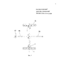
Техническое решение поясняется схемой устройства (фиг. 3), в которой схемы каждого преобразователя идентичны эквивалентной схеме прототипа (фиг. 2 а) и 2 б)), кроме электропроводной частицы. Конструктивные элементы каждого преобразователя, кроме электропроводной частицы в устройстве и прототипе также остаются без изменения.The technical solution is illustrated by the circuit of the device (Fig. 3), in which the circuit of each Converter are identical to the equivalent circuit of the prototype (Fig. 2 a) and 2 b)), except for the electrically conductive particles. The structural elements of each Converter, in addition to the electrically conductive particles in the device and prototype also remain unchanged.
Конструктивно заявляемое устройство (фиг. 3) содержит n-е количество преобразователи силы, содержащие каждый по два пьезоэлемента 7, 21 прямого действия с полюсами последовательного направления, силовводящий блок (опорная шайба 8, рычажное коромысло 9), электроды 4, 15, включенные в электрическую схему (электроды пьезоэлементов 7, 21 являются одновременно обкладками конденсатора), индикаторное устройство в виде прозрачного корпуса с размещенным в нем конденсатором с обкладками 4, 15 и электропроводной частицей 5, оптические световоды (для 1-го преобразователя: входной световод для приема светового потока 18, выходной для дискретной передачи светового потока 19; для последующих преобразователей: выходной световод предыдущего преобразователя будет являться входным световодом для последующего преобразователя и т.д.). Преобразователи силы 1-й, 2-й …n-й соединены в единый оптический канал последовательно: выводной световод предыдущего преобразователя силы с вводом последующего преобразователя, а электропроводные частицы в конденсаторах преобразователей выполнены различными по размеру (диаметру d) для каждого преобразователя (d1<.d2…dn).Structurally, the claimed device (Fig. 3) contains the nth number of force transducers, each containing two
Устройство работает следующим образом. Все преобразователи устройства от 1-го до n-го размещается в заданных местах (точках), например, при исследовании рельефа в подземных выработках шахты на заданных расстояниях L (м) друг от друга. Перед техногенным обрушением свода в выработках предварительно образуется избыточное давление в породе и в точке расположения преобразователя за счет действия силы сжатия на силовводящий блок 9 и последующего преобразования пьезоэлементами 7, 21 электрического потенциала в механическую энергию частицы в зазоре конденсатора 4, 15 устройства, - начнется колебательный процесс частицы. Модулированный по времени частицей световой сигнал от преобразователя, на который действует сила сжатия, поступит по оптической линии на детектор 20, а затем в виде электрического сигнала на временной демодулятор 21 и, после электронной обработки, на диспетчерский пульт управления для принятия оперативного решения. Для определения истинного преобразователя, который сигнализирует об опасности, и соответственно, места с которого получена информация используется принцип модуляции оптического сигнала за счет изменения размеров частиц в конденсаторах преобразователей как показано на фиг. 3.The device operates as follows. All converters of the device from the 1st to the nth are located in predetermined places (points), for example, when studying the relief in underground mine workings at given distances L (m) from each other. Before man-made collapse of the arch in the workings, overpressure is formed in the rock and at the transducer location point due to the action of the compression force on the power-introducing
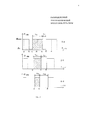
Принцип преобразования механического движения частицы в модулированный по времени оптический сигнал поясняется рисунками, приведенными на фиг. 4 (схема фрагмента преобразователя силы) и фиг. 5 (эпюры светового сигнала распределенного преобразователя силы). Модуляция сигнала производится следующим образом. При давлении на рабочую часть устройства 13 (фиг. 3), на противоположных обкладках 4, 15 конденсатора индуцируются электростатические заряды противоположных знаков и в результате возникновения электрического поля между обкладками Е (В/м) частица 5 с исходного положения (точка а, фиг. 4) начнет движение вверх до пересечения со световой осью оптического сигнала (точка б). При дальнейшем движении частицы (точка с) световой сигнал будет перекрыт и, соответственно световой поток Ф(лм) будет равен нулю (на эпюре фиг. 5 выходного сигнала 1-го преобразователя Ф=ƒ (τ), временное значение соответствует как б→с). При дальнейшем движении частицы (точка д) сигнал Ф=ƒ (τ) будет иметь максимальное значение (с → д → с), а временное значение светового сигнала будет соответствовать значению τф1. Эпюры светового сигнала для 1-го, 2-го и n-го преобразователей при автоколебании частицы (точки а, б, с, д) приведены на фиг. 5. Таким образом, при увеличении размера частиц dЧ (мм) за счет перекрытия светового потока Ф(лм) осуществляется прямая зависимость размера частиц от времени перекрытия светового потока, т.е dЧ=ƒ(τф), что тождественно времени прохождения светового потока (от τф1 для 1-го преобразователя, что соответствует минимальному значению диаметра частицы dЧмин, до τфn, что соответствует максимальному значению диаметра частицы dЧмакс для n-го преобразователя).The principle of converting the mechanical motion of a particle into a time-modulated optical signal is illustrated by the figures in FIG. 4 (diagram of a fragment of a force transducer) and FIG. 5 (diagrams of the light signal of a distributed force transducer). Modulation of the signal is as follows. When pressure is applied to the working part of the device 13 (Fig. 3), electrostatic charges of opposite signs are induced on opposite plates of the
За счет изменения по времени скважности импульсного светового потока фактически осуществляется временная модуляции входного сигнала, и после детектирования и электронной обработки модулированного сигнала демодулятором, определяется искомый преобразователь силы, на который оказывалась деформация.Due to the change in the duty cycle time of the pulsed light flux, the temporal modulation of the input signal is actually carried out, and after detection and electronic processing of the modulated signal by the demodulator, the desired force transducer, on which the deformation occurs, is determined.
Изготовление комплексной измерительной системы не представляет сложности. В качестве источника оптического излучения 17 используется светодиод АЛ-107 или галогеновый источник света, а в качестве светоприемника - фотоэлемент ФД-6К. Пьезоэлементы для преобразователей используются из цилиндрических элементов сегнетоэлектрика титаната бария ВаТiO3 или возможно использование готовых керамических пьезоэлементов от китайских зажигалок. Силовводящий блок также используется от зажигалок. В качестве оптоволоконного кабеля используется любой одноволоконный одномодовый кабель (SM 9/125, ОКТ-Д и др.) с диаметром оптической сердцевины 8-10 мкм. При изменении светового потока в заявляемом устройстве от Фмакс до Фмин коэффициент передачи потока Кср изменяется от 0,9 до 0, поэтому регистрацию выходного модулированного сигнала можно осуществлять запоминающим осциллографом, например, АСК-2034 (АСК-2067), имеющим разъем для подключения к ПК. Изготовление электропроводных сферических частиц любого размера из гранулированного полистирола изложено в технологической инструкции «Технологическая инструкция. Разрядник-индикатор РЭС-1. Изготовление электропроводных сферических частиц. Бийск, НПО «Алтай», 1988». Заявляемое устройство можно использовать в пожароопасных производствах и горных выработках, т.к. искробезопасность устройства обеспечивается за счет порционного переноса частицей электрической энергии между обкладками конденсатора, аналог описан в работе [7].The manufacture of an integrated measuring system is not difficult. An AL-107 LED or a halogen light source is used as a source of
Простое по конструкции предлагаемое устройство найдет широкое применение в угледобывающей и нефтеперерабатывающей промышленностях, в горных выработках, а также в системах прогнозирования аварийных ситуаций промышленных и техногенных катастроф. Использование преобразования световой энергии в дискретный сигнал дает возможность наиболее достоверно и надежно передавать и обрабатывать полученную информацию.The proposed device, simple in design, will find wide application in the coal mining and oil refining industries, in mining, as well as in emergency forecasting systems for industrial and industrial disasters. Using the conversion of light energy into a discrete signal makes it possible to most reliably and reliably transmit and process the received information.
Список литературы, используемый при составлении заявкиReferences used in the preparation of the application
1. Маликов С.Ф. Введение в технику измерений. М. Государственное научно-техническое издательство машиностроительной литературы, 1959, с. 178.1. Malikov S.F. Introduction to measurement technology. M. State Scientific and Technical Publishing House of Engineering Literature, 1959, p. 178.
2. Ультразвуковые преобразователи. Пер. с англ. под ред. Е. Кикучи, М., 1972. 424 С.2. Ultrasonic transducers. Per. from English under the editorship of E. Kikuchi, M., 1972. 424 S.
3. Лаврик В.Г., Михеев О.В., Казанцев В.Г. Диагностика и управление состоянием массива горных пород. - М.: Издательство MAC, 2006. - С300.3. Lavrik V.G., Mikheev O.V., Kazantsev V.G. Diagnostics and state management of rock mass. - M .: Publishing house MAC, 2006. - C300.
4. ТРУДЫ МФТИ. - 2012. - Том 4, №2. К.А. Томышев, В.А. Баган, В.А. Астапенко4. WORKS OF MIPT. - 2012. -
5. A.M. Мамедов, В.Т. Потапов, Т.В. Потапов, Е.К. Смуреев. Одноволоконные распределенные волоконно-оптические датчики физических величин и полей. - Фотон-Экспресс, 6(46) 2005.5. A.M. Mamedov, V.T. Potapov, T.V. Potapov, E.K. Smureev. Single-fiber distributed fiber-optic sensors of physical quantities and fields. - Photon Express, 6 (46) 2005.
6. Патент РФ, №2574868, (прототип), опубл. 10.02.2016, Бюл.№4.6. RF patent, No. 2574868, (prototype), publ. 02/10/2016, Bull.№4.
7. Авторское свидетельство СССР №936475, кл. Н05F 3 /00, 1982.7. USSR author's certificate No. 936475, cl.
Claims (1)
Priority Applications (1)
| Application Number | Priority Date | Filing Date | Title |
|---|---|---|---|
| RU2016144001A RU2657110C2 (en) | 2016-11-08 | 2016-11-08 | Distributed piezoelectric power converter |
Applications Claiming Priority (1)
| Application Number | Priority Date | Filing Date | Title |
|---|---|---|---|
| RU2016144001A RU2657110C2 (en) | 2016-11-08 | 2016-11-08 | Distributed piezoelectric power converter |
Publications (3)
| Publication Number | Publication Date |
|---|---|
| RU2016144001A3 RU2016144001A3 (en) | 2018-05-11 |
| RU2016144001A RU2016144001A (en) | 2018-05-11 |
| RU2657110C2 true RU2657110C2 (en) | 2018-06-08 |
Family
ID=62151971
Family Applications (1)
| Application Number | Title | Priority Date | Filing Date |
|---|---|---|---|
| RU2016144001A RU2657110C2 (en) | 2016-11-08 | 2016-11-08 | Distributed piezoelectric power converter |
Country Status (1)
| Country | Link |
|---|---|
| RU (1) | RU2657110C2 (en) |
Citations (4)
| Publication number | Priority date | Publication date | Assignee | Title |
|---|---|---|---|---|
| SU665270A1 (en) * | 1976-07-12 | 1979-05-30 | Ленинградский Ордена Трудового Красного Знамени Технологический Институт Им.Ленсовета | Dc voltage-to-pulse signal converter |
| RU2025677C1 (en) * | 1991-08-19 | 1994-12-30 | Научно-производственное объединение "Алтай" | Piezoelectric force transducer |
| EP1793197A2 (en) * | 2005-12-02 | 2007-06-06 | Riken | Micro force measuring device, micro force measuring method, and surface shape measuring probe |
| RU2574868C1 (en) * | 2014-10-27 | 2016-02-10 | Государственное образовательное учреждение высшего профессионального образования "Алтайский государственный технический университет им. И.И. Ползунова" (АлтГТУ) | Piezoelectric force converter |
-
2016
- 2016-11-08 RU RU2016144001A patent/RU2657110C2/en not_active IP Right Cessation
Patent Citations (4)
| Publication number | Priority date | Publication date | Assignee | Title |
|---|---|---|---|---|
| SU665270A1 (en) * | 1976-07-12 | 1979-05-30 | Ленинградский Ордена Трудового Красного Знамени Технологический Институт Им.Ленсовета | Dc voltage-to-pulse signal converter |
| RU2025677C1 (en) * | 1991-08-19 | 1994-12-30 | Научно-производственное объединение "Алтай" | Piezoelectric force transducer |
| EP1793197A2 (en) * | 2005-12-02 | 2007-06-06 | Riken | Micro force measuring device, micro force measuring method, and surface shape measuring probe |
| RU2574868C1 (en) * | 2014-10-27 | 2016-02-10 | Государственное образовательное учреждение высшего профессионального образования "Алтайский государственный технический университет им. И.И. Ползунова" (АлтГТУ) | Piezoelectric force converter |
Also Published As
| Publication number | Publication date |
|---|---|
| RU2016144001A3 (en) | 2018-05-11 |
| RU2016144001A (en) | 2018-05-11 |
Similar Documents
| Publication | Publication Date | Title |
|---|---|---|
| Leal-Junior et al. | Optical fiber specklegram sensors for mechanical measurements: A review | |
| Sun et al. | Investigation of the dynamic strain responses of sandstone using multichannel fiber-optic sensor arrays | |
| CN104343466B (en) | All-fiber coal mine safety monitoring system | |
| CN103727980A (en) | Optical fiber sensing system for monitoring slope landslide condition in real time | |
| Mesquita et al. | Optical sensors for bond-slip characterization and monitoring of RC structures | |
| CN109269467A (en) | A kind of fiber grating settlement monitoring device for bridge pre-pressing bracket settlement monitoring | |
| NO20170777A1 (en) | Offshore electromagnetic reservoir monitoring | |
| Madi et al. | Research of fiber-optic displacement sensors | |
| US10302796B2 (en) | Onshore electromagnetic reservoir monitoring | |
| RU2657110C2 (en) | Distributed piezoelectric power converter | |
| TR2023005670A2 (en) | FIBER OPTIC SENSOR FOR TRI-AXIS DISPLACEMENT MEASUREMENT | |
| US10927661B2 (en) | Using electro acoustic technology to determine annulus pressure | |
| CN108592871B (en) | Storage tank foundation settlement monitoring device and system | |
| CN109682322A (en) | Experiment porch microstrain real-time monitoring device and method under a kind of vacuum environment | |
| CN119511475B (en) | An FBG fiber optic sensing cable for monitoring the internal mechanical behavior of slopes | |
| Karthik et al. | Review on low-cost wireless communication systems for slope stability monitoring in opencast mines | |
| CN105759307A (en) | Great earthquake inoculation process based on earthquake sound detection method and impending earthquake monitoring probe | |
| Ferentinou | Sinkhole collapse propagation studies through instrumented small-scale physical models | |
| RU2574868C1 (en) | Piezoelectric force converter | |
| Mekhtiev et al. | A quasi-distributed fiber-optical monitoring system for movement of roof strata in mines | |
| Liang et al. | A hydraulic fiber Bragg grating force sensor and its monitoring system for axial bolt load measurement in anchorage engineering | |
| Mekhtiyev et al. | Fiber optics based system of monitoring load-bearing building structures | |
| Bernini et al. | Distributed strain measurement along a concrete beam via stimulated Brillouin scattering in optical fibers | |
| Yang et al. | Fibre optic sensing based slope crest tension crack monitoring system for surface mines | |
| CN207197457U (en) | A kind of distribution type fiber-optic dough deformation sensor |
Legal Events
| Date | Code | Title | Description |
|---|---|---|---|
| MM4A | The patent is invalid due to non-payment of fees |
Effective date: 20191109 |