RU2665503C1 - Built-in tachograph - Google Patents
Built-in tachograph Download PDFInfo
- Publication number
- RU2665503C1 RU2665503C1 RU2016127570A RU2016127570A RU2665503C1 RU 2665503 C1 RU2665503 C1 RU 2665503C1 RU 2016127570 A RU2016127570 A RU 2016127570A RU 2016127570 A RU2016127570 A RU 2016127570A RU 2665503 C1 RU2665503 C1 RU 2665503C1
- Authority
- RU
- Russia
- Prior art keywords
- built
- bath
- protection module
- bracket
- housing
- Prior art date
Links
- 239000002184 metal Substances 0.000 claims description 9
- 239000000284 extract Substances 0.000 claims 1
- 230000001681 protective effect Effects 0.000 abstract 4
- 230000000694 effects Effects 0.000 abstract 1
- 238000005259 measurement Methods 0.000 abstract 1
- 239000000126 substance Substances 0.000 abstract 1
- 238000000034 method Methods 0.000 description 3
- 229910000831 Steel Inorganic materials 0.000 description 2
- 238000000605 extraction Methods 0.000 description 2
- 238000004519 manufacturing process Methods 0.000 description 2
- 239000010959 steel Substances 0.000 description 2
- 210000002105 tongue Anatomy 0.000 description 2
- 230000001419 dependent effect Effects 0.000 description 1
- 239000012634 fragment Substances 0.000 description 1
- 238000002347 injection Methods 0.000 description 1
- 239000007924 injection Substances 0.000 description 1
- 238000009434 installation Methods 0.000 description 1
- 230000010354 integration Effects 0.000 description 1
- 230000003287 optical effect Effects 0.000 description 1
- 230000000284 resting effect Effects 0.000 description 1
Images
Classifications
-
- G—PHYSICS
- G01—MEASURING; TESTING
- G01P—MEASURING LINEAR OR ANGULAR SPEED, ACCELERATION, DECELERATION, OR SHOCK; INDICATING PRESENCE, ABSENCE, OR DIRECTION, OF MOVEMENT
- G01P1/00—Details of instruments
- G01P1/02—Housings
-
- G—PHYSICS
- G01—MEASURING; TESTING
- G01P—MEASURING LINEAR OR ANGULAR SPEED, ACCELERATION, DECELERATION, OR SHOCK; INDICATING PRESENCE, ABSENCE, OR DIRECTION, OF MOVEMENT
- G01P1/00—Details of instruments
- G01P1/02—Housings
- G01P1/026—Housings for speed measuring devices, e.g. pulse generator
-
- G—PHYSICS
- G01—MEASURING; TESTING
- G01P—MEASURING LINEAR OR ANGULAR SPEED, ACCELERATION, DECELERATION, OR SHOCK; INDICATING PRESENCE, ABSENCE, OR DIRECTION, OF MOVEMENT
- G01P1/00—Details of instruments
- G01P1/12—Recording devices
- G01P1/122—Speed recorders
-
- G—PHYSICS
- G07—CHECKING-DEVICES
- G07C—TIME OR ATTENDANCE REGISTERS; REGISTERING OR INDICATING THE WORKING OF MACHINES; GENERATING RANDOM NUMBERS; VOTING OR LOTTERY APPARATUS; ARRANGEMENTS, SYSTEMS OR APPARATUS FOR CHECKING NOT PROVIDED FOR ELSEWHERE
- G07C7/00—Details or accessories common to the registering or indicating apparatus of groups G07C3/00 and G07C5/00
-
- G—PHYSICS
- G12—INSTRUMENT DETAILS
- G12B—CONSTRUCTIONAL DETAILS OF INSTRUMENTS, OR COMPARABLE DETAILS OF OTHER APPARATUS, NOT OTHERWISE PROVIDED FOR
- G12B9/00—Housing or supporting of instruments or other apparatus
- G12B9/02—Casings; Housings; Cabinets
-
- H—ELECTRICITY
- H05—ELECTRIC TECHNIQUES NOT OTHERWISE PROVIDED FOR
- H05K—PRINTED CIRCUITS; CASINGS OR CONSTRUCTIONAL DETAILS OF ELECTRIC APPARATUS; MANUFACTURE OF ASSEMBLAGES OF ELECTRICAL COMPONENTS
- H05K5/00—Casings, cabinets or drawers for electric apparatus
- H05K5/02—Details
- H05K5/0208—Interlock mechanisms; Means for avoiding unauthorised use or function, e.g. tamperproof
-
- H—ELECTRICITY
- H05—ELECTRIC TECHNIQUES NOT OTHERWISE PROVIDED FOR
- H05K—PRINTED CIRCUITS; CASINGS OR CONSTRUCTIONAL DETAILS OF ELECTRIC APPARATUS; MANUFACTURE OF ASSEMBLAGES OF ELECTRICAL COMPONENTS
- H05K7/00—Constructional details common to different types of electric apparatus
- H05K7/14—Mounting supporting structure in casing or on frame or rack
- H05K7/1401—Mounting supporting structure in casing or on frame or rack comprising clamping or extracting means
Landscapes
- Physics & Mathematics (AREA)
- General Physics & Mathematics (AREA)
- Engineering & Computer Science (AREA)
- Microelectronics & Electronic Packaging (AREA)
- Computer Security & Cryptography (AREA)
- Time Recorders, Dirve Recorders, Access Control (AREA)
- Casings For Electric Apparatus (AREA)
Abstract
Description
Изобретение касается встраиваемого тахографа, в частности для автомобиля, имеющего встраиваемый корпус в форме прямоугольного параллелепипеда и расположенную во встраиваемом корпусе печатную плату системы приборов.The invention relates to a built-in tachograph, in particular for a car having a built-in case in the form of a rectangular parallelepiped and a printed circuit board of the instrument system located in the built-in case.
Такой встраиваемый тахограф известен как цифровой тахограф для автомобиля. Для простого встраивания в автомобиль, а также расположения в автомобиле, не мешающего пассажирам транспортного средства, этот тахограф выполнен в виде встраиваемого прибора. Встраиваемый тахограф встраивается в автомобиле в стандартизированную монтажную шахту, например, в так называемом формате отсека радиоприемника 1 DIN. Встраиваемый корпус во встроенном в автомобиль состоянии расположен в монтажной шахте, за исключением обращенной к внутреннему пространству транспортного средства, обычно содержащей элементы обслуживания фронтальной стенки корпуса.Such an embedded tachograph is known as a digital tachograph for a car. For easy integration into the car, as well as the location in the car that does not interfere with the passengers of the vehicle, this tachograph is made in the form of a built-in device. The built-in tachograph is integrated in the vehicle into a standardized mounting shaft, for example, in the so-called 1 DIN radio compartment format. The built-in housing in a state integrated into the vehicle is located in the mounting shaft, with the exception of facing the interior of the vehicle, usually containing service elements of the front wall of the housing.
Особым типом встраиваемого тахографа является так называемый прибор контроля ЕС (EU). Вообще встраиваемый тахограф может также называться прибором для записи данных транспортного средства.A special type of built-in tachograph is the so-called EU control device. In general, an embedded tachograph may also be called a vehicle data recorder.
В тахографе запоминаются и обрабатываются специфические данные водителя и/или транспортного средства, а также специфические данные поездки. При этом имеет большое значение, чтобы обеспечивалась высокая защита от манипулирования данными как для защиты самих данных, так и для защиты обработки данных.The tachograph stores and processes the specific data of the driver and / or vehicle, as well as the specific data of the trip. At the same time, it is of great importance to ensure high protection against data manipulation both for protecting the data itself and for protecting data processing.
Известно, что для этого на печатной плате системы приборов предусматривается устройство защиты, которое препятствует неразрешенной атаке или вмешательству в запоминаемые данные, а также обработку данных. Интеграция устройства защиты в архитектуру печатной платы системы приборов является трудоемкой, и адаптация устройства защиты в случае необходимости вряд ли возможна.It is known that for this purpose a protection device is provided on the printed circuit board of the instrument system that prevents an unauthorized attack or interference with stored data, as well as data processing. Integrating a protection device into the PCB architecture of a device system is time-consuming, and adapting a protection device if necessary is hardly possible.
Поэтому в основе изобретения лежит задача, создать встраиваемый тахограф вышеназванного рода, который обладает высокой защитой от манипулирования данными при одновременно простой конструкции прибора.Therefore, the basis of the invention is the task of creating an embedded tachograph of the aforementioned kind, which has high protection against data manipulation with at the same time a simple device design.
Задача в соответствии с изобретением решается с помощью встраиваемого тахографа вышеназванного рода и таким образом, что с печатной платой системы приборов электрически соединен расположенный внутри встраиваемого корпуса модуль защиты, и что наружная стенка встраиваемого корпуса имеет выемку стенки, причем в этой выемке стенки расположена ванна, вмещающая в себя модуль защиты и имеющая поворотную скобу, причем эта поворотная скоба обладает возможностью поворота вокруг оси поворота между первым положением, фиксирующим модуль защиты в рабочем положении модуля в ванне, и вторым положением, высвобождающим модуль защиты с целью его извлечения из ванны.The problem in accordance with the invention is solved with the help of the built-in tachograph of the above kind and in such a way that the protection module located inside the built-in case is electrically connected to the circuit board of the instrument system and that the outer wall of the built-in case has a recess in the wall, and a bath holding the security module and having a swivel bracket, and this swivel bracket has the ability to rotate around the axis of rotation between the first position fixing the protection module in the operating position of the module in the bath and the second position releasing the protection module in order to remove it from the bath.
Особым преимуществом изобретения является, что модуль защиты может изготавливаться независимо от печатной платы системы приборов и позднее особенно простым образом добавляться к встраиваемому тахографу. Для этого модуль защиты вставляется в ванну сквозь выемку стенки. При этом встраиваемый тахограф, за исключением модуля защиты, может полностью изготавливаться до того, как в заключение во встраиваемый тахограф будет инсталлирован модуль защиты. Для этого не требуется еще раз открывать встраиваемый корпус, а для инсталляции модуля защиты используется только выемка стенки.A particular advantage of the invention is that the protection module can be manufactured independently of the printed circuit board of the instrument system and later added in an especially simple way to the built-in tachograph. For this, the protection module is inserted into the bathtub through the recess of the wall. In this case, the built-in tachograph, with the exception of the protection module, can be completely manufactured before the protection module is installed in the built-in tachograph in conclusion. To do this, you do not need to open the built-in housing again, and only the wall recess is used to install the protection module.
Существенным преимуществом является при этом предусмотренная в соответствии с изобретением поворотная скоба. Посредством этой поворотной скобы модуль защиты не только фиксируется, когда он находится в рабочем положении модуля, но и, кроме того, упрощается извлечение модуля защиты из ванны и вместе с тем из встраиваемого корпуса, например, с целью замены или технического обслуживания модуля защиты. В рабочем положении модуля модуль защиты находится внутри встраиваемого корпуса, и существует электрическое соединение, например, с помощью штекерного соединения, между модулем защиты и печатной платой системы приборов. Фиксация модуля защиты в рабочем положении модуля в ванне с помощью поворотной скобы представляет собой по меньшей мере чисто механическую фиксацию и препятствует по меньшей мере выпадению модуля защиты из ванны. Поворотная скоба закрыта.A significant advantage is the swivel bracket provided in accordance with the invention. By means of this swivel bracket, the protection module is not only fixed when it is in the operating position of the module, but also, it is easier to remove the protection module from the bath and at the same time from the built-in housing, for example, to replace or maintain the protection module. In the operating position of the module, the protection module is located inside the built-in housing, and there is an electrical connection, for example, via a plug connection, between the protection module and the printed circuit board of the instrument system. Fixation of the protection module in the operating position of the module in the bath with the help of a rotary bracket represents at least purely mechanical fixation and prevents at least the protection module from falling out of the bath. Swivel bracket closed.
В положении извлечения модуля модуль защиты по меньшей мере частично находится вне встраиваемого корпуса. Поворотная скоба открыта. В положении извлечения модуля модуль защиты может извлекаться из встраиваемого корпуса. Извлечение модуля защиты из встраиваемого корпуса одновременно включает в себя удаление модуля защиты от встраиваемого корпуса. Кроме того, при вставке модуля защиты во встраиваемый корпус модуль защиты сначала приводится в положение извлечения модуля. После этого поворотная скоба поворачивается (то есть поворотная скоба закрывается), и при этом модуль защиты приводится в рабочее положение модуля.In the ejection position of the module, the protection module is at least partially located outside the integrated housing. Swivel bracket open. In the eject position of the module, the protection module can be removed from the built-in housing. Removing the protection module from the embedded enclosure simultaneously includes removing the protection module from the embedded enclosure. In addition, when the protection module is inserted into the built-in housing, the protection module is first brought into the module removal position. After that, the swivel bracket rotates (that is, the swivel bracket closes), and the protection module is brought into the operating position of the module.
Изобретение позволяет простым образом защищенно и надежно вставлять и извлекать модуль защиты в, соответственно, из встраиваемого корпуса. С помощью изобретения можно предпочтительно избежать перекоса при необходимости замыкаемых, соответственно, размыкаемых электрических соединений между модулем защиты и остальным встраиваемым тахографом.The invention allows a simple and secure way to securely insert and remove the protection module in, respectively, from the built-in housing. By means of the invention, it is possible to preferably avoid skewing, if necessary, of lockable, respectively, breakable electrical connections between the protection module and the rest of the built-in tachograph.
Модуль защиты включает в себя ядро техники защиты встраиваемого тахографа. В частности, модуль защиты может быть ответственным за кодирование данных, запоминаемых и обрабатываемых во встраиваемом тахографе. Наряду с техникой защиты, которая, в частности, выполняет криптографические функции, модуль защиты может также, например, иметь спутниковую систему определения местоположения, такую как, например, система GPS или система GLONASS, благодаря чему предпочтительно становится возможным определение местоположения автомобиля.The protection module includes the core protection technology of the embedded tachograph. In particular, the security module may be responsible for encoding data stored and processed in the embedded tachograph. In addition to the security technique, which, in particular, performs cryptographic functions, the security module may also, for example, have a satellite positioning system, such as, for example, a GPS system or a GLONASS system, whereby it is preferably possible to determine the location of a vehicle.
С помощью изобретения особенно несложно возможна последующая замена модуля защиты, например, с целью снабжения встраиваемого тахографа обновленной техникой защиты. Другим преимуществом является то, что в результате ставшего возможным благодаря изобретению независимого изготовления модуля защиты и остального встраиваемого тахографа, то есть встраиваемого тахографа без модуля защиты, техника защиты может защищаться и сохраняться в тайне отдельно от других элементов встраиваемого тахографа.With the help of the invention, it is especially easy to subsequently replace the protection module, for example, in order to supply the embedded tachograph with updated protection technology. Another advantage is that as a result of the independent invention made possible to manufacture the protection module and the rest of the built-in tachograph, that is, the built-in tachograph without a protection module, the protection technique can be protected and kept secret separately from other elements of the built-in tachograph.
Выемка наружной стенки встраиваемого корпуса предлагаемого изобретением встраиваемого тахографа предпочтительно предусмотрена в наружной стенке встраиваемого корпуса, причем эта наружная стенка обращена от фронтальной стенки встраиваемого корпуса, то есть представляет собой наружную стенку, не являющуюся фронтальной стенкой корпуса. Например, выемка стенки находится в наружной стенке корпуса, расположенной на верхней стороне встраиваемого корпуса. Так как фронтальная стенка корпуса во встроенном состоянии, то есть при встраиваемом тахографе, встроенном в автомобиль, является единственной наружной стенкой встраиваемого корпуса, которая непосредственно доступна, выемка стенки предпочтительно скрыта и просто так не доступна, благодаря чему затрудняется нежелательный, возможно, запланированный с намерением манипуляции доступ к модулю защиты.The recess of the outer wall of the built-in housing of the embedded tachograph according to the invention is preferably provided in the outer wall of the built-in housing, this external wall facing away from the front wall of the built-in housing, that is, it is an external wall that is not the front wall of the housing. For example, the recess of the wall is in the outer wall of the housing located on the upper side of the built-in housing. Since the front wall of the housing in the built-in state, that is, with the built-in tachograph integrated in the car, is the only external wall of the built-in housing that is directly accessible, the recess of the wall is preferably hidden and just not accessible, making it difficult for the unwanted, possibly planned with intent manipulation access to the protection module.
Встраиваемый корпус предлагаемого изобретением встраиваемого тахографа предпочтительно представляет собой металлический корпус, например, корпус из листовой стали. При этом отдельные элементы встраиваемого корпуса могут также, например, состоять из пластмассы. В частности, фронтальная стенка корпуса может состоять из пластмассы или иметь накладку из пластмассы, которая является составной частью фронтальной стенки корпуса. Наружная стенка корпуса, имеющая выемку стенки, предпочтительно представляет собой металлическую стенку, например, стенку из листовой стали. Предпочтительно ванна удерживается наружной стенкой корпуса, в частности на краю выемки стенки.The built-in housing of the embedded tachograph according to the invention is preferably a metal housing, for example, a sheet steel housing. In this case, the individual elements of the built-in housing may also, for example, consist of plastic. In particular, the front wall of the housing may consist of plastic or have an overlay of plastic, which is an integral part of the front wall of the housing. The outer wall of the housing having a recess of the wall, preferably is a metal wall, for example, a wall of sheet steel. Preferably, the bath is held by the outer wall of the housing, in particular on the edge of the recess of the wall.
Преимуществом в изобретении является также то, что модуль защиты вследствие своего расположения в ванне удален от печатной платы системы приборов. Благодаря этому существенно снижается опасность нежелательного взаимного влияния электронных компонентов на печатной плате системы приборов и электронных компонентов модуля защиты при эксплуатации встраиваемого тахографа.An advantage in the invention is also that the protection module due to its location in the bath is remote from the printed circuit board of the instrument system. This significantly reduces the risk of unwanted mutual influence of electronic components on the printed circuit board of the instrument system and the electronic components of the protection module during operation of the built-in tachograph.
Встраиваемый тахограф встраивается в монтажную шахту автомобиля, соответствующую размерам встраиваемого корпуса, например, в приборном щитке, средней консоли или обшивке на потолке крыши автомобиля. Предпочтительно автомобиль представляет собой автомобиль промышленного назначения, в частности, грузовой автомобиль, и встраивание встраиваемого тахографа осуществляется в кабине водителя автомобиля промышленного назначения, соответственно, грузового автомобиля. Встраиваемый корпус в форме прямоугольного параллелепипеда имеет формат отсека радиоприемника 1 DIN по DIN ISO 7736.The built-in tachograph is built into the vehicle’s mounting shaft corresponding to the dimensions of the built-in body, for example, in the instrument panel, middle console or the roof lining of the car. Preferably, the vehicle is an industrial vehicle, in particular a lorry, and embedding of the built-in tachograph is carried out in the driver's cab of an industrial vehicle or a lorry. The built-in enclosure in the shape of a rectangular parallelepiped has the format of the radio compartment 1 DIN according to DIN ISO 7736.
Дополнительные усовершенствования изобретения указаны в зависимых пунктах формулы изобретения.Further improvements to the invention are indicated in the dependent claims.
По одному из предпочтительных усовершенствований изобретения поворотная скоба на расстоянии от оси поворота имеет по меньшей мере один приподнимающий выступ, упирающийся в модуль защиты. Вследствие удаленного от оси поворота расположения приподнимающего выступа возникает рычаг, посредством которого модуль защиты при повороте поворотной скобы приподнимается относительно ванны, так что модуль защиты в своем положении извлечения может легко браться и извлекаться из встраиваемого корпуса. Приподнимающий выступ приподнимает модуль защиты при повороте поворотной скобы в его второе положение и по меньшей мере частично вынимает из ванны.According to one of the preferred improvements of the invention, the pivot bracket at a distance from the pivot axis has at least one lifting protrusion abutting against the protection module. Due to the location of the lifting protrusion remote from the pivot axis, a lever arises by which the protection module is raised relative to the bath when the pivot bracket is rotated, so that the protection module in its ejection position can be easily taken and removed from the built-in housing. The raising protrusion lifts the protection module when the pivot bracket is rotated to its second position and is at least partially removed from the bath.
Особенно стабильное и удобное в обслуживании расположение получается, если, по другому предпочтительному усовершенствованию изобретения, поворотная скоба имеет спинку скобы и две отходящие от спинки скобы лапки скобы, при этом ось поворота проходит через обращенные от спинки скобы концы лапок скобы. Предпочтительно ось поворота проходит параллельно спинке скобы и/или перпендикулярно лапкам скобы.A particularly stable and easy-to-maintain arrangement is obtained if, according to another preferred improvement of the invention, the pivot bracket has a bracket back and two legs of the bracket extending from the back of the bracket, while the pivot axis passes through the ends of the bracket legs of the bracket. Preferably, the axis of rotation extends parallel to the back of the bracket and / or perpendicular to the legs of the bracket.
Для особенно простой и компактной конструкции прибора при высокой долговечности предпочтительно, если по одному из усовершенствований изобретения указанный по меньшей мере один приподнимающий выступ расположен между осью поворота и спинкой скобы. Предпочтительно приподнимающий выступ расположен на лапке скобы.For a particularly simple and compact design of the device with high durability, it is preferable if, according to one of the improvements of the invention, said at least one lifting protrusion is located between the pivot axis and the back of the bracket. Preferably, the raising protrusion is located on the tab of the bracket.
В соответствии с одним из предпочтительных усовершенствований изобретения на каждой лапке скобы расположен приподнимающий выступ, упирающийся в модуль защиты. Таким образом возможно особенно равномерное и эффективное приложение к модулю защиты силы для приподнимания модуля защиты. Предпочтительно приподнимающие выступы одинаково удалены от оси поворота.In accordance with one of the preferred improvements of the invention on each tab of the bracket is a lifting protrusion, abutting against the protection module. In this way, a particularly uniform and effective application of force to the protection module for lifting the protection module is possible. Preferably, the raising projections are equally distant from the pivot axis.
Можно было бы представить себе, что модуль защиты электрически соединен с печатной платой системы приборов, например, посредством паяного кабельного соединения. Для особенно простого монтажа и демонтажа модуля защиты внутрь встраиваемого корпуса, соответственно, из встраиваемого корпуса, напротив, предпочтительно, если, по другому усовершенствованию изобретения, в дне ванны расположен первый штекерный контакт, электрически соединенный с печатной платой системы приборов, и если модуль защиты имеет соответствующий первому штекерному контакту второй штекерный контакт, при этом первый штекерный контакт и второй штекерный контакт у модуля защиты, находящегося в своем рабочем положении, образуют электрическое штекерное соединение. Первый штекерный контакт может, в частности, представлять собой гнездовую колодку. Второй штекерный контакт может, в частности, представлять собой штекерную колодку. При этом также возможно, чтобы, наоборот, первый штекерный контакт представлял собой штекерную колодку, а второй штекерный контакт - гнездовую колодку.One could imagine that the protection module is electrically connected to the printed circuit board of the instrument system, for example, by means of a soldered cable connection. For a particularly simple installation and removal of the protection module inside the built-in housing, respectively, from the built-in housing, on the contrary, it is preferable if, according to another improvement of the invention, the first plug contact is located in the bottom of the bathtub, which is electrically connected to the circuit board of the instrument system, and if the protection module has the second plug contact corresponding to the first plug contact, wherein the first plug contact and the second plug contact of the protection module in its operating position form electrical plug connection. The first plug contact may, in particular, be a socket block. The second plug contact may, in particular, be a plug connector. It is also possible that, on the contrary, the first plug contact is a plug-in connector, and the second plug contact is a socket plug.
Первый штекерный контакт, например, посредством гибкого электрического провода, например, так называемого Starflex-элемента или так называемой FPC-пленки (FPC=Flexible Printed Circuit=гибкая печатная плата) может быть соединен с печатной платой системы приборов. Первый штекерный контакт может быть, например, расположен на свободном и незакрепленном в ванне конце такого гибкого электрического провода (и при этом незакрепленно лежать в дне ванны). Однако в соответствии с одним из предпочтительных усовершенствований изобретения первый штекерный контакт неподвижно, то есть жестко, установлен на дне ванны. При этом первый штекерный контакт может быть, например, закреплен на внутренней стороне дна ванны, обращенной к модулю защиты. Но возможно также, чтобы первый штекерный контакт был, например, закреплен на наружной стороне дна ванны, обращенной от модуля защиты, и пронизывал выемку дна ванны. Электрическое соединение первого штекерного контакта с печатной платой системы приборов в двух вышеназванных случаях может осуществляться, например, посредством вышеназванного гибкого электрического провода или, например, посредством жестких электрических проводов.The first plug contact, for example, by means of a flexible electric wire, for example, a so-called Starflex element or a so-called FPC film (FPC = Flexible Printed Circuit = flexible printed circuit board) can be connected to a printed circuit board of the instrument system. The first plug contact may, for example, be located on the free and loose end of the flexible electric wire in the bath (and lie loose in the bottom of the bath). However, in accordance with one of the preferred improvements of the invention, the first plug contact is stationary, that is, rigidly mounted on the bottom of the bath. In this case, the first plug contact may, for example, be fixed on the inside of the bottom of the bath facing the protection module. But it is also possible that the first plug contact is, for example, fixed on the outside of the bottom of the bath, facing away from the protection module, and penetrates the recess of the bottom of the bath. The electrical connection of the first plug contact with the printed circuit board of the instrument system in the two above-mentioned cases can be carried out, for example, by means of the aforementioned flexible electric wires or, for example, by means of hard electric wires.
Предпочтительно изготовление встраиваемого тахографа может дополнительно упрощаться, если, по другому усовершенствованию изобретения, первый штекерный контакт неподвижно установлен на печатной плате системы приборов и пронизывает дно ванны через выемку в дне ванны.Preferably, the manufacture of an embedded tachograph can be further simplified if, according to another improvement of the invention, the first plug contact is fixedly mounted on the circuit board of the instrument system and penetrates the bottom of the bath through the recess in the bottom of the bath.
В соответствии с другим предпочтительным усовершенствованием изобретения указанный по меньшей мере один приподнимающий выступ расположен в непосредственной близости от штекерного соединения. Благодаря этому при приподнимании модуля защиты с целью его извлечения из ванны становится возможным ввод сил без перекоса в штекерное соединение для одновременного с приподниманием модуля защиты разъединения штекерного соединения. При штекерном соединении, выполненном в виде гнездовой колодки и штекерной колодки, приподнимающий выступ предпочтительно находится в продольной протяженности гнездовой и штекерной колодки, будучи расположен в линию с гнездовой и штекерной колодкой.In accordance with another preferred refinement of the invention, said at least one lifting protrusion is located in the immediate vicinity of the plug connection. Due to this, when lifting the protection module in order to remove it from the bath, it becomes possible to input forces without distortion into the plug connection for simultaneously with lifting the protection module to disconnect the plug connection. With a plug connection made in the form of a socket block and a plug block, the raising protrusion is preferably in the longitudinal extent of the socket and plug block, being located in line with the socket and plug block.
По другому предпочтительному усовершенствованию изобретения ванна представляет собой пластмассовую деталь, а поворотная скоба - пластмассовую деталь или металлическую деталь. Например, ванна может представлять собой деталь, отлитую под давлением из пластмассы. Выполненная в виде пластмассовой детали поворотная скоба имеет предпочтительно по меньшей мере один корытообразный приподнимающий выступ, «корыто» которого соответствует наружному контуру модуля защиты таким образом, что модуль защиты в своем рабочем положении прилегает поверхностью к приподнимающему выступу. Поворотная скоба в виде пластмассовой детали может представлять собой, например, пластмассовую деталь, отлитую под давлением. Поворотная скоба, выполненная в виде металлической детали, имеет предпочтительно по меньшей мере один приподнимающий выступ в виде язычка. Поворотная скоба в виде металлической детали может представлять собой, например, листовую гнутую в штампе деталь.According to another preferred refinement of the invention, the bath is a plastic part and the pivot bracket is a plastic part or a metal part. For example, the bath may be a plastic injection molded part. The swivel bracket, made in the form of a plastic part, preferably has at least one trough-shaped lifting protrusion, the “trough” of which corresponds to the outer contour of the protection module in such a way that the protection module is in contact with the surface of the lifting protrusion. The swivel bracket in the form of a plastic part can be, for example, a plastic part, molded under pressure. The swivel bracket, made in the form of a metal part, preferably has at least one lifting tab in the form of a tongue. The swivel bracket in the form of a metal part can be, for example, a sheet metal part bent in a stamp.
В частности, для очень хорошей защиты модуля защиты от неправомочного доступа предпочтительно, если, по другому усовершенствованию изобретения, ванна закрыта крышкой стенки, закрепленной на наружной стенке корпуса, при этом поворотная скоба повернута в свое первое положение, а модуль защиты расположен в своем рабочем положении. Таким образом, модуль защиты расположен во встраиваемом корпусе в ванне полностью недоступно снаружи встраиваемого корпуса, без удаления крышки стенки.In particular, for very good protection of the protection module against unauthorized access, it is preferable if, according to another improvement of the invention, the bathtub is closed by a wall cover fixed to the outer wall of the housing, while the pivoting bracket is turned to its first position and the protection module is located in its working position . Thus, the protection module is located in the built-in housing in the bath is completely inaccessible from the outside of the built-in housing, without removing the wall cover.
Примеры осуществления изобретения изображены на схематичных чертежах и ниже описываются подробнее. Показано:Examples of carrying out the invention are shown in schematic drawings and are described in more detail below. Shown:
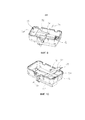
фиг.1: встраиваемый тахограф на виде в перспективе;figure 1: built-in tachograph in perspective view;
фиг.2: вид сечения фрагмента, включающего в себя модуль защиты и ванну встраиваемого тахографа в соответствии с фиг.1;figure 2: cross-sectional view of a fragment that includes a protection module and a bathtub built-in tachograph in accordance with figure 1;
фиг.3: ванна с поворотной скобой и модулем защиты, на виде в перспективе;figure 3: bath with a swivel bracket and a protection module, in perspective view;
фиг.4: ванна в соответствии с фиг.3, без модуля защиты, на виде в перспективе;figure 4: bathtub in accordance with figure 3, without a protection module, in perspective view;
фиг.5: ванна в соответствии с фиг.3, с открытой поворотной скобой, на виде в перспективе;figure 5: bath in accordance with figure 3, with an open swivel bracket, in perspective view;
фиг.6: другая ванна с закрытой поворотной скобой, на виде в перспективе;6: another bath with a closed swivel bracket, in perspective view;
фиг.7: ванна в соответствии с фиг.6, с открытой поворотной скобой, на виде в перспективе;Fig.7: bath in accordance with Fig.6, with an open swivel bracket, in perspective view;
фиг.8: ванна в соответствии с фиг.6, с модулем защиты, на виде в перспективе;Fig. 8: a bathtub according to Fig. 6, with a protection module, in perspective view;
фиг.9: еще одна ванна с закрытой поворотной скобой, на виде в перспективе;Fig.9: another bath with a closed swivel bracket, in perspective view;
фиг.10: ванна в соответствии с фиг.9, с открытой поворотной скобой, на виде в перспективе.figure 10: bathtub in accordance with figure 9, with an open swivel bracket, in perspective view.
Соответствующие друг другу элементы на всех фигурах снабжены одинаковыми ссылочными обозначениями.The elements corresponding to each other in all figures are provided with the same reference signs.
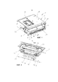
На фиг.1 на виде в перспективе показан встраиваемый тахограф 1 для автомобиля. Встраиваемый тахограф 1 имеет встраиваемый корпус 2 в форме прямоугольного параллелепипеда, и этот встраиваемый корпус 2 имеет фронтальную стенку 4 корпуса. Во встраиваемом корпусе 2 расположена печатная плата 6 системы приборов, на которой установлены электронные компоненты, необходимые для эксплуатации встраиваемого тахографа 1.Figure 1 in a perspective view shows a built-in tachograph 1 for a car. The built-in tachograph 1 has a built-in case 2 in the form of a rectangular parallelepiped, and this built-in case 2 has a front wall 4 of the case. In the built-in case 2 there is a printed
Кроме того, на фиг.1 во фронтальной стенке 4 корпуса показаны выемка 8 для не изображенного здесь подробно оптического дисплейного устройства, выемка 10 для не изображенного здесь подробно конструктивного узла принтера, две выемки 12, 12' для ввода и вывода не изображенных здесь подробно карт данных, выемка 14 для не изображенного здесь подробно штекерного гнезда, а также выемки 16, 16', 16'', 16''' для не изображенных здесь подробно клавиш обслуживания.In addition, in FIG. 1, a recess 8 for an optical display device not shown here in detail is shown in a front wall 4 of the case, a
Электрически соединенный с печатной платой 6 системы приборов и расположенный внутри встраиваемого корпуса 2 электронный модуль 20 защиты изображен на фиг.2. Модуль 20 защиты в этом примере осуществления включает в себя, наряду с техникой защиты встраиваемого тахографа 1, также спутниковую систему определения местоположения.Electrically connected to the printed
Обращенная от фронтальной стенки 4 корпуса (см. фиг.1) наружная стенка 18 корпуса, которая в этом примере осуществления представляет собой наружную стенку 18 корпуса, расположенную на верхней сторон встраиваемого корпуса 2, имеет выемку 22 стенки. В выемке 22 стенки расположена ванна 26, вмещающая в себя модуль 20 защиты и закрытая крышкой 24 стенки, закрепленной на наружной стенке 18 корпуса.The outer wall 18 of the housing, facing away from the front wall 4 of the housing (see FIG. 1), which in this embodiment is the outer wall of the housing 18 located on the upper sides of the built-in housing 2, has a
Модуль 20 защиты находится в рабочем положении модуля. При этом модуль 20 защиты полностью вставлен в ванну 26, и он электрически соединен с печатной платой 6 системы приборов. Ванна 26 имеет поворотную скобу 28, которая на фиг.2 показана в первом положении, фиксирующем модуль 20 защиты в рабочем положении модуля в ванне 26.The
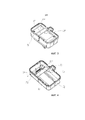
Ванна 26, имеющая похожую поворотную скобу 28, показана на фиг.3. На этом изображении поворотная скоба 28 также находится в первом положении, фиксирующем модуль 20 защиты в рабочем положении модуля в ванне 26. Для дальнейшего пояснения модуль защиты на фиг.4 не показан. Можно видеть, что поворотная скоба 28 имеет спинку 30 скобы и две отходящие от спинки 30 скобы лапки 32, 32' скобы. Поворотная скоба 28 обладает возможностью поворота вокруг оси 34 поворота. Ось 34 поворота проходит через концы лапок 32, 32' скобы, обращенные от спинки 30 скобы.A
На фиг.5 показана ванна 26 с поворотной скобой 28 во втором положении, высвобождающем (на этой фигуре не показанный) модуль защиты в положении извлечения модуля с целью его извлечения из ванны 26. При этом поворотная скоба 28 примерно на 90° повернута вокруг оси 34 поворота относительно своего первого положения, показанного, например, на фиг.4.Figure 5 shows a
Поворотная скоба 28 на расстоянии от оси 34 поворота имеет на каждой лапке 32, 32' скобы упирающийся в модуль защиты приподнимающий выступ 36, 36'. Приподнимающие выступы 36, 36' расположены между осью 34 поворота и спинкой 30 скобы. Посредством приподнимающих выступов 36, 36' модуль защиты при повороте поворотной скобы 28 в ее второе положение приподнимается в положение извлечения модуля, так что модуль защиты может просто браться и извлекаться из ванны 26 и встраиваемого корпуса.The
В дне 38 ванны 26 расположен электрически соединенный с печатной платой 6 системы приборов (см. фиг.2) первый штекерный контакт 40, который выполнен здесь в виде гнездовой колодки. Штекерный контакт 40 неподвижно установлен на дне 38 ванны 26 и посредством гибкого электрического провода 42 соединен с печатной платой 6 системы приборов. Модуль 20 защиты имеет соответствующий первому штекерному контакту 40 второй штекерный контакт 44, который здесь выполнен в виде штекерной колодки. Первый штекерный контакт 40 и второй штекерный контакт 44 у модуля 20 защиты, находящегося в своей рабочей ситуации, как показано на фиг.2, образуют электрическое штекерное соединение 46. Приподнимающие выступы 36, 36' в варианте осуществления в соответствии с фиг.4, 5 расположены в непосредственной близости от штекерного соединения и так обеспечивают возможность разъединения штекерного соединения при приподнимании модуля защиты без перекоса.At the bottom 38 of the
В этом варианте осуществления ванна 26 представляет собой пластмассовую деталь. Поворотная скоба 28 здесь также представляет собой пластмассовую деталь, а приподнимающие выступы 36, 36' в этом примере осуществления выполнены в виде корыта.In this embodiment, the
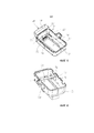
На фиг.6-8 показан другой вариант осуществления, включающий в себя ванну 26, выполненную в виде пластмассовой детали, имеющую поворотную скобу 28, выполненную в виде металлической детали. Поворотная скоба 28 здесь выполнена в виде листовой гнутой в штампе детали и имеет приподнимающие выступы 36, 36' в виде язычков на лапках 32, 32' скобы. На фиг.6 показана поворотная скоба в своем первом положении, а модуль защиты не изображен. На фиг.7, 8 поворотная скоба повернута в свое второе положение, при этом модуль 20 защиты высвобожден с целью его извлечения из ванны 26. Для пояснения положения извлечения модуля этот модуль 20 защиты показан на чертеже на фиг.8.6-8, another embodiment is shown, including a
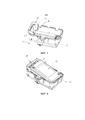
Другой вариант осуществления, включающий в себя ванну 26, выполненную в виде пластмассовой детали, имеющую поворотную скобу 28, выполненную в виде металлической детали, показан на фиг.9, 10. Поворотная скоба 28 имеет приподнимающие выступы 36' в виде лапок на лапках 32, 32' скобы.Another embodiment, including a
Claims (11)
Applications Claiming Priority (3)
| Application Number | Priority Date | Filing Date | Title |
|---|---|---|---|
| DE102013225672.8A DE102013225672A1 (en) | 2013-12-11 | 2013-12-11 | Installation tachograph |
| DE102013225672.8 | 2013-12-11 | ||
| PCT/EP2014/075367 WO2015086300A1 (en) | 2013-12-11 | 2014-11-24 | Built-in tachograph |
Publications (1)
| Publication Number | Publication Date |
|---|---|
| RU2665503C1 true RU2665503C1 (en) | 2018-08-30 |
Family
ID=52011169
Family Applications (1)
| Application Number | Title | Priority Date | Filing Date |
|---|---|---|---|
| RU2016127570A RU2665503C1 (en) | 2013-12-11 | 2014-11-24 | Built-in tachograph |
Country Status (3)
| Country | Link |
|---|---|
| DE (2) | DE102013225672A1 (en) |
| RU (1) | RU2665503C1 (en) |
| WO (1) | WO2015086300A1 (en) |
Citations (4)
| Publication number | Priority date | Publication date | Assignee | Title |
|---|---|---|---|---|
| RU98110577A (en) * | 1996-09-05 | 2000-04-20 | Маннесманн ФДО АГ | TACHOGRAPH WITH EXTENDABLE CONTAINER |
| EP2098831A2 (en) * | 2008-03-06 | 2009-09-09 | TRW Automotive Electronics & Components GmbH | Sensor with holder |
| DE102011079355A1 (en) * | 2011-07-18 | 2013-01-24 | Continental Automotive Gmbh | casing |
| RU2012122547A (en) * | 2011-06-01 | 2013-12-10 | Континенталь Аутомотиве Гмбх | VEHICLE REGISTRATION DEVICE |
Family Cites Families (5)
| Publication number | Priority date | Publication date | Assignee | Title |
|---|---|---|---|---|
| DE19635965A1 (en) * | 1996-09-05 | 1998-03-12 | Mannesmann Vdo Ag | Tachograph with a drawer |
| DE20015100U1 (en) * | 2000-09-01 | 2000-12-21 | Mannesmann VDO AG, 60388 Frankfurt | Tachograph with two read / write units for data cards arranged essentially in one plane |
| US6697719B2 (en) * | 2001-07-19 | 2004-02-24 | Code Alarm, Inc. | Programmable electronic device |
| DE102008061717B4 (en) * | 2008-12-12 | 2011-09-15 | Continental Automotive Gmbh | Tachograph device |
| EP2362357B1 (en) * | 2010-02-22 | 2020-02-12 | Stoneridge Electronics AB | Enhanced functions of a tachograph |
-
2013
- 2013-12-11 DE DE102013225672.8A patent/DE102013225672A1/en not_active Withdrawn
-
2014
- 2014-11-24 RU RU2016127570A patent/RU2665503C1/en active
- 2014-11-24 WO PCT/EP2014/075367 patent/WO2015086300A1/en not_active Ceased
- 2014-11-24 DE DE112014005664.2T patent/DE112014005664A5/en not_active Withdrawn
Patent Citations (4)
| Publication number | Priority date | Publication date | Assignee | Title |
|---|---|---|---|---|
| RU98110577A (en) * | 1996-09-05 | 2000-04-20 | Маннесманн ФДО АГ | TACHOGRAPH WITH EXTENDABLE CONTAINER |
| EP2098831A2 (en) * | 2008-03-06 | 2009-09-09 | TRW Automotive Electronics & Components GmbH | Sensor with holder |
| RU2012122547A (en) * | 2011-06-01 | 2013-12-10 | Континенталь Аутомотиве Гмбх | VEHICLE REGISTRATION DEVICE |
| DE102011079355A1 (en) * | 2011-07-18 | 2013-01-24 | Continental Automotive Gmbh | casing |
Also Published As
| Publication number | Publication date |
|---|---|
| DE102013225672A1 (en) | 2015-06-11 |
| DE112014005664A5 (en) | 2016-09-01 |
| WO2015086300A1 (en) | 2015-06-18 |
Similar Documents
| Publication | Publication Date | Title |
|---|---|---|
| US9882310B2 (en) | Connection structure and apparatus unit | |
| JP4914530B1 (en) | Terminal device | |
| CN108281838A (en) | Cover Member, Cover Unit And Connector | |
| JP2012095930A (en) | Game machine | |
| JP5821470B2 (en) | Game machine | |
| RU2665503C1 (en) | Built-in tachograph | |
| ATE337587T1 (en) | CARD RECEIVING APPARATUS AND METHOD | |
| AU2010202179A1 (en) | Electronic travel book | |
| JP5829642B2 (en) | Electronics | |
| RU2672513C2 (en) | Installation tachograph | |
| JP5848653B2 (en) | Electronic equipment | |
| JP2013214471A (en) | Card unit and card edge connector | |
| JP2008186072A (en) | Read/write device for semiconductor memory card | |
| US8547708B2 (en) | Electronic apparatus | |
| US9979115B2 (en) | Assembly for marking at least one connection of a computer system, connection module and labelling element | |
| CN104600508A (en) | Card connector | |
| JP2010104542A (en) | Control board assembly for game machine | |
| CN101258650B (en) | Housing having an electrical component and an electrical feed line | |
| CN107077627A (en) | Standard Card Reader for Mobile Applications | |
| JP5215214B2 (en) | Card connector device and in-vehicle device | |
| JP4654393B2 (en) | Substrate storage case cover and substrate storage case with cover | |
| JP5474267B1 (en) | Receptacle protective cover and electronic device | |
| JP2006331267A (en) | Electronic apparatus having communication terminal | |
| JP4983184B2 (en) | Case battery holder | |
| JP4978112B2 (en) | Fiscal unit and printer |