RU2689103C1 - Multifunctional automatic digital intelligent well - Google Patents
Multifunctional automatic digital intelligent well Download PDFInfo
- Publication number
- RU2689103C1 RU2689103C1 RU2018116940A RU2018116940A RU2689103C1 RU 2689103 C1 RU2689103 C1 RU 2689103C1 RU 2018116940 A RU2018116940 A RU 2018116940A RU 2018116940 A RU2018116940 A RU 2018116940A RU 2689103 C1 RU2689103 C1 RU 2689103C1
- Authority
- RU
- Russia
- Prior art keywords
- submersible
- control
- well
- multifunctional automatic
- control device
- Prior art date
Links
Images
Classifications
-
- E—FIXED CONSTRUCTIONS
- E21—EARTH OR ROCK DRILLING; MINING
- E21B—EARTH OR ROCK DRILLING; OBTAINING OIL, GAS, WATER, SOLUBLE OR MELTABLE MATERIALS OR A SLURRY OF MINERALS FROM WELLS
- E21B47/00—Survey of boreholes or wells
-
- E—FIXED CONSTRUCTIONS
- E21—EARTH OR ROCK DRILLING; MINING
- E21B—EARTH OR ROCK DRILLING; OBTAINING OIL, GAS, WATER, SOLUBLE OR MELTABLE MATERIALS OR A SLURRY OF MINERALS FROM WELLS
- E21B43/00—Methods or apparatus for obtaining oil, gas, water, soluble or meltable materials or a slurry of minerals from wells
Landscapes
- Life Sciences & Earth Sciences (AREA)
- Engineering & Computer Science (AREA)
- Geology (AREA)
- Mining & Mineral Resources (AREA)
- Physics & Mathematics (AREA)
- Environmental & Geological Engineering (AREA)
- Fluid Mechanics (AREA)
- General Life Sciences & Earth Sciences (AREA)
- Geochemistry & Mineralogy (AREA)
- Geophysics (AREA)
- Structures Of Non-Positive Displacement Pumps (AREA)
- Control Of Non-Positive-Displacement Pumps (AREA)
Abstract
Description
Изобретение относится к области нефтедобычи, в частности к системе управления многофункциональной автоматической цифровой интеллектуальной скважины (МАЦИС) для одновременного управления скоростью ротора погружного электродвигателя (ПЭД) установки центробежного электронасоса (УЭЦН) по данным контроля дебита и параметров скважинной жидкости (СКЖ), прогревом насосно-компрессорных труб (НКТ) для устранения образования асфальто-смолисто-парафиновых отложений (АСПО), индукционным прогревом призабойной зоны пласта для понижения вязкости нефти (природного битума) и/или раздельного выполнения указанных действий и может быть использована на промыслах при добыче нефти из скважин.The invention relates to the field of oil production, in particular to the control system of a multifunctional automatic digital intelligent well (MACIS) for simultaneous control of the rotor speed of a submersible electric motor (SEM) of a centrifugal electric pump (ESP) installation according to the monitoring of flow rate and downhole fluid parameters (SCF), heating the pump compressor pipes (tubing) to eliminate the formation of asphalt-resin-paraffin deposits (ARPD), induction heating of the bottomhole formation zone to reduce the viscosity efti (natural bitumen) and / or separation performance of said action and can be used in the fields in the extraction of oil from wells.
Известна система управления УЭЦН, содержащая станцию управления с преобразователем частоты и контроллерами, систему погружной телеметрии (Станция управления «Электон-05» ПЧ-ТТПТ-800-380-50-1-УХЛ1 ТУ 3416-003-43174012-2001).Known control system ESP, containing the control station with a frequency converter and controllers, a system of submersible telemetry (control station "Electon-05" FC-TTPT-800-380-50-1-UHL1 TU 3416-003-43174012-2001).
Недостатком данной системы является то, что управление ПЭД осуществляется только по предварительно определенному заданию, отсутствует автоматическое регулирование производительности установки в соответствии с изменяющимися условиями добычи нефти, так как при управлении не учитываются реальные динамические характеристики системы «пласт-скважина-УЭЦН».The disadvantage of this system is that the PEM is controlled only according to a predetermined task; there is no automatic control of the plant's performance in accordance with changing oil production conditions, since the management does not take into account the actual dynamic characteristics of the reservoir-ESP system.
Известна система оптимального управления УЭЦН по патенту РФ №88167 от 27.10.2009, авторов Сипайлов В.А., Букреев В.Г. и Сипайлова Н.Ю.The system of optimal control of ESP by the patent of the Russian Federation No. 88167 dated 10.27.2009 by authors Sipailov V.A., Bukreev V.G. and Sipaylova N.Yu.
Полезная модель относится к области управления технологическими процессами в нефтяной промышленности и направлена на повышение качества управления УЭЦН за счет возможности в реальном времени автоматически изменять показатели производительности установки и настраиваться на режим оптимального по технико-экономическим критериям функционирования.The utility model relates to the field of process control in the oil industry and is aimed at improving the quality of control of the ESP system due to the real-time capability to automatically change the plant performance indicators and tune to the mode of optimal operation according to technical and economic criteria.
Указанный технический результат достигается тем, что система оптимального управления УЭЦН, содержащая установленный в скважине погружной электронасосный агрегат с кабельной линией питания его электродвигателя, блок погружной телеметрии с датчиками параметров состояния скважины и электронасосного агрегата, измеритель дебита жидкости, установленный на выкидной линии и подключенный к первому входу блока идентификации, преобразователь частоты, подсоединенный к станции управления, силовой выход которой подключен к кабельной линии питания электродвигателя электронасосного агрегата, а информационный выход станции управления подключен ко второму входу блока идентификации, задатчик режима работы, дополнительно включает блок оптимизации и датчик буферного давления, выход которого соединен с первым входом блока оптимизации и третьим входом блока идентификации, четвертый вход которого подключен к первому выходу задатчика режима работы, второй выход которого подключен к информационному входу станции управления, третий выход соединен со вторым входом блока оптимизации, третий вход которого подключен к выходу блока идентификации, выход блока оптимизации подключен к управляющему входу преобразователя частоты.This technical result is achieved by the fact that the system of optimal control of the ESP unit containing a submersible electric pump unit installed in a well with a cable supplying its electric motor, a submersible telemetry unit with sensors for well status parameters and an electropump unit, a liquid flow meter installed on the flow line and connected to the first one the input of the identification block, a frequency converter connected to the control station, the power output of which is connected to the cable supply line and the information output of the control station is connected to the second input of the identification unit, the operating mode setter, additionally includes an optimization unit and a buffer pressure sensor, the output of which is connected to the first input of the optimization unit and the third input of the identification unit, the fourth input of which is connected to the first the output of the unit mode of operation, the second output of which is connected to the information input of the control station, the third output is connected to the second input of the optimization block, the third input of which is connected to the output of the identification block, the output of the optimization block is connected to the control input of the frequency converter.
Основные показатели работы УЭЦН - производительность (дебит жидкости) и потребление электроэнергии - зависят от технических параметров насоса и трубопровода, частоты вращения ротора электродвигателя, а также пластового и буферного давлений. Управление режимом работы УЭЦН обеспечивается путем изменения производительности (дебита жидкости) электроцентробежного насоса за счет регулирования частоты вращения ротора электродвигателя электронасосного агрегата путем изменения частоты напряжения и величины напряжения на выходе преобразователя частоты и напряжения (ПНЧ) в соответствии с рассчитанными в блоке оптимизации значениями, определяющими оптимальное по технико-экономическим критериям функционирование УЭЦН.The key performance indicators of the ESP system — capacity (flow rate) and energy consumption — depend on the technical parameters of the pump and pipeline, the rotor speed of the electric motor, and the formation and buffer pressures. The operation of the ESP unit is controlled by changing the performance (flow rate) of an electric centrifugal pump by controlling the rotor speed of the electric motor of the electric pump unit by changing the voltage frequency and the output voltage of the frequency converter and voltage (FNP) in accordance with the optimum values calculated in the optimization unit on the technical and economic criteria for the operation of ESP.
Оптимизация реализуется с помощью модели объекта методом перебора полученных решений в пределах заданных технологических ограничений. Результатом работы блока оптимизации является расчет управляющих воздействий (напряжение и частота напряжения на выходе преобразователя частоты), определяющих минимальное отклонение показателя технико-экономической эффективности УЭЦН (коэффициент рентабельности по электроэнергии) от планового значения. Оптимальные значения управляющих воздействий (частота напряжения и величина напряжения с выхода ПНЧ передаются в станцию управления. В результате ее работы происходит изменение частоты вращения ротора электродвигателя и устанавливается режим работы установки, наиболее приближенный к оптимальному. Задатчик режима работы может быть реализован в виде автоматизированного рабочего места технолога, а блоки идентификации и оптимизации программным (цифровым) способом с помощью программируемых контроллеров, например, контроллеров станции управления и преобразователя частоты.Optimization is implemented using an object model by iterating over the solutions obtained within the specified technological constraints. The result of the work of the optimization unit is the calculation of control actions (voltage and frequency of the voltage at the output of the frequency converter), which determine the minimum deviation of the technical and economic efficiency of the ESP (profitability ratio for electricity) from the planned value. Optimal values of control actions (voltage frequency and voltage value from the output of the FNP are transmitted to the control station. As a result of its operation, the rotor speed of the electric motor is changed and the installation mode is set to be closest to the optimum. The operating mode setpoint can be implemented as an automated workplace technologist, and the identification and optimization units by software (digital) method using programmable controllers, for example, station controllers the board and the inverter.
Недостатком известной системы является недостаточный набор параметров управления УЭЦН и СКЖ, по которым производится оптимизация работы скважины и недостаточный набор функций для многофункциональности автоматической комплексной станции интеллектуальной скважины.A disadvantage of the known system is the insufficient set of control parameters of the ESP and SCW, which are used to optimize the operation of the well and the insufficient set of functions for the multifunctionality of the automatic integrated station of the intellectual well.
Последний недостаток аналога для управления УЭЦН при добыче высоковязких нефтей устраняется в многофункциональной автоматической комплексной станции интеллектуальной скважины по патенту РФ №128894 от 10.06.2013, авторов Глебова В.И., Скворцова Д.Е., принятой за прототип.The last drawback of the analogue for the control of ESP in the production of highly viscous oils is eliminated in the multifunctional automatic complex station of the intellectual well according to the patent of Russian Federation №128894 from 10.06.2013, the authors Glebov VI, Skvortsova D.Е.
Система состоит из погружной установки электроцентробежного насоса (УЭЦН) с погружным электродвигателем (ПЭД), погружной греющей кабельной линии, электрической линии связи и наземного оборудования, состоящего из управляющего устройства ПЭД и кабельным нагревом (КН), высокочастотного генератора с возможностью передачи энергии до облучающего индуктора на расстоянии более 1000 м от генератора.The system consists of a submersible installation of an electrical centrifugal pump (ESP) with a submersible electric motor (SEM), a submersible heating cable line, an electrical communication line and ground equipment consisting of an SEM control device and cable heating (KN), a high-frequency generator with the ability to transfer energy to the irradiator inductor at a distance of more than 1000 m from the generator.
Технический результат, достигаемый системой-прототипом, заключается в обеспечения комплексной работы одной станции для одновременного или раздельного управляемого процесса работы насосного оборудования, прогрева НКТ, индукционного прогрева призабойной зоны пласта и/или трубопроводов, с возможностью архивирования данных о работе каждого из процессов, дистанционного управления и передачи данных о работе каждого из процессов по беспроводному и/или проводному каналу, а также увеличение периода наработки на отказ скважинного оборудования за счет обеспечения увеличения надежности работы, снижению времени и трудозатрат при монтаже и эксплуатации многофункциональной автоматической комплексной станцией интеллектуальной скважины. Благодаря тому, что система-прототип выполнена в одном корпусе, это позволяет доставить станцию в сборе и компактно разместить станцию на месте эксплуатации, что снижает трудозатраты на сборку и запуск в эксплуатацию, по сравнению с прототипом.The technical result achieved by the prototype system is to ensure the integrated work of one station for simultaneous or separate controlled process of pumping equipment operation, heating the tubing, induction heating of the bottomhole formation zone and / or pipelines, with the ability to archive data on the operation of each of the processes, remote control and transmitting data on the operation of each of the processes wirelessly and / or wired channel, as well as an increase in the time between failures of the well equipment tions by providing increase reliability, reduce time and labor for installation and operation of automatic intelligent well multifunction integrated station. Due to the fact that the prototype system is made in the same package, this makes it possible to deliver the assembled station and compactly place the station at the place of operation, which reduces the labor costs for assembling and launching into operation, as compared to the prototype.
Станция имеет дополнительно установленную систему дозированной подачи реагента и индукционного прогрева призабойной зоны пласта и/или трубопроводов и имеет возможность обеспечивать полный процесс оптимизации и интенсификации добычи, путем обеспечения оптимального режима работы насосного оборудования за счет ликвидации АСПО и солеотложений на скважинном оборудовании и предотвращения увеличения вязкости флюида при подъеме по НКТ.The station has an additionally installed system for metering reagent and induction heating of the bottomhole formation zone and / or pipelines and has the ability to provide a complete process of optimization and intensification of production by ensuring optimal operation of pumping equipment by eliminating ARP and scaling at the well equipment and preventing an increase in fluid viscosity when lifting the tubing.
Благодаря вышеуказанному исключается возможность образования АСПО и солеотложений на погружном скважинном оборудовании, упрощается процесс монтажа, эксплуатации и обслуживания станции, увеличивается период наработки оборудования на отказ по сравнению с известным устройством по прототипу.Due to the above, the possibility of formation of paraffin and scaling on submersible borehole equipment is eliminated, the installation, operation and maintenance of the station is simplified, the equipment-to-failure time is increased compared to the known prototype device.
При эксплуатации проблемных скважин, осложненных АСПО, необходимо производить прогрев призабойной зоны пласта без подъема пластовой жидкости (например, при подготовке скважины к запуску для того, чтобы вследствие нагрева снизить вязкость жидкости и обеспечить более мягкие условия для работы ПЭД) или осуществлять индукционный нагрев совместно с питанием ПЭД и прогревом НКТ, когда скважина уже вышла на режим и необходимо поддерживать стационарное тепловое поле ствола скважин. Или производить только питание ПЭД и дозированную подачу реагента, когда параметры добычи позволяют производить на каком-то отрезке времени подъем жидкости без нагрева, а при отключении ПЭД можно оставить нагрев скважины и дозированную подачу реагента в работе (такая ситуация возникает при работе скважины с периодическим режимом работы по откачке жидкости). Таким образом, без переналадки установки, в автоматическом режиме, без подъема узлов из ствола скважины обеспечивается расширение ее функциональных и технологических возможностей. Все указанные операции возможно производить и одновременно в осложненных АСПО и солеотложениями скважинах.During operation of problematic wells complicated by ARPD, it is necessary to warm up the bottomhole formation zone without raising the formation fluid (for example, when preparing a well for launch, to reduce the viscosity of the fluid due to heating and to provide milder conditions for the operation of the SEM) or to perform induction heating together with powering the SEM and heating the tubing, when the well has already entered the mode and it is necessary to maintain a stationary thermal field of the wellbore. Or to produce only the power supply of the SEM and the dosed supply of the reagent, when the production parameters allow to produce the liquid without heating for a certain period of time, and when the SEM is disconnected, it is possible to leave the well heated and the dosed supply of the reagent in operation (this situation occurs when the well is operated with a periodic mode Work on the pumping fluid). Thus, without readjusting the installation, in automatic mode, without lifting nodes from the wellbore, its functional and technological capabilities are expanded. All of these operations may be performed simultaneously in the complicated ARP and scaling wells.
Недостатками прототипа является недостаточный набор параметров управления УЭЦН и СКЖ, по которым производится оптимизация работы скважины и отсутствие прибора для измерения расхода скважинной жидкости, по данным которого осуществляется измерение дебита ИС; отсутствие измерителей концентрации воды, плотности и вязкости, по которым определяется момент на валу ПЭД и регулируется частота ротора двигателя, отсутствие преобразователя частоты ПЭД.The disadvantages of the prototype is the lack of a set of control parameters ESP and SKZH, which is the optimization of the well and the absence of a device for measuring the flow rate of the well fluid, according to which the measurement of the flow rate of the IP; the lack of water concentration, density and viscosity meters, which determine the moment on the shaft of the SEM and regulates the frequency of the rotor of the engine, the absence of the SEM frequency converter.
Данные недостатки аналогов и прототипа могут быть устранены в предлагаемой нами многофункциональной автоматической цифровой интеллектуальной скважине (МАЦИС) с использованием ПМР-анализатора (ПМРА) и преобразователя напряжения и частоты (ПНЧ) в наземном оборудовании.These drawbacks of the analogs and the prototype can be eliminated in our multifunctional automatic digital intelligent well (MACIS) using a PMR analyzer (PMRA) and a voltage and frequency converter in the surface equipment.
Технический результат предлагаемого изобретения заключается в расширении функциональных возможностей в заявляемой МАЦИС за счет дополнительного использования ПМРА и ПНЧ.The technical result of the invention is to expand the functionality of the claimed MACIS due to the additional use of PMRA and the FLL.
Технический результат достигается тем, что в многофункциональной автоматической цифровой интеллектуальной скважине, включающей погружное оборудование, состоящее из погружного центробежного насоса с погружным электродвигателем, погружной греющей кабельной линии, электрической линии связи с системой погружной телеметрии, высокочастотного генератора с возможностью передачи энергии до индуктора и станцию наземного оборудования, включающую управляющее устройство, соединенное через входы и выходы с наземным и погружным оборудованием и возможностью управления погружным электродвигателем, модуль беспроводной и/или проводной связи с возможностью управления, приема и передачи данных по средствам беспроводной и/или проводной связи, насос-дозатор, манометр, уровнемер с возможностью передачи информации на управляющее устройство, расходомер реагента с возможностью передачи данных о расходе реагента на управляющее устройство, согласно настоящему изобретению, скважина дополнительно снабжена устьевым модулем (УМ), имеющим подвижный патрубок и выкидной патрубок в магистральный трубопровод, а наземное оборудование снабжено преобразователем напряжения/частоты и проточным экспресс-анализатором протонного магнитного резонанса (ПМРА), включающим магнит, диэлектрическую трубку с намотанной на нее катушкой индуктивности датчика ПМР, выход которой высокочастотным кабелем длиной в четверть волны соединен с усилителем мощности радиочастотных импульсов (передатчиком) и усилителем полезных сигналов ПМР (приемником) релаксометра, с которого через модуль информация о многофункциональной автоматической комплексной системе «интеллектуальная скважина - протонный магнитно-резонансный анализатор» передается на диспетчерский пульт контроля и управления нефтепромыслом.The technical result is achieved in that in a multi-functional automatic digital intellectual well, including a submersible equipment consisting of a submersible centrifugal pump with a submersible electric motor, a submersible heating cable line, an electrical communication line with a submersible telemetry system, a high-frequency generator with the ability to transfer energy to the inductor and a ground station equipment, including a control device connected via inputs and outputs with ground and submersible equipment and the ability to control the submersible motor, wireless and / or wired communication module with the ability to control, receive and transmit data by means of wireless and / or wired communication, metering pump, pressure gauge, level gauge with information transfer capability to the control device, reagent flow meter with transmission capability data on the flow of reagent to the control device according to the present invention, the well is additionally equipped with a wellhead module (PA), which has a movable port and a discharge pipe to the master The piping and ground equipment is equipped with a voltage / frequency converter and a flow proton magnetic resonance analyzer (PMRA), which includes a magnet, a dielectric tube with an PMR sensor inductance wound around it, the output of which is connected to a radio frequency power amplifier with a high-frequency cable pulses (transmitter) and amplifier useful signals PMR (receiver) relaxometer, from which through the module information about the multi-functional automatic complex th system "intellectual well - proton magnetic resonance analyzer" is transmitted to the control room monitoring and control oil production has.
При этом УМ выполнен в виде расширяющегося конического участка трубы; проточный ПМРА используется для измерения производительности скважины и для измерения физико-химических параметров скважинной жидкости.While the MIND is made in the form of an expanding conical pipe section; flow-through PMRA is used to measure well performance and to measure the physicochemical parameters of the well fluid.
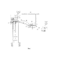
Сущность изобретения поясняется чертежом, где на фиг. 1 представлена схема реализации заявляемой системы.The invention is illustrated in the drawing, where in FIG. 1 shows the implementation scheme of the inventive system.
Обозначения на чертеже:Designations in the drawing:
1 - скважина;1 - well;
2 - УЭЦН;2 - ESP;
3 - ПЭД;3 - SEM;
4 - погружная греющая кабельная линии;4 - immersion heating cable lines;
5 - линия связи с системой погружной телеметрии,5 - communication line with the submersible telemetry system,
6 - высокочастотный генератор6 - high frequency generator
7 - индуктор,7 - inductor
8 - станция наземного оборудования,8 - ground equipment station
9 - управляющее устройство9 - control device
10 - модуль управления,10 - control module
11 - насос-дозатор11 - dosing pump
12 - манометр12 - manometer
13 - уровнемер13 - level gauge
14 - расходомер14 - flow meter
15 - преобразователь напряжения/частоты,15 - voltage / frequency converter,
16 - устьевой модуль;16 — wellhead module;
17 - подвижный патрубок17 - movable pipe
18 - выкидной патрубок18 - discharge pipe
19 - магистральный трубопровод19 - the main pipeline
20 - проточный экспресс-анализатор протонного магнитного резонанса20 - flow-through rapid analyzer of proton magnetic resonance
21 - магнит,21 - magnet
22 - диэлектрическая трубка22 - dielectric tube
23 - катушка датчика ПМР,23 - coil sensor PMR,
24 - ВЧ-кабель длиной в четверть волны,24 is a quarter-wave RF cable,
25 - усилитель мощности радиочастотных импульсов (передатчик,25 - power amplifier radio frequency pulses (transmitter,
26 - усилитель полезных сигналов ПМР (приемник),26 - amplifier useful signal PMR (receiver),
27 - релаксометр27 - relaxometer
28 - диспетчерский пульт контроля и управления нефтепромыслом.28 - dispatching control and control of oilfield.
МАЦИС 1 включает погружное оборудование, состоящее из центробежного насоса 2 с погружным электродвигателем 3, погружной греющей кабельной линии 4 насосно-компрессорных труб, электрической линии связи 5 с системой погружной телеметрии, высокочастотного генератора 6 с возможностью передачи энергии до индуктора 7, размещенного на расстояние более 1000 м и станции наземного оборудования 8, включающей управляющее устройство 9, соединенное через входы и выходы с наземным и погружным оборудованием с возможностью управления ПЭД, модуль 10 беспроводной и/или проводной связи с возможностью управления, приема и передачи данных по средствам беспроводной и/или проводной связи (на фиг. 1 не показаны), насос-дозатор 11, манометр 12, уровнемер 13 с возможностью передачи информации на управляющее устройство 9, расходомер 14 реагента с возможностью передачи данных о расходе реагента на управляющее устройство, в которой согласно изобретению скважина дополнительно снабжена преобразователем напряжения/частоты 15 для управления скоростью ротора погружного электродвигателя 3 УЭЦН 2 и устьевым модулем (УМ) 16, имеющий подвижный патрубок 17 для отбора пробы из УМ и выкидной патрубок 18 для выброса СКЖ в магистральный трубопровод 19, а наземное оборудование имеет проточный экспресс-анализатор протонного магнитного резонанса (ПМРА) 20, включающий в своем составе магнит 21, в межполюсном пространстве которого проходит диэлектрическая трубка 22 с намотанной на нее катушкой 23 датчика ПМР, выход которой четвертьволновой (λ/4 = c/4νo=3⋅108/4⋅6⋅10, где с - скорость света, νo=6⋅106 МГц - резонансная частота ПМР-релаксометра ПМРА) кабелем 24, соединен с усилителем мощности 25 радиочастотных импульсов (передатчиком) и усилителем полезных сигналов ПМР (приемником) 26 релаксометра 27, через модуль 10 передающим информацию о МАКСИС-ПМРА на диспетчерский пульт 28 контроля и управления нефтепромыслом.MATIS 1 includes a submersible equipment consisting of a
МАЦИС 1 функционирует следующим образом: центробежный насос 2 с погружным электродвигателем 3 откачивает скважинную жидкость вязкой нефти, у которой снижена вязкость после ее прогрева погружной греющей кабельной линией 4, высокочастотным генератором 6 посредством передачи энергии от индуктора 7 в затрубное пространство; в станции наземного оборудования 8, включающей управляющее устройство 9, соединенное через входы и выходы с наземным и погружным оборудованием с возможностью управления ПЭД через модуль управления 10 УЭЦН+ПЭД, насосом-дозатором 11, контролем манометром 12, уровнемером 13 расходомером 14 осуществляется подача реагента с возможностью передачи данных о расходе реагента на управляющее устройство, в которой согласно изобретению скважина дополнительно снабжена преобразователем напряжения/частоты 15 для управления в зависимости от параметров скважины и ФХП СКЖ скоростью ротора погружного электродвигателя 3 УЭЦН 2. В устьевом модуле 16 подвижный патрубок 17 осуществляет отбор пробы в любом сечении УМ, посредством выкидных патрубков 18 часть СКЖ выталкивается в магистральный трубопровод 19, а часть пробы через подвижный патрубок 17 поступает в проточный экспресс-анализатор протонного магнитного резонанса (ПМРА) 20, а именно в диэлектрическую трубку 22 с намотанной на нее катушкой 23 в межполюсном пространстве магнита 21 датчика ПМР, сигнал ПМР с которой через четвертьволновой кабель 24 подается в усилитель полезных сигналов ПМР (приемник) 26 релаксометра 27 и далее через модуль 10 информация о параметрах МАЦИС и о физико-химических параметрах СКЖ по ГОСТ Р 8.615-2005 ГСИ передается на диспетчерский пульт 28 контроля и управления нефтепромыслом.MATSIS 1 operates as follows: a
Выполненные модельные эксперименты на стенде и моделирование процесса управления дебитом скважины показали пригодность системы МАЦИС-ПМРА для решения задач оптимизации работы интеллектуальной скважины.The performed model experiments on the bench and modeling of the flow rate control process showed the suitability of the MACIS-PMRA system for solving problems of optimizing the operation of an intelligent well.
Claims (4)
Priority Applications (1)
| Application Number | Priority Date | Filing Date | Title |
|---|---|---|---|
| RU2018116940A RU2689103C1 (en) | 2018-05-07 | 2018-05-07 | Multifunctional automatic digital intelligent well |
Applications Claiming Priority (1)
| Application Number | Priority Date | Filing Date | Title |
|---|---|---|---|
| RU2018116940A RU2689103C1 (en) | 2018-05-07 | 2018-05-07 | Multifunctional automatic digital intelligent well |
Publications (1)
| Publication Number | Publication Date |
|---|---|
| RU2689103C1 true RU2689103C1 (en) | 2019-05-23 |
Family
ID=66637080
Family Applications (1)
| Application Number | Title | Priority Date | Filing Date |
|---|---|---|---|
| RU2018116940A RU2689103C1 (en) | 2018-05-07 | 2018-05-07 | Multifunctional automatic digital intelligent well |
Country Status (1)
| Country | Link |
|---|---|
| RU (1) | RU2689103C1 (en) |
Cited By (3)
| Publication number | Priority date | Publication date | Assignee | Title |
|---|---|---|---|---|
| CN113992710A (en) * | 2021-10-18 | 2022-01-28 | 三一石油智能装备有限公司 | Distributed control system and control method for continuous oil pipe equipment |
| CN115853002A (en) * | 2022-11-29 | 2023-03-28 | 中国建筑第八工程局有限公司 | A multi-stage linkage self-activating intelligent foundation pit lowering and drainage system |
| RU2796088C1 (en) * | 2022-03-21 | 2023-05-16 | Альберт Ринатович Ахметгалиев | Method for control of parameters of liquids poured into a well |
Citations (7)
| Publication number | Priority date | Publication date | Assignee | Title |
|---|---|---|---|---|
| US5012868A (en) * | 1989-03-14 | 1991-05-07 | Uentech Corporation | Corrosion inhibition method and apparatus for downhole electrical heating in mineral fluid wells |
| WO1992021880A1 (en) * | 1990-01-10 | 1992-12-10 | Escue Research And Development Company | Pump control system for a downhole motor-pump assembly and method of using same |
| WO2001065055A1 (en) * | 2000-03-02 | 2001-09-07 | Shell Internationale Research Maatschappij B.V. | Controlled downhole chemical injection |
| RU67719U1 (en) * | 2007-06-25 | 2007-10-27 | Рустем Султанхамитович Кашаев | PORTABLE RELAXOMETER OF NUCLEAR MAGNETIC RESONANCE |
| RU111190U1 (en) * | 2010-03-15 | 2011-12-10 | Владимир Анатольевич Иванов | OIL PRODUCING WELL WITH ARTIFICIAL INTELLIGENCE |
| RU128894U1 (en) * | 2012-12-07 | 2013-06-10 | Общество с ограниченной ответственностью "Макс Инжиниринг" | MULTIFUNCTIONAL AUTOMATIC COMPLEX STATION OF INTELLECTUAL WELL |
| RU2568448C1 (en) * | 2014-11-06 | 2015-11-20 | Общество с ограниченной ответственностью "Научно-производственная фирма Завод "Измерон" | Smart gas and gas condensate well and method of its rigging-up |
-
2018
- 2018-05-07 RU RU2018116940A patent/RU2689103C1/en not_active IP Right Cessation
Patent Citations (7)
| Publication number | Priority date | Publication date | Assignee | Title |
|---|---|---|---|---|
| US5012868A (en) * | 1989-03-14 | 1991-05-07 | Uentech Corporation | Corrosion inhibition method and apparatus for downhole electrical heating in mineral fluid wells |
| WO1992021880A1 (en) * | 1990-01-10 | 1992-12-10 | Escue Research And Development Company | Pump control system for a downhole motor-pump assembly and method of using same |
| WO2001065055A1 (en) * | 2000-03-02 | 2001-09-07 | Shell Internationale Research Maatschappij B.V. | Controlled downhole chemical injection |
| RU67719U1 (en) * | 2007-06-25 | 2007-10-27 | Рустем Султанхамитович Кашаев | PORTABLE RELAXOMETER OF NUCLEAR MAGNETIC RESONANCE |
| RU111190U1 (en) * | 2010-03-15 | 2011-12-10 | Владимир Анатольевич Иванов | OIL PRODUCING WELL WITH ARTIFICIAL INTELLIGENCE |
| RU128894U1 (en) * | 2012-12-07 | 2013-06-10 | Общество с ограниченной ответственностью "Макс Инжиниринг" | MULTIFUNCTIONAL AUTOMATIC COMPLEX STATION OF INTELLECTUAL WELL |
| RU2568448C1 (en) * | 2014-11-06 | 2015-11-20 | Общество с ограниченной ответственностью "Научно-производственная фирма Завод "Измерон" | Smart gas and gas condensate well and method of its rigging-up |
Cited By (4)
| Publication number | Priority date | Publication date | Assignee | Title |
|---|---|---|---|---|
| CN113992710A (en) * | 2021-10-18 | 2022-01-28 | 三一石油智能装备有限公司 | Distributed control system and control method for continuous oil pipe equipment |
| CN113992710B (en) * | 2021-10-18 | 2024-05-28 | 三一石油智能装备有限公司 | Distributed control system and control method for coiled tubing equipment |
| RU2796088C1 (en) * | 2022-03-21 | 2023-05-16 | Альберт Ринатович Ахметгалиев | Method for control of parameters of liquids poured into a well |
| CN115853002A (en) * | 2022-11-29 | 2023-03-28 | 中国建筑第八工程局有限公司 | A multi-stage linkage self-activating intelligent foundation pit lowering and drainage system |
Similar Documents
| Publication | Publication Date | Title |
|---|---|---|
| EP0558534B1 (en) | Well completion system | |
| RU2385409C2 (en) | Method of extracting fluid from reservoir of one well with electric drive pump equipped with electric valve and installation for implementation of this method | |
| CN102305998B (en) | Closed-loop control method and system for pumping unit based on downhole multi-parameter real-time monitoring | |
| RU2512228C1 (en) | Plant for dual operation of multiple-zone well with telemetry system | |
| RU2341647C1 (en) | Method of dataware and control of fluid withdrawal from oil wells and facility for implementation of this method | |
| MX2012011720A (en) | System and method for subsea production system control. | |
| RU2689103C1 (en) | Multifunctional automatic digital intelligent well | |
| RU111190U1 (en) | OIL PRODUCING WELL WITH ARTIFICIAL INTELLIGENCE | |
| RU2014129153A (en) | VALVE PUMPING UNIT FOR SIMULTANEOUS-SEPARATE OPERATION OF A MULTI-PLASTIC WELL | |
| RU2637245C1 (en) | System for automatic feed of inhibitor of hydrate formation into lines of gas field | |
| US20180003180A1 (en) | Pumping energy management control system | |
| CN104563985B (en) | A digital dispensing test deployment system and method | |
| RU2552555C1 (en) | Method of simultaneous separate or successive production of reservoir fluid from well of multipay fields with preliminary installation of packers | |
| US9920603B2 (en) | Method of operating a well using a pump assembly with a variable-frequency drive | |
| CN115434693B (en) | A device and method for measuring and removing wellbore hydrate blockage position | |
| RU89604U1 (en) | DEVICE FOR SIMULTANEOUSLY SEPARATE OPERATION OF MULTI-PLASTIC WELLS | |
| CN115992695B (en) | Novel underground intelligent measurement and control device, system and method | |
| CN107355214B (en) | Oil-submersible linear motor reciprocating pump closed-loop control system | |
| CN202273839U (en) | Intelligent oil-gas mixing conveying system with remote monitoring | |
| WO2016040220A1 (en) | Bottom hole injection with pump | |
| RU2440488C2 (en) | Method of simultaneous separate operation of multiple-zone wells and device for its implementation | |
| RU2693119C1 (en) | Submersible pumping unit | |
| CN208010703U (en) | Hydraulic petroleum lifting device intelligence control system | |
| RU2546218C1 (en) | Producing reservoirs survey method at dual operation of multi-pay well and installation for its implementation | |
| CN203882203U (en) | Constant-flow control device of unsteady flow water pumping test |
Legal Events
| Date | Code | Title | Description |
|---|---|---|---|
| MM4A | The patent is invalid due to non-payment of fees |
Effective date: 20200508 |