RU2727103C2 - Electric jet propulsion plant - Google Patents
Electric jet propulsion plant Download PDFInfo
- Publication number
- RU2727103C2 RU2727103C2 RU2018134660A RU2018134660A RU2727103C2 RU 2727103 C2 RU2727103 C2 RU 2727103C2 RU 2018134660 A RU2018134660 A RU 2018134660A RU 2018134660 A RU2018134660 A RU 2018134660A RU 2727103 C2 RU2727103 C2 RU 2727103C2
- Authority
- RU
- Russia
- Prior art keywords
- chamber
- frequency
- housing
- injection device
- electrodes
- Prior art date
Links
- 238000002347 injection Methods 0.000 claims abstract description 13
- 239000007924 injection Substances 0.000 claims abstract description 13
- 238000010438 heat treatment Methods 0.000 claims abstract description 10
- 239000000446 fuel Substances 0.000 claims abstract description 9
- TWNQGVIAIRXVLR-UHFFFAOYSA-N oxo(oxoalumanyloxy)alumane Chemical compound O=[Al]O[Al]=O TWNQGVIAIRXVLR-UHFFFAOYSA-N 0.000 claims description 2
- 230000000694 effects Effects 0.000 abstract description 3
- 238000004804 winding Methods 0.000 abstract description 3
- PNEYBMLMFCGWSK-UHFFFAOYSA-N Alumina Chemical compound [O-2].[O-2].[O-2].[Al+3].[Al+3] PNEYBMLMFCGWSK-UHFFFAOYSA-N 0.000 abstract 3
- 239000000126 substance Substances 0.000 abstract 1
- 239000012530 fluid Substances 0.000 description 11
- 238000005265 energy consumption Methods 0.000 description 3
- 239000007789 gas Substances 0.000 description 3
- 230000001133 acceleration Effects 0.000 description 2
- 238000002485 combustion reaction Methods 0.000 description 2
- 239000002828 fuel tank Substances 0.000 description 2
- VNWKTOKETHGBQD-UHFFFAOYSA-N methane Chemical compound C VNWKTOKETHGBQD-UHFFFAOYSA-N 0.000 description 2
- 239000007800 oxidant agent Substances 0.000 description 2
- 239000003380 propellant Substances 0.000 description 2
- 230000015556 catabolic process Effects 0.000 description 1
- 238000010586 diagram Methods 0.000 description 1
- 230000005672 electromagnetic field Effects 0.000 description 1
- 230000005281 excited state Effects 0.000 description 1
- 230000005484 gravity Effects 0.000 description 1
- 238000003306 harvesting Methods 0.000 description 1
- 229930195733 hydrocarbon Natural products 0.000 description 1
- 150000002430 hydrocarbons Chemical class 0.000 description 1
- 239000003350 kerosene Substances 0.000 description 1
- 239000007788 liquid Substances 0.000 description 1
- 238000000034 method Methods 0.000 description 1
- 239000000203 mixture Substances 0.000 description 1
- 238000005728 strengthening Methods 0.000 description 1
- XLYOFNOQVPJJNP-UHFFFAOYSA-N water Chemical compound O XLYOFNOQVPJJNP-UHFFFAOYSA-N 0.000 description 1
Images
Classifications
-
- F—MECHANICAL ENGINEERING; LIGHTING; HEATING; WEAPONS; BLASTING
- F03—MACHINES OR ENGINES FOR LIQUIDS; WIND, SPRING, OR WEIGHT MOTORS; PRODUCING MECHANICAL POWER OR A REACTIVE PROPULSIVE THRUST, NOT OTHERWISE PROVIDED FOR
- F03H—PRODUCING A REACTIVE PROPULSIVE THRUST, NOT OTHERWISE PROVIDED FOR
- F03H1/00—Using plasma to produce a reactive propulsive thrust
Landscapes
- Engineering & Computer Science (AREA)
- Chemical & Material Sciences (AREA)
- Combustion & Propulsion (AREA)
- Physics & Mathematics (AREA)
- Plasma & Fusion (AREA)
- Mechanical Engineering (AREA)
- General Engineering & Computer Science (AREA)
- Combustion Methods Of Internal-Combustion Engines (AREA)
Abstract
Description
Изобретение относится к области реактивных двигательных установок космических и низкоорбитальных летательных аппаратов с низкой энерговооруженностью.The invention relates to the field of jet propulsion systems for space and low-orbit aircraft with low power-to-weight ratio.
Известна электроракетная двигательная установка [1, 2], содержащая следующие элементы: впускное устройство, компрессор и охладитель, дуговой нагреватель, МГД - ускоритель, топливный танк и трубопроводы, источник энергии, корпус-радиатор.Known electric rocket propulsion system [1, 2], containing the following elements: inlet device, compressor and cooler, arc heater, MHD - accelerator, fuel tank and pipelines, energy source, housing-radiator.
Наиболее близким к заявляемому устройству является прямоточная электрореактивная двигательная установка [3], включающая в себя: корпус, диффузор, расположенный в передней части корпуса, камеру нагрева с высокочастотными электродами и сопло, соединенное каналом с камерой нагрева, причем она снабжен высокочастотной обмоткой, которая подключена к высокочастотному генератору и расположена вокруг указанной камеры нагрева, а также анодом, катодом и катушкой в виде соленоида, предназначенной для создания в указанном канале асимметричного магнитного поля для дополнительного ускорения выходящего из сопла воздуха.The closest to the claimed device is a direct-flow electric propulsion system [3], which includes: a housing, a diffuser located in the front of the housing, a heating chamber with high-frequency electrodes and a nozzle connected by a channel to the heating chamber, and it is equipped with a high-frequency winding, which is connected to the high-frequency generator and is located around the specified heating chamber, as well as an anode, a cathode and a coil in the form of a solenoid, designed to create an asymmetric magnetic field in the specified channel to further accelerate the air leaving the nozzle.
Недостатком указанного устройства является низкий КПД двигательной установки и высокие энергозатраты на ионизацию, ускорение потока, создание асимметричного магнитного поля. Все указанные факторы при ограниченной мощности ЭРДУ отрицательно сказываются на величине удельного импульса электроракетной двигательной установки и приводят к снижению ее КПД.The disadvantage of this device is the low efficiency of the propulsion system and high energy consumption for ionization, flow acceleration, and the creation of an asymmetric magnetic field. All of these factors with a limited power of the EPP have a negative effect on the specific impulse of the electric propulsion system and lead to a decrease in its efficiency.
Техническим результатом изобретения является повышение КПД и удельного импульса электрореактивной двигательной установки.The technical result of the invention is to increase the efficiency and specific impulse of the electric propulsion system.
Указанная цель достигается тем, что в известной электрореактивной двигательной установке, содержащейThis goal is achieved by the fact that in the known electric propulsion system containing
корпус, диффузор, расположенный в передней части корпуса, камеру нагрева с высокочастотными электродами и сопло, соединенное каналом с камерой нагрева, причем она снабжен высокочастотной обмоткой в виде соленоида, которая подключена к высокочастотному генератору и расположена вокруг указанной камеры нагрева, дополнительноhousing, a diffuser located in the front of the housing, a heating chamber with high-frequency electrodes and a nozzle connected by a channel to the heating chamber, and it is equipped with a high-frequency coil in the form of a solenoid, which is connected to a high-frequency generator and is located around said heating chamber, additionally
электрореактивная двигательная установка снабжена высоковольтным высокочастотным источником тока, на входе в тепловой камере после диффузора дополнительно расположены коаксиально электроды, выполненные в виде полых цилиндров, и соединены каждый с одним из электрических выводов высоковольтного высокочастотного источника тока, при этом устройство впрыска горючего выполнено в виде двух частей, первая из которых расположена непосредственно за коаксиальными цилиндрическими электродами, а вторая часть устройства впрыска распределена вдоль оставшейся области тепловой камеры по оси потока, при этом соленоид располагается снаружи тепловой камеры над ее областью, в которой расположена вторая часть устройства впрыска, при этом корпус и тепловая камера выполнены из диэлектрика, например оксида алюминия.the electric propulsion system is equipped with a high-voltage high-frequency current source, at the entrance to the thermal chamber after the diffuser, electrodes made in the form of hollow cylinders are additionally located coaxially, and each is connected to one of the electrical terminals of the high-voltage high-frequency current source, while the fuel injection device is made in the form of two parts , the first of which is located directly behind the coaxial cylindrical electrodes, and the second part of the injection device is distributed along the remaining area of the thermal chamber along the flow axis, while the solenoid is located outside the thermal chamber above its area in which the second part of the injection device is located, while the housing and the thermal the chamber is made of a dielectric, such as aluminum oxide.
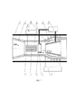
На фиг. 1 изображена схема электрореактивной двигательной установки.In FIG. 1 shows a diagram of an electric propulsion system.
Диэлектрический корпус 1 имеет диффузор - воздухозаборник 2, за которым в корпусе располагаются коаксиальные электроды 3, 4. За ними по оси двигателя располагается устройство впрыска горючего 5, 6. Далее по оси двигателя располагается диэлектрическая тепловая камера 7 имеющая переменное сечение ускорительного канала для разгона потока. Поверх корпуса в этой области тепловой камеры расположена соленоидальная обмотка 8, соединенная выводами с источником высокочастотного поля 9. Устройство впрыска горючего 5, 6 посредством трубопроводов 10 соединено с баком горючего 11. Коаксиальные электроды 4, 3 соединены с выводами высоковольтного высокочастотного источника 12.The
Устройство работает следующим образом.The device works as follows.
С целью снижения энергозатрат на ускорение потока сначала с помощью высоковольтного высокочастотного источника 12 и коаксиальных электродов 3, 4 происходит пробой и ионизация воздушного потока, поступающего в электрореактивный двигатель через диффузор 2. Так как на высотах 180-210 км равновесная (больцмановская) температура составляет 1300-1500 К, ионизация идет через возбужденное состояние с меньшими энергозатратами. Затем в ионизованный поток воздуха (окислителя) посредством первой части устройства впрыска 5 вводится горючее (водород, спирт, керосин, углеводороды, например, метан), которое сжигается в потоке окислителя с выделением энергии, вследствие чего температура продуктов сгорания увеличивается. Смесь продуктов сгорания поступает далее в тепловую камеру 7, где дополнительно разогревается от высокочастотного электромагнитного поля, формируемого катушкой 8, при этом в этой же области тепловой камеры располагается вторая часть устройства впрыска 6, через которое подается дополнительно горючее. Вследствие дополнительного разогрева потока рабочего тела в указанных камерах на участке теплоподвода происходит разгон потока до скорости звука, если канал цилиндрический, и до любой скорости, если канал переменного профиля (теория тепловых камер представлена в [4]). Если сделать канал тепловой камеры постоянного сечения или расширяющимся (например, по параболическому закону или логарифмическому), можно ускорять поток и без классического сопла Лаваля. Усиление эффекта ускорения потока также может быть получено при одновременном подводе тепла и топлива в тепловой камере вдоль ее оси по потоку (распределенная подача топлива и подвод тепла).In order to reduce energy consumption for accelerating the flow, first, with the help of a high-voltage high-
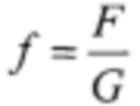
Оценивая процесс дополнительного разогрева потока в канале камеры, можно определить величины:Estimating the process of additional heating of the flow in the chamber channel, it is possible to determine the values:
- Q - количество тепла, подведенное к потоку;- Q is the amount of heat supplied to the flow;
- W- скорость потока рабочего тела;- W is the flow rate of the working fluid;
- p - давление потока по каналу;- p - flow pressure through the channel;
- ν - удельный объем камеры;- ν is the specific volume of the chamber;
- T - температура потока рабочего тела;- T is the temperature of the working fluid flow;
- 
Воспользуемся для оценок в приближении равновесного потока соотношениями равновесной термодинамики и газодинамики. Поведение потока рабочего тела в тепловой камере описывается следующими уравнениями:Let us use the relations of equilibrium thermodynamics and gas dynamics for estimates in the equilibrium flow approximation. The behavior of the working fluid flow in the heat chamber is described by the following equations:
состояния pν=RTstates pν = RT
где R - газовая постоянная (на 1 кг рабочего тела);where R is the gas constant (per 1 kg of the working fluid);
постоянства расхода 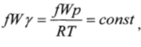
где γ - плотность потока рабочего тела;where γ is the flow density of the working fluid;
изменения импульса 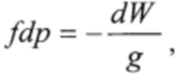
где g - ускорение свободного падения;where g is the acceleration of gravity;

где k - показатель адиабаты (величина Q берется на 1 кг массы рабочего тела).where k is the adiabatic index (the value of Q is taken per 1 kg of the working body mass).
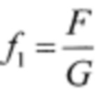
Перепишем систему уравнений в безразмерном виде для удобства расчета. Положим значения параметров потока в начале участка дополнительного подвода тепла следующими:Let's rewrite the system of equations in dimensionless form for the convenience of calculation. Let us set the values of the flow parameters at the beginning of the additional heat supply section as follows:
- W1 - скорость потока рабочего тела;- W 1 - flow rate of the working fluid;
- p1 - давление потока на входе в тепловой канал;- p 1 - flow pressure at the inlet to the heat channel;
- ν1 - удельный объем камеры;- ν 1 - specific volume of the chamber;
- T1 - температура потока рабочего тела;- T 1 - temperature of the flow of the working fluid;
- 
Тогда:Then:
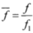
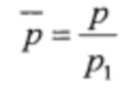
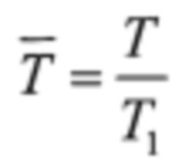

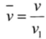
Величину безразмерного тепла, подводимого по длине, можно определить аналогично данным:The value of the dimensionless heat supplied along the length can be determined similarly to the data:
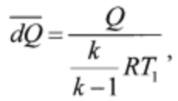
В результате система уравнений преобразуется к виду:As a result, the system of equations is converted to the form:
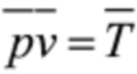
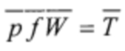
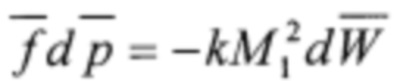


Если проинтегрировать последнее уравнение энергии, то получим выражение:If we integrate the last energy equation, we get the expression:

Связь между энергоподводом и скоростью потока в тепловой камере:The relationship between the energy supply and the flow rate in the heat chamber:

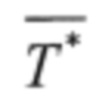
Температура торможения потока в начале участка теплоподвода 
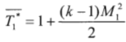
Кинетическая энергия потока и внутренняя позволят получить значение температуры торможения потока Tтормож.The kinetic energy of the flow will receive the internal and deceleration value of the flow temperature T decel.
Скорость истечения из ЭРД определяется аналогично ЖРД с тепловой камерой как (формула приведена в системе СИ):The outflow rate from the ERE is determined similarly to the LRE with a heat chamber as (the formula is given in SI system):
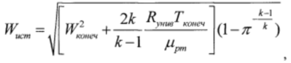
где μрт - молярная масса рабочего тела, π - степень расширения сопла, Rунив - универсальная газовая постоянная.where μ rt is the molar mass of the working fluid, π is the expansion ratio of the nozzle, R univ is the universal gas constant.
Используя связь количества энергии и времени пребывания потока в тепловом канале, в предположении, что доля энергии α от подведенного тепла Qподв идет на создание дополнительной кинетической и внутренней энергии потока, то, можно положить:Using the relationship between the amount of energy and the residence time of the flow in the heat channel, under the assumption that the share of energy α from the supplied heat Q sub goes to create additional kinetic and internal energy of the flow, then, we can put:
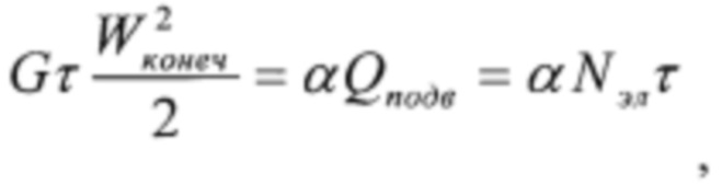
где τ - время пребывания потока в тепловой камере. В результате получим выражение для скорости истечения:where τ is the residence time of the flow in the heat chamber. As a result, we get an expression for the flow rate:

где αNэл=Nразряда - электрическая мощность, поглощенная разрядом в ЭРД.where αN el = N discharge is the electrical power absorbed by the discharge in the ERE.
Если принять численные значения μрт=28, Nразряда=300 Вт, степень расширения канала тепловой камеры - π=5 (диаметр увеличивается в 2,23 раза), k=1,2, G=10-6 кг/с, то при Tтормож.=4600 К получим величину скорости истечения - W ист =8530 м/с. То есть, дополнительный подвод тепла разгоняет поток до 8,5 км/с.If we take the numerical values μ rt = 28, N discharge = 300 W, the expansion ratio of the heat chamber channel is π = 5 (the diameter increases 2.23 times), k = 1.2, G = 10 -6 kg / s, then at T braking. = 4600 K, we obtain the value of the outflow velocity - W source = 8530 m / s. That is, the additional heat input accelerates the flow up to 8.5 km / s.
ЛитератураLiterature
1. Propellant Harvesting of Atmospheric Resources in Orbit / С. Jones, S. Kelley, D. Masse, A. Shah, C. Spells-Winski // NATIONAL INSTITUTE OF AEROSPACE GEORGIA INSTITUTE OF TECHNOLOGY.- 15 P.1. Propellant Harvesting of Atmospheric Resources in Orbit / S. Jones, S. Kelley, D. Masse, A. Shah, C. Spells-Winski // NATIONAL INSTITUTE OF AEROSPACE GEORGIA INSTITUTE OF TECHNOLOGY. - 15 P.
2. Nishiyama, K., / Air Breathing Ion Engine Concept," 54th International Astronautical Congress, Sept.-Oct. 2003, IAC-03-S4-02.2. Nishiyama, K., / Air Breathing Ion Engine Concept, "54th International Astronautical Congress, Sept.-Oct. 2003, IAC-03-S4-02.
3. Кириллов Л.И., Патент РФ №2122651, «ПРЯМОТОЧНЫЙ ВОЗДУШНО-ЭЛЕКТРИЧЕСКИЙ РЕАКТИВНЫЙ ДВИГАТЕЛЬ», от 27.05.2006, БИ: 15/2006.3. Kirillov LI, RF Patent №2122651, "DIRECT-FLOW AIR-ELECTRIC JET ENGINE", dated 27.05.2006, BI: 15/2006.
4. Квасников А.В. Теория жидкостных ракетных двигателей. - Л.: Судпромгиз.- 1959.- 542 с.4. Kvasnikov A.V. The theory of liquid propellant rocket engines. - L .: Sudpromgiz. - 1959. - 542 p.
Claims (1)
Priority Applications (1)
| Application Number | Priority Date | Filing Date | Title |
|---|---|---|---|
| RU2018134660A RU2727103C2 (en) | 2018-10-02 | 2018-10-02 | Electric jet propulsion plant |
Applications Claiming Priority (1)
| Application Number | Priority Date | Filing Date | Title |
|---|---|---|---|
| RU2018134660A RU2727103C2 (en) | 2018-10-02 | 2018-10-02 | Electric jet propulsion plant |
Publications (3)
| Publication Number | Publication Date |
|---|---|
| RU2018134660A3 RU2018134660A3 (en) | 2020-04-02 |
| RU2018134660A RU2018134660A (en) | 2020-04-02 |
| RU2727103C2 true RU2727103C2 (en) | 2020-07-20 |
Family
ID=70155453
Family Applications (1)
| Application Number | Title | Priority Date | Filing Date |
|---|---|---|---|
| RU2018134660A RU2727103C2 (en) | 2018-10-02 | 2018-10-02 | Electric jet propulsion plant |
Country Status (1)
| Country | Link |
|---|---|
| RU (1) | RU2727103C2 (en) |
Cited By (1)
| Publication number | Priority date | Publication date | Assignee | Title |
|---|---|---|---|---|
| RU2818410C1 (en) * | 2023-07-31 | 2024-05-02 | Общество с ограниченной ответственностью научно-производственное предприятие "ИнтерПолярис" (ООО НПП "ИнтерПолярис") | Electrojet propulsion system |
Families Citing this family (1)
| Publication number | Priority date | Publication date | Assignee | Title |
|---|---|---|---|---|
| CN119212145B (en) * | 2024-10-22 | 2025-10-03 | 中国航天空气动力技术研究院 | A hybrid ultra-high enthalpy arc heater |
Citations (4)
| Publication number | Priority date | Publication date | Assignee | Title |
|---|---|---|---|---|
| RU2122651C1 (en) * | 1997-01-06 | 1998-11-27 | Кириллов Леонид Иванович | Ramjet-electric engine |
| WO2008100642A2 (en) * | 2007-02-16 | 2008-08-21 | Ad Astra Rocket Company | Improved plasma source |
| RU2618636C2 (en) * | 2015-09-22 | 2017-05-05 | Федеральное государственное бюджетное образовательное учреждение высшего образования "Юго-Западный государственный университет" (ЮЗГУ) | Electrical rocket engine |
| RU2635951C1 (en) * | 2016-04-25 | 2017-11-17 | Федеральное государственное бюджетное образовательное учреждение высшего образования "Сибирский государственный университет науки и технологий имени академика М.Ф. Решетнева" (СибГУ им. М.Ф. Решетнева) | Method for creating electric propulsion thrust |
-
2018
- 2018-10-02 RU RU2018134660A patent/RU2727103C2/en active
Patent Citations (4)
| Publication number | Priority date | Publication date | Assignee | Title |
|---|---|---|---|---|
| RU2122651C1 (en) * | 1997-01-06 | 1998-11-27 | Кириллов Леонид Иванович | Ramjet-electric engine |
| WO2008100642A2 (en) * | 2007-02-16 | 2008-08-21 | Ad Astra Rocket Company | Improved plasma source |
| RU2618636C2 (en) * | 2015-09-22 | 2017-05-05 | Федеральное государственное бюджетное образовательное учреждение высшего образования "Юго-Западный государственный университет" (ЮЗГУ) | Electrical rocket engine |
| RU2635951C1 (en) * | 2016-04-25 | 2017-11-17 | Федеральное государственное бюджетное образовательное учреждение высшего образования "Сибирский государственный университет науки и технологий имени академика М.Ф. Решетнева" (СибГУ им. М.Ф. Решетнева) | Method for creating electric propulsion thrust |
Cited By (2)
| Publication number | Priority date | Publication date | Assignee | Title |
|---|---|---|---|---|
| RU2818410C1 (en) * | 2023-07-31 | 2024-05-02 | Общество с ограниченной ответственностью научно-производственное предприятие "ИнтерПолярис" (ООО НПП "ИнтерПолярис") | Electrojet propulsion system |
| RU2834336C1 (en) * | 2023-12-01 | 2025-02-05 | Акционерное общество "Научно-производственная корпорация "Космические системы мониторинга, информационно-управляющие и электромеханические комплексы" имени А.Г. Иосифьяна" АО "Корпорация "ВНИИЭМ" | Spacecraft air intake device with direct-flow electric rocket propulsion system |
Also Published As
| Publication number | Publication date |
|---|---|
| RU2018134660A3 (en) | 2020-04-02 |
| RU2018134660A (en) | 2020-04-02 |
Similar Documents
| Publication | Publication Date | Title |
|---|---|---|
| US10047732B2 (en) | Electrothermal device for a propulsion system, especially for a turbojet, propulsion system comprising such an electrothermal device, and associated method | |
| US2610464A (en) | Jet engine having fuel pumps driven by air turbine in thrust augmenting air duct | |
| RU2673123C2 (en) | Method and device for inerting a fuel tank | |
| EP1009927A1 (en) | Ejector ramjet engine | |
| RU2561757C1 (en) | Three-component air-jet engine | |
| Bityurin et al. | On a perspective of MHD technology in aerospace applications | |
| US20050034464A1 (en) | Jet aircraft electrical energy production system | |
| RU2727103C2 (en) | Electric jet propulsion plant | |
| Komornik et al. | Study of a hybrid gas generator for a ducted rocket | |
| Semenov et al. | Weakly ionized plasmas in aerospace applications | |
| RU2691702C2 (en) | Hypersonic ramjet engine | |
| US3382679A (en) | Jet engine with vaporized liquid feedback | |
| Van Wie et al. | Plasma aerodynamic flow control for hypersonic inlets | |
| RU2418969C2 (en) | Turbojet engine | |
| Imoto et al. | Enhancement of aerodynamic heating reduction in high enthalpy flows with opposing jet | |
| Kabeel et al. | The infrared suppression and cooling by utilizing ejectors | |
| CN111396276B (en) | Supersonic electric heating type stamping aerospace engine | |
| RU2645373C1 (en) | Turbo-jet engine and control method thereof | |
| RU2674292C1 (en) | Hypersonic turbojet engine | |
| RU2647919C1 (en) | Ramjet engine | |
| Tretyakov | The problems of combustion at supersonic flow | |
| RU154901U1 (en) | HYPERSONIC RANGE AIR REACTIVE ENGINE | |
| GOURDINE | Recent advances in magnetohydro-dynamic propulsion | |
| RU2447311C2 (en) | Operation mode and design of jet propulsion motor (versions) | |
| CN104963788A (en) | Hybrid engine applicable for aviation, spaceflight and navigation |