RU2727770C1 - Unmanned aerial vehicle - Google Patents
Unmanned aerial vehicle Download PDFInfo
- Publication number
- RU2727770C1 RU2727770C1 RU2020107110A RU2020107110A RU2727770C1 RU 2727770 C1 RU2727770 C1 RU 2727770C1 RU 2020107110 A RU2020107110 A RU 2020107110A RU 2020107110 A RU2020107110 A RU 2020107110A RU 2727770 C1 RU2727770 C1 RU 2727770C1
- Authority
- RU
- Russia
- Prior art keywords
- uav
- unmanned aerial
- aerial vehicle
- cable
- box
- Prior art date
Links
Images
Classifications
-
- B—PERFORMING OPERATIONS; TRANSPORTING
- B64—AIRCRAFT; AVIATION; COSMONAUTICS
- B64D—EQUIPMENT FOR FITTING IN OR TO AIRCRAFT; FLIGHT SUITS; PARACHUTES; ARRANGEMENT OR MOUNTING OF POWER PLANTS OR PROPULSION TRANSMISSIONS IN AIRCRAFT
- B64D5/00—Aircraft transported by aircraft, e.g. for release or reberthing during flight
Landscapes
- Engineering & Computer Science (AREA)
- Transportation (AREA)
- Aviation & Aerospace Engineering (AREA)
- Toys (AREA)
Abstract
Description
Изобретение относится к беспилотным летательным аппаратам (БПЛА), транспортируемым другими летательными аппаратами и отделяемым в полете для выведения на высотную траекторию полета.The invention relates to unmanned aerial vehicles (UAVs), transported by other aircraft and detachable in flight for launching to a high-altitude flight path.
Известен БПЛА, патент RU №2702261, принятый за прототип, содержащий узлы для крепления на пусковое устройство самолета-носителя вдоль фюзеляжа, выполненное с возможностью его отделения в полете, разгонную двигательную установку, систему управления его положением в автономном полете, полезную нагрузку, а также импульсные реактивные двигатели, создания импульса вращения вокруг поперечной оси, проходящей через центр тяжести беспилотного летательного аппарата, с увеличением угла тангажа, и компенсации этого импульса вращения.Known UAV, patent RU No. 2702261, taken as a prototype, containing assemblies for attachment to the launching device of the carrier aircraft along the fuselage, made with the possibility of separating it in flight, a booster propulsion system, a control system for its position in autonomous flight, a payload, and pulse jet engines, creating a rotation impulse around a transverse axis passing through the center of gravity of the unmanned aerial vehicle, with an increase in the pitch angle, and compensating for this rotation impulse.
Все существенные признаки прототипа совпадают с существенными признаками предлагаемого устройства.All essential features of the prototype coincide with the essential features of the proposed device.
Известный БПЛА изготавливают с формой внешней поверхности, обеспечивающей минимальное аэродинамическое сопротивление в обтекающем его потоке атмосферного воздуха, для уменьшения массы топлива разгонной двигательной установки, необходимой для выполнения полета и массы БПЛА в целом. Минимальное аэродинамическое сопротивление БПЛА после его отделения обеспечивает уменьшение ускорения торможения БПЛА в потоке обтекающего воздуха, вследствие чего увеличиваются время удаления БПЛА от самолета-носителя на безопасное расстояние и потеря высоты полета перед запуском разгонной двигательной установки. На компенсацию потери высоты полета БПЛА расходуется топливо разгонной двигательной установки, что увеличивает потребную массу топлива разгонной двигательной установки.The known UAV is made with the shape of the outer surface, which provides the minimum aerodynamic resistance in the flow of atmospheric air around it, to reduce the fuel mass of the booster propulsion system required for flight and the mass of the UAV as a whole. The minimum aerodynamic drag of the UAV after its separation provides a decrease in the acceleration of UAV deceleration in the stream of air flowing around, as a result of which the time for removing the UAV from the carrier aircraft to a safe distance and the loss of flight altitude before the launch of the accelerating propulsion system increase. To compensate for the loss of UAV flight altitude, the fuel of the booster propulsion system is consumed, which increases the required fuel mass of the booster propulsion system.
Техническим результатом, на достижение которого направлено техническое решение, является уменьшение потребной массы топлива разгонной двигательной установки.The technical result to be achieved by the technical solution is to reduce the required fuel mass of the booster propulsion system.
Для решения поставленной задачи беспилотный летательный аппарат, содержащий узлы для крепления на пусковое устройство самолета-носителя вдоль фюзеляжа, выполненное с возможностью его отделения в полете, разгонную двигательную установку, систему управления его положением в автономном полете, полезную нагрузку, а также импульсные реактивные двигатели, создания импульса вращения вокруг поперечной оси, проходящей через центр тяжести беспилотного летательного аппарата, с увеличением угла тангажа, и компенсации этого импульса вращения, снабжен тормозным парашютом, содержащим купол, трос и стропы, соединяющие купол с тросом, а также снабжен коробом, закрепленным на беспилотном летательном аппарате со стороны хвостовой части через устройство крепления короба, выполненное с возможностью расфиксации его крепления, и устройством крепления конечного участка троса в зоне верхней точки поверхности хвостовой части, выполненным с возможностью расфиксации крепления, при этом купол, стропы и начальный участок троса упакованы в короб, а конечный участок троса закреплен в устройстве его крепления.To solve this problem, an unmanned aerial vehicle containing nodes for attachment to the launch device of the carrier aircraft along the fuselage, made with the possibility of separating it in flight, a booster propulsion system, a system for controlling its position in autonomous flight, a payload, and pulse jet engines, creating an impulse of rotation around the transverse axis passing through the center of gravity of the unmanned aerial vehicle, with an increase in the pitch angle, and compensating for this impulse of rotation, is equipped with a braking parachute containing a canopy, a cable and slings connecting the canopy with a cable, and is also equipped with a box attached to the unmanned aerial vehicle aircraft from the tail side through the box fastening device, made with the possibility of unlocking its fastening, and the device for fastening the end section of the cable in the area of the upper point of the tail part surface, made with the possibility of unlocking the fastening, while the canopy, slings and the initial part of the cable is packed in a box, and the end section of the cable is fixed in the device for its fastening.
Отличительными признаками предлагаемого беспилотного летательного аппарата является то, что беспилотный летательный аппарат снабжен тормозным парашютом, содержащим купол, трос и стропы, соединяющие купол с тросом, а также снабжен коробом, закрепленным на беспилотном летательном аппарате со стороны хвостовой части через устройство крепления короба, выполненное с возможностью расфиксации его крепления, и устройством крепления конечного участка троса в зоне верхней точки поверхности хвостовой части, выполненным с возможностью расфиксации крепления, при этом купол, стропы и начальный участок троса упакованы в короб, а конечный участок троса закреплен в устройстве его крепления.Distinctive features of the proposed unmanned aerial vehicle is that the unmanned aerial vehicle is equipped with a braking parachute containing a canopy, a cable and slings connecting the canopy with a cable, and is also equipped with a box attached to the unmanned aerial vehicle from the tail end through a box fastening device made with the possibility of unlocking its fastening, and a device for fastening the end section of the cable in the area of the upper point of the surface of the tail part, made with the possibility of unlocking the fastening, while the dome, slings and the initial section of the cable are packed in a box, and the end section of the cable is fixed in the device for its fastening.
Благодаря наличию указанных отличительных признаков в совокупности с известными, достигается уменьшение времени выхода БПЛА на высотную траекторию полета и запаса топлива, необходимого для работы разгонной двигательной установки, а также уменьшение массы БПЛА в целом перед запуском разгонной двигательной установки.Due to the presence of these distinctive features in combination with the known ones, a decrease in the time the UAV reaches the high-altitude flight trajectory and the fuel supply required for the operation of the booster propulsion system, as well as a decrease in the mass of the UAV as a whole, before the launch of the acceleration propulsion system is achieved.
Предложенное техническое решение может найти применение в авиации, например, для запуска спутников связи или мониторинга поверхности, исследовательских аппаратов для изучения космических объектов, потоков космических излучений, состояния верхних слоев атмосферы.The proposed technical solution can find application in aviation, for example, for launching communication satellites or surface monitoring, research vehicles for studying space objects, cosmic radiation fluxes, and the state of the upper atmosphere.
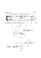
Устройство и его работа поясняются чертежами, фиг. 1 - фиг. 6.The device and its operation are illustrated by drawings, FIG. 1 to FIG. 6.
На фиг. 1 представлено устройство БПЛА, выводимого на высотную траекторию полета.FIG. 1 shows the UAV device, displayed on the high-altitude flight trajectory.
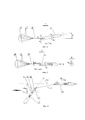
На фиг. 2 показано положение БПЛА в автономном полете после отделения от самолета-носителя при стабилизации его положения при торможении обтекающим потоком воздуха и расфиксации устройства крепления короба.FIG. 2 shows the position of the UAV in autonomous flight after separation from the carrier aircraft when its position is stabilized during braking by a stream of air and unlocking the box fastening device.
На фиг. 3 показано положение БПЛА в автономном полете после удаления от самолета-носителя на безопасное расстояние для выведения на высотную траекторию полета перед расфиксацией крепления конечного участка троса парашюта и включениием реактивного двигателя создания импульса вращения вокруг поперечной оси, проходящей через центр тяжести беспилотного летательного аппарата.FIG. 3 shows the position of the UAV in autonomous flight after moving away from the carrier aircraft to a safe distance for launching to the high-altitude flight path before unlocking the attachment of the end section of the parachute cable and turning on the jet engine to create a rotation impulse around the transverse axis passing through the center of gravity of the unmanned aerial vehicle.
На фиг. 4 показан вид фиг. 2 по стрелке А при случайном отклонении или колебаниях БПЛА по курсу на угол β, поясняющий формирование стабилизирующего момента Мβ от силы натяжения троса парашюта, противоположного направления, возвращающего БПЛА в исходное состояние.FIG. 4 shows a view of FIG. 2 in the direction of arrow A in case of accidental deviation or oscillations of the UAV along the course at an angle β, explaining the formation of a stabilizing moment M β from the tension force of the parachute cable, the opposite direction, returning the UAV to its original state.
На фиг. 5 показан виды фиг. 2 по стрелке А при случайном отклонении или колебаниях БПЛА по крену на угол γ (вращение вокруг продольной оси БПЛА) поясняющий формирование стабилизирующего момента Мγ от силы натяжения троса парашюта, противоположного направления, возвращающего БПЛА в исходное состояние.FIG. 5 shows views of FIG. 2 in the direction of arrow A in case of random deviation or oscillations of the UAV along the roll at an angle γ (rotation around the longitudinal axis of the UAV) explaining the formation of the stabilizing moment M γ from the pulling force of the parachute cable in the opposite direction, returning the UAV to its original state.
На фиг. 6 показано положение БПЛА в автономном полете относительно самолета-носителя при запуске разгонной двигательной установки БПЛА.FIG. 6 shows the position of the UAV in autonomous flight relative to the carrier aircraft when the UAV's booster propulsion system is launched.
Представленный на фиг. 1-6 БПЛА 1 содержит узлы крепления на пусковое устройство 2 самолета-носителя вдоль его фюзеляжа 3, состоящие из переднего упора 4, замковой ниши 5 для подъема БПЛА 1 и его крепления на пусковом устройстве 2, и заднего упора 6, разгонную двигательную установку 7, систему управления его положением в автономном полете, включающую блок 8 управления, сообщенный с устройством 9 стабилизации положения БПЛА 1 после отделения от пускового устройства 2, и с устройством 10 управления положением БПЛА 1 после запуска разгонной двигательной установки 7. БПЛА 1 снабжен полезной нагрузкой 11, импульсным реактивным двигателем 12, для создания импульса вращения вокруг поперечной оси, проходящей через центр 13 тяжести (ЦТ) БПЛА 1, с увеличением угла тангажа, и импульсным реактивным двигателем 14, для создания импульса компенсации вращения БПЛА 1 вокруг поперечной оси, проходящей через центр 13 тяжести. Пусковое устройство 2 содержит раздвижные элементы 15 для подъема БПЛА 1 и его крепления на пусковом устройстве 2 и выполнено с возможностью отделения БПЛА 1 от самолета-носителя в полете. БПЛА 1 снабжен тормозным парашютом, содержащим купол 16, стропы 17 и трос 18. Стропы 17 соединяют купол 16 с тросом 18. БПЛА 1 снабжен коробом 19, закрепленным со стороны хвостовой части БПЛА 1 через устройство 20 крепления короба 19, выполненное с возможностью расфиксации его крепления, и устройством 21 крепления конечного участка троса 18 в зоне верхней точки поверхности хвостовой части БПЛА 1, выполненным с возможностью расфиксации его крепления, при этом купол 16, стропы 17 и начальный участок троса 18 упакованы в короб 19, а конечный участок троса 18 закреплен в устройстве 21 его крепления.Shown in FIG. 1-6
БПЛА 1 работает следующим образом. Средствами подъема пускового устройства 2 (на чертежах не показаны) БПЛА 1 устанавливается на пусковое устройство 2 до контакта с передним и задним упорами 4 и 6, раздвижные элементы 15 фиксируются в замковой нише 5. Самолет-носитель выполняет полет к месту отцепки с подъемом на высоту отцепки. В месте отцепки расфиксируются раздвижные элементы 15 и БПЛА 1 под действием силы тяжести отделяется от пускового устройства 2. При необходимости, пусковое устройство 2 может содержать устройство отталкивания БПЛА 1 (на чертежах не показано). После отделения БПЛА 1, по команде блока 8 управления задействуется устройство 9, обеспечивая стабилизацию положения БПЛА 1 в автономном полете, при котором импульсный реактивный двигатель 12 располагается в нижней части БПЛА 1, а импульсный реактивный двигатель 14, соответственно, в верхней. При стабилизации положения БПЛА 1 расфиксируют устройство 20 крепления короба 19, что приводит к отделению от БПЛА 1 короба 19. Купол 16, его стропы 17 и начальный участок троса 18 оказываются в потоке воздуха, обтекающего БПЛА 1. Купол 16 раскрывается (см. фиг. 2), воспринимая динамическое давление обтекающего потока воздуха. Сила FП от динамического давления потока воздуха на купол 16 через стропы 17 и трос 18 передается в зону верхней точки поверхности хвостовой части БПЛА 1. Сила FП направлена в противоположную сторону от направления полета БПЛА 1 и создает дополнительное, по отношению к торможению БПЛА 1 обтекающим потоком воздуха, отрицательное ускорение, действующее на БПЛА 1 и дополнительно уменьшающее его скорость полета, по отношению к скорости самолета-носителя. Кроме того, сила FП благодаря действию в зоне верхней точки поверхности хвостовой части БПЛА 1 создает момент Мϑ вращения БПЛА 1 относительно его центра 13 тяжести, увеличивающий угол ϑ тангажа: Мϑ=FП*hϑ, где hϑ - плечо силы FП относительно центра 13 тяжести БПЛА 1 (см. фиг. 2), поэтому к моменту достижения необходимого расстояния (Lуд) удаления БПЛА 1 от самолета-носителя, обеспечивающего безопасность самолета-носителя при выведении БПЛА 1 на высотную траекторию полета, при запуске импульсного реактивного двигателя 12, БПЛА 1 располагается под предварительным углом ϑП тангажа (см. фиг. 3), поэтому для достижения значения угла ϑЗАП тангажа БПЛА 1, необходимого для запуска разгонной двигательной установки 7, импульсный реактивный двигатель 12, по сравнению с прототипом, обеспечивает увеличение угла тангажа БПЛА 1 на меньшую величину (ϑЗАП-ϑп), что обеспечивает уменьшение затрат топлива на увеличение угла тангажа, соответственно, уменьшаются и затраты топлива импульсного реактивного двигателя 14 создания импульса компенсации вращения БПЛА 1. Благодаря дополнительному уменьшению скорости полета БПЛА 1, по отношению к скорости самолета-носителя, уменьшается время достижения необходимого расстояния (Lуд) удаления БПЛА 1 от самолета-носителя, обеспечивающее безопасность самолета-носителя при выведении БПЛА 1 на высотную траекторию полета. Благодаря уменьшению времени достижения необходимого расстояния (Lуд, см. фиг. 3) удаления БПЛА 1 от самолета-носителя, уменьшается также и потеря высоты (АН) полета БПЛА 1, относительно высоты полета самолета-носителя, при включении импульсного реактивного двигателя 12 и, соответственно, при запуске разгонной двигательной установки 7, что обеспечивает уменьшение времени выведения БПЛА 1 на высотную траекторию полета, и необходимого для этого запаса топлива разгонной двигательной установки 7, уменьшение ее массы и массы БПЛА 1 в целом. Уменьшение массы БПЛА 1 обеспечивает его большее ускорение при действии силы тяги разгонной двигательной установки 7, что дополнительно уменьшает время выведения БПЛА 1 на высотную траекторию полета. Кроме того, при действии силы FП и случайном повороте или колебаниях БПЛА 1 по курсу на угол β (см. фиг. 4), сила FП, относительно центра 13 тяжести, действует на плечо hβ, создавая момент вращения Мβ=FП*hβ, противоположного направления, который возвращает БПЛА 1 в исходное состояние, обеспечивая стабилизацию БПЛА 1 по курсу. Аналогично, момент вращения противоположного действия формируется и при повороте БПЛА 1 по курсу в противоположном направлении (на угол минус β). При действии силы FП и случайном повороте или колебаниях БПЛА 1 по крену вокруг его продольной оси на угол γ (см. фиг. 5), точка приложения силы FП смещается относительно вертикальной плоскости, при этом трос 18 располагается под углом к ней и сила FП раскладывается на продольную составляющую (FП-ПР) и боковую составляющую (FП-Б). Боковая составляющая FП-Б, относительно центра 13 тяжести, действует на плече hγ, создавая момент вращения Мγ=FП-Б*hγ, противоположного действия, который возвращает БПЛА 1 в исходное состояние, обеспечивая стабилизацию БПЛА 1 по крену. Аналогично, момент вращения противоположного действия формируется и при повороте БПЛА 1 по крену в противоположном направлении (на угол минус γ). Благодаря стабилизации БПЛА 1 по курсу и крену уменьшается запас топлива, необходимый для работы устройства 9 стабилизации положения БПЛА 1 от момента его отделения от пускового устройства 2 до достижения необходимого расстояния Lуд. После достижения необходимого расстояния Lуд удаления БПЛА 1 от самолета-носителя блок 8 управления задействует расфиксацию устройства 21 крепления конечного участка троса 18 и импульсный реактивный двигатель 12, который обеспечивает увеличение угла тангажа БПЛА 1. В процессе увеличение угла тангажа БПЛА 1 до необходимого значения ϑЗАП (фиг. 6) по сигналам блока 8 управления задействуется импульсный реактивный двигатель 14, обеспечивая компенсацию импульса вращения БПЛА 1 вокруг поперечной оси, проходящей через ЦТ 13, а после уменьшения угловой скорости вращения БПЛА 1 выполняется запуск разгонной двигательной установки 7.
Claims (1)
Priority Applications (1)
| Application Number | Priority Date | Filing Date | Title |
|---|---|---|---|
| RU2020107110A RU2727770C1 (en) | 2020-02-17 | 2020-02-17 | Unmanned aerial vehicle |
Applications Claiming Priority (1)
| Application Number | Priority Date | Filing Date | Title |
|---|---|---|---|
| RU2020107110A RU2727770C1 (en) | 2020-02-17 | 2020-02-17 | Unmanned aerial vehicle |
Publications (1)
| Publication Number | Publication Date |
|---|---|
| RU2727770C1 true RU2727770C1 (en) | 2020-07-23 |
Family
ID=71741444
Family Applications (1)
| Application Number | Title | Priority Date | Filing Date |
|---|---|---|---|
| RU2020107110A RU2727770C1 (en) | 2020-02-17 | 2020-02-17 | Unmanned aerial vehicle |
Country Status (1)
| Country | Link |
|---|---|
| RU (1) | RU2727770C1 (en) |
Citations (4)
| Publication number | Priority date | Publication date | Assignee | Title |
|---|---|---|---|---|
| US4901949A (en) * | 1988-03-11 | 1990-02-20 | Orbital Sciences Corporation Ii | Rocket-powered, air-deployed, lift-assisted booster vehicle for orbital, supraorbital and suborbital flight |
| UA54311C2 (en) * | 2002-07-18 | 2005-03-15 | State M K Yanhel Design Office | Aviation rocket complex for transporting and launching a rocket in upper layers of atmosphere |
| JP2018135025A (en) * | 2017-02-23 | 2018-08-30 | 株式会社Subaru | Flying vehicle for unmanned aircraft transportation and transportation method of unmanned aircraft |
| RU2702261C2 (en) * | 2018-03-16 | 2019-10-07 | Акционерное Общество "Государственное Машиностроительное Конструкторское Бюро "Радуга" Имени А.Я. Березняка" | Unmanned aerial vehicle |
-
2020
- 2020-02-17 RU RU2020107110A patent/RU2727770C1/en active
Patent Citations (4)
| Publication number | Priority date | Publication date | Assignee | Title |
|---|---|---|---|---|
| US4901949A (en) * | 1988-03-11 | 1990-02-20 | Orbital Sciences Corporation Ii | Rocket-powered, air-deployed, lift-assisted booster vehicle for orbital, supraorbital and suborbital flight |
| UA54311C2 (en) * | 2002-07-18 | 2005-03-15 | State M K Yanhel Design Office | Aviation rocket complex for transporting and launching a rocket in upper layers of atmosphere |
| JP2018135025A (en) * | 2017-02-23 | 2018-08-30 | 株式会社Subaru | Flying vehicle for unmanned aircraft transportation and transportation method of unmanned aircraft |
| RU2702261C2 (en) * | 2018-03-16 | 2019-10-07 | Акционерное Общество "Государственное Машиностроительное Конструкторское Бюро "Радуга" Имени А.Я. Березняка" | Unmanned aerial vehicle |
Similar Documents
| Publication | Publication Date | Title |
|---|---|---|
| EP2279945B1 (en) | Launching system and launching apparatus | |
| US6776373B1 (en) | Aircraft escape cabin | |
| US7946530B1 (en) | Modular adaptive configured helicopter | |
| US10124890B2 (en) | Modular nacelles to provide vertical takeoff and landing (VTOL) capabilities to fixed wing aerial vehicles, and associated systems and methods | |
| US5526999A (en) | Spacecraft with a crew escape system | |
| RU2175933C2 (en) | Means method and system for launching spacecraft on basis of towed glider | |
| RU2191145C2 (en) | System of injection of payload into low-altitude near-earth orbit | |
| US6913224B2 (en) | Method and system for accelerating an object | |
| US9738383B2 (en) | Remote controlled aerial reconnaissance vehicle | |
| RU97110200A (en) | RUNNING FACILITIES FOR SPACE VEHICLES, PERFORMED AS A PLANER AND TOWED TO THE RUNNING HEIGHT OF A USUAL PLANE | |
| AU2022441167B2 (en) | System and method for improved air-launch of a launch vehicle from a towed aircraft | |
| IL315744B2 (en) | Aerospace system and method for delivering payload to orbit and to midair | |
| RU181026U1 (en) | Multipurpose Unmanned Aerial Vehicle | |
| US12391413B2 (en) | Systems and methods for airborne recovery and launch of aerial vehicles | |
| CN106767157B (en) | A transport aircraft jumping type air-launched carrier rocket method | |
| RU2702261C2 (en) | Unmanned aerial vehicle | |
| RU2727770C1 (en) | Unmanned aerial vehicle | |
| RU2727363C1 (en) | Method for unmanned aerial vehicle flight to altitude flight path | |
| RU198132U1 (en) | Unmanned aerial vehicle | |
| RU2401779C1 (en) | Air rocket complex | |
| RU2682944C1 (en) | Method of placing unmanned aerial vehicle in high-attitude flight trajectory | |
| EP0631931B1 (en) | Spacecraft with an escape system for the crew | |
| RU184666U1 (en) | Unmanned aerial vehicle | |
| RU2114030C1 (en) | High speed flying vehicle | |
| RU2258639C1 (en) | Method of air start of unmanned flying vehicle and external suspension system for realization of this method |