RU2773473C1 - Integrated tank integrity system - Google Patents
Integrated tank integrity system Download PDFInfo
- Publication number
- RU2773473C1 RU2773473C1 RU2021127188A RU2021127188A RU2773473C1 RU 2773473 C1 RU2773473 C1 RU 2773473C1 RU 2021127188 A RU2021127188 A RU 2021127188A RU 2021127188 A RU2021127188 A RU 2021127188A RU 2773473 C1 RU2773473 C1 RU 2773473C1
- Authority
- RU
- Russia
- Prior art keywords
- tank
- explosion
- inert gas
- oil
- compensator
- Prior art date
Links
Images
Abstract
Description
Изобретение относится к области пожарной безопасности, а именно к средствам защиты от пожара и тушения пожаров в резервуарах, предназначенных для хранения взрывоопасных веществ, таких как нефть и нефтепродукты. Изобретение может найти применение в нефтяной, нефтеперерабатывающей и нефтехимической промышленности, а также непосредственно связано с деятельностью по хранению и транспортировке нефти и нефтепродуктов.The invention relates to the field of fire safety, and in particular to means of fire protection and extinguishing fires in tanks intended for the storage of explosive substances such as oil and oil products. The invention can find application in the oil, oil refining and petrochemical industries, and is also directly related to the storage and transportation of oil and oil products.
Причинами возникновения взрывов и пожаров в резервуарах для хранения нефти и нефтепродуктов могут быть:The causes of explosions and fires in tanks for storing oil and oil products can be:
- нарушение правил пожарной безопасности при выполнении технологических работ;- violation of fire safety rules when performing technological work;
- появление внутри резервуара электрической дуги, возникающей в электрическом оборудовании при грозовых и коммутационных перенапряжениях, внешних и внутренних коротких замыканиях, при наличии дефектов в изоляции оборудования.- the appearance of an electric arc inside the tank that occurs in electrical equipment during lightning and switching overvoltages, external and internal short circuits, if there are defects in the insulation of the equipment.
В первом случае сначала происходит возгорание взрывоопасной жидкости, а затем, по мере развития пожара, взрыв и разрушение резервуара.In the first case, the explosive liquid ignites first, and then, as the fire develops, the explosion and destruction of the tank.
Во втором случае в зоне электрической дуги под действием ее высокой температуры происходит разложение взрывоопасной жидкости и появление горючих газов, таких как водород, ацетилен, метан и других. Быстрое увеличение объема этих газов повышает давление внутри резервуара, такой быстрый рост объема горючих газов, при определенной мощности электрической дуги и времени ее горения, приводит к взрыву в резервуаре, способному привести к разрыву резервуара и пожару.In the second case, in the zone of an electric arc, under the influence of its high temperature, an explosive liquid decomposes and combustible gases, such as hydrogen, acetylene, methane, and others, appear. A rapid increase in the volume of these gases increases the pressure inside the tank, such a rapid increase in the volume of combustible gases, at a certain power of the electric arc and its burning time, leads to an explosion in the tank, which can lead to a rupture of the tank and a fire.
При взрыве паров нефти или нефтепродукта в наземном металлическом резервуаре, в большинстве случаев, происходит отрыв стенки резервуара от нижнего сварного шва и кратковременный подъем («подскок») стенки над поверхностью земли. В результате разрыва уторного шва и подъема резервуара происходит разлив горючей жидкости в обвалование и ее воспламенение, при этом подводящие трубопроводы установок пожаротушения и охлаждения резервуара оказываются поврежденными, создается угроза пожара соседним резервуарам и жизни людей, находящихся на объекте и участвующих в тушении пожара. Площадь пожара увеличивается до площади обвалования и его тушение возможно только с привлечением мобильных средств пожаротушения.During the explosion of oil or oil product vapors in a ground metal tank, in most cases, the tank wall is separated from the lower weld and a short-term rise (“jump”) of the wall above the ground surface occurs. As a result of the rupture of the morning seam and the lifting of the tank, a flammable liquid spills into the embankment and ignites, while the supply pipelines of the fire extinguishing and cooling systems of the tank are damaged, a fire threat is created to neighboring tanks and the lives of people located at the facility and participating in fire extinguishing. The fire area increases to the area of the embankment and its extinguishing is possible only with the involvement of mobile fire extinguishing equipment.
Известен способ противопожарной защиты резервуаров для хранения жидких горючих веществ, заключающийся в том, что после обнаружения пожара доставка, по меньшей мере, одного огнетушащего вещества осуществляется сквозь слой горючего вещества через размещенный в резервуаре, по меньшей мере, один перфорированный сухотруб, состоящий, по меньшей мере, из одной секции, проходящей сквозь слой горючего вещества. При этом секции сухотруба покрыты синтетической пленкой или синтетическим покрытием, которое после возникновения пожара разрушается выше уровня жидкого горючего вещества, хранящегося в резервуаре, под воздействием факторов пожара и открывает перфорацию сухотруба непосредственно над поверхностью жидкого горючего вещества и/или в зоне горения в непосредственной близости от поверхности, независимо от уровня взлива жидкого горючего вещества в резервуаре, через которую и осуществляется доставка, по меньшей мере, одного огнетушащего вещества путем подачи непосредственно на поверхность жидкого горючего вещества от системы пожаротушения. В качестве огнетушащего вещества возможно использование огнетушащих газовых составов, например, СО2, азот, хладоны 125, 227еа, 318Ц, аргон, инерген и т.п. (см. RU 2425702 С1, опубл. 10.08.2011, патентообладатель: Закрытое акционерное общество "Научно-производственное объединение Вариант-Гидротехника" (ЗАО "НПО Вариант-Гидротехника") (RU)). Устройство, реализующее рассматриваемый способ, работает следующим образом. При возникновении пожара в резервуаре над поверхностью жидкого горючего вещества возникает интенсивное горение, которое в свою очередь разрушает синтетическую пленку или синтетическое покрытие над поверхностью жидкой горючей жидкости и/или зоне горения независимо от уровня взлива жидкости в резервуаре и открывает отверстия перфорации сухотруба, находящиеся над жидким горючим веществом. После обнаружения пожара в резервуаре или резком увеличении температуры извещателями системы обнаружения пожара подается сигнал на запуск системы пожаротушения, которая обеспечивает подачу необходимого количества огнетушащего вещества через распределяющий трубопровод, по перфорированному сухотрубу непосредственно на поверхность горючей жидкости. Происходит тушение пожара.A known method of fire protection of tanks for storing liquid combustible substances, which consists in the fact that after a fire is detected, the delivery of at least one fire extinguishing agent is carried out through a layer of combustible substance through at least one perforated dry pipe located in the tank, consisting of at least at least from one section passing through a layer of combustible substance. At the same time, dry pipe sections are covered with a synthetic film or synthetic coating, which, after a fire breaks down above the level of the liquid combustible substance stored in the tank, under the influence of fire factors and opens the perforation of the dry pipe directly above the surface of the liquid combustible substance and / or in the combustion zone in the immediate vicinity of surface, regardless of the level of pouring liquid combustible substance in the tank, through which at least one fire extinguishing agent is delivered by supplying liquid combustible substance directly to the surface from the fire extinguishing system. As a fire extinguishing agent, it is possible to use fire extinguishing gas compositions, for example, CO 2 , nitrogen, freons 125, 227ea, 318C, argon, inergen, etc. (see RU 2425702 C1, publ. 08/10/2011, patent holder: Closed Joint Stock Company "Scientific and Production Association Variant-Hydrotechnica" (CJSC "NPO Variant-Hydrotechnica") (RU)). The device that implements the considered method operates as follows. In the event of a fire in a tank above the surface of a liquid combustible substance, intense combustion occurs, which in turn destroys the synthetic film or synthetic coating above the surface of the liquid combustible liquid and / or the combustion zone, regardless of the level of liquid injection in the tank and opens the perforation holes of the dry pipe located above the liquid combustible substance. After detecting a fire in a tank or a sharp increase in temperature, the detectors of the fire detection system send a signal to start the fire extinguishing system, which ensures the supply of the required amount of fire extinguishing agent through the distribution pipeline, through a perforated dry pipe directly to the surface of the combustible liquid. The fire is extinguished.
Недостаток вышеописанного аналога заключается в применении системы пожаротушения только в целях устранения возгорания и невозможности системы сохранить конструктивную целостность резервуара при взрыве внутри резервуара, что снижает безопасность использования резервуара. Кроме того, конструкция оборудования пожаротушения устроена таким образом, что азот подается в резервуар из небольших по сравнению с резервуаром отверстий сухотруба (перфораций), расположенных в центре резервуара или над поверхностью воспламеняющейся жидкости, в связи с чем поступает в резервуар довольно медленно и не обеспечивает быстрого уменьшения концентрации кислорода («разбавления» кислорода), что снижает эффективность пожаротушения. При этом не исключается риск повреждения (сжатия, деформирования) перфорированного сухотруба, вызванного избыточным давлением продуктов взрыва, вследствие чего сухотруб не сможет эффективно осуществлять выпуск огнетушащего вещества при тушении возгорания, что влияет на надежность системы пожаротушения.The disadvantage of the above-described analogue is the use of a fire extinguishing system only to eliminate the fire and the inability of the system to maintain the structural integrity of the tank in case of an explosion inside the tank, which reduces the safety of using the tank. In addition, the design of fire extinguishing equipment is designed in such a way that nitrogen is supplied to the tank from dry pipe holes (perforations) that are small compared to the tank, located in the center of the tank or above the surface of the flammable liquid, and therefore it enters the tank rather slowly and does not provide fast decrease in oxygen concentration (“dilution” of oxygen), which reduces the effectiveness of fire extinguishing. This does not exclude the risk of damage (compression, deformation) of the perforated dry pipe caused by excessive pressure of the explosion products, as a result of which the dry pipe will not be able to effectively release the fire extinguishing agent when extinguishing a fire, which affects the reliability of the fire extinguishing system.
Известен способ тушения пожара в резервуаре путем подачи газодисперсной огнетушащей смеси в зону горения жидкости (см. RU 2258549 С1, опубл. 20.08.2005, патентообладатель: Общество с ограниченной ответственностью "ЛИТИНТЕРН КОНСАЛТ"). В случае пожара в резервуаре с фиксированной крышей, содержащей легковоспламеняющиеся жидкости, от независимого извещателя, установленного, например, внутри резервуара, подается сигнал на пускозапорное устройство, которое вскрывает газовой баллон, содержащий газообразный и/или сжиженный флегматизатор и/или ингибитор горения (например, азот), после чего последний по сифонной трубке поступает в емкость с герметичной крышкой. При достижении в данной емкости давления 1 МПа образуется устойчивая газодисперсная смесь, которая вскрывает мембрану или клапан и распыляется на 360° компактными струями с углом расхождения 5-15° в плоскости, параллельной «зеркалу» горючей или легковоспламеняющейся жидкости. Недостаток данного аналога также заключается в применении описанной системы пожаротушения только в целях устранения возгорания и невозможности системы сохранить конструктивную целостность резервуара при взрыве внутри резервуара, что снижает безопасность использования резервуара. Кроме того, конструкция оборудования пожаротушения устроена таким образом, что флегматизатор и/или ингибитор горения подается через небольшое по сравнению с резервуаром отверстие, расположенное в центре резервуара или над поверхностью воспламеняющейся жидкости, в связи с чем флегматизатор и/или ингибитор поступает в резервуар довольно медленно и не обеспечивает быстрого уменьшения концентрации кислорода («разбавления» кислорода), что снижает эффективность пожаротушения, при этом не исключается риск повреждения оборудования системы, вызванного избыточным давлением продуктов взрыва, вследствие чего система не сможет осуществлять выпуск флегматизатора и/или ингибитора горения, что снижает надежность системы пожаротушения.A known method of extinguishing a fire in a tank by supplying a gas-dispersed fire extinguishing mixture into the liquid combustion zone (see RU 2258549 C1, publ. 20.08.2005, patent holder: Limited Liability Company "LITINTERN CONSULT"). In the event of a fire in a tank with a fixed roof containing flammable liquids, an independent detector installed, for example, inside the tank, sends a signal to the start-and-lock device, which opens a gas cylinder containing a gaseous and / or liquefied phlegmatizer and / or flame retardant (for example, nitrogen), after which the latter enters a container with a sealed lid through a siphon tube. When a pressure of 1 MPa is reached in this container, a stable gas-dispersed mixture is formed, which opens the membrane or valve and sprays 360 ° in compact jets with a divergence angle of 5-15 ° in a plane parallel to the “mirror” of a combustible or flammable liquid. The disadvantage of this analog also lies in the use of the described fire extinguishing system only in order to eliminate the fire and the inability of the system to maintain the structural integrity of the tank in case of an explosion inside the tank, which reduces the safety of using the tank. In addition, the design of fire extinguishing equipment is designed in such a way that the phlegmatizer and / or flame retardant is supplied through a small hole compared to the tank, located in the center of the tank or above the surface of the flammable liquid, and therefore the phlegmatizer and / or flame retardant enters the tank rather slowly and does not provide a rapid decrease in the oxygen concentration (“dilution” of oxygen), which reduces the effectiveness of fire extinguishing, while the risk of damage to the system equipment caused by excessive pressure of the explosion products is not excluded, as a result of which the system will not be able to release the phlegmatizer and / or flame retardant, which reduces reliability of the fire extinguishing system.
К наиболее близкому аналогу (прототипу) можно отнести противопожарное оборудование резервуара с нефтепродуктами, раскрытое в патенте на полезную модель RU 170678 U1, опубл. 03.05.2017, патентообладатель: Федеральное государственное автономное образовательное учреждение высшего образования "Сибирский федеральный университет" (RU). Противопожарное оборудование резервуара с нефтепродуктами содержит плавающую крышу, установленную в резервуаре с возможностью вертикального перемещения в зависимости от уровня нефтепродукта по направляющей стойке, жестко закрепленной на дне в центре резервуара, и форсунки для введения огнетушащего вещества, например, инертного негорючего газа азота, подача которого осуществляется по трубопроводу от генератора азота, при этом трубопровод снабжен задвижкой. Основным узловым элементом противопожарного оборудования резервуара является плавающая крыша, выполненная с возможностью регулирования площади ее поверхности от уменьшенной в исходном положении для снижения силы вероятного ударного воздействия, приходящейся на поверхность, до максимальной в рабочем положении для эффективной защиты при ликвидации возгорания нефтепродукта. Для осуществления работы противопожарного оборудования резервуара в автоматическом режиме в крыше резервуара установлены датчики контроля концентрации паров газа, связанные с пунктом управления. При наступлении критической концентрации паров или аварийной ситуации в случае возникновения возгорания с пульта управления подается сигнал на крышу для изменения ее площади. Одновременно с подачей сигнала на крышу открывается задвижка на трубопроводе и из генератора азота через трубопровод и форсунки, расположенные на дне резервуара, начинает поступать инертный негорючий газ азот, обладающий свойством объемного пожаротушения. Азот обеспечивает ликвидацию возгорания за счет охлаждения горючего нефтепродукта, а также создает среду с пониженным содержанием кислорода, при которой процесс горения становится невозможным.The closest analogue (prototype) is the fire-fighting equipment of a tank with oil products, disclosed in the utility model patent RU 170678 U1, publ. 05/03/2017, patent holder: Federal State Autonomous Educational Institution of Higher Education "Siberian Federal University" (RU). The fire-fighting equipment of a tank with oil products contains a floating roof installed in the tank with the possibility of vertical movement, depending on the level of the oil product, along a guide post rigidly fixed at the bottom in the center of the tank, and nozzles for introducing a fire extinguishing agent, for example, inert, non-combustible nitrogen gas, which is supplied through the pipeline from the nitrogen generator, while the pipeline is equipped with a valve. The main key element of the fire-fighting equipment of the tank is a floating roof, made with the possibility of adjusting its surface area from reduced in the initial position to reduce the probable impact force falling on the surface, to the maximum in the working position for effective protection in the elimination of an oil product fire. To carry out the operation of the fire-fighting equipment of the tank in automatic mode, sensors for monitoring the concentration of gas vapors associated with the control point are installed on the roof of the tank. When a critical concentration of vapors occurs or an emergency occurs in the event of a fire, a signal is sent from the control panel to the roof to change its area. Simultaneously with the signal to the roof, the valve on the pipeline opens and from the nitrogen generator through the pipeline and nozzles located at the bottom of the tank, inert non-combustible nitrogen gas begins to flow, which has the property of volumetric fire extinguishing. Nitrogen ensures the elimination of fire by cooling the combustible oil product, and also creates an environment with a low oxygen content, in which the combustion process becomes impossible.
В прототипе устранены некоторые недостатки известных аналогов, поскольку она решает не только задачу пожаротушения, но и снижения силы, приходящейся на поверхность, от действия ударной волны при взрыве. Однако к недостатку прототипа можно отнести сложность конструкции оборудования для пожаротушения, срабатывание которого зависит, как от исправности механизмов сложной плавающей крыши, так и от работоспособности датчиков контроля концентрации паров газа, связанных с пунктом управления, что влияет на надежность системы пожаротушения. В случае выхода из строя датчиков контроля концентрации паров газа или заклинивания одного из многочисленных узлов сложной конструкции плавающей крыши, вызванного избыточным давлением продуктов взрыва, система пожаротушения не будет приведена в действие, взрыв не будет погашен, целостность резервуара будет нарушена, а пожар не будет предупрежден. Кроме того, в данной системе не исключается риск повреждения подачи инертного газа/флегматизатора при выходе из строя (повреждения) трубопровода от генератора азота, вызванного избыточным давлением продуктов взрыва, при взрыве внутри резервуара, что также влияет на надежность срабатывания системы и, как следствие, на безопасность использования резервуара. В прототипе, как и в известных аналогах, азот подается в резервуар из небольших по сравнению с объемом резервуара отверстий (форсунок), в связи с чем поступает в резервуар постепенно, довольно медленно и не обеспечивает быстрого уменьшения концентрации кислорода («разбавления» кислорода), что снижает эффективность пожаротушения. Также к недостатку прототипа следует отнести ограниченность применения из-за невозможности его использования в резервуарах с понтоном, ввиду расположения понтона между крышей и поверхностью рабочей среды, а также наличию настила понтона, что не позволяет использовать крышу в целях гашения взрывной волны, так как возникающая от действия ударной волны при взрыве в резервуаре сила в первую очередь направляется на настил понтона.The prototype eliminated some of the shortcomings of known analogues, since it solves not only the problem of fire extinguishing, but also reducing the force attributable to the surface from the action of a shock wave during an explosion. However, the disadvantage of the prototype can be attributed to the complexity of the design of fire extinguishing equipment, the operation of which depends both on the health of the mechanisms of the complex floating roof and on the operability of the sensors for monitoring the concentration of gas vapors associated with the control point, which affects the reliability of the fire extinguishing system. In the event of failure of gas vapor concentration control sensors or jamming of one of the numerous components of the complex structure of the floating roof, caused by excessive pressure of the explosion products, the fire extinguishing system will not be activated, the explosion will not be extinguished, the integrity of the tank will be compromised, and the fire will not be prevented . In addition, this system does not exclude the risk of damage to the supply of inert gas / phlegmatizer in case of failure (damage) of the pipeline from the nitrogen generator caused by excess pressure of explosion products during an explosion inside the tank, which also affects the reliability of the system and, as a result, on the safety of the tank. In the prototype, as well as in known analogues, nitrogen is supplied to the reservoir from small holes (injectors) compared to the volume of the reservoir, and therefore enters the reservoir gradually, rather slowly and does not provide a rapid decrease in the oxygen concentration ("dilution" of oxygen), which reduces the efficiency of fire extinguishing. Also, the disadvantage of the prototype should include the limited use due to the impossibility of its use in tanks with a pontoon, due to the location of the pontoon between the roof and the surface of the working environment, as well as the presence of the pontoon flooring, which does not allow the use of the roof to dampen the blast wave, as arising from the action of the shock wave during an explosion in the tank, the force is primarily directed to the pontoon deck.
Технической проблемой, на решение которой направлено заявляемое изобретение, является создание надежного, универсального устройства эффективного пожаротушения, обеспечивающего безопасность эксплуатации резервуаров для хранения нефти и нефтепродуктов, за счет сохранения целостности резервуара для хранения нефти и нефтепродуктов при взрыве и возгорании жидкости внутри него.The technical problem to be solved by the claimed invention is the creation of a reliable, universal device for effective fire extinguishing, ensuring the safety of operation of tanks for storing oil and oil products, by maintaining the integrity of the tank for storing oil and oil products during an explosion and ignition of the liquid inside it.
Технический результат изобретения состоит в повышении надежности, универсальности и эффективности работы системы сохранения целостности и пожаротушения резервуара для хранения нефти и нефтепродуктов при возникновении взрыва внутри резервуара и его возгорании, что, соответственно, приводит к повышению безопасности при эксплуатации резервуара для хранения нефти и нефтепродуктов любой конструкции за счет применения несложной конструкции системы обеспечения целостности резервуара и возможности мгновенной подачи флегматизатора при взрыве внутри резервуара.The technical result of the invention consists in increasing the reliability, versatility and efficiency of the system for maintaining the integrity and fire extinguishing of a tank for storing oil and oil products in the event of an explosion inside the tank and its ignition, which, accordingly, leads to an increase in safety during the operation of a tank for storing oil and oil products of any design due to the use of a simple design of the system for ensuring the integrity of the tank and the possibility of instant supply of a phlegmatizer during an explosion inside the tank.
Технический результат достигается тем, что комплексная система обеспечения целостности резервуара включает установленный на днище резервуара компенсатор взрыва, выполненный в виде цилиндра, заполненного находящимся под давлением сжиженным инертным газом, сжатым до полного объема резервуара, на стенке которого выполнен ослабленный сварной шов, баллонную систему с инертным газом и трубопровод, выходящий из компенсатора взрыва, проходящий через стенку резервуара и подключенный к баллонной системе с инертным газом.The technical result is achieved by the fact that the integrated system for ensuring the integrity of the tank includes an explosion compensator installed on the bottom of the tank, made in the form of a cylinder filled with pressurized liquefied inert gas, compressed to the full volume of the tank, on the wall of which a weakened weld is made, a cylinder system with an inert gas and a pipeline exiting the explosion compensator, passing through the tank wall and connected to an inert gas cylinder system.
При этом компенсатор взрыва может быть выполнен из металла или композитного материала, инертным газом может являться азот или гелий.In this case, the explosion compensator can be made of metal or composite material, nitrogen or helium can be an inert gas.
Предпочтительно, чтобы трубопровод был выполнен из меди, ослабленный сварной шов был выполнен круговым по центру стенки компенсатора взрыва, а баллонная система была расположена в шкафу.Preferably, the pipeline is made of copper, the weakened weld is made circular in the center of the wall of the explosion compensator, and the cylinder system is located in the cabinet.
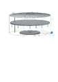
Изобретение поясняется графически, где на фигуре изображен общий вид комплексной системы обеспечения целостности резервуара (КСОЦР). Позициями на фигуре обозначены:The invention is illustrated graphically, where the figure shows a general view of the integrated system for ensuring the integrity of the tank (KSOTSR). The positions on the figure are:
1 - резервуар для хранения нефти и нефтепродуктов;1 - tank for storing oil and oil products;
2 - компенсатор взрыва;2 - explosion compensator;
3 - трубопровод;3 - pipeline;
4 - баллонная система с инертным газом;4 - balloon system with inert gas;
5 - стенка компенсатора взрыва;5 - wall of the explosion compensator;
6 - ослабленный сварной шов;6 - weakened weld;
7 - опоры.7 - supports.
Комплексная система обеспечения целостности резервуара для хранения нефти и нефтепродуктов (1) включает компенсатор взрыва (2), баллонную систему с инертным газом (4) и трубопровод (3), соединяющий компенсатор взрыва (2) и баллонную систему с инертным газом (4).The integrated system for ensuring the integrity of a tank for storing oil and oil products (1) includes an explosion compensator (2), an inert gas cylinder system (4) and a pipeline (3) connecting the explosion compensator (2) and an inert gas cylinder system (4).
Компенсатор взрыва (2) представляет собой цилиндр, заполненный находящимся под давлением сжиженным инертным газом, например, азотом или гелием, сжатым до полного объема резервуара, т.е. до такой степени, чтобы при выпуске газа из компенсатора объем газа позволил заполнить фактический объем резервуара, находящегося без нефти/нефтепродуктов.The explosion compensator (2) is a cylinder filled with a pressurized liquefied inert gas, such as nitrogen or helium, compressed to the full volume of the tank, i.e. to such an extent that when the gas is released from the compensator, the volume of gas allows filling the actual volume of the reservoir, which is without oil / oil products.
Компенсатор может быть металлическим или из композитного материала. В соответствии с требованиями ГОСТ 31385-2016 «Межгосударственный стандарт. Резервуары вертикальные цилиндрические стальные для нефти и нефтепродуктов. Общие технические условия» стали, используемые для изготовления конструкций резервуаров, должны соответствовать требованиям действующих стандартов и ТУ, а также требованиям проектной документации. Выбор марки стали компенсатора взрыва (2) проводится под конкретный резервуар, эксплуатируемый организацией, с учетом гарантированного минимального предела текучести, толщины проката и хладостойкости (ударной вязкости). Рекомендуемые марки стали приведены в приложении А ГОСТ 31385-2016.The compensator can be metal or composite material. In accordance with the requirements of GOST 31385-2016 “Interstate standard. Tanks vertical cylindrical steel for oil and oil products. General Specifications” of steel used for the manufacture of tank structures must comply with the requirements of applicable standards and specifications, as well as the requirements of project documentation. The choice of the steel grade of the explosion compensator (2) is carried out for a specific tank operated by the organization, taking into account the guaranteed minimum yield strength, rolled thickness and cold resistance (impact strength). Recommended steel grades are given in Annex A of GOST 31385-2016.
Геометрические размеры компенсатора взрыва (2) выбираются индивидуально для каждого резервуара для хранения нефти и нефтепродуктов (1), в зависимости от его объема и исходя из расчета необходимого количества флегматизатора (инертного газа) - негорючего газа, введение которого в горючую смесь сужает область воспламенения или полностью устраняет возможность горения.The geometric dimensions of the explosion compensator (2) are selected individually for each tank for storing oil and oil products (1), depending on its volume and based on the calculation of the required amount of a phlegmatizer (inert gas) - a non-combustible gas, the introduction of which into a combustible mixture narrows the area of ignition or completely eliminates the possibility of burning.
К примеру, при диаметре резервуара вертикального стального с крышей и понтоном (РВСП) объемом 20000 м3, составляющим ≈45,6 м, диаметр компенсатора взрыва (2) составит ≈35,2 м, высота компенсатора взрыва при этом будет выбираться в зависимости от давления внутри компенсатора взрыва (2):For example, if the diameter of a vertical steel tank with a roof and a pontoon (RVSP) with a volume of 20,000 m 3 is ≈45.6 m, the diameter of the explosion compensator (2) will be ≈35.2 m, the height of the explosion compensator will be selected depending on pressure inside the explosion compensator (2):
- от 1,39 м при давлении 3 МПа;- from 1.39 m at a pressure of 3 MPa;
- до 0,83 м при давлении 5 МПа.- up to 0.83 m at a pressure of 5 MPa.
Объем флегматизатора (инертного газа), находящегося в компенсаторе, для данного примера будет соответствовать объему резервуара 20000 м3 в количестве сжатого азота от 800 м3 при давлении 5 МПа до 1350 м3 при давлении 3 МПа. Давление инертного газа в компенсаторе взрыва (2) не должно превышать порогового значения разрыва ослабленного сварного шва (6), в данном примере - 5 МПа.The volume of the phlegmatizer (inert gas) located in the compensator for this example will correspond to the volume of the tank 20,000 m 3 in the amount of compressed nitrogen from 800 m 3 at a pressure of 5 MPa to 1350 m 3 at a pressure of 3 MPa. The pressure of the inert gas in the explosion compensator (2) must not exceed the threshold value of the rupture of the weakened weld (6), in this example 5 MPa.
Верхняя и нижняя (днище) части компенсатора взрыва (2) выполняются в виде металлической радиально-кольцевой листовой каркасно-секционной системы. Между ними расположена стенка компенсатора взрыва (5).The upper and lower (bottom) parts of the explosion compensator (2) are made in the form of a metal radial-annular sheet frame-sectional system. Between them is the wall of the explosion compensator (5).
В стенке компенсатора взрыва (5) выполнен ослабленный сварной шов (6) - самораскрывающееся сварное соединение, целью которого является мгновенный выпуск инертного газа посредством разрушения сварного шва давлением ударной волны, образующейся при взрыве газо-воздушной смеси в резервуаре для хранения нефти и нефтепродуктов (1).A weakened weld (6) is made in the wall of the explosion compensator (5) - a self-opening welded joint, the purpose of which is the instantaneous release of inert gas by destroying the weld by the pressure of the shock wave generated during the explosion of the gas-air mixture in the tank for storing oil and oil products (1 ).
Предпочтительно, если ослабленный сварной шов (6) будет выполнен круговым и расположен по центру стенки компенсатора взрыва (5), что позволит инертному газу лучше и быстрее распределиться в резервуаре за счет мгновенного раскрытия компенсатора взрыва (2), при воздействии на компенсатор давления ударной волны, образующейся при взрыве газовоздушной смеси в резервуаре.It is preferable if the weakened weld (6) is made circular and located in the center of the wall of the explosion compensator (5), which will allow the inert gas to be better and faster distributed in the tank due to the instantaneous opening of the explosion compensator (2), when the shock wave is applied to the compensator formed during the explosion of the gas-air mixture in the tank.
Компенсатор взрыва (2) жестко устанавливается на днище резервуара путем сварки стенки (5) компенсатора с днищем резервуара (1).The explosion compensator (2) is rigidly mounted on the tank bottom by welding the wall (5) of the compensator with the tank bottom (1).
Трубопровод (3) предназначен для поддержания и регулирования давления инертного газа, находящегося в компенсаторе взрыва (2). Трубопровод (3) выходит из компенсатора взрыва (5), проходит через стенку первого пояса резервуара (1) и подсоединяется к баллонной системе с инертным газом (4). Трубопровод (3) располагается на металлических опорах (7), приваренных к днищу резервуара (1). В целях исключения искрообразования предпочтительно, чтобы трубопровод (3) был выполнен из меди.The pipeline (3) is designed to maintain and regulate the pressure of the inert gas in the explosion compensator (2). The pipeline (3) exits the explosion compensator (5), passes through the wall of the first belt of the tank (1) and is connected to the inert gas cylinder system (4). The pipeline (3) is located on metal supports (7) welded to the bottom of the tank (1). In order to avoid sparking, it is preferable that the pipeline (3) is made of copper.
Баллонная система с инертным газом (4) предназначена для поддержания и регулирования давления инертного газа, находящегося в компенсаторе взрыва (2), а также для подачи инертного газа по факту взрыва в резервуаре (1). Баллонная система с инертным газом (4) включает по меньшей мере два баллона (основной и резервный) с манометрами и редукторами и систему автоматики, позволяющую передавать текущие показания манометров на автоматизированное рабочее место оператора посредством беспроводной передачи данных. Баллонная система с инертным газом (4) располагается за пределами резервуара (1), предпочтительно в шкафу для укрытия и ограничения доступа к автоматике.The balloon system with inert gas (4) is designed to maintain and regulate the pressure of inert gas in the explosion compensator (2), as well as to supply inert gas in the tank (1) upon explosion. Inert gas cylinder system (4) includes at least two cylinders (main and reserve) with pressure gauges and reducers and an automation system that allows the current pressure gauge readings to be transmitted to the operator's automated workplace via wireless data transmission. The inert gas cylinder system (4) is located outside the tank (1), preferably in a closet to hide and restrict access to the automation.
Сущность изобретения заключается в том, что в соответствии с законом Паскаля (закон гидростатики), при взрыве в резервуаре паров нефти или нефтепродукта давление, создаваемое взрывом на поверхность жидкости, передается жидкостью одинаково во всех направлениях. Жестко приваренный к днищу резервуара (1) компенсатор взрыва (2) при взрыве топливно-воздушной смеси (ТВС) в резервуаре (1), поглощает давление (ударную волну) созданную взрывом, тем самым снижая создаваемое взрывом давление до значений, безопасных для уторного шва, предотвращая деформацию днища резервуара и уменьшая его максимальный подъем, сохраняя при этом конструктивную целостность резервуара.The essence of the invention lies in the fact that, in accordance with Pascal's law (the law of hydrostatics), during an explosion in an oil or oil product vapor reservoir, the pressure created by the explosion on the liquid surface is transferred by the liquid equally in all directions. An explosion compensator (2) rigidly welded to the bottom of the tank (1) during the explosion of the fuel-air mixture (FA) in the tank (1), absorbs the pressure (shock wave) created by the explosion, thereby reducing the pressure created by the explosion to values that are safe for the folded seam , preventing deformation of the tank bottom and reducing its maximum lift, while maintaining the structural integrity of the tank.
Комплексная система обеспечения целостности резервуара работает следующим образом.The integrated reservoir integrity system operates as follows.
Избыточное давленое, при котором происходит отрыв уторного шва превышает испытательное давление резервуара на Δ 4,0 кПА. Таким образом, избыточного давленое, при котором должен срабатывать компенсатор взрыва (2), т.е. разрушаться ослабленный сварной шов (6) должно превышать испытательное давление резервуара на Δ 3,5 кПА.The overpressure at which the morning seam is torn off exceeds the test pressure of the tank by Δ 4.0 kPa. Thus, the excess pressure at which the explosion compensator (2) must operate, i.e. the weakened weld (6) should fail to exceed the test pressure of the tank by Δ 3.5 kPa.
Компенсатор взрыва (2) содержит находящийся под давлением сжиженный инертный газ, например, азот или гелий, сжатый до полного объема резервуара, т.е. в объеме, позволяющем инертному газу заполнить фактический объем резервуара, находящегося без нефти/нефтепродуктов после его выхода из компенсатора взрыва (2). Наполнение и регулирование давления инертного газа, находящегося в компенсаторе взрыва (2), осуществляется посредством баллонной системы с инертным газом (4), расположенной с наружной стороны резервуара, предпочтительно в шкафу, оснащенной редуктором. Показатели давления инертного газа, находящегося в компенсаторе взрыва (2), передаются на автоматизированное рабочее место оператора посредством манометров, оборудованных устройством дистанционной передачи данных.The explosion compensator (2) contains a pressurized liquefied inert gas, such as nitrogen or helium, compressed to the full volume of the tank, i.e. in a volume that allows the inert gas to fill the actual volume of the tank, which is without oil / oil products after it leaves the explosion compensator (2). Filling and pressure regulation of the inert gas in the explosion compensator (2) is carried out by means of an inert gas cylinder system (4) located on the outside of the tank, preferably in a cabinet equipped with a reducer. The pressure readings of the inert gas in the explosion compensator (2) are transmitted to the operator's workstation by means of pressure gauges equipped with a remote data transmission device.
В случае взрыва ТВС предусмотренный на стенке компенсатора взрыва (5) ослабленный сварной шов (6) при воздействии на него давления взрыва газо-воздушной смеси (ударной волны) разрушается, высвобождая находящийся в компенсаторе взрыва (2) инертный газ. Вместе с разрушением компенсатора взрыва (2) происходит перекрытие дыхательных патрубков резервуара, а также закрытие аварийных и дыхательных клапанов (при их наличии), благодаря чему исключается поступление кислорода внутрь резервуара. Высвободившийся из компенсатора взрыва (2) инертный газ разбавляет ТВС через зазор между понтоном или плавающей крышей и стенкой резервуара (1), уменьшая концентрацию имеющегося в резервуаре кислорода. При этом входящая в комплексную систему обеспечения целостности резевуара баллонная система с инертным газом (4) продолжает подачу инертного газа в резервуар. Происходит процесс флегматизации, результатом которого является уменьшение области воспламенения или полное устранение возможности горения ТВС внутри резервуара.In the event of an explosion of fuel assemblies, the weakened weld (6) provided on the wall of the explosion compensator (5), when exposed to the explosion pressure of the gas-air mixture (shock wave), is destroyed, releasing the inert gas in the explosion compensator (2). Together with the destruction of the explosion compensator (2), the breathing pipes of the tank are blocked, as well as the emergency and breathing valves (if any) are closed, which prevents the flow of oxygen into the tank. The inert gas released from the explosion compensator (2) dilutes the fuel assembly through the gap between the pontoon or floating roof and the tank wall (1), reducing the concentration of oxygen present in the tank. At the same time, the inert gas cylinder system (4), which is part of the integrated system for ensuring the integrity of the tank, continues to supply inert gas to the tank. The process of phlegmatization occurs, the result of which is a reduction in the area of ignition or the complete elimination of the possibility of combustion of fuel assemblies inside the tank.
Заявленное изобретение обеспечивает комплексный подход к предотвращению и тушению пожаров в резервуарах, позволяющий при взрыве паров нефти или нефтепродукта в наземном металлическом резервуаре снизить давление в нем до значений, безопасных для уторного шва, тем самым сохранив конструктивную целостность резервуара, а также устранить возгорание за счет понижения концентрации кислорода путем разбавления топливно-воздушной смеси (ТВС), инертным газом (азотом/гелием). Достоинство заявленного изобретения заключается в том, что заявленная комплексная система обеспечения целостности резервуара не может потерять работоспособность вследствие взрыва внутри резервуара и избыточного давления продуктов взрыва, поскольку взрыв требуется для ее активации, что повышает надежность работы системы и, как следствие, безопасность эксплуатации резервуара. Конструкция системы предусматривает мгновенный выпуск инертного газа из компенсатора взрыва, расположенного на днище резервуара, в объеме, сжатом до полного объема резервуара, что обеспечивает своевременное уменьшение концентрации кислорода («разбавление») внутри резервуара и купирование пожара, благодаря чему повышается эффективность работы системы пожаротушения и прекращается возгорание.The claimed invention provides a comprehensive approach to the prevention and extinguishing of fires in tanks, which allows, in the event of an explosion of oil or oil product vapors in a ground metal tank, to reduce the pressure in it to values that are safe for the morning seam, thereby maintaining the structural integrity of the tank, and also to eliminate fire by lowering oxygen concentration by diluting the fuel-air mixture (FA) with an inert gas (nitrogen / helium). The advantage of the claimed invention lies in the fact that the claimed integrated system for ensuring the integrity of the tank cannot lose its operability due to an explosion inside the tank and excessive pressure of the explosion products, since an explosion is required to activate it, which increases the reliability of the system and, as a result, the safety of the tank operation. The design of the system provides for the instantaneous release of inert gas from the explosion compensator located at the bottom of the tank in a volume compressed to the full volume of the tank, which ensures a timely decrease in the oxygen concentration (“dilution”) inside the tank and suppression of the fire, thereby increasing the efficiency of the fire extinguishing system and the fire stops.
Claims (9)
Publications (1)
| Publication Number | Publication Date |
|---|---|
| RU2773473C1 true RU2773473C1 (en) | 2022-06-06 |
Family
ID=
Citations (6)
| Publication number | Priority date | Publication date | Assignee | Title |
|---|---|---|---|---|
| US3878897A (en) * | 1972-09-25 | 1975-04-22 | P R B Societe Anonyme Sa | Process and device for creating triggered stop barriers in mines and in various underground works |
| US4655242A (en) * | 1980-03-28 | 1987-04-07 | Jgc Corporation | Water seal drum |
| US6409779B2 (en) * | 1998-04-25 | 2002-06-25 | Leinemann Gmbh & Co. | Method for rendering a detonation front harmless |
| RU2425702C1 (en) * | 2010-05-19 | 2011-08-10 | Закрытое акционерное общество "Научно-производственное объединение Вариант-Гидротехника" (ЗАО "НПО Вариант-Гидротехника") | Method of fire protection of reservoirs for storage of liquid combustibles and device for its realisation |
| RU170678U1 (en) * | 2016-04-15 | 2017-05-03 | Федеральное государственное автономное образовательное учреждение высшего образования "Сибирский федеральный университет" | FIRE RESISTANCE EQUIPMENT FOR OIL PRODUCT RESERVOIR |
| RU2659981C1 (en) * | 2017-08-14 | 2018-07-04 | Публичное акционерное общество "Транснефть" (ПАО "Транснефть") | Method of protecting fire extinguishing system pipelines and water cooling of tanks for oil and oil products against effect of gas-air mixture explosion |
Patent Citations (6)
| Publication number | Priority date | Publication date | Assignee | Title |
|---|---|---|---|---|
| US3878897A (en) * | 1972-09-25 | 1975-04-22 | P R B Societe Anonyme Sa | Process and device for creating triggered stop barriers in mines and in various underground works |
| US4655242A (en) * | 1980-03-28 | 1987-04-07 | Jgc Corporation | Water seal drum |
| US6409779B2 (en) * | 1998-04-25 | 2002-06-25 | Leinemann Gmbh & Co. | Method for rendering a detonation front harmless |
| RU2425702C1 (en) * | 2010-05-19 | 2011-08-10 | Закрытое акционерное общество "Научно-производственное объединение Вариант-Гидротехника" (ЗАО "НПО Вариант-Гидротехника") | Method of fire protection of reservoirs for storage of liquid combustibles and device for its realisation |
| RU170678U1 (en) * | 2016-04-15 | 2017-05-03 | Федеральное государственное автономное образовательное учреждение высшего образования "Сибирский федеральный университет" | FIRE RESISTANCE EQUIPMENT FOR OIL PRODUCT RESERVOIR |
| RU2659981C1 (en) * | 2017-08-14 | 2018-07-04 | Публичное акционерное общество "Транснефть" (ПАО "Транснефть") | Method of protecting fire extinguishing system pipelines and water cooling of tanks for oil and oil products against effect of gas-air mixture explosion |
Similar Documents
| Publication | Publication Date | Title |
|---|---|---|
| EP1534394B1 (en) | Automatic foam fire fighting equipment especially used as fixed installation equipment for fire fighting of large hydrocarbon storage tanks | |
| JP2013141584A (en) | Explosion suppression equipment | |
| US10099077B2 (en) | Installed fire fighting apparatus for flammable objects | |
| CN115591152A (en) | Remote gas fire extinguishing and explosion suppression system applied to open space and application method thereof | |
| RU2773473C1 (en) | Integrated tank integrity system | |
| RU2757479C1 (en) | Method for fire and explosion prevention and fire extinguishing with hybrid foam and device for its implementation | |
| CN114387835B (en) | Drill equipment for presenting fire and explosion scenarios and method for performing emergency drills | |
| Ubowska et al. | Engine rooms fire safety–fire-extinguishing system requirements | |
| JP2000140142A (en) | Fire extinguishing device for floating roof tank | |
| CN108980612B (en) | A combustible gas explosion inerting suppression method and its device | |
| Söderholm | Fire Safety in Hydrogen Processing Facilities-Design Considerations | |
| RU203044U1 (en) | Nozzles with foam generators for auto-mechanical fire escape | |
| RU2751894C1 (en) | Nozzle with foam generators for automotive fire escape | |
| RU2851727C1 (en) | System for supplying inhibitor to prevent ignition and explosion of hydrogen-air mixtures in hydrogen transport pipeline | |
| JP5527660B2 (en) | Fire extinguishing and fire prevention methods for flammable and flammable liquid storage tanks | |
| Suwa | Studies on the safe application techniques of high-pressure hydrogen gas | |
| JP2016096920A (en) | Fire protection/firefighting equipment and method of flammable or combustible liquid storage tank | |
| Omidvar et al. | Fire event in oil, gas, and petrochemical industries | |
| RU2804950C1 (en) | Method for fire and explosion prevention and extinguishing large-scale transport emergency and industrial emergency fires with combined hybrid foam and device for its implementation | |
| RU145711U1 (en) | INSTALLATION OF EXTINGUISHING OIL PRODUCTS IN TANKS OF LARGE CAPACITY WITH APPLICATION OF THE COMBINED FIRE EXTINGUISHING MIXTURE | |
| KR100493523B1 (en) | Arclamp flamethrower with waterproof, explosion proof and warning function | |
| Olivo | Loss prevention in a modern ethylene plant | |
| CN121944447A (en) | A shipboard fire prevention and safe hatch opening system and method based on continuous external supply | |
| KR20250001845U (en) | Automatic Fire Extinguishing Device for Wildfire | |
| CN106362327B (en) | Vault jar with fire control facility |