RU2777075C1 - Gripping tool and method for using a gripping tool - Google Patents
Gripping tool and method for using a gripping tool Download PDFInfo
- Publication number
- RU2777075C1 RU2777075C1 RU2021129028A RU2021129028A RU2777075C1 RU 2777075 C1 RU2777075 C1 RU 2777075C1 RU 2021129028 A RU2021129028 A RU 2021129028A RU 2021129028 A RU2021129028 A RU 2021129028A RU 2777075 C1 RU2777075 C1 RU 2777075C1
- Authority
- RU
- Russia
- Prior art keywords
- gripping
- gripping part
- relative
- rotation
- operating
- Prior art date
Links
- 238000000034 method Methods 0.000 title claims abstract description 30
- 230000007246 mechanism Effects 0.000 claims abstract description 54
- 230000000694 effects Effects 0.000 abstract description 3
- 239000000126 substance Substances 0.000 abstract 1
- 230000000903 blocking effect Effects 0.000 description 5
- 230000004044 response Effects 0.000 description 5
- 230000009467 reduction Effects 0.000 description 3
- 230000005540 biological transmission Effects 0.000 description 2
- 230000009471 action Effects 0.000 description 1
- 230000008859 change Effects 0.000 description 1
- 239000004020 conductor Substances 0.000 description 1
- 239000000463 material Substances 0.000 description 1
- 238000000926 separation method Methods 0.000 description 1
- 230000007704 transition Effects 0.000 description 1
Images


Abstract
Description
Область техникиTechnical field
Изобретение относится к захватывающему инструменту и способу применения этого захватывающего инструмента.The invention relates to a gripping tool and a method of using this gripping tool.
Предшествующий уровень техникиPrior Art
Захватывающие инструменты, которые захватывают захватываемый объект являются известными.Grasping tools that grip the object to be gripped are known.
В качестве предшествующего уровня техники патентный документ JP2015165739 (далее – Патентный документ 1) раскрывает инструмент для непрямого активного захвата провода. Инструмент для непрямого активного захвата провода, раскрытый в Патентном документе 1, имеет захватывающий механизм, изолирующий рабочий стержень, ответный элемент и блокирующий механизм. Захватывающий механизм имеет фиксированную захватывающую часть и подвижную захватывающую часть. Изолирующий рабочий стержень имеет корпус рабочего стержня и элемент стороны сердечника вала, расположенный внутри корпуса рабочего стержня. Корпус рабочего штока выполнен с возможностью осевого скольжения относительно элемента стороны сердечника вала.As a prior art, patent document JP2015165739 (hereinafter referred to as Patent Document 1) discloses a tool for indirect active wire gripping. The indirect active wire gripping tool disclosed in
В инструменте для непрямого активного захвата провода, описанном в Патентном документе 1, в ответ на то, что корпус рабочего стержня скользит к стороне захватывающего механизма, приводится в действие блокирующий механизм. Состояние приведения в действие блокирующего механизма предотвращает вращение изолирующего рабочего стержня, в результате чего подвижная захватывающая часть перемещается в направлении от фиксированной захватывающей части. В ответ на скольжение корпуса рабочего стержня в направлении от захватывающего механизма блокирующий механизм разблокируется. В результате возможно поворачивать изолирующий рабочий стержень так, чтобы подвижная захватывающая часть перемещалась в направлении от фиксированной захватывающей части.In the indirect active wire gripping tool described in
Раскрытие изобретенияDisclosure of invention
Техническая проблемаTechnical problem
Задачей изобретения является создание захватывающего инструмента, который можно переключать между заблокированным состоянием и разблокированным состоянием с помощью простой операции, и создание способа применения захватывающего инструмента.The object of the invention is to provide a gripping tool that can be switched between a locked state and an unlocked state with a simple operation, and to provide a method for using the gripping tool.
Решение проблемыSolution
Изобретение относится к захватывающему инструменту и способу применения захватывающего инструмента, описанным далее.The invention relates to a gripping tool and a method of using a gripping tool, as described below.
(1) Захватывающий инструмент, содержащий:(1) A gripping tool, comprising:
первый элемент, включающий в себя первую захватывающую часть;the first element, including the first exciting part;
второй элемент, включающий в себя вторую захватывающую часть;a second element including a second gripping portion;
рабочий элемент, способный вызывать перемещение второй захватывающей части относительно первой захватывающей части в направлении, параллельном первому направлению, когда направление от второй захватывающей части к первой захватывающей части определено как первое направление, а направление, противоположное первому направлению, определено как второе направление;an operating element capable of causing movement of the second gripping part relative to the first gripping part in a direction parallel to the first direction, when the direction from the second gripping part to the first gripping part is defined as the first direction, and the direction opposite to the first direction is defined as the second direction;
третий элемент, ввинченный в рабочий элемент и навинченный на второй элемент; иa third element screwed into the working element and screwed onto the second element; and
блокирующий механизм, приспособленный для выполнения переключения между заблокированным состоянием для предотвращения перемещения второй захватывающей части относительно первой захватывающей части во втором направлении и разблокированным состоянием для обеспечения перемещения второй захватывающей части относительно первой захватывающей части во втором направлении,a locking mechanism adapted to switch between a locked state to prevent movement of the second gripping part relative to the first gripping part in the second direction and an unlocked state to allow movement of the second gripping part relative to the first gripping part in the second direction,
при этом блокирующий механизм включает в себя участок зацепления, выполненный в третьем элементе.wherein the locking mechanism includes an engagement portion provided in the third element.
(2) Захватывающий инструмент по п. (1) выше, выполненный так, что вращение рабочего элемента в первом направлении вращения вызывает как перемещение второй захватывающей части в первом направлении, так и переключение из разблокированного состояния в заблокированное состояние.(2) The gripping tool according to (1) above, configured such that rotation of the operating member in the first direction of rotation causes both movement of the second gripping portion in the first direction and switching from an unlocked state to a locked state.
(3) Захватывающий инструмент по п. (1) или (2) выше, выполненный так, что заблокированное состояние сохраняется до тех пор, пока рабочий элемент не повернется на предварительно заданный угол во втором направлении вращения, и переключение из заблокированного состояния в разблокированное состояние выполняется, когда рабочий элемент вращается на предварительно заданный угол или больше во втором направлении вращения.(3) The gripping tool according to (1) or (2) above, configured such that the locked state is maintained until the work member rotates a predetermined angle in the second rotation direction, and switching from the locked state to the unlocked state is executed when the work item is rotated by a predetermined angle or more in the second direction of rotation.
(4) Захватывающий инструмент по любому из пп. (1) – (3) выше, в котором третий элемент содержит:(4) A gripping tool according to any one of paragraphs. (1) - (3) above, in which the third element contains:
первую поверхность, определяющую верхнее предельное положение рабочего элемента относительно третьего элемента; иthe first surface defining the upper limit position of the working element relative to the third element; and
вторую поверхность, определяющую нижнее предельное положение рабочего элемента относительно третьего элемента.the second surface defining the lower limit position of the working element relative to the third element.
(5) Захватывающий инструмент по любому из пп. (1) – (4) выше, в котором блокирующий механизм включает в себя второй участок зацепления, выполненный в первом элементе.(5) A gripping tool according to any one of paragraphs. (1) to (4) above, wherein the locking mechanism includes a second engagement portion provided in the first member.
(6) Захватывающий инструмент по любому из пп. (1) – (5) выше, в котором рабочий элемент содержит прижимающую часть, которая переключает состояние блокирующего механизма из заблокированного состояния в разблокированное состояние.(6) A gripping tool according to any one of paragraphs. (1) - (5) above, in which the operating element contains a pressing part that switches the state of the locking mechanism from a locked state to an unlocked state.
(7) Захватывающий инструмент по любому из пп. (1) – (6) выше, в котором рабочий элемент содержит крепежную часть, к которой с возможностью отсоединения прикреплен стержень дистанционного управления.(7) A gripping tool according to any one of paragraphs. (1) - (6) above, in which the operating element contains a fastening part, to which the remote control rod is detachably attached.
(8) Способ применения захватывающего инструмента, содержащего:(8) A method of using a gripping tool, comprising:
первый элемент, включающий в себя первую захватывающую часть;the first element, including the first exciting part;
второй элемент, включающий в себя вторую захватывающую часть;a second element including a second gripping portion;
рабочий элемент, способный вызывать перемещение второй захватывающей части относительно первой захватывающей части в направлении, параллельном первому направлению, когда направление от второй захватывающей части к первой захватывающей части определено как первое направление, а направление, противоположное первому направлению, определено как второе направление;an operating element capable of causing movement of the second gripping part relative to the first gripping part in a direction parallel to the first direction, when the direction from the second gripping part to the first gripping part is defined as the first direction, and the direction opposite to the first direction is defined as the second direction;
третий элемент, ввинченный в рабочий элемент и навинченный на второй элемент; иa third element screwed into the working element and screwed onto the second element; and
блокирующий механизм, приспособленный для выполнения переключения между заблокированным состоянием для предотвращения перемещения второй захватывающей части относительно первой захватывающей части во втором направлении и разблокированным состоянием для обеспечения перемещения второй захватывающей части относительно первой захватывающей части во втором направлении,a locking mechanism adapted to switch between a locked state to prevent movement of the second gripping part relative to the first gripping part in the second direction and an unlocked state to allow movement of the second gripping part relative to the first gripping part in the second direction,
причем способ включает в себя:wherein the method includes:
этап, на котором размещают захватываемый объект между первой захватывающей частью и второй захватывающей частью; иa step of placing a gripping object between the first gripping part and the second gripping part; and
этап захвата, на котором захватываемый объект захватывают первой захватывающей частью и второй захватывающей частью посредством вращения рабочего элемента в первом направлении вращения,a gripping step in which the object to be gripped is gripped by the first gripping part and the second gripping part by rotating the operating element in the first rotation direction,
при этом этап захвата включает в себя:while the capture stage includes:
этап уменьшения расстояния, на котором уменьшают расстояние между первой захватывающей частью и второй захватывающей частью посредством относительного вращения между третьим элементом и вторым элементом, иa distance reducing step in which the distance between the first gripping part and the second gripping part is reduced by a relative rotation between the third element and the second element, and
первый этап переключения, на котором переключают состояние блокирующего механизма из разблокированного состояния в заблокированное состояние посредством относительного вращения между третьим элементом и рабочим элементом.a first switching step in which the state of the locking mechanism is switched from an unlocked state to a locked state by relative rotation between the third element and the operating element.
(9) Способ применения захватывающего инструмента по п. (8) выше, дополнительно включающий в себя:(9) The method of using the gripping tool according to (8) above, further comprising:
этап освобождения захвата, на котором освобождают захват объекта, захваченного первой захватывающей частью и второй захватывающей частью,a grip releasing step of releasing the grip of the object gripped by the first gripping part and the second gripping part,
при этом этап освобождения захвата включает в себя:wherein the step of releasing the grip includes:
второй этап переключения, на котором переключают состояние блокирующего механизма из заблокированного состояния в разблокированное состояние посредством относительного вращения между третьим элементом и рабочим элементом, иa second switching step that switches the state of the locking mechanism from a locked state to an unlocked state by relative rotation between the third element and the operating element, and
этап увеличения расстояния, на котором увеличивают расстояние между первой захватывающей частью и второй захватывающей частью посредством относительного вращения между третьим элементом и вторым элементом.a distance increasing step in which the distance between the first gripping part and the second gripping part is increased by relative rotation between the third element and the second element.
Преимущественный эффект изобретенияPreferential effect of the invention
Согласно изобретению можно создать захватывающий инструмент, который может переключаться между заблокированным состоянием и разблокированным состоянием с помощью простой операции, и создать способ применения захватывающего инструмента.According to the invention, it is possible to provide a gripping tool that can switch between a locked state and an unlocked state with a simple operation, and provide a method for using the gripping tool.
Краткое описание чертежейBrief description of the drawings
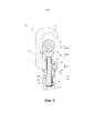
На фиг. 1 схематично показан захватывающий инструмент в первом варианте осуществления изобретения, общий вид в вертикальном разрезе;In FIG. 1 schematically shows a gripping tool in a first embodiment of the invention, in a general view in vertical section;
на фиг. 2 – захватывающий инструмент в первом варианте осуществления изобретения, общий вид сбоку;in fig. 2 - gripping tool in the first embodiment of the invention, general side view;
на фиг. 3 – захватывающий инструмент в первом варианте осуществления изобретения, общий вид в вертикальном разрезе;in fig. 3 - gripping tool in the first embodiment of the invention, general view in vertical section;
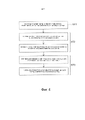
на фиг. 4 показана блок-схема, поясняющая пример способа применения захватывающего инструмента в первом варианте осуществления изобретения;in fig. 4 is a flowchart for explaining an example of the method of using the picking tool in the first embodiment of the invention;
на фиг. 5 схематично показано состояние, в котором выполняется один этап способа применения захватывающего инструмента, общий вид в вертикальном разрезе;in fig. 5 is a schematic view showing a state in which one step of the picking tool application method is performed, taken as a general view in vertical section;
на фиг. 6 – состояние, в котором выполняется один этап способа применения захватывающего инструмента, общий вид в вертикальном разрезе;in fig. 6 is a state in which one step of the gripping tool application method is performed, a general view in a vertical section;
на фиг. 7 – состояние, в котором выполняется один этап способа применения захватывающего инструмента, общий вид в вертикальном разрезе;in fig. 7 is a state in which one step of the gripping tool application method is performed, a general view in a vertical section;
на фиг. 8 – состояние, в котором выполняется один этап способа применения захватывающего инструмента, общий вид в вертикальном разрезе;in fig. 8 is a state in which one step of the gripping tool application method is performed, a general view in a vertical section;
на фиг. 9 – состояние, в котором выполняется один этап способа применения захватывающего инструмента, общий вид в вертикальном разрезе;in fig. 9 is the state in which one step of the gripping tool application method is performed, general view in vertical section;
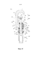
на фиг. 10 – захватывающий инструмент во втором варианте осуществления изобретения, общий вид сзади.in fig. 10 is a gripping tool in the second embodiment of the invention, a general rear view.
на фиг. 11 – вид в разрезе по плоскости A-A на фиг. 10.in fig. 11 is a sectional view along plane A-A in FIG. ten.
Варианты осуществления изобретенияEmbodiments of the invention
Инструмент 1 для захвата и способ применения захватывающего инструмента в вариантах осуществления будут подробно описаны далее со ссылками на чертежи. Следует обратить внимание, что в этом описании элементы, имеющие один и тот же тип функций, помечены одинаковыми или подобными ссылочными позициями. Кроме того, для элементов, помеченных одинаковыми или подобными ссылочными позициями, их дублированное описание может быть опущено.The
Определение направленийDefinition of directions
В этом описании направление от второй захватывающей части 21 (более конкретно, второй захватывающей поверхности 21a) к первой захватывающей части 11 (более конкретно, первой захватывающей поверхности 11a) определяется как первое направление DR1, а направление, противоположное первому направлению DR1 определяется как второе направление DR2.In this description, the direction from the second gripping part 21 (more specifically, the second
Первый вариант осуществления изобретенияFirst embodiment of the invention
Захватывающий инструмент 1A в первом варианте осуществления изобретения будет описан со ссылкой на фиг. 1 – фиг. 3. Фиг. 1 и фиг. 3 представляют собой общие виды в вертикальном разрезе, схематично поясняющие захватывающий инструмент 1А в первом варианте осуществления. Фиг. 2 представляет собой общий вид сбоку, схематично поясняющий захватывающий инструмент 1А в первом варианте осуществления.The
Захватывающий инструмент 1A имеет первый элемент 10, второй элемент 20, третий элемент 30, рабочий элемент 40 и блокирующий механизм M.The
В примере, представленном на фиг. 1, первый элемент 10 включает в себя первую захватывающую часть 11. Кроме того, в примере, представленном на фиг. 1, первый элемент 10 является конструктивным элементом, имеющим проём OP, который принимает захватываемый объект. Хотя первый элемент 10 является элементом, имеющим, по существу, С-образную форму на виде сбоку в примере, представленном на фиг. 1 и фиг. 2, форма первого элемента 10 не ограничивается примером, представленным на фиг. 1 и фиг. 2. Следует обратить внимание, что первый элемент 10 может быть сформирован из одного компонента или может быть сформирован из узла из множества компонентов.In the example shown in FIG. 1, the
В примере, представленном на фиг. 1, первая захватывающая часть 11 имеет первую захватывающую поверхность 11a, которая входит в контакт с захватываемым объектом. Первая захватывающая поверхность 11а представляет собой, например, изогнутую поверхность.In the example shown in FIG. 1, the first
В примере, представленном на фиг. 1, второй элемент 20 включает в себя вторую захватывающую часть 21. Второй элемент 20 является элементом, который может перемещаться относительно первого элемента 10. В примере, представленном на фиг. 1, второй элемент 20 имеет резьбовой стержень 23 в дополнение ко второй захватывающей части 21. В примере, представленном на фиг. 1, резьбовой стержень 23 имеет часть 23m с внешней резьбой на своей внешней окружной поверхности. В примере, представленном на фиг. 1, второй элемент 20 сформирован из узла, состоящего из компонента, образующего вторую захватывающую часть 21, и компонента, образующего резьбовой стержень 23. В качестве альтернативы, второй элемент 20 может быть сформирован из одного компонента или может быть сформирован из узла из трех или более компонентов.In the example shown in FIG. 1, the
В примере, представленном на фиг. 1, вторая захватывающая часть 21 имеет вторую захватывающую поверхность 21а, которая входит в контакт с захватываемым объектом. Вторая захватывающая поверхность 21а представляет собой, например, изогнутую поверхность.In the example shown in FIG. 1, the second gripping
Рабочий элемент 40 является элементом, который вызывает перемещение второй захватывающей части 21 относительно первой захватывающей части 11 в направлении, параллельном первому направлению DR1.The operating
Когда рабочий элемент 40 приводится в действие, расстояние между первой захватывающей частью 11 (более конкретно, первой захватывающей поверхностью 11a) и второй захватывающей частью 21 (более конкретно, второй захватывающей поверхностью 21a) изменяется. В примере, представленном на фиг. 1, когда рабочий элемент 40 вращается в первом направлении R1 вращения, вторая захватывающая часть 21 перемещается в направлении к первой захватывающей части 11. С другой стороны, когда рабочий элемент 40 вращается во втором направлении R2 вращения, то есть противоположно первому направлению R1 вращения, вторая захватывающая часть 21 перемещается в направлении от первой захватывающей части 11.When the operating
В примере, представленном на фиг. 1, третий элемент 30 ввинчивается в рабочий элемент 40 и навинчивается на второй элемент 20. Более конкретно, третий элемент 30 имеет часть 33m с внешней резьбой, ввинченную в часть 43f с внутренней резьбой рабочего элемента 40. Кроме того, третий элемент 30 имеет часть 33f с внутренней резьбой, навинченную на часть 23m с внешней резьбой второго элемента 20.In the example shown in FIG. 1, the
В примере, представленном на фиг. 1, третий элемент 30 ввинчивается в рабочий элемент 40 и навинчивается на второй элемент 20. Таким образом, когда рабочий элемент 40 вращается относительно третьего элемента 30, рабочий элемент 40 перемещается относительно третьего элемента 30 в направлении продольной оси третьего элемента 30. С другой стороны, когда рабочий элемент 40 вместе с третьим элементом 30 вращается относительно второго элемента 20, второй элемент 20 перемещается относительно третьего элемента 30 в направлении продольной оси третьего элемента 30.In the example shown in FIG. 1, the
В примере, представленном на фиг. 1, третий элемент 30 не может перемещаться относительно первого элемента 10 в направлении, параллельном первому направлению DR1. Таким образом, если смотреть со стороны третьего элемента 30 в качестве точки отсчета, когда рабочий элемент 40 вращается относительно третьего элемента 30, это означает, что рабочий элемент 40 перемещается в направлении, параллельном первому направлению DR1. Кроме того, если смотреть со стороны третьего элемента 30 в качестве точки отсчета, когда рабочий элемент 40 вместе с третьим элементом 30 вращается относительно второго элемента 20, это означает, что второй элемент 20 перемещается в направлении, параллельном первому направлению DR1.In the example shown in FIG. 1, the
Блокирующий механизм M представляет собой механизм, который выполняет переключение между заблокированным состоянием, чтобы предотвратить перемещение второй захватывающей части 21 относительно первой захватывающей части 11 во втором направлении DR2, и разблокированным состоянием, чтобы позволить второй захватывающей части 21 перемещаться относительно первой захватывающей части 11 во втором направлении DR2. Следует обратить внимание, что заблокированное состояние, по существу, означает состояние, в котором невозможно увеличить расстояние между первой захватывающей частью 11 и второй захватывающей частью 21. Таким образом, когда блокирующий механизм M находится в заблокированном состоянии, захваченный объект не выпадает из захватывающего инструмента 1А. С другой стороны, разблокированное состояние означает состояние, в котором возможно увеличить расстояние между первой захватывающей частью 11 и второй захватывающей частью 21.The blocking mechanism M is a mechanism that switches between a locked state to prevent the second
Блокирующий механизм M включает в себя участок 35 зацепления, выполненный в третьем элементе 30, описанном выше. Когда участок 35 зацепления входит в зацепление с элементом, отличным от третьего элемента 30 (например, вторым участком 15 зацепления), блокирующий механизм M переходит в заблокированное состояние. Следует обратить внимание, что в заблокированном состоянии, хотя перемещение второй захватывающей части 21 относительно первой захватывающей части 11 во втором направлении DR2 предотвращается, второй части 21 для захвата может быть разрешено перемещение относительно первой захватывающей части 11 в первом направлении DR1. В качестве альтернативы, в заблокированном состоянии, в дополнение к тому, что перемещение второй захватывающей части 21 относительно первой захватывающей части 11 во втором направлении DR2 предотвращается, также может предотвращаться перемещение второй захватывающей части 21 относительно первой захватывающей части 11 в первом направлении DR1.The locking mechanism M includes an
В примере, представленном на фиг. 1, рабочий элемент 40 перемещается относительно третьего элемента 30 в направлении продольной оси третьего элемента 30 (другими словами, в направлении, параллельном первому направлению DR1), и, таким образом, выполняется переключение между заблокированным состоянием и разблокированным состоянием. Подробности этого будут описаны позже. Кроме того, в примере, представленном на фиг. 1, второй элемент 20 перемещается относительно третьего элемента 30 в направлении продольной оси третьего элемента 30 (другими словами, в направлении, параллельном первому направлению DR1), и, таким образом, расстояние между первой захватывающей частью 11 и второй захватывающей частью 21 изменяется.In the example shown in FIG. 1, the operating
В захватывающем инструменте 1A первого варианта осуществления изобретения третий элемент 30 ввинчивается в рабочий элемент 40 и навинчивается на второй элемент 20. Таким образом, только с помощью вращения рабочего элемента 40, можно выполнять переключение между заблокированным состоянием и разблокированным состоянием, описанным выше, и также возможно изменять расстояние между первой захватывающей частью 11 и второй захватывающей частью 21. Таким образом, в захватывающем инструменте 1A первого варианта осуществления заблокированное состояние и разблокированное состояние могут быть переключены с помощью простой операции.In the
Предполагается, что после размещения захватываемого объекта между первой захватывающей частью 11 и второй захватывающей частью 21 рабочий элемент 40 вращается в первом направлении R1 вращения. Когда рабочий элемент 40 вращается в первом направлении R1 вращения, рабочий элемент 40 вращается вместе с третьим элементом 30 в первом направлении R1 вращения. В результате второй элемент 20, ввинченный в третий элемент 30, перемещается в первом направлении DR1. Таким образом, захватываемый объект захватывается первой захватывающей частью 11 и второй захватывающей частью 21.It is assumed that after placing the gripped object between the first
Предполагается, что после того, как захватываемый объект захватывается первой захватывающей частью 11 и второй захватывающей частью 21, рабочий элемент 40 дополнительно вращается в первом направлении R1 вращения. В таком случае, поскольку перемещение второго элемента 20 ограничено, рабочий элемент 40 вращается относительно третьего элемента 30 вместо того, чтобы второй элемент 20 вращался относительно третьего элемента 30. Другими словами, после того, как захватываемый объект захватывается первой захватывающей частью 11 и второй захватывающей частью 21, когда рабочий элемент 40 дополнительно вращается в первом направлении R1 вращения, рабочий элемент 40 вращается относительно третьего элемента 30 и перемещается во втором направлении DR2 . В результате, как представлено на фиг. 1 в качестве примера, прижимающая часть 46, выполненная в рабочем элементе 40, перемещается в обратное положение, и блокирующий механизм M переходит в заблокированное состояние (состояние, в котором участок 35 зацепления вводится в зацепление с другим элементом, таким как второй участок 15 зацепления), из разблокированного состояния.It is assumed that after the gripped object is gripped by the first
Как описано выше, пример, представленный на фиг. 1 приспособлен так, что рабочий элемент 40 вращается в первом направлении R1 вращения, и, таким образом, выполняется как перемещение второй захватывающей части 21 в первом направлении DR1, так и переключение из разблокированного состояния в заблокированное состояние. Таким образом, только вращая рабочий элемент 40 в первом направлении R1 вращения, можно выполнить захват захватываемого объекта и переключение в заблокированное состояние.As described above, the example shown in FIG. 1 is adapted so that the operating
Далее предполагается, что после того, как захватываемый объект захватывается первой захватывающей частью 11 и второй захватывающей частью 21, рабочий элемент 40 вращается во втором направлении R2 вращения. Следует обратить внимание, что второе направление R2 вращения является направлением, противоположным первому направлению R1 вращения.Further, it is assumed that after the gripped object is gripped by the first
Когда рабочий элемент 40 вращается во втором направлении R2 вращения, рабочий элемент 40 вращается относительно третьего элемента 30 и перемещается в первом направлении DR1. В результате, как представлено на фиг. 3 в качестве примера, прижимающая часть 46, имеющаяся в рабочем элементе 40, перемещается в переднее положение, и блокирующий механизм M переходит в разблокированное состояние (состояние, в котором зацепление между участком 35 зацепления и другим элементом, таким как второй участок 15 зацепления, освобождается) из заблокированного состояния.When the
Следует обратить внимание на то, что в примере, представленном на фиг. 3, заблокированное состояние сохраняется до тех пор, пока рабочий элемент 40 не повернется во втором направлении R2 вращения на предварительно заданный угол (например, заданный угол представляет собой любой угол от 360 градусов до 1080 градусов). Затем, когда рабочий элемент 40 вращается во втором направлении R2 вращения на заданный угол или больше, выполняется переключение из заблокированного состояния в разблокированное состояние. В таком случае, даже когда оператор неправильно поворачивает рабочий элемент 40 во втором направлении R2 вращения, это не вызывает немедленной разблокировки. Таким образом обеспечивается безопасность оператора и/или человека, находящегося в окружении оператора.It should be noted that in the example shown in Fig. 3, the locked state is maintained until the operating
Предполагается, что после того, как блокирующий механизм M переходит в разблокированное состояние из заблокированного состояния, рабочий элемент 40 дополнительно вращается во втором направлении R2 вращения. Когда рабочий элемент 40 вращается во втором направлении R2 вращения, рабочий элемент 40 вращается вместе с третьим элементом 30 во втором направлении R2 вращения. В результате второй элемент 20, ввинченный в третий элемент 30, перемещается во втором направлении DR2. Таким образом, освобождается захват объекта, захваченного первой захватывающей частью 11 и второй захватывающей частью 21.It is assumed that after the locking mechanism M transitions to the unlocked state from the locked state, the operating
Как описано выше, в примере, представленном на фиг. 3, рабочий элемент 40 повернут на заданный угол или больше во втором направлении R2 вращения, как для переключения из заблокированного состояния в разблокированное состояние, так и для освобождения захвата объекта, захваченного первой захватывающей частью 11 и второй захватывающей частью 21. Следовательно, только вращая рабочий элемент 40 во втором направлении R2 вращения, можно выполнять переключение в разблокированное состояние и освобождение от захвата захваченного объекта.As described above, in the example shown in FIG. 3, the operating
Пример второго элемента 20, третьего элемента 30 и рабочего элемента 40Example of
Пример второго элемента 20, третьего элемента 30 и рабочего элемента 40 будет описан более подробно со ссылкой на фиг. 1.An example of the
Второй элемент 20 имеет резьбовой стержень 23. Следует обратить внимание, что в описании «резьбовой стержень» означает элемент, имеющий стержнеобразный участок, имеющий резьбовую часть, сформированную на внутренней окружной поверхности или внешней окружной поверхности. Другими словами, стержневой стержень может представлять собой стержень с внешней резьбой, имеющий участок с внешней резьбой, сформированный на внешней окружной поверхности, или стержень с внутренней резьбой, имеющий часть с внутренней резьбой, сформированную на внутренней окружной поверхности.The
В примере, представленном на фиг. 1, второй элемент 20 имеет стопор 210 вращения, который предотвращает вращение второго элемента 20 относительно первого элемента 10. Таким образом, когда третий элемент 30 вращается относительно первого элемента 10, предотвращается вращение второго элемента 20 относительно первого элемента 10.In the example shown in FIG. 1, the
Третий элемент 30 имеет первую резьбовую часть (33f), навинченную на второй элемент 20 (более конкретно, резьбовой стержень 23). Таким образом, когда третий элемент 30 вращается относительно второго элемента 20 в первом направлении R1 вращения, вторая захватывающая часть 21 второго элемента 20 перемещается в направлении к первой захватывающей части 11 (другими словами, в первом направлении DR1). Кроме того, когда третий элемент 30 вращается относительно второго элемента 20 во втором направлении R2 вращения, вторая захватывающая часть 21 второго элемента 20 перемещается в направлении от первой захватывающей части 11 (другими словами, во втором направлении DR2). Следует обратить внимание, что в примере, представленном на фиг. 1, первая резьбовая часть (33f) представляет собой часть с внутренней резьбой. В качестве альтернативы, первая резьбовая часть может быть частью с внешней резьбой.The
Третий элемент 30 имеет вторую резьбовую часть (33m), ввинченную в рабочий элемент 40. Таким образом, когда рабочий элемент 40 вращается относительно третьего элемента 30 в первом направлении R1 вращения, рабочий элемент 40 перемещается в направлении от первой захватывающей части 11 (другими словами, во втором направлении DR2). Кроме того, когда рабочий элемент 40 вращается относительно третьего элемента 30 во втором направлении R2 вращения, рабочий элемент 40 перемещается в направлении к первой захватывающей части 11 (другими словами, в первом направлении DR1). Следует обратить внимание, что в примере, представленном на фиг. 1, вторая резьбовая часть (33m) представляет собой часть с внешней резьбой. В качестве альтернативы, вторая резьбовая часть может быть частью с внутренней резьбой. Следует обратить внимание на то, что предпочтительно, чтобы вторая резьбовая часть (33m) третьего элемента 30 имела резьбу в том же направлении, что и первая резьбовая часть (33f) третьего элемента 30. Другими словами, когда первая резьбовая часть (33f) третьего элемента 30 имеет левую резьбу, предпочтительно, чтобы вторая резьбовая часть (33m) третьего элемента 30 также была левой резьбой, а когда первая резьбовая часть (33f) третьего элемента 30 имеет правую резьбу, предпочтительно, чтобы вторая резьбовая часть (33m) третьего элемента 30 также имела правую резьбу. Когда первая резьбовая часть (33f) третьего элемента 30 и вторая резьбовая часть (33m) третьего элемента 30 имеют левую резьбу, вращение рабочего элемента 40 в первом направлении R1 вращения вызывает перемещение второго элемента 20 в первом направлении DR1. Напротив, когда первая резьбовая часть (33f) третьего элемента 30 и вторая резьбовая часть (33m) третьего элемента 30 имеют правую резьбу, вращение рабочего элемента 40 в первом направлении R1 вращения вызывает перемещение второго элемента 20 во втором направлении DR2.The
Следует обратить внимание на то, что, хотя сила трения между резьбовой частью (43f) рабочего элемента 40 и второй резьбовой частью (33m) третьего элемента 30 больше, чем сила трения между первой резьбовой частью (33f) третьего элемента 30, и резьбовой частью (23m) второго элемента 20, когда рабочий элемент 40 приводится в действие в примере, показанном на фиг. 1, альтернативно, сила трения в первом случае может быть меньше, чем сила трения во втором случае. Хотя подробности будут описаны позже, в примере, представленном на фиг. 1, когда рабочий элемент 40 приводится в действие в первом направлении R1 вращения, резьбовой стержень 23 перемещается вперед в направлении к захватываемому объекту W вследствие относительного перемещения между первой резьбовой частью (33f) третьего элемента 30 и резьбовой частью (23m) второго элемента 20 (который имеет меньшую силу трения) до тех пор, пока вторая захватывающая часть 21 не войдет в контакт с захватываемым объектом W. После того, как вторая захватывающая часть 21 войдет в контакт с захватываемым объектом W, когда рабочий элемент 40 дополнительно приводится в действие в первом направлении R1 вращения, рабочий элемент 40 перемещается в направлении от захватываемого объекта W вследствие относительного перемещения между резьбовой частью (43f) рабочего элемента 40 и второй резьбовой частью (33m) третьего элемента 30 (который имеет большую силу трения). После того, как рабочий элемент 40 входит в контакт со второй поверхностью 32 третьего элемента 30, когда рабочий элемент 40 далее приводится в действие в первом направлении R1 вращения, резьбовой стержень 23 снова перемещается вперед в направлении к захватываемому объекту W. В результате захватываемый объект W прочно захватывается второй захватывающей частью 21 и первой захватывающей частью 11 вследствие прижимающей силы, в соответствии с силой, с помощью которой рабочий элемент 40 закручивается.Note that although the frictional force between the threaded portion (43f) of the working
В примере, представленном на фиг. 1, третий элемент 30 прикреплен к первому элементу 10 с возможностью вращения относительно первого элемента 10 вокруг центральной оси третьего элемента 30. Кроме того, третий элемент 30 прикреплен к первому элементу 10 так, чтобы он был неподвижным относительно первого элемента 10 в направлении, параллельном первому направлению DR1.In the example shown in FIG. 1, the
В примере, представленном на фиг. 1, третий элемент 30 имеет участок 35 зацепления, описанный выше. В примере, представленном на фиг. 2, участок 35 зацепления включает в себя множество расположенных по кольцу зубьев 35a (более конкретно, храповых зубьев).In the example shown in FIG. 1, the
В примере, представленном на фиг. 1, третий элемент 30 имеет первую поверхность 31, которая определяет верхнее предельное положение рабочего элемента 40 относительно третьего элемента 30, и вторую поверхность 32, которая определяет нижнее предельное положение рабочего элемента 40 относительно третьего элемента 30. В таком случае рабочий элемент 40 может перемещаться по вертикали относительно третьего элемента 30 в пределах диапазона между верхним предельным положением, определяемым первой поверхностью 31, и нижним предельным положением, определяемым второй поверхностью 32. Следует обратить внимание на то, что в примере, представленном на фиг. 1, направление от второй захватывающей части 21 (более конкретно, второй захватывающей поверхности 21a) к первой захватывающей части 11 (более конкретно, первой захватывающей поверхности 11a) рассматривается как направление вверх. В качестве альтернативы, направление от первой захватывающей части 11 (более конкретно, первой захватывающей поверхности 11a) ко второй захватывающей части 21 (более конкретно, второй захватывающей поверхности 21a) может рассматриваться как направление вверх.In the example shown in FIG. 1, the
В примере, представленном на фиг. 1, третий элемент 30 представляет собой цилиндрический элемент, расположенный снаружи второго элемента 20. Хотя третий элемент 30 является цилиндрическим элементом, оба конца которого открыты в примере, представленном на фиг. 1, третий элемент 30 может быть цилиндрическим элементом с дном, один конец которого закрыт. Следует обратить внимание на то, что форма третьего элемента 30 не ограничивается цилиндрической формой. Кроме того, третий элемент 30 может быть сформирован из одного компонента или может быть сформирован из узла, состоящего из множества компонентов.In the example shown in FIG. 1, the
Рабочий элемент 40 имеет резьбовую часть (43f), навинченную на третий элемент 30. Хотя резьбовая часть (43f) является частью с внутренней резьбой в примере, показанном на фиг. 1, резьбовая часть (43f) может быть частью с внешней резьбой.The operating
В примере, представленном на фиг. 1, рабочий элемент 40 имеет третью поверхность 44, которая может контактировать с первой поверхностью 31, описанной выше. Положение, в котором третья поверхность 44 входит в контакт с первой поверхностью 31, является верхним предельным положением рабочего элемента 40. Кроме того, рабочий элемент 40 имеет четвертую поверхность 45, которая может контактировать со второй поверхностью 32, описанной выше. Положение, в котором четвертая поверхность 45 входит в контакт со второй поверхностью 32, является нижним предельным положением рабочего элемента 40.In the example shown in FIG. 1, the
В примере, представленном на фиг. 1, рабочий элемент 40 имеет прижимающую часть 46, которая переключает состояние блокирующего механизма M из заблокированного состояния в разблокированное состояние. В примере, представленном на фиг. 1, прижимающая часть 46 выполнена до конца на стороне первого направления DR1 рабочего элемента 40. Прижимающая часть 46 представляет собой, например, кольцевой выступ.In the example shown in FIG. 1, the operating
В примере, представленном на фиг. 1, рабочий элемент 40 представляет собой цилиндрический элемент, расположенный снаружи третьего элемента 30. В примере, представленном на фиг. 1, рабочий элемент 40 представляет собой цилиндрический элемент, оба конца которого открыты. Следует обратить внимание на то, что форма рабочего элемента 40 не ограничивается цилиндрической формой. Кроме того, рабочий элемент 40 может быть сформирован из одного компонента или может быть сформирован из узла из множества компонентов.In the example shown in FIG. 1, the working
В примере, представленном на фиг. 1, когда рабочий элемент 40 вращается в первом направлении R1 вращения, рабочий элемент 40 вращается относительно третьего элемента 30 в первом направлении R1 вращения, или в противном случае рабочий элемент 40 вместе с третьим элементом 30 вращается относительно второго элемент 20 в первом направлении R1 вращения. Когда рабочий элемент 40 вращается относительно третьего элемента 30 в первом направлении R1 вращения, рабочий элемент 40 перемещается во втором направлении DR2 относительно третьего элемента 30 в качестве точки отсчета. С другой стороны, когда рабочий элемент 40 вместе с третьим элементом 30 вращается относительно второго элемента 20 в первом направлении R1 вращения, второй элемент 20 перемещается в первом направлении DR1 в качестве точки отсчета для третьего элемента 30 как точки отсчета.In the example shown in FIG. 1, when the operating
Кроме того, в примере, представленном на фиг. 1, когда рабочий элемент 40 вращается во втором направлении R2 вращения, рабочий элемент 40 вращается относительно третьего элемента 30 во втором направлении R2 вращения, или в противном случае рабочий элемент 40 вместе с третьим элементом 30 вращается относительно второго элемента 20 во втором направлении R2 вращения. Когда рабочий элемент 40 вращается относительно третьего элемента 30 во втором направлении R2 вращения, рабочий элемент 40 перемещается в первом направлении DR1 относительно третьего элемента 30 в качестве точки отсчета. С другой стороны, когда рабочий элемент 40 вместе с третьим элементом 30 вращается относительно второго элемента 20 во втором направлении R2 вращения, второй элемент 20 перемещается во втором направлении DR2 относительно третьего элемента 30 в качестве точки отсчета.Moreover, in the example shown in FIG. 1, when the operating
Как представлено на фиг. 3, предполагается, что, когда рабочий элемент 40 находится в относительном верхнем предельном положении по отношению к третьему элементу 30, рабочий элемент 40 вращается в первом направлении R1 вращения. В таком случае крутящий момент, который вращает рабочий элемент 40, передается на третий элемент 30, и третий элемент 30 вращается вместе с рабочим элементом 40 в первом направлении R1 вращения. Кроме того, когда третий элемент 30 вращается в первом направлении R1 вращения, второй элемент 20, имеющий вторую захватывающую часть 21, перемещается в первом направлении DR1. Следовательно, в примере, показанном на фиг. 3, с помощью вращения рабочего элемента 40 в первом направлении R1 вращения, можно перемещать вторую захватывающую часть 21 в первом направлении DR1.As shown in FIG. 3, it is assumed that when the
Следует обратить внимание на то, что передача крутящего момента, который вращает рабочий элемент 40, на третий элемент 30 может выполняться с использованием трения между рабочим элементом 40 и третьим элементом 30, или может выполняться с использованием зацепления между рабочим элементом 40 и третьим элементом 30. В примере, представленном на фиг. 3, передача крутящего момента, который вращает рабочий элемент 40, на третий элемент 30 выполняется с использованием трения между третьей поверхностью 44 рабочего элемента 40 и первой поверхностью 31 третьего элемента 30.It should be noted that the transmission of the torque that rotates the working
Как представлено на фиг. 1, предполагается, что, когда рабочий элемент 40 находится в положении между относительным верхним предельным положением по отношению к третьему элементу 30 и относительным нижним предельным положением по отношению к третьему элементу 30, рабочий элемент 40 вращается в первом направлении R1 вращения. В таком случае рабочий элемент 40 вращается относительно третьего элемента 30 в первом направлении R1 вращения. При вращении относительно третьего элемента 30 в первом направлении R1 вращения рабочий элемент 40 перемещается относительно третьего элемента 30 во втором направлении DR2. Это перемещение вызывает переключение блокирующего механизма M из разблокированного состояния в заблокированное состояние.As shown in FIG. 1, it is assumed that when the
Пример блокирующего механизма MExample of locking mechanism M
Пример блокирующего механизма M будет описан со ссылкой на фиг. 2.An example of the blocking mechanism M will be described with reference to FIG. 2.
В примере, представленном на фиг. 2, блокирующий механизм M включает в себя участок 35 зацепления, имеющийся в третьем элементе 30, и второй участок 15 зацепления, имеющийся в первом элементе 10. В примере, представленном на фиг. 2, участок 35 зацепления включает в себя множество кольцевых зубьев 35а, а второй участок 15 зацепления включает в себя выступ 15а (более конкретно, участок в виде крючка), который может входить в зацепление с любым из множества зубьев 35а. В примере, представленном на фиг. 2, участок 35 зацепления имеет множество зубьев 35a, а второй участок 15 зацепления имеет по меньшей мере один выступ 15a. В качестве альтернативы, участок 35 зацепления может иметь по меньшей мере один выступ, а второй участок 15 зацепления может иметь множество зубьев. Еще в качестве альтернативы, каждый участок из числа участка 35 зацепления и второго участка 15 зацепления может иметь множество зубьев.In the example shown in FIG. 2, the locking mechanism M includes an
В примере, представленном на фиг. 2, в состоянии, когда участок 35 зацепления и второй участок 15 зацепления находятся в зацеплении, третий элемент 30 не может вращаться относительно первого элемента 10 во втором направлении R2 вращения. Кроме того, поскольку третий элемент 30 не может вращаться во втором направлении R2 вращения, второй элемент 20, имеющий вторую захватывающую часть 21, также не может перемещаться во втором направлении DR2. Как изложено в данном описании, когда участок 35 зацепления и второй участок 15 зацепления находятся в зацеплении (другими словами, когда блокирующий механизм M находится в заблокированном состоянии), третий элемент 30 не может ни вращаться во втором направлении R2 вращения, ни вызывать перемещение второй захватывающей части 21 в направлении освобождения захвата захваченного объекта (другими словами, во втором направлении DR2).In the example shown in FIG. 2, in a state where the
С другой стороны, в примере, представленном на фиг. 2, в состоянии, когда участок 35 зацепления и второй участок 15 зацепления находятся в зацеплении, третий элемент 30 может вращаться относительно первого элемента 10 в первом направлении R1 вращения. Когда третий элемент 30 вращается относительно первого элемента 10 в первом направлении R1 вращения, второй участок 15 зацепления выходит за пределы по меньшей мере одного зуба 35a участка 35 зацепления. После перемещения за пределы по меньшей мере одного зуба 35a участка 35 зацепления, второй участок 15 зацепления будет зацепляться с другим зубом участка 35 зацепления. В качестве альтернативы, конструкция формы участка 35 зацепления и/или второго участка 15 зацепления может быть изменена так, что третий элемент 30 не сможет вращаться относительно первого элемента 10 в обоих направлениях из числа первого направления R1 вращения и второго направления R2 вращения в состоянии, в котором участок 35 зацепления и второй участок 15 зацепления находятся в зацеплении.On the other hand, in the example shown in FIG. 2, in a state where the
В примере, представленном на фиг. 3, блокирующий механизм M имеет толкающий элемент 16, который толкает второй участок 15 зацепления (более конкретно, элемент K2 зацепления, имеющий второй участок 15 зацепления) в направлении участка 35 зацепления. Таким образом, в состоянии, в котором прижимающая часть 46 рабочего элемента 40 не нажимает на второй участок 15 зацепления (более конкретно, на элемент K2 зацепления, имеющий второй участок 15 зацепления), блокирующий механизм M автоматически находится в заблокированном состоянии (другими словами, в состоянии, в котором участок 35 зацепления и второй участок 15 зацепления находятся в зацеплении). С другой стороны, в ответ на то, что прижимающая часть 46 прижимает второй участок 15 зацепления против толкающей силы толкающего элемента 16, состояние блокирующего механизма M переключается из заблокированного состояния в разблокированное состояние.In the example shown in FIG. 3, the blocking mechanism M has a pushing
Способ применения захватывающего инструментаHow to use the gripping tool
Пример способа применения захватывающего инструмента в первом варианте осуществления изобретения будет описан со ссылкой на фиг. 4 – 9. На фиг. 4 показана блок-схема, поясняющая пример способа применения захватывающего инструмента в первом варианте осуществления. На фиг. 5 – 9 – общие виды в вертикальном разрезе, каждый из которых схематично поясняет состояние, в котором выполняется один этап способа применения захватывающего инструмента.An example of the method of using the gripping tool in the first embodiment of the invention will be described with reference to FIG. 4 - 9. In Figs. 4 is a flowchart for explaining an example of the method of using the picking tool in the first embodiment. In FIG. 5 to 9 are overall elevational views, each of which schematically explains the state in which one step of the picking tool application method is performed.
Как представлено на фиг. 5, на первом этапе ST1 захватываемый объект W размещают между первой захватывающей частью 11 и второй захватывающей частью 21. Первый этап ST1 осуществляют путем перемещения захватываемого объекта W в пространство между первой захватывающей частью 11 и второй захватывающей частью 21, например, через проём OP. Захватываемый объект W представляет собой проводной материал, такой как электрический провод, или инструмент, такой как, например, зажим для провода. Следует обратить внимание на то, что захватываемый объект не ограничивается проводными материалами или инструментами.As shown in FIG. 5, in the first step ST1, the gripping object W is placed between the first
На втором этапе ST2 захватываемый объект W захватывают первой захватывающей частью 11 и второй захватывающей частью 21. Второй этап ST2 представляет собой этап захвата, на котором осуществляют захват захватываемого объекта. Второй этап ST2 (этап захвата) осуществляют путем вращения рабочего элемента 40 в первом направлении R1 вращения.In the second step ST2, the gripping object W is gripped by the first
Второй этап ST2 (этап захвата) включает в себя этап уменьшения расстояния для уменьшения расстояния между первой захватывающей частью 11 и второй захватывающей частью 21 посредством относительного вращения между третьим элементом 30 и вторым элементом 20 и первый этап переключения блокирующего механизма M из разблокированного состояния в заблокированное состояние посредством относительного вращения между третьим элементом 30 и рабочим элементом 40.The second step ST2 (engaging step) includes a step of reducing the distance to reduce the distance between the first
На этапе уменьшения расстояния второй элемент 20, ввинченный в третий элемент 30, перемещается в первом направлении DR1 с помощью относительного вращения между третьим элементом 30 и вторым элементом 20. Таким образом, обеспечивается уменьшение расстояния между второй захватывающей частью 21 в направлении ко второму элементу 20 и первой захватывающей частью 11. Следует отметить, что на этапе уменьшения расстояния крутящий момент, который вращает рабочий элемент 40, передается на третий элемент 30, и третий элемент 30 вращается вместе с рабочим элементом 40 в первом направлении R1 вращения. Крутящий момент передается в состоянии, когда положение рабочего элемента 40 находится в относительном верхнем предельном положении по отношению к третьему элементу 30. Более конкретно, крутящий момент, описанный выше, передается от рабочего элемента 40 к третьему элементу 30 посредством контакта между первой поверхностью 31 третьего элемента 30 и третьей поверхностью 44 рабочего элемента 40.In the step of reducing the distance, the
Вследствие того, что осуществляют этап уменьшения расстояния, захватываемый объект W захватывается первой захватывающей частью 11 и второй захватывающей частью 21 (см. фиг. 6). Как только захватываемый объект W захватывается первой захватывающей частью 11 и второй захватывающей частью 21, второй элемент 20, включая вторую захватывающую часть 21, по существу, не может перемещаться относительно первой захватывающей части 11. В результате третий элемент 30 больше не может вращаться в первом направлении R1 вращения. Поскольку третий элемент 30 больше не может вращаться, крутящий момент, который вращает рабочий элемент 40, не передается на третий элемент 30, и рабочий элемент 40 вращается относительно третьего элемента 30.Due to the step of reducing the distance, the gripped object W is gripped by the first
После выполнения этапа уменьшения расстояния, рабочий элемент 40 дополнительно вращают в первом направлении R1 вращения, и, таким образом, выполняют первый этап переключения. На первом этапе переключения относительное вращение между третьим элементом 30 и рабочим элементом 40 вызывает перемещение рабочего элемента 40 во втором направлении DR2 (более конкретно, направлении из переднего положения (см. фиг. 6) в заднее положение (см. фиг. 7)). Перемещение рабочего элемента 40 во втором направлении DR2 заставляет прижимающую часть 46 рабочего элемента 40 располагаться с разнесением от второго участка 15 зацепления, расположенного в первом элементе 10. В ответ на разнесение прижимающей части 46 со вторым участком 15 зацепления, второй участок 15 зацепления, толкаемый посредством толкающего элемента 16 в направлении к участку 35 зацепления, входит в зацепление с участком 35 зацепления. Таким образом, блокирующий механизм M переключается из разблокированного состояния в заблокированное состояние.After the distance reduction step is performed, the operating
Следует отметить, что на первом этапе переключения предпочтительно, чтобы относительное положение рабочего элемента 40 по отношению к третьему элементу 30 перемещалось из относительного верхнего предельного положения в относительное нижнее предельное положение. При перемещении положения рабочего элемента 40 из относительного верхнего предельного положения в относительное нижнее предельное положение блокирующий механизм M надежно переключается из разблокированного состояния в заблокированное состояние.It should be noted that in the first switching step, it is preferable that the relative position of the operating
В способе применения захватывающего инструмента в первом варианте осуществления изобретения, с вращением только рабочего элемента 40 в первом направлении R1 вращения, этап уменьшения расстояния, заключающийся в уменьшении расстояния между первой захватывающей частью 11 и второй захватывающей частью 21, и первый этап переключения, заключающийся в переключении блокирующего механизма M из разблокированного состояния в заблокированное состояние, выполняют непрерывно. Следовательно, в первом варианте осуществления создается способ применения захватывающего инструмента, который можно переключать между заблокированным состоянием и разблокированным состоянием с помощью простой операции.In the method of using the gripping tool in the first embodiment of the invention, with only the operating
Следует отметить, что этап захвата (второй этап ST2) может включать в себя второй этап уменьшения расстояния в дополнение к этапу уменьшения расстояния, описанному выше, и первому этапу переключения, описанному выше. Второй этап уменьшения расстояния является этапом дальнейшего уменьшения расстояния между первой захватывающей частью 11 и второй захватывающей частью 21. Второй этап уменьшения расстояния можно назвать этапом повторного затягивания. Второй этап уменьшения расстояния осуществляют путем дальнейшего вращения рабочего элемента 40 в первом направлении R1 вращения после осуществления первого этапа переключения, другими словами, после того, как относительное положение рабочего элемента 40 по отношению к третьему элементу 30 переместится в относительное нижнее предельное положение.Note that the acquiring step (second step ST2) may include a second distance reducing step in addition to the distance reducing step described above and the first switching step described above. The second step of reducing the distance is a step of further reducing the distance between the first
Во время выполнения второго этапа уменьшения расстояния рабочий элемент 40 находится в относительном нижнем предельном положении. Таким образом, рабочий элемент 40 не может вращаться относительно третьего элемента 30 в первом направлении R1 вращения. В таком случае, когда рабочий элемент 40 вращается в первом направлении R1 вращения, рабочий элемент 40 и третий элемент 30 вращаются относительно второго элемента 20 в первом направлении R1 вращения таким же образом, как и на этапе уменьшения расстояния, описанном выше.During the second step of reducing the distance, the working
Когда третий элемент 30 вращается относительно второго элемента 20 в первом направлении R1 вращения, участок 35 зацепления третьего элемента 30 перемещается за пределы второго участка 15 зацепления. В результате, второй элемент 20 перемещается в первом направлении DR1, в направлении продольной оси третьего элемента 30. Таким образом, расстояние между первой захватывающей частью 11 и второй захватывающей частью 21, имеющимися для второго элемента 20, дополнительно уменьшается.When the
Следует отметить, что на втором этапе уменьшения расстояния крутящий момент, который вращает рабочий элемент 40, передается на третий элемент 30, и третий элемент 30 вращается вместе с рабочим элементом 40 в первом направлении R1 вращения. Крутящий момент передается в состоянии, когда положение рабочего элемента 40 находится в относительном нижнем предельном положении по отношению к третьему элементу 30. Более конкретно, крутящий момент, описанный выше, передается от рабочего элемента 40 к третьему элементу 30 посредством контакта между второй поверхностью 32 третьего элемента 30 и четвертой поверхностью 45 рабочего элемента 40.It should be noted that in the second distance reduction step, the torque that rotates the
Этап освобождения захватаCapture release stage
Далее будет описан этап освобождения захвата (другими словами, третий этап ST3) объекта W, захваченного первой захватывающей частью 11 и второй захватывающей частью 21.Next, the grip releasing step (in other words, the third step ST3) of the object W gripped by the first
На третьем этапе ST3 (этап освобождения захвата) рабочий элемент 40 вращают во втором направлении R2 вращения, и, таким образом, захват объекта W, захваченного первой захватывающей частью 11 и второй захватывающей частью 21, освобождается.In the third step ST3 (grip release step), the
Третий этап ST3 (этап освобождения захвата) включает в себя второй этап переключения, на котором блокирующий механизм M переводят из заблокированного состояния в разблокированное состояние посредством относительного вращения между третьим элементом 30 и рабочим элементом 40, и этап увеличения расстояния для увеличения расстояния между первой захватывающей частью 11 и второй захватывающей частью 21 посредством относительного вращения между третьим элементом 30 и вторым элементом 20.The third step ST3 (grip releasing step) includes a second switching step in which the locking mechanism M is changed from a locked state to an unlocked state by relative rotation between the
На втором этапе переключения относительное вращение между третьим элементом 30 и рабочим элементом 40 вызывает перемещение рабочего элемента 40 в первом направлении DR1 (более конкретно, в направлении из заднего положения (см. фиг. 7) в переднее положение (см. фиг. 8)). Перемещение рабочего элемента 40 в первом направлении DR1 вызывает обеспечение прижимания с помощью прижимающей части 46 рабочего элемента 40 второго участка 15 зацепления к первому элементу 10. В ответ на то, что прижимающая часть 46 прижимает второй участок 15 зацепления, зацепление между участком 35 зацепления и вторым участком 15 зацепления освобождается. Таким образом, блокирующий механизм M переключается из заблокированного состояния в разблокированное состояние.In the second switching step, the relative rotation between the
Следует отметить, что на втором этапе переключения предпочтительно, чтобы относительное положение рабочего элемента 40 по отношению к третьему элементу 30 перемещалось из относительного нижнего предельного положения в относительное верхнее предельное положение. При перемещении положения рабочего элемента 40 из относительного нижнего предельного положения в относительное верхнее предельное положение блокирующий механизм M надежно переключается из заблокированного состояния в разблокированное состояние.It should be noted that in the second switching step, it is preferable that the relative position of the operating
После выполнения второго этапа переключения осуществляют этап увеличения расстояния путем дальнейшего вращения рабочего элемента 40 во втором направлении R2 вращения. На этапе увеличения расстояния относительное вращение между третьим элементом 30 и вторым элементом 20 заставляет второй элемент 20, ввинченный в третий элемент 30, перемещаться во втором направлении DR2. Таким образом, расстояние между второй захватывающей частью 21, обеспечиваемое для второго элемента 20, и первой захватывающей частью 11 увеличивается. Следует отметить, что на этапе увеличения расстояния крутящий момент, который вращает рабочий элемент 40, передается на третий элемент 30, и третий элемент 30 вращается вместе с рабочим элементом 40 во втором направлении R2 вращения. Крутящий момент передается в состоянии, когда положение рабочего элемента 40 находится в относительном верхнем предельном положении по отношению к третьему элементу 30. Более конкретно, крутящий момент, описанный выше, передается от рабочего элемента 40 к третьему элементу 30 посредством контакта между первой поверхностью 31 третьего элемента 30 и третьей поверхностью 44 рабочего элемента 40.After the second switching step is completed, a step of increasing the distance is carried out by further rotating the operating
Вследствие того, что осуществляют этап увеличения расстояния, захват объекта W, захваченного первой захватывающей частью 11 и второй захватывающей частью 21, освобождается (см. фиг. 9).Due to the step of increasing the distance, the grip of the object W captured by the first
В способе применения захватывающего инструмента в первом варианте осуществления изобретения, только с вращением рабочего элемента 40 во втором направлении R2 вращения, этап увеличения расстояния заключается в увеличении расстояния между первой захватывающей частью 11 и второй захватывающей частью 21, а второй этап переключения, заключающийся в переключении состояния блокирующего механизма M из заблокированного состояния в разблокированное состояние, осуществляют непрерывно. Следовательно, в первом варианте осуществления обеспечивается способ применения захватывающего инструмента, который можно переключать между заблокированным состоянием и разблокированным состоянием с помощью простой операции.In the method of using the gripping tool in the first embodiment, with only rotation of the
Второй вариант осуществления изобретенияSecond embodiment of the invention
Захватывающий инструмент 1B во втором варианте осуществления изобретения будет описан со ссылкой на фиг. 10 и фиг. 11. Фиг. 10 представляет собой общий вид сзади, схематично поясняющий захватывающий инструмент 1B во втором варианте осуществления. Фиг. 11 представляет вид в разрезе, если смотреть по стрелке A-A на фиг. 10.The
Во втором варианте осуществления изобретения будут в основном описаны особенности, отличные от особенностей первого варианта осуществления, и повторное описание особенностей, уже описанных в первом варианте осуществления, будет опущено. Таким образом, нет необходимости говорить, что особенность, уже описанная в первом варианте осуществления, может использоваться во втором варианте осуществления, даже если она явно не описана во втором варианте осуществления.In the second embodiment, features different from those of the first embodiment will be basically described, and re-description of the features already described in the first embodiment will be omitted. Thus, it is needless to say that the feature already described in the first embodiment can be used in the second embodiment even if it is not explicitly described in the second embodiment.
Захватывающий инструмент 1B во втором варианте осуществления изобретения включает в себя первый элемент 10, второй элемент 20, третий элемент 30, рабочий элемент 40 и блокирующий механизм M. Первый элемент 10, второй элемент 20, третий элемент 30, рабочий элемент 40 и блокирующий механизм M уже были описаны в первом варианте осуществления. Таким образом, дублированное описание первого элемента 10, второго элемента 20, третьего элемента 30, рабочего элемента 40 и блокирующего механизма M будет опущено.The
Первый элемент 10
В примере, представленном на фиг. 11, первый элемент 10 имеет углубление 17, в которое входит элемент K2 зацепления. Кроме того, первый элемент 10 имеет продолговатое отверстие 18, сообщающееся с углублением 17. Элемент K2 зацепления, который может входить в зацепление с участком 35 зацепления третьего элемента 30, вставляется в углубление 17, описанное выше. Кроме того, первый штифтовый элемент P1, прикрепленный к элементу K2 зацепления, вставляется в продолговатое отверстие 18. Первый штифтовый элемент P1 функционирует как удерживающий элемент, который предотвращает выпадение элемента K2 зацепления из углубления 17.In the example shown in FIG. 11, the
В примере, представленном на фиг. 11, после того, как толкающий элемент 16 и элемент K2 зацепления вставлены в углубление 17, первый штифтовый элемент P1 прикрепляют к элементу K2 зацепления. Часть элемента K2 зацепления, расположенная в углублении 17, выступает из углубления 17 вследствие воздействия толкающей силы от толкающего элемента 16. Кроме того, выступающая часть функционирует как второй участок 15 зацепления, который может взаимодействовать с участком 35 зацепления третьего элемента 30.In the example shown in FIG. 11, after the
Второй элемент 20
В примере, представленном на фиг. 11, второй элемент 20 сформирован из узла компонентов, включая вторую захватывающую часть 21 (и стопор 210 вращения) и компоненты, включающие в себя резьбовой стержень 23. Следует отметить, что при зацеплении с первым элементом 10 стопор 210 вращения предотвращает вращение второго элемента 20 относительно первого элемента 10.In the example shown in FIG. 11, the
Третий элемент 30
Третий элемент 30 включает в себя первый цилиндрический элемент 36 и элемент K1 зацепления, имеющий участок 35 зацепления. Третий элемент 30 может включать в себя по меньшей мере один элемент из удерживающего элемента 37, первого фиксирующего элемента F1 и стопорного элемента 38.The
В примере, представленном на фиг. 11, первый цилиндрический элемент 36 включает в себя первую резьбовую часть (33f), навинченную на резьбовой стержень 23 второго элемента 20, и вторую резьбовую часть (33m), ввинченную в рабочий элемент 40. Следует отметить, что первый цилиндрический элемент 36 может быть сформирован с помощью объединения компонента, сформированного с первой резьбовой частью, и компонента, сформированного со второй резьбовой частью. В примере, представленном на фиг. 11, первая резьбовая часть (33f) представляет собой часть с внутренней резьбой, сформированную на внутренней окружной поверхности первого цилиндрического элемента 36, а вторая резьбовая часть (33m) представляет собой часть с внешней резьбой, сформированную на внешней окружной поверхности первого цилиндрического элемента 36.In the example shown in FIG. 11, the first
В примере, представленном на фиг. 11, первый цилиндрический элемент 36 прикреплен к первому элементу 10. Более конкретно, первый цилиндрический элемент 36 вставляют в сквозное отверстие 10h, сформированное в первом элементе 10, затем удерживающий элемент 37 устанавливают в первый цилиндрический элемент 36, и, таким образом, первый цилиндрический элемент 36 прикрепляют к первому элементу 10. Следует отметить, что удерживающий элемент 37 прикрепляют к первому цилиндрическому элементу 36 с использованием первого фиксирующего элемента F1. Удерживающий элемент 37 может быть сформирован с помощью гайки, навинченной на резьбовую часть, сформированную на внешней окружной поверхности первого цилиндрического элемента 36. В таком случае, после регулировки относительного положения удерживающего элемента 37 относительно резьбового стержня 23, удерживающий элемент 37 прикрепляют к первому цилиндрическому элементу 36 через первый фиксирующий элемент F1.In the example shown in FIG. 11, the first
В примере, представленном на фиг. 11, элемент K1 зацепления представляет собой кольцевой элемент, имеющий участок 35 зацепления. Участок 35 зацепления формируется на конце на стороне первого направления DR1 элемента K1 зацепления. Элемент K1 зацепления прикреплен к первому цилиндрическому элементу 36 через фиксирующий элемент (более конкретно, второй фиксирующий элемент F2). В примере, представленном на фиг. 11, относительное вращение первого цилиндрического элемента 36 и элемента K1 зацепления невозможно. В качестве альтернативы, элемент K1 зацепления может быть прикреплен к первому цилиндрическому элементу 36 с возможностью поворота относительно первого цилиндрического элемента 36 на предварительно заданный угол.In the example shown in FIG. 11, the engagement member K1 is an annular member having an engaging
Элемент K1 зацепления может включать в себя первую поверхность 31, определяющую положение верхнего предела рабочего элемента 40. В примере, представленном на фиг. 11, элемент K1 зацепления имеет заплечик Ks, а нижняя поверхность заплечика Ks функционирует как первая поверхность 31, определяющая верхнее предельное положение рабочего элемента 40.The engagement element K1 may include a
В примере, представленном на фиг. 11, третий элемент 30 имеет стопорный элемент 38. Стопорный элемент 38 включает в себя вторую поверхность 32, определяющую нижнее предельное положение рабочего элемента 40. В примере, представленном на фиг. 11, углубление 36g (например, кольцевое углубление), которое принимает часть стопорного элемента 38, сформировано на внешней окружной поверхности первого цилиндрического элемента 36. Стопорный элемент 38 вставлен в углубление 36g и, таким образом, первый цилиндрический элемент 36 и стопорный элемент 38 объединены друг с другом. Следует отметить, что стопорный элемент 38 представляет собой элемент, имеющий, например, С-образную форму на виде сверху.In the example shown in FIG. 11, the
В примере, представленном на фиг. 11, диапазон перемещения рабочего элемента 40 определяется первой поверхностью 31 элемента K1 зацепления и второй поверхностью 32 стопорного элемента 38.In the example shown in FIG. 11, the range of movement of the working
В примере, представленном на фиг. 11, кольцевой воротниковый элемент 39 расположен между первым элементом 10 и третьим элементом 30.In the example shown in FIG. 11, an
Рабочий элемент 40
В примере, представленном на фиг. 10 и фиг. 11, рабочий элемент 40 включает в себя крепежную часть 47 (более конкретно, канавку), используемую для прикрепления стержня дистанционного управления с возможностью отсоединения. Поскольку рабочий элемент 40 имеет крепежную часть 47, можно использовать стержень дистанционного управления для приведения в действие рабочего элемента 40 (более конкретно, для вращения рабочего элемента 40 в первом направлении R1 вращения и/или втором направлении R2 вращения). В качестве альтернативы, рабочий элемент 40 и стержень дистанционного управления могут быть выполнены как единое целое.In the example shown in FIG. 10 and FIG. 11, the operating
В примере, представленном на фиг. 11, рабочий элемент 40 включает в себя элемент 401 дальней концевой стороны, элемент 402 нижней концевой стороны и третий фиксирующий элемент F3, который фиксирует элемент 402 нижней концевой стороны к элементу 401 дальней концевой стороны.In the example shown in FIG. 11, the operating
В примере, представленном на фиг. 11, элемент 401 дальней концевой стороны является цилиндрическим элементом. Прижимающая часть 46 сформирована на конце (на конце на стороне первого направления DR1) элемента 401 дальней концевой стороны.In the example shown in FIG. 11, the
Элемент 401 дальней концевой стороны может иметь третью поверхность 44, которая может контактировать с первой поверхностью 31, описанной выше, и/или четвертой поверхностью 45, которая может контактировать со второй поверхностью 32, описанной выше. В примере, представленном на фиг. 11, элемент 401 дальней концевой стороны имеет заплечик 401s, а верхняя поверхность заплечика 401s функционирует как третья поверхность 44. Кроме того, элемент 401 дальней концевой стороны имеет выступ 401p, выступающий внутрь, при этом выступ 401p включает в себя четвертую поверхность 45, описанную выше.The
В примере, представленном на фиг. 11, элемент 401 дальней концевой стороны имеет резьбовую часть (43f), навинченную на вторую резьбовую часть (33m), описанную выше. В примере, представленном на фиг. 11, резьбовая часть (43f) сформирована на внутренней окружной поверхности выступа 401p.In the example shown in FIG. 11, the distal
В примере, представленном на фиг. 11, описанная выше крепежная часть 47 сформирована в элементе 402 нижней концевой стороны. В примере, представленном на фиг. 11, элемент 402 нижней концевой стороны является цилиндрическим элементом. Хотя элемент 402 нижней концевой стороны имеет перегородку 402w в примере, представленном на фиг. 11, перегородка 402w может отсутствовать.In the example shown in FIG. 11, the
Способ применения захватывающего инструментаHow to use the gripping tool
Способ применения захватывающего инструмента во втором варианте осуществления изобретения является таким же, как и способ применения захватывающего инструмента в первом варианте осуществления, за исключением того, что этап прикрепления, заключающийся в прикреплении стержня дистанционного управления к крепежной части 47 рабочего элемента 40, осуществляют перед первым этапом ST1 (другими словами, перед этапом размещения захватываемого объекта W между первой захватывающей частью 11 и второй захватывающей частью 21). Следует отметить, что во втором варианте осуществления, если стержень дистанционного управления и рабочий элемент сформированы как единое целое, этап прикрепления, описанный выше, опускается.The method of using the gripping tool in the second embodiment of the invention is the same as the method of using the gripping tool in the first embodiment, except that the attachment step of attaching the remote control rod to the
Второй вариант осуществления изобретения обеспечивает те же создающие преимущества эффекты, что и первый вариант. Кроме того, во втором варианте осуществления каждый элемент сформирован с помощью сборки из множества компонентов, и, таким образом, захватывающий инструмент 1B второго варианта осуществления легко собирается.The second embodiment of the invention provides the same benefit-creating effects as the first embodiment. In addition, in the second embodiment, each member is formed by assembling a plurality of components, and thus the
Изобретение не ограничивается вариантами осуществления, описанными выше, и ясно, что каждый вариант осуществления может быть модифицирован или изменен соответствующим образом в пределах объема технической концепции изобретения. Кроме того, любой компонент, используемый в каждом варианте осуществления изобретения, может быть объединен с другим вариантом осуществления, и любой компонент может быть исключен в каждом варианте осуществления.The invention is not limited to the embodiments described above, and it is clear that each embodiment can be modified or changed as appropriate within the scope of the technical concept of the invention. In addition, any component used in each embodiment of the invention may be combined with another embodiment, and any component may be omitted in each embodiment.
Промышленная применимостьIndustrial Applicability
Применение захватывающего инструмента и способа применения захватывающего инструмента согласно изобретению позволяет переключаться между заблокированным состоянием и разблокированным состоянием с помощью простой операции. В результате это снижает нагрузку на оператора, который использует захватывающий инструмент для выполнения операций. Следовательно, изобретение полезно для хозяйствующих субъектов, которые выполняют операции с применением захватывающего инструмента, и производителей, которые производят захватывающие инструменты.The use of the gripping tool and the method of using the gripping tool according to the invention makes it possible to switch between a locked state and an unlocked state with a simple operation. As a result, it reduces the burden on the operator who uses the gripping tool to perform operations. Therefore, the invention is useful to businesses that perform operations using a gripping tool and manufacturers that produce gripping tools.
Список ссылочных позицийList of reference positions
1, 1A, 1B захватывающий инструмент 1, 1A, 1B gripping tool
10 первый элемент10 first element
10h сквозное отверстие10h through hole
11 первая захватывающая часть 11 first exciting part
11а первая захватывающая поверхность11a first gripping surface
15 второй участок зацепления15 second engagement area
15а выступ15a ledge
16 толкающий элемент16 pushing element
17 углубление17 recess
18 продолговатое отверстие 18 oblong hole
20 второй элемент20 second element
21 вторая захватывающая часть21 second exciting part
21а вторая захватывающая поверхность21a second gripping surface
23 резьбовой стержень23 threaded rod
23m часть с внешней резьбой23m part with external thread
30 третий элемент30 third element
31 первая поверхность31 first surface
32 вторая поверхность32 second surface
33f часть с внутренней резьбой33f part with internal thread
33m часть с внешней резьбой33m part with external thread
35 участок зацепления35 engagement area
35а зубья35a teeth
36 первый цилиндрический элемент36 first cylindrical element
36g углубление36g recess
37 удерживающий элемент37 holding element
38 стопорный элемент38 locking element
39 воротниковый элемент 39 collar element
40 рабочий элемент40 work item
43f часть с внутренней резьбой43f female part
44 третья поверхность44 third surface
45 четвертая поверхность45 fourth surface
46 прижимающая часть46 pressing part
47 крепежная часть47 fixing part
210 стопор вращения210 rotation stop
401 элемент дальней концевой стороны401 far end element
401p выступ 401p protrusion
401s заплечик401s shoulder
402 элемент нижней концевой стороны402 lower end element
402w перегородка402w baffle
F1 первый фиксирующий элементF1 first locking element
F2 второй фиксирующий элементF2 second locking element
F3 третий фиксирующий элемент F3 third locking element
K1 элемент зацепленияK1 engagement element
K2 элемент зацепленияK2 engagement element
Ks заплечикKs shoulder
M блокирующий механизмM locking mechanism
OP проёмOP opening
P1 первый штифтовый элементP1 first pin element
W захватываемый/захваченный объектW captured/captured object
Claims (32)
Applications Claiming Priority (1)
| Application Number | Priority Date | Filing Date | Title |
|---|---|---|---|
| JP2019-120795 | 2019-06-28 |
Publications (1)
| Publication Number | Publication Date |
|---|---|
| RU2777075C1 true RU2777075C1 (en) | 2022-08-01 |
Family
ID=
Citations (5)
| Publication number | Priority date | Publication date | Assignee | Title |
|---|---|---|---|---|
| SU661665A1 (en) * | 1977-04-22 | 1979-05-05 | Nesterovich Viktor V | Electric terminal |
| RU2016751C1 (en) * | 1990-09-10 | 1994-07-30 | Центральный аэрогидродинамический институт им. проф.Н.Е.Жуковского | Quick-acting clamp |
| RU81386U1 (en) * | 2008-11-18 | 2009-03-10 | Общество с ограниченной ответственностью "ЭЛЕКТРОПРИБОР" | SCREW CLAMP |
| JP2009232579A (en) * | 2008-03-24 | 2009-10-08 | Chugoku Electric Power Co Inc:The | Indirect live-line tool |
| RU2510668C1 (en) * | 2013-02-13 | 2014-04-10 | Общество с ограниченной ответственностью "Торговый дом "Диэлектрик" | Screw clamp for fixation of wires in temporary ground structure |
Patent Citations (5)
| Publication number | Priority date | Publication date | Assignee | Title |
|---|---|---|---|---|
| SU661665A1 (en) * | 1977-04-22 | 1979-05-05 | Nesterovich Viktor V | Electric terminal |
| RU2016751C1 (en) * | 1990-09-10 | 1994-07-30 | Центральный аэрогидродинамический институт им. проф.Н.Е.Жуковского | Quick-acting clamp |
| JP2009232579A (en) * | 2008-03-24 | 2009-10-08 | Chugoku Electric Power Co Inc:The | Indirect live-line tool |
| RU81386U1 (en) * | 2008-11-18 | 2009-03-10 | Общество с ограниченной ответственностью "ЭЛЕКТРОПРИБОР" | SCREW CLAMP |
| RU2510668C1 (en) * | 2013-02-13 | 2014-04-10 | Общество с ограниченной ответственностью "Торговый дом "Диэлектрик" | Screw clamp for fixation of wires in temporary ground structure |
Similar Documents
| Publication | Publication Date | Title |
|---|---|---|
| JP3553122B2 (en) | Tool holder chuck for mounting a rotating device such as a drill | |
| JP6180726B2 (en) | Drilling equipment | |
| CN104551131B (en) | Drill chuck | |
| US8616561B2 (en) | Locking chuck | |
| CN108349018A (en) | Chuck with locking device | |
| US10384332B2 (en) | Ratchet clamp | |
| CN102729191B (en) | Self-adaptive sleeve | |
| JPH0475882A (en) | Motor driven tool | |
| US8702107B2 (en) | Tool-holder mandrel for fitting to a rotating machine | |
| CN115515753A (en) | Wrench with workpiece locking mechanism | |
| US20240083020A1 (en) | Gripping tool | |
| JP2008532788A (en) | Drill chuck | |
| CN102729190A (en) | Self-locking structure for socket of electronic wrench | |
| RU2777075C1 (en) | Gripping tool and method for using a gripping tool | |
| JP7197224B2 (en) | Gripping tool and how to use the gripping tool | |
| CN107530869A (en) | The latch-up structure of action bars | |
| JP5878192B2 (en) | Indirect hot wire gripping tool | |
| US12318898B2 (en) | Locking pliers and other gripping tools | |
| CN112203798A (en) | Chuck with multi-mode jaw movement | |
| US7556269B2 (en) | Tool-carrier chuck for rotating machine, furnished with locking means | |
| KR20180103740A (en) | Assembly comprising a support bracket, which diverts reaction torques, and a power screwdriver | |
| CN220128555U (en) | Holding tool | |
| TWI816021B (en) | A chuck having a locking device | |
| JP2012218117A (en) | Holding claw mounting structure of chuck device | |
| JP4626029B2 (en) | Chuck |