RU2796110C2 - Centrifugal cleaning device - Google Patents
Centrifugal cleaning device Download PDFInfo
- Publication number
- RU2796110C2 RU2796110C2 RU2022119998A RU2022119998A RU2796110C2 RU 2796110 C2 RU2796110 C2 RU 2796110C2 RU 2022119998 A RU2022119998 A RU 2022119998A RU 2022119998 A RU2022119998 A RU 2022119998A RU 2796110 C2 RU2796110 C2 RU 2796110C2
- Authority
- RU
- Russia
- Prior art keywords
- thin
- coagulant
- housing
- centrifugal
- spiral
- Prior art date
Links
- 238000004140 cleaning Methods 0.000 title claims description 9
- 239000000701 coagulant Substances 0.000 claims abstract description 22
- XLYOFNOQVPJJNP-UHFFFAOYSA-N water Substances O XLYOFNOQVPJJNP-UHFFFAOYSA-N 0.000 claims abstract description 21
- 239000010802 sludge Substances 0.000 claims abstract description 12
- 230000006641 stabilisation Effects 0.000 claims abstract description 12
- 238000011105 stabilization Methods 0.000 claims abstract description 12
- 239000008213 purified water Substances 0.000 claims abstract description 4
- 230000003068 static effect Effects 0.000 claims abstract description 4
- 238000004065 wastewater treatment Methods 0.000 claims abstract description 4
- 238000005406 washing Methods 0.000 claims description 8
- 238000004062 sedimentation Methods 0.000 claims description 2
- 238000000926 separation method Methods 0.000 abstract description 3
- 239000007787 solid Substances 0.000 abstract description 3
- 238000010276 construction Methods 0.000 abstract description 2
- 239000010842 industrial wastewater Substances 0.000 abstract description 2
- 238000011089 mechanical engineering Methods 0.000 abstract description 2
- 238000005065 mining Methods 0.000 abstract description 2
- 239000008239 natural water Substances 0.000 abstract description 2
- 230000000694 effects Effects 0.000 abstract 1
- 239000000126 substance Substances 0.000 abstract 1
- 239000003344 environmental pollutant Substances 0.000 description 8
- 231100000719 pollutant Toxicity 0.000 description 8
- 239000002245 particle Substances 0.000 description 5
- 239000007788 liquid Substances 0.000 description 4
- 239000002351 wastewater Substances 0.000 description 4
- 238000000034 method Methods 0.000 description 3
- 238000000746 purification Methods 0.000 description 3
- XEEYBQQBJWHFJM-UHFFFAOYSA-N Iron Chemical class [Fe] XEEYBQQBJWHFJM-UHFFFAOYSA-N 0.000 description 2
- 235000008733 Citrus aurantifolia Nutrition 0.000 description 1
- FYYHWMGAXLPEAU-UHFFFAOYSA-N Magnesium Chemical class [Mg] FYYHWMGAXLPEAU-UHFFFAOYSA-N 0.000 description 1
- 235000011941 Tilia x europaea Nutrition 0.000 description 1
- XAGFODPZIPBFFR-UHFFFAOYSA-N aluminium Chemical class [Al] XAGFODPZIPBFFR-UHFFFAOYSA-N 0.000 description 1
- 229910052782 aluminium Inorganic materials 0.000 description 1
- 244000309464 bull Species 0.000 description 1
- 238000010586 diagram Methods 0.000 description 1
- 239000003295 industrial effluent Substances 0.000 description 1
- 229910052742 iron Inorganic materials 0.000 description 1
- 239000004571 lime Chemical class 0.000 description 1
- 239000011777 magnesium Chemical class 0.000 description 1
- 229910052749 magnesium Inorganic materials 0.000 description 1
- 238000011197 physicochemical method Methods 0.000 description 1
- 150000003839 salts Chemical class 0.000 description 1
- 239000002352 surface water Substances 0.000 description 1
Images
Abstract
Description
Устройство предназначено для очистки природных и промышленных сточных вод методом центробежной сепарации и может найти применение в машиностроении, строительной индустрии, добыче полезных ископаемых и других отраслях производства.The device is designed for purification of natural and industrial wastewater by centrifugal separation and can be used in mechanical engineering, construction industry, mining and other industries.
Известны устройства для очистки загрязненных сточных вод от взвешенных веществ методом центробежного разделения. Например, в кн. «Инженерная защита поверхностных вод от промышленных стоков» (Д.А. Кривошеий, П.П. Кукин, В.Л. Лапин и др. М. Высшая школа. 2003. - 344 с.) на рис. 4.11 приведена схема многоярусного открытого гидроциклона (стр. 99). В этом устройстве, для повышения качества очистки, использованы ярусы конических диафрагм.Known devices for the purification of polluted wastewater from suspended solids by centrifugal separation. For example, in the book. "Engineering protection of surface water from industrial effluents" (D.A. Krivoshey, P.P. Kukin, V.L. Lapin and others. M. Higher school. 2003. - 344 p.) in fig. 4.11 shows a diagram of a multi-tiered open hydrocyclone (p. 99). In this device, to improve the quality of cleaning, tiers of conical diaphragms are used.
Вес используемые гидроциклоны применимы для очистки воды от грубодисперсных крупных загрязняющих веществ. Для повышения качества очистки и улавливания средних и мелких частиц загрязнителей используют или дополнительные устройства очистки или используют физико-химические методы предварительного укрупнения средних и мелких частиц загрязняющих веществ.The weight of the used hydrocyclones is applicable for water purification from coarsely dispersed large pollutants. To improve the quality of cleaning and trapping medium and small particles of pollutants, either additional cleaning devices are used or physicochemical methods are used to pre-enlarge medium and small particles of pollutants.
В устройстве центробежной очистки (патент на полезную модель №193149, бюл. №29 от 15.10.2019) предложено в загрязненную жидкость добавлять коагулянт, который укрупняет все загрязняющие вещества в агрегаты в виде хлопьев, которые более эффективно подвергаются действию центробежных сил и тонкослойному отстаиванию. Данное устройство принято нами за прототип. Недостатки прототипа следующие.In the centrifugal cleaning device (utility model patent No. 193149, bull. No. 29 dated 10/15/2019), it is proposed to add a coagulant to the contaminated liquid, which coarsens all pollutants into aggregates in the form of flakes, which are more effectively subjected to centrifugal forces and thin-layer settling. This device is accepted by us as a prototype. The disadvantages of the prototype are as follows.
Поступление коагулянта в исходную загрязненную воду производится с использование эжектора и количество поступающего коагулянта зависит от количества протекающей по трубе жидкости и чем больше расход жидкости, чем больше через эжектор подается коагулянта. Но подобная эжекционная подача не учитывает концентрацию взвешенных веществ в исходной очищаемой воде, которая может изменяться, исходя из условий и особенностей технологических процессов. Этот фактор в прототипе не учитывается.The flow of the coagulant into the source contaminated water is carried out using an ejector and the amount of the incoming coagulant depends on the amount of liquid flowing through the pipe and the greater the flow rate of the liquid, the more coagulant is fed through the ejector. But such an ejection supply does not take into account the concentration of suspended solids in the initial purified water, which can vary depending on the conditions and characteristics of technological processes. This factor in the prototype is not taken into account.
Другой недостаток состоит в том, что не все крупные частицы шлама, отброшенные к стенке спирального корпуса будут поступать в патрубок отвода шлама, а часть будет поступать в зону тонкослойного отстаивания, ухудшая ее работу.Another drawback is that not all large particles of sludge thrown to the wall of the spiral housing will enter the sludge discharge pipe, and some will enter the zone of thin-layer settling, worsening its operation.
Техническое решение заключается в повышении качества очистки сточных вод.The technical solution is to improve the quality of wastewater treatment.
Техническое решение достигается тем, что в устройстве, содержащим корпус в виде спирального диффузорного канала с патрубками подачи загрязненной воды, патрубками отвода очищенной воды, отвода шлама, тонкослойные наклонные пластины отстаивания с промывными желобами, устройство подачи коагулянта с камерой смешения, устройство подачи коагулянта выполнено в виде ленточного конвейера с регулируемым противовесом и датчиком управления заслонкой и приводом конвейера, а камера смешения представляет собой статический смеситель, составленный из набора отдельных винтовых турбулизаторов, при этом, спиральный корпус в выходной части перед тонкослойными пластинами содержит камеру стабилизации, а нижняя стенка камеры стабилизации имеет наклон к патрубку отвода шлама.The technical solution is achieved by the fact that in a device containing a body in the form of a spiral diffuser channel with contaminated water supply pipes, purified water discharge pipes, sludge removal pipes, thin-layer inclined sedimentation plates with washing chutes, a coagulant supply device with a mixing chamber, the coagulant supply device is made in in the form of a belt conveyor with an adjustable counterweight and a damper control sensor and a conveyor drive, and the mixing chamber is a static mixer composed of a set of separate screw turbulators, while the spiral housing in the output part in front of the thin-layer plates contains a stabilization chamber, and the lower wall of the stabilization chamber has slope to the sludge outlet.
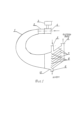
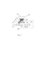
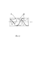
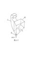
Предложенное устройство представлено на фиг.1 - общий вид в поперечном сечении, фиг.2 - устройство подачи коагулянта, фиг.3 - статический смеситель с набором винтовых турбулизаторов, фиг.4 - корпус с камерой стабилизации.The proposed device is shown in figure 1 - a general view in cross section, figure 2 - coagulant supply device, figure 3 - static mixer with a set of helical turbulators, figure 4 - housing with a stabilization chamber.
Здесь:Here:
1 - корпус, 2 - камера смешения, 3 - устройство подачи коагулянта, 4 - патрубок подачи загрязненной воды, 5 - патрубок подачи промывной жидкости, 6 - патрубок отвода чистой воды, 7 - тонкослойные пластины, 8 - промывные желоба, 9 - патрубок отвода шлама, 10 - камера стабилизации, 11 -воронка, 12 - ленточный конвейер, 13 - бункер, 14 - коагулянт, 15 - заслонка, 16 - весы рычажные, 17 - противовес, 18 - датчик, 19 - винтовые элементы смесителя.1 - housing, 2 - mixing chamber, 3 - coagulant supply device, 4 - contaminated water supply pipe, 5 - washing liquid supply pipe, 6 - clean water outlet pipe, 7 - thin-layer plates, 8 - washing troughs, 9 - outlet pipe sludge, 10 - stabilization chamber, 11 - funnel, 12 - belt conveyor, 13 - hopper, 14 - coagulant, 15 - damper, 16 - lever scales, 17 - counterweight, 18 - sensor, 19 - screw elements of the mixer.
Устройство центробежной очистки представляет собой корпус 1 в виде спирального диффузорного канала с горизонтальной осью. В верхней узкой части корпуса 1, к нему крепится камера смешения 2, в котором расположены винтовые элементы 19. К камере смешения 2 крепится патрубок подачи загрязненной воды 4; над которой расположено устройство подачи коагулянта 3. Устройство подачи коагулянта 3 состоит из бункера 13, содержащего порошковый коагулянт 14. Бункер 13 имеет заслонку 15, которая может регулировать размер проходного отверстия бункера. Под проходным отверстием бункера 13 установлен ленточный конвейер 12, который приводится в движение от постороннего источника (не показан).The centrifugal cleaning device is a
Ленточный конвейер 12 закреплен на одном из плеч рычажных весов 16. Другое плечо рычажных весов 16 имеет противовес 17, имеющий возможность перемещения вдоль плеча, имеющего градуировочную разметку. Положение рычажных весов 16 контролируется датчиком 18, расположенного под плечом рычажных весов 16 с ленточным конвейером 12.The
На патрубке подачи загрязненной воды 4 под ленточным конвейером 12, в зоне высыпания коагулянта расположена воронка 11.A
В нижней расширенной части корпуса 1 расположена камера стабилизации 10, которая имеет несимметричную конфигурацию и нижняя стенка камеры имеет наклон к патрубку отвода шлама 9.In the lower expanded part of the
К камере стабилизации 10 примыкает зона тонкослойного отстаивания, состоящая из тонкослойных пластин 7, имеющих во входной части промывные желоба 8, в которые промывная вода подается через патрубок 5, а после желобов 8 сливается в общий патрубок отвода шлама 9.The
Предложенное устройство работает следующим образом. Перед началом процесса очистки проводят анализ сточных вод. Подлежащих очистке, вид, характер и концентрацию загрязняющих компонентов (соли железа, алюминия, магния, известь, и др.) и его необходимое количество.The proposed device works as follows. Before starting the treatment process, an analysis of wastewater is carried out. To be cleaned, the type, nature and concentration of polluting components (salts of iron, aluminum, magnesium, lime, etc.) and its required amount.
На основании полученных исходных данных настраивают устройство подачи коагулянта 3, путем регулирования рычажных весов 16. Для этого устанавливают противовес 17 таким образом на градуированном плече весов 16, чтобы обеспечивать на ленточном конвейере 12 необходимое количество коагулянта 14. С целью упрощения настройки весов 16 можно использовать предварительно установленную тарировочную характеристику Gк=f (Lпp), где Gк - необходимый вес коагулянта, Lпp - число делений на градуированной разметке весов 16.Based on the initial data obtained, the coagulant supply device 3 is adjusted by adjusting the lever scales 16. To do this, the
После настройки устройства 3, приступают к процессу очистки и начинают подавать сточную воду в патрубок 4 и включают привод (не показан) ленточного конвейера 12. По конвейеру 12 в сточную воду подается необходимое количество коагулянта 14 через воронку 11. Далее, вода с коагулянтом поступает к камеру смешения 2, где проходя через винтовые соединения 19, активно турбулизируется и тщательно перемешивается. За счет действия коагулянта частицы загрязнителя укрупняются в хлопья и попадают в зону действия центробежных сил в спиральном диффузорном канале корпуса 1 отбрасываются к стенке. Сгущенный пристеночный шлам поступает в камеру стабилизации 10, где за счет наклонного днища, сползает в патрубок 9 и удаляется из устройства. В камере стабилизации 10 скорость потока воды снижается за счет диффузорности. Из камеры стабилизации 10 вода, очищенная от значительной части загрязняющих веществ, поступает в зону тонкослойных пластин 7, где происходит доочитска от оставшихся загрязнителей. Осевшие на пластине 7 частицы сползают вниз в промывные желоба 8, откуда смываются промывной водой из патрубка 5 и отводятся в патрубок отвода шлама 9. Очищенная от загрязняющих веществ вода из патрубка 6 отводится потребителям.After setting up the device 3, they start the cleaning process and start supplying wastewater to the pipe 4 and turn on the drive (not shown) of the
Таким образом, используя предложенное устройство центробежной очистки можно значительно повысить качество очистки сточных вод.Thus, using the proposed centrifugal treatment device, it is possible to significantly improve the quality of wastewater treatment.
Claims (3)
Publications (2)
| Publication Number | Publication Date |
|---|---|
| RU2022119998A RU2022119998A (en) | 2022-08-12 |
| RU2796110C2 true RU2796110C2 (en) | 2023-05-17 |
Family
ID=
Citations (5)
| Publication number | Priority date | Publication date | Assignee | Title |
|---|---|---|---|---|
| SU1017679A1 (en) * | 1982-01-14 | 1983-05-15 | Литовское Научно-Производственное Объединение По Комплексному Проектированию Станкостроительных Предприятий | Apparatus for purifying effluents |
| SU1657214A1 (en) * | 1989-03-20 | 1991-06-23 | Государственный Проектный Институт "Южгипрошахт" | Unit for treatment of natural water and sewage |
| US7527726B2 (en) * | 2006-01-25 | 2009-05-05 | Q'max Solutions Inc. | Fluid treatment apparatus |
| RU184254U1 (en) * | 2018-06-04 | 2018-10-19 | Федеральное Государственное Бюджетное Образовательное Учреждение Высшего Образования "Казанский Национальный Исследовательский Технический Университет Им. А.Н. Туполева-Каи", (Книту-Каи) | Flotation hydrocyclone |
| RU193149U1 (en) * | 2019-04-01 | 2019-10-15 | Федеральное государственное бюджетное образовательное учреждение высшего образования "Казанский национальный исследовательский технический университет им. А.Н. Туполева-КАИ" (КНИТУ-КАИ) | Centrifugal cleaning device |
Patent Citations (5)
| Publication number | Priority date | Publication date | Assignee | Title |
|---|---|---|---|---|
| SU1017679A1 (en) * | 1982-01-14 | 1983-05-15 | Литовское Научно-Производственное Объединение По Комплексному Проектированию Станкостроительных Предприятий | Apparatus for purifying effluents |
| SU1657214A1 (en) * | 1989-03-20 | 1991-06-23 | Государственный Проектный Институт "Южгипрошахт" | Unit for treatment of natural water and sewage |
| US7527726B2 (en) * | 2006-01-25 | 2009-05-05 | Q'max Solutions Inc. | Fluid treatment apparatus |
| RU184254U1 (en) * | 2018-06-04 | 2018-10-19 | Федеральное Государственное Бюджетное Образовательное Учреждение Высшего Образования "Казанский Национальный Исследовательский Технический Университет Им. А.Н. Туполева-Каи", (Книту-Каи) | Flotation hydrocyclone |
| RU193149U1 (en) * | 2019-04-01 | 2019-10-15 | Федеральное государственное бюджетное образовательное учреждение высшего образования "Казанский национальный исследовательский технический университет им. А.Н. Туполева-КАИ" (КНИТУ-КАИ) | Centrifugal cleaning device |
Non-Patent Citations (1)
| Title |
|---|
| Д.А. КРИВОШЕИН, П.П. КУКИН, В.Л. ЛАПИН И ДР. ИНЖЕНЕРНАЯ ЗАЩИТА ПОВЕРХНОСТНЫХ ВОД ОТ ПРОМЫШЛЕННЫХ СТОКОВ. УЧЕБНОЕ ПОСОБИЕ ДЛЯ СТУДЕНТОВ ВЫСШИХ УЧЕБНЫХ ЗАВЕДЕНИЙ. - 2-Е ИЗД., СТЕР. - М. ВЫСШАЯ ШКОЛА. 2008. - 343 с.. * |
Similar Documents
| Publication | Publication Date | Title |
|---|---|---|
| CN103118755B (en) | Water treatment method and system | |
| RU2009125640A (en) | METHOD AND INSTALLATION FOR WATER TREATMENT | |
| CN102105401A (en) | Primary equalization settling tank | |
| CA1105845A (en) | Method and apparatus for separating solids from liquids | |
| CA1138135A (en) | Liquid treatment apparatus | |
| US8168073B2 (en) | Waste concrete and aggregate reclaimer | |
| RU2796110C2 (en) | Centrifugal cleaning device | |
| CN207619149U (en) | A kind of granulation clarification desulfurization wastewater treatment system | |
| US5809825A (en) | Sampling device for aerated liquids | |
| CN101772368B (en) | Concentration equipment and methods | |
| CN113003964B (en) | Continuous washing dechlorination device for waste incineration fly ash | |
| CN110538514A (en) | Resource recovery detecting system based on sewage and slurry separation treatment | |
| CN101652165A (en) | Grit chamber and method for controlling it | |
| US5589064A (en) | Apparatus for liquid solid separation of liquid effluents or wastewater | |
| RU193149U1 (en) | Centrifugal cleaning device | |
| CN210457612U (en) | Wastewater pretreatment equipment | |
| RU2471719C1 (en) | Method of adjusting water treatment processes in contact clarifiers and device to this end | |
| KR20030044443A (en) | Venturi type precipitation device | |
| RU143766U1 (en) | MIXER | |
| DK160147B (en) | Process and appliance for purifying liquid media, in particular sewage | |
| SU1722583A1 (en) | Device for thickening and classification of pulp | |
| RU2104079C1 (en) | Thin-layer settler | |
| SU1230624A1 (en) | Apparatus for clarifying suspensions | |
| RU2016113901A (en) | METHOD AND INSTALLATION FOR CLEANING A LIQUID PRODUCT | |
| CN213375259U (en) | High-efficient desulfurization waste water precipitation equipment |