RU2837103C1 - Power plant and method of its operation - Google Patents
Power plant and method of its operation Download PDFInfo
- Publication number
- RU2837103C1 RU2837103C1 RU2024119381A RU2024119381A RU2837103C1 RU 2837103 C1 RU2837103 C1 RU 2837103C1 RU 2024119381 A RU2024119381 A RU 2024119381A RU 2024119381 A RU2024119381 A RU 2024119381A RU 2837103 C1 RU2837103 C1 RU 2837103C1
- Authority
- RU
- Russia
- Prior art keywords
- heat exchanger
- water
- carbon dioxide
- pressure contact
- heating
- Prior art date
Links
Images
Abstract
Description
Изобретение относится к области теплоэнергетики, в частности к теплофикационным парогазовым установкам и предназначено для централизованного теплоснабжения с генерацией электрической энергии на собственные нужды и отпуском в жидкой фазе кислорода и диоксида углерода внешним потребителям.The invention relates to the field of thermal power engineering, in particular to combined-cycle heating plants, and is intended for centralized heat supply with the generation of electrical energy for in-house needs and the release of oxygen and carbon dioxide in the liquid phase to external consumers.
Известен способ работы теплосиловой паровой установки (патент РФ №2812135, опубл. 23.01.2024), в котором топливо сжигается в потоке воздуха в камере сгорания. Горячий газ из камеры сгорания в котле греет рабочее тело парового цикла Ренкина. Рабочее тело парового цикла - углекислый газ. Конденсация углекислого газа за паровой турбиной осуществляется в конденсаторе охлаждением водой, которая после конденсатора поступает в воздушный теплообменник-испаритель где охлаждается льдом и с помощью теплового парокомпрессионного насоса, передавая тепло потребителю тепла. Выхлопные газы после котла дополнительно охлаждаются водой из воздушного теплообменника-испарителя, после чего выбрасываются в атмосферу. К недостаткам данного способа следует отнести низкий уровень температур теплоносителя, передаваемый потребителям тепла (65-70 и 85-90°С), да и этот уровень температур достигается неэффективной работой теплового насоса, т.к. слишком больший подъем температур от ~0 до 65-70 или 85-90°С (низкий коэффициент преобразования). Установка также выбрасывает в атмосферу парниковый газ СО2 - результат химической реакции углеводородного топлива и кислорода воздуха в камере сгорания котла.A method of operating a thermal power steam plant is known (RU Patent No. 2812135, published on 23.01.2024), in which fuel is burned in an air flow in a combustion chamber. Hot gas from the combustion chamber in the boiler heats the working fluid of the Rankine steam cycle. The working fluid of the steam cycle is carbon dioxide. Condensation of carbon dioxide behind the steam turbine is carried out in the condenser by cooling with water, which after the condenser enters the air heat exchanger-evaporator, where it is cooled with ice and with the help of a thermal vapor compression pump, transferring heat to the heat consumer. The exhaust gases after the boiler are additionally cooled with water from the air heat exchanger-evaporator, after which they are released into the atmosphere. The disadvantages of this method include the low temperature level of the coolant transferred to heat consumers (65-70 and 85-90 ° C), and this temperature level is achieved by inefficient operation of the heat pump, because too much temperature rise from ~0 to 65-70 or 85-90°C (low conversion factor). The unit also emits greenhouse gas CO2 into the atmosphere - the result of a chemical reaction between hydrocarbon fuel and oxygen in the combustion chamber of the boiler.
Известна установка для выработки тепловой и механической энергии и способ ее работы, выбранная в качестве наиболее близкого аналога (патент РФ №2805401, опубл. 16.10.2023), состоящая из линий подачи сжиженных кислорода, природного газа и воды в камеру сгорания, соединенную с по меньшей мере одной парогазовой турбиной, выход которой соединен с линией охлаждения и конденсации отработанных газов, включающей рекуперативный охладитель отработанных газов, выполненный с возможностью подогрева воды, поступающей в камеру сгорания, контактный теплообменник низкого давления, компрессор, контактный теплообменник высокого давления и устройство ожижения диоксида углерода. В камеру сгорания подают сжиженные СПГ и кислород, а также воду из контактного теплообменника низкого давления. Газы из камеры сгорания подают на парогазовую турбину, после которой отработанные газы поступают в линию охлаждения и конденсации отработанных газов (ОГ), где их ступенчатого охлаждают в рекуперативном охладителе, в контактных теплообменниках низкого и высокого давления до температур конденсации воды и далее в устройстве ожижения диоксида углерода до температуры конденсации диоксида углерода. Сконденсированную воду из контактного теплообменника низкого давления направляют к по меньшей мере одной секции подачи воды этого же контактного теплообменника через подогреватель сетевой воды.A known installation for generating thermal and mechanical energy and a method for its operation, selected as the closest analogue (RU Patent No. 2805401, published on 16.10.2023), consists of lines for feeding liquefied oxygen, natural gas and water into a combustion chamber connected to at least one combined cycle turbine, the outlet of which is connected to a line for cooling and condensing exhaust gases, including a recuperative exhaust gas cooler designed to heat the water entering the combustion chamber, a low-pressure contact heat exchanger, a compressor, a high-pressure contact heat exchanger and a carbon dioxide liquefaction device. Liquefied LNG and oxygen, as well as water from the low-pressure contact heat exchanger, are fed into the combustion chamber. The gases from the combustion chamber are fed to the steam-gas turbine, after which the exhaust gases enter the exhaust gas (EG) cooling and condensation line, where they are cooled in stages in the recuperative cooler, in the low- and high-pressure contact heat exchangers to water condensation temperatures and then in the carbon dioxide liquefaction device to the carbon dioxide condensation temperature. The condensed water from the low-pressure contact heat exchanger is sent to at least one water supply section of the same contact heat exchanger through the network water heater.
К недостаткам наиболее близкого аналога можно отнести снижение надежности установки за счет быстрого перехода на номинальный режим работы с высокой температурой сгорания.The disadvantages of the closest analogue include a decrease in the reliability of the installation due to a rapid transition to the nominal operating mode with a high combustion temperature.
Задачей, на решение которой направлено изобретение, является устранение указанных недостатков наиболее близкого аналога.The task that the invention is aimed at solving is to eliminate the indicated disadvantages of the closest analogue.
Технический результат заключается в повышении надежности установки за счет повышения равномерности прогрева систем установки перед выводом ее на номинальный режим работы.The technical result consists in increasing the reliability of the installation by increasing the uniformity of heating of the installation systems before bringing it to the nominal operating mode.
Технический результат достигается энергетической установкой, состоящей из линий подачи сжиженных кислорода, природного газа и диоксида углерода, а также воды в камеру сгорания, соединенную с по меньшей мере одной парогазовой турбиной, выход которой соединен с линией охлаждения и конденсации отработанных газов, включающей рекуперативный охладитель отработанных газов, выполненный с возможностью подогрева воды, подающейся насосом воды в камеру сгорания из контактного теплообменника низкого давления по линии подачи воды, контактный теплообменник низкого давления, компрессор, контактный теплообменник высокого давления и устройство ожижения диоксида углерода, один из выходов для сконденсированной воды контактного теплообменника низкого давления соединен с контуром низкого давления, выполненным с возможностью подачи воды циркуляционным насосом воды через теплообменники подогрева природного газа и кислорода к по меньшей мере одной секции подачи охлаждающей воды контактного теплообменника низкого давления, при этом линия подачи сжиженного диоксида углерода в камеру сгорания включает блок хранения диоксида углерода, соединенный с устройством ожижения диоксида углерода, насос диоксида углерода и теплообменник подогрева пускового диоксида углерода, линия подачи воды в камеру сгорания дополнительно включает клапан перепуска воды, установленный ниже по потоку рекуперативного охладителя отработанных газов и соединенный трассой перепуска с линией охлаждения и конденсации отработанных газов, которая включает клапан сброса выхлопных газов в атмосферу, при этом теплообменники подогрева природного газа и кислорода, установленные в линиях подачи сжиженных природного газа и кислорода, а также теплообменник подогрева пускового диоксида углерода включают нагревательные элементы.The technical result is achieved by a power plant consisting of lines for feeding liquefied oxygen, natural gas and carbon dioxide, as well as water into a combustion chamber connected to at least one combined cycle turbine, the outlet of which is connected to a line for cooling and condensing exhaust gases, including a recuperative cooler of exhaust gases, configured to heat water fed by a water pump into the combustion chamber from a low-pressure contact heat exchanger along a water feed line, a low-pressure contact heat exchanger, a compressor, a high-pressure contact heat exchanger and a carbon dioxide liquefaction device, one of the outlets for condensed water of the low-pressure contact heat exchanger is connected to a low-pressure circuit configured to feed water by a water circulation pump through heat exchangers for heating natural gas and oxygen to at least one section for feeding cooling water of the low-pressure contact heat exchanger, wherein the line for feeding liquefied carbon dioxide into the combustion chamber includes a carbon dioxide storage unit connected to the liquefaction device carbon dioxide, a carbon dioxide pump and a heat exchanger for heating the starting carbon dioxide, the line for feeding water to the combustion chamber additionally includes a water bypass valve installed downstream of the recuperative cooler of the exhaust gases and connected by a bypass route to the line for cooling and condensing the exhaust gases, which includes a valve for discharging exhaust gases into the atmosphere, wherein the heat exchangers for heating natural gas and oxygen installed in the lines for feeding liquefied natural gas and oxygen, as well as the heat exchanger for heating the starting carbon dioxide include heating elements.
Дополнительно линия охлаждения и конденсации отработанных газов включает теплообменный аппарат, расположенный перед контактным теплообменником низкого давления и встроенный в выпарной аппарат, выход для воды которого соединен с по меньшей мере одной секцией подачи воды в контактный теплообменник высокого давления через теплообменник охлаждающей воды контактного теплообменника высокого давления, при этом выход для воды контактного теплообменника высокого давления соединен со входом для охлаждающей воды выпарного аппарата через по меньшей мере один питательный насос и теплообменник охлаждающей воды контактного теплообменника высокого давления, выход для пара выпарного аппарата соединен с конденсатором, имеющим поверхностный теплообменник для подогрева сетевой воды, выход которого соединен со входом в теплосеть, а вход - с выходом подогревателя сетевой воды, один из входов которого соединен с выходом из теплосети, а другой его вход соединен с выходом воды контактного теплообменника низкого давления, а другой выход - с по меньшей мере одной секцией подачи воды контактного теплообменника низкого давления через циркуляционный насос воды контура низкого давления.Additionally, the exhaust gas cooling and condensation line includes a heat exchanger located in front of the low-pressure contact heat exchanger and built into the evaporator, the water outlet of which is connected to at least one section of the water supply to the high-pressure contact heat exchanger through the cooling water heat exchanger of the high-pressure contact heat exchanger, wherein the water outlet of the high-pressure contact heat exchanger is connected to the cooling water inlet of the evaporator through at least one feed pump and the cooling water heat exchanger of the high-pressure contact heat exchanger, the steam outlet of the evaporator is connected to a condenser having a surface heat exchanger for heating network water, the outlet of which is connected to the inlet to the heating network, and the inlet is connected to the outlet of the network water heater, one of the inlets of which is connected to the outlet of the heating network, and its other inlet is connected to the water outlet of the low-pressure contact heat exchanger, and the other outlet is connected to at least one section of the water supply to the low-pressure contact heat exchanger through the circulation pump of the low-pressure circuit water. pressure.
Клапан сброса выхлопных газов в атмосферу установлен после контактного теплообменника низкого давления и перед контактным теплообменником высокого давления.The exhaust gas discharge valve into the atmosphere is installed after the low-pressure contact heat exchanger and before the high-pressure contact heat exchanger.
Теплообменники подогрева природного газа, кислорода и диоксида углерода выполнены с возможностью их нагрева нагревательными элементами через промежуточный теплоноситель.Heat exchangers for heating natural gas, oxygen and carbon dioxide are designed with the possibility of heating them with heating elements through an intermediate heat carrier.
Контактный теплообменник высокого давления дополнительно содержит поверхностный теплообменник охлаждения сконденсированной воды, соединенный с холодильной установкой, при этом указанная сконденсированная вода служит для охлаждения отработанных газов и циркулирует через контактный теплообменник высокого давления и выпарной аппарат, и является раствором по меньшей мере одной гигроскопической соли одной из групп нитрата кальция, нитрата аммония, сульфата аммония, нитрата бария, перхлората бария, формиата калия, хлората натрия, нитрата натрия, нитрата калия, хлорида натрия, хлорида кальция, хлорида лития или их комбинации, а конденсатор включает по меньшей мере два выхода для сконденсированной воды, по меньшей мере один из которых соединен со входом в теплосеть через насос, а по меньшей мере один другой выход для сконденсированной воды служит для вывода избытков воды из установки.The high-pressure contact heat exchanger additionally comprises a surface heat exchanger for cooling condensed water, connected to the refrigeration unit, wherein said condensed water serves to cool the exhaust gases and circulates through the high-pressure contact heat exchanger and the evaporator, and is a solution of at least one hygroscopic salt of one of the groups of calcium nitrate, ammonium nitrate, ammonium sulfate, barium nitrate, barium perchlorate, potassium formate, sodium chlorate, sodium nitrate, potassium nitrate, sodium chloride, calcium chloride, lithium chloride or a combination thereof, and the condenser includes at least two outlets for condensed water, at least one of which is connected to the inlet to the heating network via a pump, and at least one other outlet for condensed water serves to remove excess water from the unit.
Линия подачи сжиженного кислорода содержит установку криогенного разделения воздуха, по меньшей мере один компрессор которой приводится энергией, вырабатываемой с помощью по меньшей мере одной парогазовой турбины, при этом установка криогенного разделения воздуха дополнительно соединена с блоком накопления и хранения кислорода, при этом энергетическая установка выполнена с возможностью обеспечения передачи избытка воды из конденсатора и контактного теплообменника низкого давления, диоксида углерода и кислорода от блоков накопления и хранения диоксида углерода и кислорода, а также газов, полученных при сжижении кислорода в установке криогенного разделения воздуха, к внешнему потребителю.The liquefied oxygen supply line comprises a cryogenic air separation unit, at least one compressor of which is driven by energy generated by at least one steam-gas turbine, wherein the cryogenic air separation unit is additionally connected to an oxygen accumulation and storage unit, wherein the power plant is designed with the possibility of ensuring the transfer of excess water from the condenser and low-pressure contact heat exchanger, carbon dioxide and oxygen from the carbon dioxide and oxygen accumulation and storage units, as well as gases obtained during the liquefaction of oxygen in the cryogenic air separation unit, to an external consumer.
Технический результат также достигается способом работы энергетической установки по любому из предыдущих пунктов, заключающийся в том, что при пуске включают циркуляционный насос контура низкого давления воды, нагревательные элементы для подогрева теплообменников подогрева природного газа, кислорода и диоксида углерода; открывают клапан сброса выхлопных газов в атмосферу; в линии подачи воды в камеру сгорания переключают клапан перепуска воды в положение перекрытия подачи воды в камеру сгорания и открытия направления воды в трассу перепуска и включают насос подачи воды из контактного теплообменника низкого давления; в камеру сгорания подают кислород в количестве, необходимом для розжига камеры сгорания, и подают диоксид углерода в количестве, необходимом для балластирования горячих газов при запуске; в камеру сгорания подают природный газ в количестве, необходимом для розжига камеры сгорания, с последующим увеличением расхода для прогрева систем; разжигают камеру сгорания.The technical result is also achieved by the method of operating the power plant according to any of the previous points, which consists in that, upon start-up, the circulation pump of the low-pressure water circuit, heating elements for heating the heat exchangers for heating the natural gas, oxygen and carbon dioxide are switched on; the valve for discharging exhaust gases into the atmosphere is opened; in the line for supplying water to the combustion chamber, the water bypass valve is switched to the position of shutting off the water supply to the combustion chamber and opening the direction of water into the bypass line and the pump for supplying water from the low-pressure contact heat exchanger is switched on; oxygen is supplied to the combustion chamber in the amount necessary for igniting the combustion chamber, and carbon dioxide is supplied in the amount necessary for ballasting the hot gases upon start-up; natural gas is supplied to the combustion chamber in the amount necessary for igniting the combustion chamber, with a subsequent increase in flow rate for warming up the systems; the combustion chamber is ignited.
Количество кислорода, природного газа и диоксида углерода, подаваемые в камеру сгорания, увеличивают до достижения газами, полученными от сгорания, рабочей температуры в течение заданного времени, необходимого для прогрева и раскрутки парогазовой турбины, и прогрева контактного теплообменника низкого давления.The amount of oxygen, natural gas and carbon dioxide supplied to the combustion chamber is increased until the gases obtained from combustion reach the operating temperature within a specified time required to warm up and spin up the combined cycle turbine and warm up the low pressure contact heat exchanger.
Дополнительно включают питательные насосы для циркуляции воды через выпарной аппарат, теплообменник охлаждающей воды контактного теплообменника высокого давления и сам контактный теплообменник высокого давления.Additionally, feed pumps are included for circulating water through the evaporator, a heat exchanger for cooling water of the high-pressure contact heat exchanger, and the high-pressure contact heat exchanger itself.
По окончании заданного времени для прогрева отключают нагревательные элементы теплообменников подогрева природного газа, кислорода и диоксида углерода, закрывают клапан сброса выхлопных газов в атмосферу, запускают компрессор, переключают клапан перепуска воды в положение перекрытия направления воды в трассу перепуска и открытия направления воды в камеру сгорания и прекращают подачу диоксида углерода.At the end of the specified warm-up time, the heating elements of the heat exchangers for heating natural gas, oxygen and carbon dioxide are switched off, the exhaust gas discharge valve into the atmosphere is closed, the compressor is started, the water bypass valve is switched to the position of blocking the direction of water into the bypass line and opening the direction of water into the combustion chamber and the supply of carbon dioxide is stopped.
Далее включают холодильную установку и включают циркуляцию теплоносителя через поверхностный теплообменник контактного теплообменника высокого давления и холодильную установку, а также включают циркуляцию воды из тепловой сети через подогреватель сетевой воды и поверхностный теплообменник для подогрева сетевой воды обратно в тепловую сеть.Next, the refrigeration unit is switched on and the circulation of the coolant is switched on through the surface heat exchanger of the high-pressure contact heat exchanger and the refrigeration unit, and the circulation of water from the heating network is switched on through the network water heater and the surface heat exchanger for heating the network water back into the heating network.
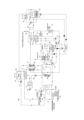
На представленной фигуре показана принципиальная схема энергетической установки.The figure shown is a schematic diagram of a power plant.
На фигуре представлены следующие обозначения:The following symbols are shown on the figure:
1 - насос кислородный (O2);1 - oxygen pump (O 2 );
2 - насос сжиженного природного газа (СПГ);2 - liquefied natural gas (LNG) pump;
3 - насос диоксида углерода (CO2);3 - carbon dioxide (CO 2 ) pump;
4 - насос воды (Н2O);4 - water pump ( H2O );
5 - теплообменник-утилизатор холода СПГ;5 - heat exchanger-recovery unit for LNG cold;
6 - теплообменник для подогрева СПГ;6 - heat exchanger for heating LNG;
7 - камера сгорания;7 - combustion chamber;
8 - теплообменник-утилизатор холода кислорода;8 - heat exchanger-oxygen cold utilizer;
9 - теплообменник для подогрева кислорода;9 - heat exchanger for heating oxygen;
10 - установка холодильная воды контура высокого давления;10 - installation of cooling water of high pressure circuit;
11 - блок накопления и хранения диоксида углерода;11 - carbon dioxide accumulation and storage unit;
12 - турбина парогазовая;12 - steam-gas turbine;
13 - охладитель отработанных газов рекуперативный линии подачи воды в камеру сгорания (7);13 - exhaust gas cooler, recuperative water supply line to the combustion chamber (7);
14 - компрессор установки криогенного разделения воздуха;14 - compressor of the cryogenic air separation unit;
15 - теплообменник контактный низкого давления;15 - low pressure contact heat exchanger;
16 - первая секция подачи воды контактного теплообменника (15);16 - first section of water supply of contact heat exchanger (15);
17 - вторая секция подачи воды контактного теплообменника (15);17 - the second section of the water supply of the contact heat exchanger (15);
18 - компрессор;18 - compressor;
19 - теплообменник контактный высокого давления;19 - high pressure contact heat exchanger;
20 - устройство ожижения CO2;20 - CO2 liquefaction device;
21 - установка разделения воздуха криогенная (ВРУ);21 - cryogenic air separation unit (ASU);
22 - установка холодильная;22 - refrigeration unit;
23 - насос циркуляционной воды контура низкого давления;23 - low pressure circuit circulating water pump;
24 - насос циркуляционный;24 - circulation pump;
25 - подогреватель сетевой воды;25 - network water heater;
26 - встроенный поверхностный теплообменник охлаждения сконденсированной воды контактного теплообменника (19) высокого давления;26 - built-in surface heat exchanger for cooling condensed water of the high-pressure contact heat exchanger (19);
27 - питательный насос охлаждающей воды контактного теплообменника (19) высокого давления;27 - feed pump for cooling water of the high-pressure contact heat exchanger (19);
28 - теплообменник охлаждающей воды контактного теплообменника (19) высокого давления28 - high pressure contact heat exchanger cooling water heat exchanger (19)
29 - выпарной аппарат;29 - evaporator;
30 - встроенный поверхностный теплообменный аппарат горячих газов;30 - built-in surface heat exchanger for hot gases;
31 - конденсатор;31 - capacitor;
32 - встроенный поверхностный теплообменник сетевой воды;32 - built-in surface heat exchanger for network water;
33 - блок накопления и хранения кислорода;33 - oxygen accumulation and storage unit;
34 - установка ожижения природного газа;34 - natural gas liquefaction plant;
35 - насос подачи кислорода к внешнему потребителю;35 - oxygen supply pump to external consumer;
36 - насос диоксида углерода;36 - carbon dioxide pump;
37 - теплообменник для подогрева пускового диоксида углерода;37 - heat exchanger for heating starting carbon dioxide;
38 - нагревательный элемент;38 - heating element;
39 - клапан сброса выхлопных газов;39 - exhaust gas discharge valve;
40 - задвижка природного газа от источника природного газа (магистрали, баллона, цистерны или т.п.);40 - natural gas valve from a natural gas source (main line, cylinder, tank, etc.);
41 - насос тепловой сети;41 - heating network pump;
42 - клапан перепуска воды в линии подачи воды в камеру (7) сгорания;42 - water bypass valve in the water supply line to the combustion chamber (7);
43 - трасса перепуска воды.43 - water bypass route.
Стрелками показаны направления движения сред в установке.The arrows show the directions of movement of the media in the installation.
Энергетическая установка состоит из камеры (7) сгорания, соединенной с источником (21) кислорода линией подачи кислорода, включающей теплообменник установки (34) ожижения природного газа, кислородный насос (1), теплообменник-утилизатор (8) холода кислорода, расположенный в устройстве (20) ожижения диоксида углерода, теплообменник (9) для подогрева кислорода. При этом, источником кислорода может являться установка (21) криогенного разделения воздуха, соединенная с блоком (33) накопления и хранения кислорода. Камера (7) сгорания также соединена с источником природного газа линией подачи природного газа, включающей задвижку (40) природного газа от источника природного газа, установку (34) ожижения природного газа, насос (2) сжиженного природного газа, теплообменник-утилизатор (5) холода СПГ и теплообменник (6) подогрева СПГ. Кроме того, камера (7) сгорания соединена с выходом для сконденсированной воды контактного теплообменника (15) низкого давления линией подачи воды, включающей насос (4) воды, рекуперативный охладитель (13) отработанных газов.The power plant consists of a combustion chamber (7) connected to an oxygen source (21) by an oxygen supply line including a heat exchanger of a natural gas liquefaction unit (34), an oxygen pump (1), a heat exchanger-utilizer (8) of oxygen cold located in a device (20) for liquefying carbon dioxide, a heat exchanger (9) for heating oxygen. In this case, the oxygen source can be a cryogenic air separation unit (21) connected to an oxygen accumulation and storage unit (33). The combustion chamber (7) is also connected to a natural gas source by a natural gas supply line including a valve (40) of natural gas from a natural gas source, a natural gas liquefaction unit (34), a liquefied natural gas pump (2), a heat exchanger-utilizer (5) of LNG cold and a heat exchanger (6) for heating LNG. In addition, the combustion chamber (7) is connected to the outlet for condensed water of the low-pressure contact heat exchanger (15) by a water supply line, including a water pump (4), a recuperative cooler (13) for exhaust gases.
Один из выходов для сконденсированной воды контактного теплообменника (15) низкого давления соединен с контуром низкого давления, выполненным с возможностью подачи воды циркуляционным насосом (23) воды через теплообменники (6, 9) подогрева природного газа и кислорода к по меньшей мере одной секции (17) подачи охлаждающей воды контактного теплообменника (15) низкого давления.One of the outlets for condensed water of the low-pressure contact heat exchanger (15) is connected to a low-pressure circuit designed to supply water by a water circulation pump (23) through heat exchangers (6, 9) for heating natural gas and oxygen to at least one section (17) for supplying cooling water of the low-pressure contact heat exchanger (15).
Линия подачи сжиженного диоксида углерода в камеру (7) сгорания включает блок (11) хранения диоксида углерода, соединенный с устройством (20) ожижения диоксида углерода, насос (36) диоксида углерода и теплообменник (37) подогрева пускового диоксида углерода, что повышает надежность установки за счет использования в качестве балластного газа при пуске и прогреве установки диоксида углерода.The line for feeding liquefied carbon dioxide into the combustion chamber (7) includes a carbon dioxide storage unit (11) connected to a carbon dioxide liquefaction device (20), a carbon dioxide pump (36) and a heat exchanger (37) for heating the starting carbon dioxide, which increases the reliability of the installation by using carbon dioxide as a ballast gas during the start-up and warm-up of the installation.
Линия подачи воды в камеру (7) сгорания дополнительно включает клапан (42) перепуска воды, установленный ниже по потоку рекуперативного охладителя (13) отработанных газов и соединенный трассой (43) перепуска с линией охлаждения и конденсации отработанных газов, что повышает надежность установки за счет перепуска холодной воды в линию охлаждения и конденсации отработанных газов по меньшей мере часть которой возвращается в контактный теплообменник (15) низкого давления, нагреваясь от горячих газов в линии охлаждения и конденсации.The water supply line to the combustion chamber (7) additionally includes a water bypass valve (42), installed downstream of the recuperative cooler (13) of the exhaust gases and connected by a bypass line (43) to the exhaust gas cooling and condensation line, which increases the reliability of the installation by bypassing cold water into the exhaust gas cooling and condensation line, at least part of which returns to the low-pressure contact heat exchanger (15), heating up from the hot gases in the cooling and condensation line.
Также линия охлаждения и конденсации отработанных газов включает клапан (39) сброса выхлопных газов в атмосферу, что повышает надежность установки за счет выпуска отработанных газов, содержащих большое количество воды в атмосферу. При этом клапан (39) сброса выхлопных газов в атмосферу установлен после контактного теплообменника (15) низкого давления и перед контактным теплообменником (19), что дополнительно повышает надежность установки за счет выпуска отработанных газов, содержащих большое количество воды в атмосферу, исключая таким образом выход компрессора (18) из строя.Also, the exhaust gas cooling and condensation line includes a valve (39) for discharging exhaust gases into the atmosphere, which increases the reliability of the unit by discharging exhaust gases containing a large amount of water into the atmosphere. In this case, the valve (39) for discharging exhaust gases into the atmosphere is installed after the low-pressure contact heat exchanger (15) and before the contact heat exchanger (19), which additionally increases the reliability of the unit by discharging exhaust gases containing a large amount of water into the atmosphere, thus eliminating the failure of the compressor (18).
Каждый теплообменник (6, 9) подогрева природного газа и кислорода, установленные в линиях подачи сжиженных природного газа и кислорода, а также теплообменник (37) подогрева пускового диоксида углерода включает нагревательный элемент (38) для их подогрева во время пуска и прогрева, что повышает надежность установки за счет повышения температуры сжиженных газов, подаваемых в камеру (7) сгорания. При этом подогрев теплообменников (6, 9 и 37) осуществляется нагревательным элементом (38) через промежуточный теплоноситель, в качестве которого может использоваться любой жидкий теплоноситель, например, вода, что дополнительно повышает надежность установки за счет исключения прямого контакта нагревательного элемента (38) с теплообменниками (6, 9 и 37).Each heat exchanger (6, 9) for heating natural gas and oxygen installed in the supply lines of liquefied natural gas and oxygen, as well as the heat exchanger (37) for heating the starting carbon dioxide, includes a heating element (38) for heating them during startup and warming up, which increases the reliability of the installation due to an increase in the temperature of the liquefied gases supplied to the combustion chamber (7). In this case, the heating of the heat exchangers (6, 9 and 37) is carried out by the heating element (38) through an intermediate heat carrier, which can be any liquid heat carrier, for example, water, which additionally increases the reliability of the installation due to the exclusion of direct contact of the heating element (38) with the heat exchangers (6, 9 and 37).
Выход камеры (7) сгорания соединен с по меньшей мере одной парогазовой турбиной (12), выработанная механическая энергия которой может передаваться по меньшей мере одному компрессору (14) установки (21) криогенного разделения воздуха и/или генератору электрической энергии для обеспечения электрической энергией по меньшей мере собственных нужд заявленной энергетической установки. Кроме того, камера (7) сгорания может быть соединена с по меньшей мере одной другой парогазовой турбиной соединенной с генератором электрической энергии для обеспечения электрической энергией по меньшей мере собственных нужд заявленной энергетической установки.The outlet of the combustion chamber (7) is connected to at least one combined-cycle turbine (12), the mechanical energy generated by which can be transferred to at least one compressor (14) of the cryogenic air separation unit (21) and/or an electric power generator to provide electric power for at least the auxiliary needs of the claimed power plant. In addition, the combustion chamber (7) can be connected to at least one other combined-cycle turbine connected to the electric power generator to provide electric power for at least the auxiliary needs of the claimed power plant.
Выход по меньшей мере одной парогазовой турбины (12) соединен с линией охлаждения и конденсации отработанных газов, включающей рекуперативный охладитель (13) отработанных газов, выполненный с возможностью подогрева воды, поступающей в камеру (7) сгорания из контактного теплообменника (15) низкого давления, контактный теплообменник (15) низкого давления, включающий по меньшей мере две секции (16, 17) подачи охлаждающей воды, компрессор (18), контактный теплообменник (19) высокого давления и устройство (20) ожижения диоксида углерода, выход диоксида углерода которого соединен с блоком (11) накопления и хранения диоксида углерода. При этом контактный теплообменник (19) высокого давления включает по меньшей мере одну секцию подачи охлаждающей воды, а также дополнительно включает поверхностный теплообменник (26), соединенный с холодильной установкой (10) через циркуляционный насос (24). Кроме того, устройство (20) ожижения диоксида углерода дополнительно включает теплообменник холодильной установки (22).The outlet of at least one combined-cycle turbine (12) is connected to an exhaust gas cooling and condensation line comprising a recuperative exhaust gas cooler (13) configured to heat water supplied to the combustion chamber (7) from a low-pressure contact heat exchanger (15), a low-pressure contact heat exchanger (15) comprising at least two cooling water supply sections (16, 17), a compressor (18), a high-pressure contact heat exchanger (19), and a carbon dioxide liquefaction device (20), the carbon dioxide outlet of which is connected to a carbon dioxide accumulation and storage unit (11). In this case, the high-pressure contact heat exchanger (19) comprises at least one cooling water supply section, and also additionally comprises a surface heat exchanger (26) connected to the refrigeration unit (10) via a circulation pump (24). In addition, the carbon dioxide liquefaction device (20) additionally includes a refrigeration unit heat exchanger (22).
Линия охлаждения и конденсации отработанных газов дополнительно включает теплообменный аппарат (30), расположенный перед контактным теплообменником (15) низкого давления и встроенный в выпарной аппарат (29).The exhaust gas cooling and condensation line additionally includes a heat exchanger (30) located in front of the low-pressure contact heat exchanger (15) and built into the evaporator (29).
Выход для воды выпарного аппарата (29) соединен с по меньшей мере одной секцией подачи воды в контактный теплообменник (19) высокого давления через питательный насос (27) и теплообменник (28) охлаждающей воды контактного теплообменника (19) высокого давления.The water outlet of the evaporator (29) is connected to at least one section of the water supply to the high-pressure contact heat exchanger (19) via a feed pump (27) and a heat exchanger (28) of the cooling water of the high-pressure contact heat exchanger (19).
Выход для воды контактного теплообменника (19) высокого давления соединен со входом для охлаждающей воды выпарного аппарата (29) через другой питательный насос (27) и теплообменник (28) охлаждающей воды контактного теплообменника (19) высокого давления.The water outlet of the high-pressure contact heat exchanger (19) is connected to the cooling water inlet of the evaporator (29) via another feed pump (27) and a cooling water heat exchanger (28) of the high-pressure contact heat exchanger (19).
Выход для пара выпарного аппарата (29) соединен с конденсатором (31), имеющим поверхностный теплообменник (32) для подогрева сетевой воды, выход которого (32) соединен со входом в теплосеть, а вход - с выходом подогревателя (25) сетевой воды.The steam outlet of the evaporator (29) is connected to a condenser (31) having a surface heat exchanger (32) for heating the network water, the outlet of which (32) is connected to the inlet of the heating network, and the inlet is connected to the outlet of the heater (25) of the network water.
Один из входов подогревателя (25) сетевой воды соединен с выходом из теплосети, а другой его вход соединен с выходом воды контактного теплообменника (15) низкого давления, а другой выход - с по меньшей мере одной секцией (16) подачи воды контактного теплообменника (15) низкого давления через циркуляционный насос (23) воды контура низкого давления.One of the inputs of the network water heater (25) is connected to the output from the heating network, and its other input is connected to the water output of the low-pressure contact heat exchanger (15), and the other output is connected to at least one section (16) for supplying water to the low-pressure contact heat exchanger (15) through the circulation pump (23) of the low-pressure circuit water.
Конденсатор (31) включает по меньшей мере два выхода для сконденсированной воды, по меньшей мере один из которых соединен со входом в теплосеть через насос, что дополнительно позволяет повысить эффективность установки за счет повышения использования тепла. По меньшей мере один другой выход для сконденсированной воды конденсатора (31) служит для вывода избытка воды из установки.The condenser (31) includes at least two outlets for condensed water, at least one of which is connected to the input to the heating network via a pump, which additionally allows for increasing the efficiency of the installation by increasing the use of heat. At least one other outlet for condensed water of the condenser (31) serves to remove excess water from the installation.
Вода для охлаждения отработанных газов, циркулирующая через контактный теплообменник (19) высокого давления, является раствором по меньшей мере одной гигроскопической соли, представляющей собой одну из групп нитрата кальция, нитрата аммония, сульфата аммония, нитрата бария, перхлората бария, формиата калия, хлората натрия, нитрата натрия, нитрата калия, хлорида натрия и хлорида кальция или их комбинации (см. RU 2809298), что дополнительно повышает надежность установки за счет повышения отбора тепла от отработанных газов и отбора влаги из отработанных газов.The water for cooling the exhaust gases, circulating through the high-pressure contact heat exchanger (19), is a solution of at least one hygroscopic salt, which is one of the groups of calcium nitrate, ammonium nitrate, ammonium sulfate, barium nitrate, barium perchlorate, potassium formate, sodium chlorate, sodium nitrate, potassium nitrate, sodium chloride and calcium chloride or a combination thereof (see RU 2809298), which additionally increases the reliability of the installation due to an increase in the heat removal from the exhaust gases and the removal of moisture from the exhaust gases.
Кроме того, энергетическая установка выполнена с возможностью обеспечения передачи избытка воды из конденсатора (31) и контактного теплообменника (15) низкого давления, диоксида углерода и кислорода от блоков (11 и 33) накопления и хранения диоксида углерода и кислорода, а также газов, таких как азот, первичный криптоноксеноновый концентрат, аргон и неоногелиевая смесь, полученных при сжижении кислорода в установке (21) криогенного разделения воздуха, к внешнему потребителю, что повышает эффективность установки за счет сбора и последующей реализации полученных в установке веществ.In addition, the power plant is designed with the possibility of ensuring the transfer of excess water from the condenser (31) and the low-pressure contact heat exchanger (15), carbon dioxide and oxygen from the carbon dioxide and oxygen accumulation and storage units (11 and 33), as well as gases such as nitrogen, primary krypton-xenon concentrate, argon and neon-helium mixture obtained during the liquefaction of oxygen in the cryogenic air separation plant (21), to an external consumer, which increases the efficiency of the plant by collecting and subsequently selling the substances obtained in the plant.
Энергетическая установка работает следующим образом.The power plant operates as follows.
При пуске включают циркуляционный насос (23) контура низкого давления воды, нагревательные элементы (38) для подогрева теплообменников (6, 9 и 37) подогрева природного газа, кислорода и диоксида углерода, что повышает надежность установки за счет повышения температуры сжиженных газов, подаваемых в камеру (7) сгорания.When starting, the circulation pump (23) of the low-pressure water circuit, heating elements (38) for heating the heat exchangers (6, 9 and 37) for heating natural gas, oxygen and carbon dioxide are switched on, which increases the reliability of the installation by increasing the temperature of the liquefied gases supplied to the combustion chamber (7).
Открывают клапан (39) сброса выхлопных газов в атмосферу, что повышает надежность установки за счет выпуска отработанных газов, содержащих большое количество воды в атмосферу.Open the valve (39) for discharging exhaust gases into the atmosphere, which increases the reliability of the installation by releasing exhaust gases containing a large amount of water into the atmosphere.
В линии подачи воды в камеру (7) сгорания переключают клапан (42) перепуска воды в положение перекрытия подачи воды в камеру (7) сгорания и открытия направления воды в трассу (43) перепуска и включают насос (4) подачи воды из контактного теплообменника (15) низкого давления, что повышает надежность установки за счет перепуска холодной воды в линию охлаждения и конденсации отработанных газов по меньшей мере часть которой возвращается в контактный теплообменник (15) низкого давления, нагреваясь от горячих газов в линии охлаждения и конденсации.In the line for supplying water to the combustion chamber (7), the water bypass valve (42) is switched to the position of shutting off the water supply to the combustion chamber (7) and opening the direction of water to the bypass line (43), and the pump (4) for supplying water from the low-pressure contact heat exchanger (15) is turned on, which increases the reliability of the installation by bypassing cold water into the exhaust gas cooling and condensation line, at least part of which returns to the low-pressure contact heat exchanger (15), heating up from the hot gases in the cooling and condensation line.
В камеру (7) сгорания подают кислород в количестве, необходимом для розжига камеры (7) сгорания, и подают диоксид углерода в количестве, необходимом для балластирования горячих газов при запуске, а также подают природный газ в количестве, необходимом для розжига камеры (7) сгорания и разжигают камеру (7) сгорания, например с помощью запального устройства (не показано).Oxygen is supplied to the combustion chamber (7) in the amount necessary for igniting the combustion chamber (7), and carbon dioxide is supplied in the amount necessary for ballasting the hot gases during start-up, and natural gas is supplied in the amount necessary for igniting the combustion chamber (7) and the combustion chamber (7) is ignited, for example, using an ignition device (not shown).
Далее количество кислорода, природного газа и диоксида углерода, подаваемые в камеру (7) сгорания, увеличивают до достижения газами, полученными от сгорания, рабочей температуры в течение заданного времени, необходимого для прогрева и раскрутки парогазовой турбины (12), и прогрева контактного теплообменника (15) низкого давления, что дополнительно повышает надежность установки за счет равномерного нагрева наиболее теплонагруженных элементов систем установки. При этом температура может быть определена датчиками температуры, установленными в по меньшей мере одном из таких элементов как: камера (7) сгорания, парогазовая турбина (12), контактный теплообменник (15) низкого давления, - а количество кислорода, природного газа и диоксида углерода, подаваемые в камеру (7) сгорания, изменяют соответствующими насосами (1, 2, 36), установленными в линиях подачи кислорода, природного газа и диоксида углерода в камеру (7) сгорания.Then the amount of oxygen, natural gas and carbon dioxide supplied to the combustion chamber (7) is increased until the gases obtained from combustion reach the operating temperature during a specified time required for warming up and spinning up the combined-cycle turbine (12) and warming up the low-pressure contact heat exchanger (15), which additionally increases the reliability of the plant due to uniform heating of the most heat-loaded elements of the plant systems. In this case, the temperature can be determined by temperature sensors installed in at least one of such elements as: combustion chamber (7), combined-cycle turbine (12), low-pressure contact heat exchanger (15), - and the amount of oxygen, natural gas and carbon dioxide supplied to the combustion chamber (7) is changed by the corresponding pumps (1, 2, 36) installed in the oxygen, natural gas and carbon dioxide supply lines to the combustion chamber (7).
Дополнительно включают питательные насосы (27) для циркуляции воды через выпарной аппарат (29), теплообменник (28) охлаждающей воды контактного теплообменника (19) высокого давления и сам контактный теплообменник (19) высокого давления, что дополнительно повышает надежность установки за счет равномерного нагрева наиболее теплонагруженных элементов систем установки.Additionally, feed pumps (27) are included for circulating water through the evaporator (29), a heat exchanger (28) for cooling water of the high-pressure contact heat exchanger (19) and the high-pressure contact heat exchanger (19) itself, which further increases the reliability of the installation due to uniform heating of the most heat-loaded elements of the installation systems.
По окончании заданного времени для прогрева, которое определяется, например по температуре, определенной упомянутыми датчиками температуры, или определенное в ходе расчета или эксперимента, отключают нагревательные элементы (38) теплообменников (6, 9 и 37) подогрева природного газа, кислорода и диоксида углерода, закрывают клапан (39) сброса выхлопных газов в атмосферу, запускают компрессор (18), переключают клапан (42) перепуска воды в положение перекрытия направления воды в трассу (43) перепуска и открытия направления воды в камеру (7) сгорания и прекращают подачу диоксида углерода.At the end of the specified time for warming up, which is determined, for example, by the temperature determined by the mentioned temperature sensors, or determined during the calculation or experiment, the heating elements (38) of the heat exchangers (6, 9 and 37) for heating natural gas, oxygen and carbon dioxide are switched off, the valve (39) for discharging exhaust gases into the atmosphere is closed, the compressor (18) is started, the water bypass valve (42) is switched to the position of blocking the direction of water into the bypass line (43) and opening the direction of water into the combustion chamber (7) and stopping the supply of carbon dioxide.
Включают холодильную установку (10) и включают циркуляцию теплоносителя через поверхностный теплообменник (26) контактного теплообменника (19) высокого давления и холодильную установку (10), а также включают циркуляцию воды из тепловой сети через подогреватель (25) сетевой воды и поверхностный теплообменник (32) для подогрева сетевой воды обратно в тепловую сеть.The refrigeration unit (10) is switched on and the circulation of the coolant is switched on through the surface heat exchanger (26) of the high-pressure contact heat exchanger (19) and the refrigeration unit (10), and the circulation of water from the heating network is switched on through the heater (25) of the network water and the surface heat exchanger (32) for heating the network water back into the heating network.
Далее осуществляют номинальный режим работы энергетической установки, например по графику тепловой сети.Next, the nominal operating mode of the power plant is carried out, for example, according to the heating network schedule.
Таким образом, достигается повышение надежности установки за счет повышения равномерности прогрева систем установки перед выводом ее на номинальный режим работы.In this way, the reliability of the installation is increased by increasing the uniformity of heating of the installation systems before bringing it to the nominal operating mode.
Claims (12)
Publications (1)
| Publication Number | Publication Date |
|---|---|
| RU2837103C1 true RU2837103C1 (en) | 2025-03-25 |
Family
ID=
Citations (3)
| Publication number | Priority date | Publication date | Assignee | Title |
|---|---|---|---|---|
| RU2698865C1 (en) * | 2018-10-29 | 2019-08-30 | Федеральное государственное бюджетное учреждение науки Объединенный институт высоких температур Российской академии наук (ОИВТ РАН) | Control method and apparatus for generating mechanical and thermal energy |
| RU2759793C1 (en) * | 2021-02-26 | 2021-11-17 | Федеральное государственное бюджетное учреждение науки Объединенный институт высоких температур Российской академии наук (ОИВТ РАН) | Installation for producing thermal and mechanical energy and method for its operation |
| RU2805401C1 (en) * | 2023-04-12 | 2023-10-16 | федеральное государственное бюджетное образовательное учреждение высшего образования "Национальный исследовательский университет "МЭИ" (ФГБОУ ВО "НИУ "МЭИ") | Installation for generating thermal and mechanical energy and method of its operation |
Patent Citations (3)
| Publication number | Priority date | Publication date | Assignee | Title |
|---|---|---|---|---|
| RU2698865C1 (en) * | 2018-10-29 | 2019-08-30 | Федеральное государственное бюджетное учреждение науки Объединенный институт высоких температур Российской академии наук (ОИВТ РАН) | Control method and apparatus for generating mechanical and thermal energy |
| RU2759793C1 (en) * | 2021-02-26 | 2021-11-17 | Федеральное государственное бюджетное учреждение науки Объединенный институт высоких температур Российской академии наук (ОИВТ РАН) | Installation for producing thermal and mechanical energy and method for its operation |
| RU2805401C1 (en) * | 2023-04-12 | 2023-10-16 | федеральное государственное бюджетное образовательное учреждение высшего образования "Национальный исследовательский университет "МЭИ" (ФГБОУ ВО "НИУ "МЭИ") | Installation for generating thermal and mechanical energy and method of its operation |
Similar Documents
| Publication | Publication Date | Title |
|---|---|---|
| RU2215165C2 (en) | Method of regeneration of heat of exhaust gases in organic energy converter by means of intermediate liquid cycle (versions) and exhaust gas heat regeneration system | |
| US4231226A (en) | Method and apparatus for vaporizing liquid natural gases | |
| JP2856552B2 (en) | Improved co-cycle plant using liquefied natural gas as fuel. | |
| EP2446122B1 (en) | System and method for managing thermal issues in one or more industrial processes | |
| JP3040442B2 (en) | Gas turbine power generation equipment | |
| US11300010B2 (en) | Cooling equipment, combined cycle plant comprising same, and cooling method | |
| CN101707880A (en) | Lng regasification and power generation | |
| JPH07174003A (en) | Method for improving overall useful energy generation in an energy-utilizing device and liquid-cooled thermal power engine implementing the method | |
| RU99128094A (en) | EXHAUST GAS HEAT REGENERATION IN AN ORGANIC ENERGY CONVERTER USING THE INTERMEDIATE LIQUID CYCLE | |
| WO2011082949A2 (en) | Combined cycle power plant and method of operating such power plant | |
| CN103547786A (en) | Composite power generation system | |
| Ovsyannik et al. | Trigeneration units on carbon dioxide with two-time overheating with installation of turbo detainder and recovery boiler | |
| JP4404010B2 (en) | Combined refrigeration generator | |
| KR20200120940A (en) | LNG regasification | |
| CN217841760U (en) | Utilize LNG cold energy combined cycle electricity generation, cooling and waste heat recovery system | |
| US7033420B2 (en) | Process and apparatus for the thermal degassing of the working medium of a two-phase process | |
| JPS595761B2 (en) | A device that converts heat into work | |
| JP3697476B2 (en) | Combined power generation system using gas pressure energy | |
| JP7121185B2 (en) | Power plant including natural gas regasification | |
| JPH11200884A (en) | Gas turbine facility and liquefied natural gas combined cycle power plant including the same | |
| RU2837104C1 (en) | Power plant and method of its operation | |
| RU2745182C1 (en) | Liquefied natural gas combined cycle plant | |
| RU2806868C1 (en) | Energy complex for generating thermal and electrical energy and its method of operation (variant) | |
| RU2842162C1 (en) | Heating plant and cryogenic air separation plant for it | |
| RU2848584C1 (en) | Compressorless steam-gas plant for generating thermal and mechanical energy and its operating method |