RU62637U1 - DEVICE FOR ACCESS TO HIDDEN INDOOR COMMUNICATIONS ROOMS OR BUILDINGS - Google Patents
DEVICE FOR ACCESS TO HIDDEN INDOOR COMMUNICATIONS ROOMS OR BUILDINGS Download PDFInfo
- Publication number
- RU62637U1 RU62637U1 RU2006142147/22U RU2006142147U RU62637U1 RU 62637 U1 RU62637 U1 RU 62637U1 RU 2006142147/22 U RU2006142147/22 U RU 2006142147/22U RU 2006142147 U RU2006142147 U RU 2006142147U RU 62637 U1 RU62637 U1 RU 62637U1
- Authority
- RU
- Russia
- Prior art keywords
- link
- door
- opening
- pivotally attached
- axis
- Prior art date
Links
- 230000015572 biosynthetic process Effects 0.000 claims abstract description 5
- 238000010276 construction Methods 0.000 abstract description 2
- 239000000463 material Substances 0.000 description 2
- 239000002184 metal Substances 0.000 description 2
- 238000005452 bending Methods 0.000 description 1
- 238000005034 decoration Methods 0.000 description 1
- 238000009434 installation Methods 0.000 description 1
- 238000004519 manufacturing process Methods 0.000 description 1
- 238000000034 method Methods 0.000 description 1
- 238000009428 plumbing Methods 0.000 description 1
- 238000007665 sagging Methods 0.000 description 1
- 238000009423 ventilation Methods 0.000 description 1
Landscapes
- Hinges (AREA)
Abstract
Полезная модель относится к строительству. Устройство для обеспечения доступа к скрытым инженерным коммуникациям помещения или здания выполнено в виде дверцы, шарнирно прикрепленной к рамке, встроенной в проем, посредством механизма навески, обеспечивающего возможность ее плоскопараллельного перемещения из открытого положения в проем или из закрытого положения из проема и содержащего последовательно шарнирно соединенные между собой жесткие звенья равной или неравной между собой длины, образующие шарнирный трехзвенник, оси шарниров которых параллельны оси шарниров крепления дверцы. При этом начальное звено трехзвенника шарнирно прикреплено к краю боковой части рамки, а конечное звено трехзвенника шарнирно прикреплено к краю дверцы. Трехзвенник представляет собой центральный и два боковых элемента, выполненных в виде вертикально ориентированных пластин, ширина которых меньше их высоты, и каждый из которых связан со смежно расположенным элементом через вертикальную ось, охваченную петлями с образованием петлевого шарнира. 6 ил.The utility model relates to construction. A device for providing access to hidden engineering communications of a room or building is made in the form of a door pivotally attached to a frame built into the aperture by means of a hinge mechanism that enables it to be plane-parallel moved from an open position to an aperture or from a closed position from an aperture and containing pivotally connected in series hard links of equal or unequal length to each other, forming a hinged three link, the axis of the hinges of which are parallel to the axis of the hinges door. In this case, the initial link of the three-link is pivotally attached to the edge of the side of the frame, and the final link of the three-link is pivotally attached to the edge of the door. A three-link is a central and two side elements made in the form of vertically oriented plates, the width of which is less than their height, and each of which is connected to an adjacent element through a vertical axis, covered by loops with the formation of a loop hinge. 6 ill.
Description
Полезная модель относится к строительству и касается конструктивного оформления технологических проемов в здании или помещении, через которые обеспечивается доступ к инженерным коммуникациям.The utility model relates to construction and relates to the design of technological openings in a building or building through which access to utilities is provided.
Известно Устройство обеспечения или предотвращения доступа к скрытым инженерным коммуникациям помещений и зданий, в частности, к нишам и полостям, включающее шарнирно подвешенный на ограничивающей проем раме или на элементах проема, по меньшей мере, один открываемый элемент и жесткие звенья, отличающееся тем, что, по меньшей мере, один открываемый элемент подвешен с возможностью плоскопараллельного перемещения и вращательного движения в одном или нескольких направлениях посредством одного или нескольких жестких звеньев, составляющих одну группу с одним открываемым элементом, или посредством дифференциально согласованных нескольких таких групп, причем каждая точка открываемого элемента всегда находится в одной и той же плоскости, перпендикулярной осям вращения шарнирных пар (RU №49877, E 06 B 3/32, опубл. 2005.12.10).A device for providing or preventing access to hidden engineering communications of rooms and buildings, in particular, to niches and cavities, including pivotally suspended on a limiting opening of a frame or on opening elements, at least one opening element and rigid links, characterized in that, at least one opening element is suspended with the possibility of plane-parallel movement and rotational movement in one or more directions by means of one or more rigid links constituting one group with one opening element, or by means of differentially coordinated several such groups, each point of the opening element always being in the same plane perpendicular to the axis of rotation of the articulated pairs (RU No. 49877, E 06 B 3/32, publ. 2005.12. 10).
Недостаток данного устройства заключается в том, что механизм навески выполнен в виде жесткой рамки, шарнирно связанной с дверцей и рамкой в проеме, что ограничивает угол открывания дверцы. С другой стороны дверца, если она облицована, имеет существенный вес и для ее удержания в пространственно однозначном положении относительно контура рамки в проеме необходима такая шарнирная система механизма навески, при которой нагруженная дверца не провисала бы. В известной конструкции использована двухточечная с каждой стороны рамки система шарнирной установки, хорошо зарекомендовавшая себя для неутяжеленных панелей и дверей и створок. А при нагруженной дверце, да еще далеко вынесенной относительно рамки в проеме, такой механизм навески со временем ослабевает и дверца начинает провисать.The disadvantage of this device is that the hinge mechanism is made in the form of a rigid frame, pivotally connected to the door and the frame in the opening, which limits the opening angle of the door. On the other hand, the door, if it is lined, has significant weight and to keep it in a spatially unambiguous position relative to the contour of the frame in the opening, such a hinged system of the hinge mechanism is required in which the loaded door would not sag. The well-known design uses a two-point hinge system on each side of the frame, which has proven itself for unweighted panels and doors and sashes. And when the door is loaded, and still far removed relative to the frame in the opening, such a hitch mechanism weakens over time and the door begins to sag.
Известно устройство для обеспечения доступа к скрытым инженерным коммуникациям помещения или здания, выполненное в виде дверцы, шарнирно закрепленной к расположенной, например, сбоку от нее несущей A device for providing access to hidden engineering communications of a room or building, made in the form of a door pivotally mounted to a carrier located, for example, on the side of it
конструкции, ограничивающей с одной из его сторон перекрываемый дверцей проем, или закрепленной к тыльной стороне упомянутой несущей конструкции за упомянутым проемом, посредством механизма навески, обеспечивающего возможность ее плоскопараллельного перемещения из открытого положения в проем или из закрытого положения из проема, по крайней мере, на величину указанного плоскопараллельного перемещения, не меньшую максимальной толщины дверцы, и содержащего последовательно шарнирно соединенные между собой жесткие звенья, в том числе и последовательно соединенные звенья неравной между собой длины, образующие шарнирный многозвенник, например, двухзвенник или трехзвенник, оси шарниров которых параллельны оси шарниров крепления дверцы ((RU №47037, Е 06 В 3/32, опубл. 2005.08.10).of a structure bounding an opening blocked by the door on one of its sides, or fixed to the rear side of the supporting structure behind the said opening, by means of a linkage mechanism, which enables its plane-parallel movement from the open position to the opening or from the closed position from the opening, at least the value of the specified plane-parallel movement, not less than the maximum thickness of the door, and containing rigid links sequentially pivotally interconnected, including units connected in sequence between an unequal length, forming a hinge linkage, e.g., dvuhzvennik or trehzvennik, hinge axis parallel to the axis of the door hinge mounting ((RU №47037, E 06 B 3/32, publ. 2005.08.10).
Данное техническое решение принято в качестве прототипа.This technical solution was made as a prototype.
Основной недостаток данного устройства тот же, что был описан применительно к аналогу. Использование ненадежных шарнирных соединений типа рояльной петли, как это показано на картинке, иллюстрирующей патент, не позволяет применять нагруженные дверцы. Такая петля может использоваться только для легких декоративных дверей, не являющихся приспособленными для облицовки плитками.The main disadvantage of this device is the same as was described in relation to the analogue. The use of unreliable hinges such as a piano hinge, as shown in the picture illustrating the patent, does not allow the use of loaded doors. Such a hinge can be used only for light decorative doors that are not adapted for tiling.
Настоящая полезная модель направлена на решение технической задачи по изменению конструкции механизма навески дверцы и рамке, за счет придания им конструкции, совпадающей с дверными петлевыми шарнирами, хорошо выдерживающими нагрузки и исключающими провисание дверцы.This utility model is aimed at solving the technical problem of changing the design of the door hinge mechanism and the frame by imparting to them a design that matches door hinges that can withstand loads and prevent door sagging.
Достигаемый при этом технический результат заключается в повышении эксплуатационной долговечности и надежности позиционирования дверцы относительно рамки в проеме с сохранением возможности облицовки этой дверцы, то есть ее нагружения.The technical result achieved in this case is to increase the operational durability and reliability of positioning the door relative to the frame in the opening while maintaining the possibility of facing this door, that is, its loading.
Указанный технический результат достигается тем, что в устройстве для обеспечения доступа к скрытым инженерным коммуникациям помещения или здания, выполненном в виде дверцы, шарнирно прикрепленной к рамке, встроенной в проем, посредством механизма навески, обеспечивающего возможность ее плоскопараллельного перемещения из открытого положения в проем или из закрытого положения из проема и содержащего последовательно шарнирно соединенные между собой жесткие звенья равной или неравной между собой длины, образующие шарнирный трехзвенник, оси The specified technical result is achieved in that in the device for providing access to the hidden engineering communications of the room or building, made in the form of a door pivotally attached to a frame integrated in the opening, by means of a hinge mechanism, which enables its plane-parallel movement from an open position to or from closed position from the opening and containing rigid links of equal or unequal lengths successively pivotally connected to each other, forming a hinged three-link to axis
шарниров которых параллельны оси шарниров крепления дверцы, начальное звено трехзвенника шарнирно прикреплено к краю боковой части рамки, а конечное звено трехзвенника шарнирно прикреплено к краю дверцы, трехзвенник представляет собой центральный и два боковых элемента, выполненных в виде вертикально ориентированных пластин, ширина которых меньше их высоты, и каждый из которых связан со смежно расположенным элементом через вертикальную ось, охваченную петлями с образованием петлевого шарнира.the hinges of which are parallel to the axis of the hinges of fastening the door, the initial link of the three-link is pivotally attached to the edge of the side of the frame, and the final link of the three-link is pivotally attached to the edge of the door, the three-link is a central and two side elements made in the form of vertically oriented plates whose width is less than their height , and each of which is connected with an adjacent element through a vertical axis, covered by loops with the formation of a loop hinge.
Трехзвенник может быть расположен на середине высоты дверцы. Устройство может быть выполнено с двумя шарнирными трехзвенниками, при этом указанные трехзвенники могут быть разнесены по высоте дверцы.The three link can be located in the middle of the height of the door. The device can be made with two hinged three-link, while these three-link can be spaced along the height of the door.
Указанные признаки являются существенными и взаимосвязаны с образованием устойчивой совокупности существенных признаков, достаточной для получения требуемого технического результата.These features are significant and are interconnected with the formation of a stable set of essential features sufficient to obtain the desired technical result.
Настоящая полезная модель поясняется конкретным примером исполнения, который, однако, не является единственно возможным, но наглядно демонстрирует возможность достижения требуемого технического результата.The present utility model is illustrated by a specific example of execution, which, however, is not the only possible one, but clearly demonstrates the possibility of achieving the desired technical result.
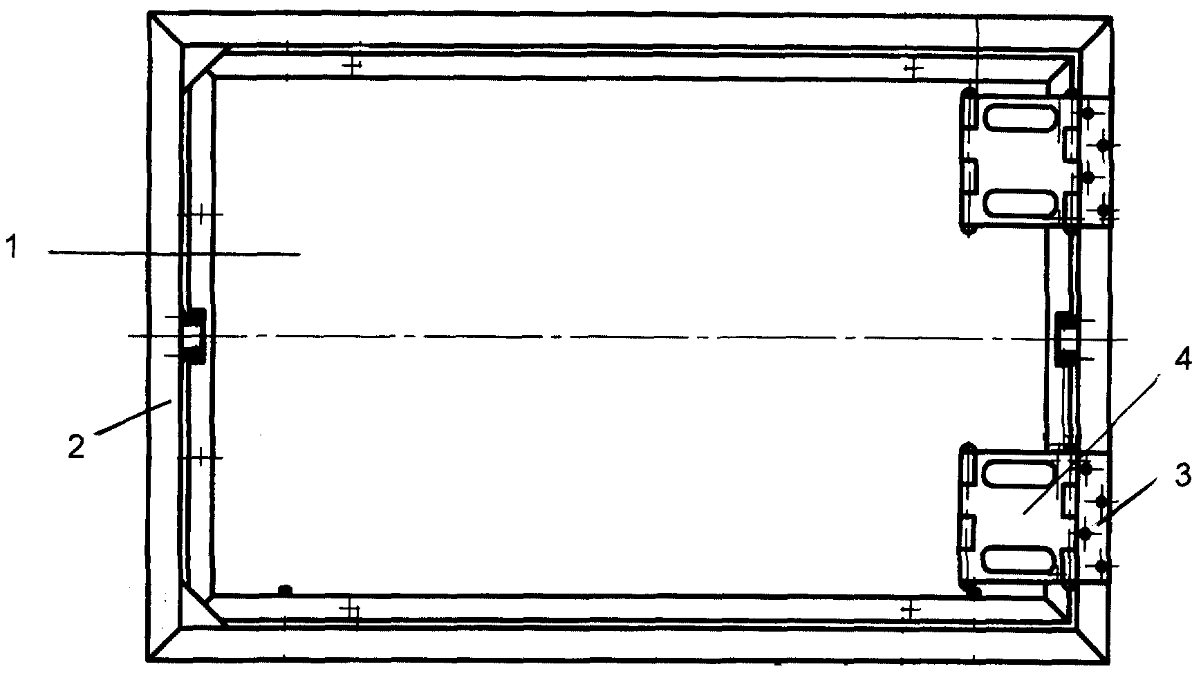
На фиг.1 - вид в плане с обратной стороны на устройство для обеспечения доступа к скрытым инженерным коммуникациям помещения или здания;Figure 1 is a plan view from the back of the device to provide access to hidden utilities of a room or building;
фиг.2 - сечение А-А по фиг.1;figure 2 - section aa in figure 1;
фиг.3 - общий вид на крайнее звено шарнирного трехзвенника;figure 3 is a General view of the extreme link of the articulated three-link;
фиг.4 - то же, что на фиг.3, вид с торца;figure 4 is the same as in figure 3, an end view;
фиг.5 - общий вид на центральное звено шарнирного трехзвенника;5 is a General view of the Central link of the articulated three-link;
фиг.6 - то же, что на фиг.5, вид с торца.Fig.6 is the same as in Fig.5, an end view.
Согласно настоящей полезной модели рассматривается конструктивное оформление технологических проемов в здании или помещении, через которые обеспечивается доступ к инженерным коммуникациям (сантехническим, электрическим, вентиляции и т.п.). Дверца люка может быть отделана любыми материалами и способами, применяемыми для отделки внутренних помещений.According to this utility model, the design of technological openings in a building or building is considered, through which access to utilities (plumbing, electrical, ventilation, etc.) is provided. The hatch door can be finished with any materials and methods used for interior decoration.
Устройство для обеспечения доступа к скрытым инженерным коммуникациям помещения или здания выполнено в виде дверцы 1, шарнирно A device for providing access to hidden engineering communications of a room or building is made in the form of a door 1, hinged
прикрепленной к рамке 2, встроенной в проем. Дверца может иметь любую конструкцию, например, может быть выполнена из металлического листа прямоугольной формы, или иного материала, облицованного снаружи плиткой или декорированного под стиль интерьера. Рамка, которая устанавливается в технологический проем, является базовым элементом устройства и может быть выполнена. Например, прямоугольной формы и металлической, сваренной из профиля с соответствующими элементами ее установки в проем в стене.attached to frame 2 embedded in the opening. The door can be of any design, for example, it can be made of a metal sheet of rectangular shape, or other material, tiled on the outside or decorated in the style of the interior. The frame, which is installed in the technological opening, is the basic element of the device and can be made. For example, a rectangular shape and a metal welded from a profile with the corresponding elements of its installation in the opening in the wall.
Дверца 1 связана с рамкой посредством механизма навески, обеспечивающего возможность ее плоскопараллельного перемещения из открытого положения в проем или из закрытого положения из проема. Механизм навески содержит последовательно шарнирно соединенные между собой жесткие звенья равной или неравной между собой длины (ширины), образующие шарнирный трехзвенник, оси шарниров которых параллельны оси шарниров крепления дверцы.The door 1 is connected to the frame by means of a hinge mechanism, providing the possibility of its plane-parallel movement from an open position to an opening or from a closed position from an opening. The hinge mechanism comprises hard links successively pivotally connected to each other of equal (unequal) length (width), forming a hinged three-link, the hinge axes of which are parallel to the axis of the door hinges.
Шарнирное соединение звеньев между собой выполнено по типу дверных петель, то есть смежные звенья связаны между собой через вертикально установленную ось. На фиг.3, 4 показано конечное (начальное) звено 3 типа петли, а на фиг.5, 6 показано центральное среднее между конечными звеньями 4 типа петли.The hinged connection of the links to each other is made according to the type of door hinges, that is, adjacent links are connected to each other through a vertically mounted axis. Figure 3, 4 shows the final (initial) link 3 of the type of loop, and figure 5, 6 shows the Central average between the final links 4 of the type of loop.
Особенностью предлагаемого устройства является то, что начальное звено 3 трехзвенника шарнирно прикреплено к краю боковой части рамки, конечное звено 3 трехзвенника шарнирно прикреплено к краю дверцы, а между собой эти звенья связаны центральным звеном 4. Трехзвенник представляет собой центральный и два боковых элемента, выполненных в виде вертикально ориентированных пластин, ширина которых меньше их высоты, и каждый из которых связан со смежно расположенным элементом через вертикальную ось, охваченную петлями с образованием петлевого шарнира.A feature of the proposed device is that the initial link 3 of the three-link is pivotally attached to the edge of the side of the frame, the final link 3 of the three-link is pivotally attached to the edge of the door, and these links are interconnected by the central link 4. The three-link is the central and two side elements made in in the form of vertically oriented plates, the width of which is less than their height, and each of which is connected with an adjacent element through a vertical axis, covered by loops with the formation of a loop hinge.
Трехзвенник может быть расположен на середине высоты дверцы. А на фиг.1, 2 показан люк, снабженный дополнительным шарнирным трехзвенником, при этом указанные трехзвенники разнесены по высоте дверцы. Именно при таком исполнении петлевых шарниров обеспечивается возможность исключения провиса нагружзенной дверцы относительно рамки в проеме.The three link can be located in the middle of the height of the door. And figure 1, 2 shows the hatch, equipped with an additional hinged three-link, while these three links are spaced along the height of the door. It is with this design of hinge hinges that it is possible to eliminate the sag of the loaded door relative to the frame in the opening.
При таком исполнении механизма навески обеспечивается возможность поворота дверцы в одну сторону в плоть до ее разворота. При открывании дверцы происходит последовательный разворот каждого последующего звена относительно предыдущего, что позволяет плоскопараллельно вывести дверцу из рамки, сместить ее в сторону и даже повернуть в этом положении, что обеспечивает удобство доступа к скрытым коммуникациям. Так как у двух разнесенных трехзвенников оси шарниров по вертикаль совпадают, то каждый механизм компенсирует изгибные нагрузки, возникающие от веса дверцы на другом трехзвеннике.With this design of the hinge mechanism, it is possible to turn the door in one direction to the flesh before it is turned. When the door is opened, a successive turn of each subsequent link relative to the previous one occurs, which allows the door to be taken out of the frame plane-parallel, move it to the side and even rotate in this position, which provides convenient access to hidden communications. Since the hinge axes coincide vertically for two spaced three-link rings, each mechanism compensates for bending loads arising from the weight of the door on the other three-link.
Настоящая полезная модель промышленно применима, так как может быть реализована в условиях любого машиностроительного производства, так как представляет собой механическую конструкцию шарнирно связанных отдельных элементов.This utility model is industrially applicable, as it can be implemented in the conditions of any machine-building production, as it is a mechanical structure of articulated individual elements.
Claims (3)
Priority Applications (1)
| Application Number | Priority Date | Filing Date | Title |
|---|---|---|---|
| RU2006142147/22U RU62637U1 (en) | 2006-11-29 | 2006-11-29 | DEVICE FOR ACCESS TO HIDDEN INDOOR COMMUNICATIONS ROOMS OR BUILDINGS |
Applications Claiming Priority (1)
| Application Number | Priority Date | Filing Date | Title |
|---|---|---|---|
| RU2006142147/22U RU62637U1 (en) | 2006-11-29 | 2006-11-29 | DEVICE FOR ACCESS TO HIDDEN INDOOR COMMUNICATIONS ROOMS OR BUILDINGS |
Publications (1)
| Publication Number | Publication Date |
|---|---|
| RU62637U1 true RU62637U1 (en) | 2007-04-27 |
Family
ID=38107298
Family Applications (1)
| Application Number | Title | Priority Date | Filing Date |
|---|---|---|---|
| RU2006142147/22U RU62637U1 (en) | 2006-11-29 | 2006-11-29 | DEVICE FOR ACCESS TO HIDDEN INDOOR COMMUNICATIONS ROOMS OR BUILDINGS |
Country Status (1)
| Country | Link |
|---|---|
| RU (1) | RU62637U1 (en) |
-
2006
- 2006-11-29 RU RU2006142147/22U patent/RU62637U1/en not_active IP Right Cessation
Similar Documents
| Publication | Publication Date | Title |
|---|---|---|
| CN1615389A (en) | Overhead garage door with decorative house facade elements | |
| EP2078811A2 (en) | Hinging device for doors of furniture units of vehicles, particularly caravans, motorhomes and boats | |
| US20190323275A1 (en) | Folding barn style door and hardware | |
| JP3244434U (en) | louver structure | |
| RU62638U1 (en) | DEVICE FOR ACCESSING ROOM OR BUILDING | |
| JP5358133B2 (en) | Screen device | |
| CA2312605C (en) | Window gate | |
| KR100767069B1 (en) | Louver type door with deflection prevention device | |
| US3973289A (en) | Door hinge | |
| US6247272B1 (en) | Curved door assembly for workstation | |
| KR101175058B1 (en) | Space saving type opening and closing door | |
| US2279939A (en) | Light control device | |
| JPS6019259Y2 (en) | lower/lower window | |
| JPH0552189U (en) | Lattice body with opening and closing function | |
| RU56443U1 (en) | HATCH REVISION | |
| JPH09303052A (en) | Opening and closing window used for curtain wall | |
| RU65931U1 (en) | DEVICE FOR ACCESS TO HIDDEN ENGINEERING COMMUNICATIONS OF PREMISES AND BUILDINGS | |
| RU76372U1 (en) | HATCH REVISION UNDER FACING WITH FINISHING MATERIALS | |
| RU31811U1 (en) | Steel door | |
| RU59684U1 (en) | DEVICE FOR ACCESS TO HIDDEN ENGINEERING COMMUNICATIONS OF PREMISES AND BUILDINGS | |
| JP4677321B2 (en) | Wooden movable louver | |
| RU79133U1 (en) | HATCH REVISION | |
| RU56926U1 (en) | HATCH REVISION | |
| RU59686U1 (en) | HATCH REVISION UNDER TILES | |
| CN217028560U (en) | Split type adjustable metal door pocket |
Legal Events
| Date | Code | Title | Description |
|---|---|---|---|
| MM1K | Utility model has become invalid (non-payment of fees) |
Effective date: 20081130 |