RU6830U1 - HYDRAULIC VIBRATOR - Google Patents
HYDRAULIC VIBRATOR Download PDFInfo
- Publication number
- RU6830U1 RU6830U1 RU97108253/20U RU97108253U RU6830U1 RU 6830 U1 RU6830 U1 RU 6830U1 RU 97108253/20 U RU97108253/20 U RU 97108253/20U RU 97108253 U RU97108253 U RU 97108253U RU 6830 U1 RU6830 U1 RU 6830U1
- Authority
- RU
- Russia
- Prior art keywords
- spool
- cup
- housing
- glass
- hydraulic vibrator
- Prior art date
Links
- 239000011521 glass Substances 0.000 claims abstract description 13
- 239000012530 fluid Substances 0.000 description 7
- 230000010355 oscillation Effects 0.000 description 4
- 239000006096 absorbing agent Substances 0.000 description 3
- 230000035939 shock Effects 0.000 description 3
- 230000015572 biosynthetic process Effects 0.000 description 2
- 239000007788 liquid Substances 0.000 description 2
- 241000566515 Nedra Species 0.000 description 1
- 230000005540 biological transmission Effects 0.000 description 1
- 230000008878 coupling Effects 0.000 description 1
- 238000010168 coupling process Methods 0.000 description 1
- 238000005859 coupling reaction Methods 0.000 description 1
- 238000002347 injection Methods 0.000 description 1
- 239000007924 injection Substances 0.000 description 1
- 238000009434 installation Methods 0.000 description 1
- 239000002184 metal Substances 0.000 description 1
- 238000005065 mining Methods 0.000 description 1
- 239000002245 particle Substances 0.000 description 1
- 239000004576 sand Substances 0.000 description 1
- 230000002269 spontaneous effect Effects 0.000 description 1
Landscapes
- Geophysics And Detection Of Objects (AREA)
Abstract
1. Гидравлический вибратор золотникового типа, включающий полый корпус, стакан с боковыми окнами и золотник, отличающийся тем, что полый корпус выполнен с боковыми окнами, золотник с пружиной помещен внутрь стакана, стакан установлен в корпусе на резиновых кольцах и уплотнении, а на нижней части стакана закреплен поршень, имеющий уплотнения с корпусом и золотником.2. Вибратор по п.1, отличающийся тем, что стакан зафиксирован в корпусе зажимной гайкой с проходным отверстием под ключ.3. Вибратор по п.1, отличающийся тем, что поршень зафиксирован на стакане стопорным винтом.1. The hydraulic vibrator of the spool type, comprising a hollow body, a cup with side windows and a spool, characterized in that the hollow body is made with side windows, a spool with a spring placed inside the cup, the cup is installed in the housing on rubber rings and a seal, and on the bottom cup fixed piston having seals with housing and spool. 2. The vibrator according to claim 1, characterized in that the glass is fixed in the housing by a clamping nut with a turn-key hole. The vibrator according to claim 1, characterized in that the piston is fixed on the glass with a locking screw.
Description
ГИДРАВЛИЧЕСКИЙ ВИБРАТОРHYDRAULIC VIBRATOR
Полезная модель относится к горной промышленности, а именно - к оборудованию для вибрационного воздействия на призабойную зону пласта (ПЗП) с целью увеличения производительности добывающих и приемистости нагнетательных скважин.The utility model relates to the mining industry, namely, equipment for vibrational impact on the bottom-hole formation zone (PZP) in order to increase production productivity and injectivity of injection wells.
Известен гидравлический вибратор шиберного торцевого типа, включающий полый шпиндель с центральньм каналом, направляющие аппараты, муфту, напорную втулку и щиберный затвор-прерыватель (см., Уметбаев В.Г. Геолого-технические мероприятия при эксплуатации скважин: Справочник рабочего. М., Недра, 1989,215 с, ИЛ.37).. Устройство создает колебания снаружи корпуса, однако частота их велика (сотни Гц) и резонансных явлений, качественно повьппающих результат действия вибратора, не возникает. Как следствие, глубина обработки ПЗП незначительна.Known hydraulic vibrator end-face type, including a hollow spindle with a central channel, guiding devices, a coupling, a pressure sleeve and a gate shutter-interrupter (see, Umetbaev V.G. Geological and technical measures for the operation of wells: Handbook of workers. M., Subsoil , 1989.215 s, IL. 37) .. The device creates vibrations outside the case, but their frequency is high (hundreds of Hz) and resonance phenomena that qualitatively increase the result of the action of the vibrator do not occur. As a result, the processing depth of the PPP is negligible.
Данный гидровибратор имеет невысокую надежность работы в абразивных средах. Кроме того, этот тип гидровибратора может работать только в паре с амортизатором, без которого возможно самопроизвольное отсоединение и поломки труб, подводящих жидкость. Таким образом, функциональные возможности гидровибратора ограничены.This hydraulic vibrator has a low reliability in abrasive environments. In addition, this type of hydraulic vibrator can only work in tandem with a shock absorber, without which spontaneous disconnection and breakage of pipes supplying liquid are possible. Thus, the functionality of the hydraulic vibrator is limited.
Повьппенной надежностью по отношению к предыдущему аналогу обладает известный гидравлический вибратор золотникового типа, выбранный в качестве прототипа (см., Уметбаев В.Г. Геолого-технические мероприятия при эксплуатации скважин: Справочник рабочего. М., Недра, 1989,215 с, ил.37). В корпусе гидровибратора закрепляется ствол в виде стакана с щелевидными прорезями на его образующей и с центральным отверстием внизу, на стволе вращается на щарикоподщипниках золотник также с щелевидными прорезями вдоль образующей. Прорези выполнены под углом к их образующим, направления их в стволе и золотнике противоположны, таким образом, создается как бы турбинное устройство. В стволе выполнены также пусковые отверстия для запуска золотника при перекрытии щелей в стволе.The well-known hydraulic spool type vibrator selected as a prototype possesses increased reliability in relation to the previous analogue (see, Umetbaev V.G. Geological and technical measures for well operation: Handbook of workers. M., Nedra, 1989.215 s, silt. 37). A barrel is fixed in the case of a hydraulic vibrator in the form of a glass with slit-like slots on its generatrix and with a central hole at the bottom; a spool with slit-like slots along the generatrix also rotates on ball-bearings. The slots are made at an angle to their generators, their directions in the barrel and spool are opposite, thus creating a kind of turbine device. In the barrel also made launching holes for starting the spool when overlapping slots in the barrel.
Недостатком данного гидровибратора является возможность заклинивания золотника в случае попадания механических частиц (песка, металлической окалины и пр.), активное изнашивание шариковых подшипников, что особенно вероятно во время спуска гидровибратора на забой скважины. Пусковые отверстия помогают пустить его в работу только на «чистой жидкости.The disadvantage of this hydraulic vibrator is the possibility of jamming the spool in case of mechanical particles (sand, metal scale, etc.), the active wear of ball bearings, which is especially likely during the descent of the hydraulic vibrator to the bottom of the well. Starting holes help put it into operation only on “clean liquid.”
Кроме того, имеет место невысокая эффективность обработки ПЗП, что обусловлено высокой частотой колебаний (от нескольких сотен Гц до 30 КГц), отсутствием резонансных явлений, генерированием колебаний внутри закрытого корпуса.In addition, there is a low efficiency of processing of PZP, which is due to the high frequency of oscillations (from several hundred Hz to 30 KHz), the absence of resonance phenomena, the generation of oscillations inside a closed case.
Настоящая полезная модель имеет своей задачей создание гидравлического вибратора, работающего без амортизатора, с повышенной работоспособностью в абразивных средах, исключающего возможность заклинивания подвижных частей устройства, создающего явления резонанса в затрубном пространстве, что в конечном итоге позволяет увеличить производительность скважин.This utility model has the task of creating a hydraulic vibrator that works without a shock absorber, with increased performance in abrasive media, eliminating the possibility of jamming of the moving parts of the device, which creates resonance phenomena in the annulus, which ultimately allows to increase the productivity of wells.
Технический результат достигается тем, что в гидравлическом вибраторе золотникового типа, включающем полый корпус, стакан с боковыми окнами и золотник, согласно полезной модели , полый корпус вьщолнен с боковыми окнами, золотник с пружиной помещен внутрь стакана, стакан с уплотнением установлен в корпусе на резиновых кольцах, а на нижней части стакана закреплен порщень, имеющий уплотнения с корпусом и золотником. Стакан зафиксирован в корпусе зажимной гайкой с проходным отверстием под ключ. Порщень зафиксирован на стакане стопорным винтом.The technical result is achieved by the fact that in a spool type hydraulic vibrator including a hollow body, a cup with side windows and a spool, according to a utility model, the hollow body is filled with side windows, the spool with a spring is placed inside the cup, the cup with a seal is installed in the housing on rubber rings and on the bottom of the glass fixed piston having seals with a housing and a spool. The glass is fixed in the housing with a clamping nut with a turn-key through hole. The piston is fixed on the glass with a locking screw.
Установка стакана в корпусе на резиновых кольцах обеспечивает функционирование устройства без амортизатора, наличие резиновых колец и уплотнений повыщает работоспособность в абразивных средах и исключает возможность заклинивания, возникновение резонансных явлений в затрубном пространстве обусловлено наличием боковых окон в корпусе гидровибратора и передачей продольных и поперечных колебаний жидкости от золотника с пружиной на стакан и на порщень через резиновые кольца.The installation of the cup in the housing on rubber rings ensures the functioning of the device without a shock absorber, the presence of rubber rings and seals increases the working capacity in abrasive media and eliminates the possibility of jamming, the occurrence of resonance phenomena in the annulus is due to the presence of side windows in the body of the hydraulic vibrator and the transmission of longitudinal and transverse fluid vibrations from the spool with a spring on the glass and on the piston through rubber rings.
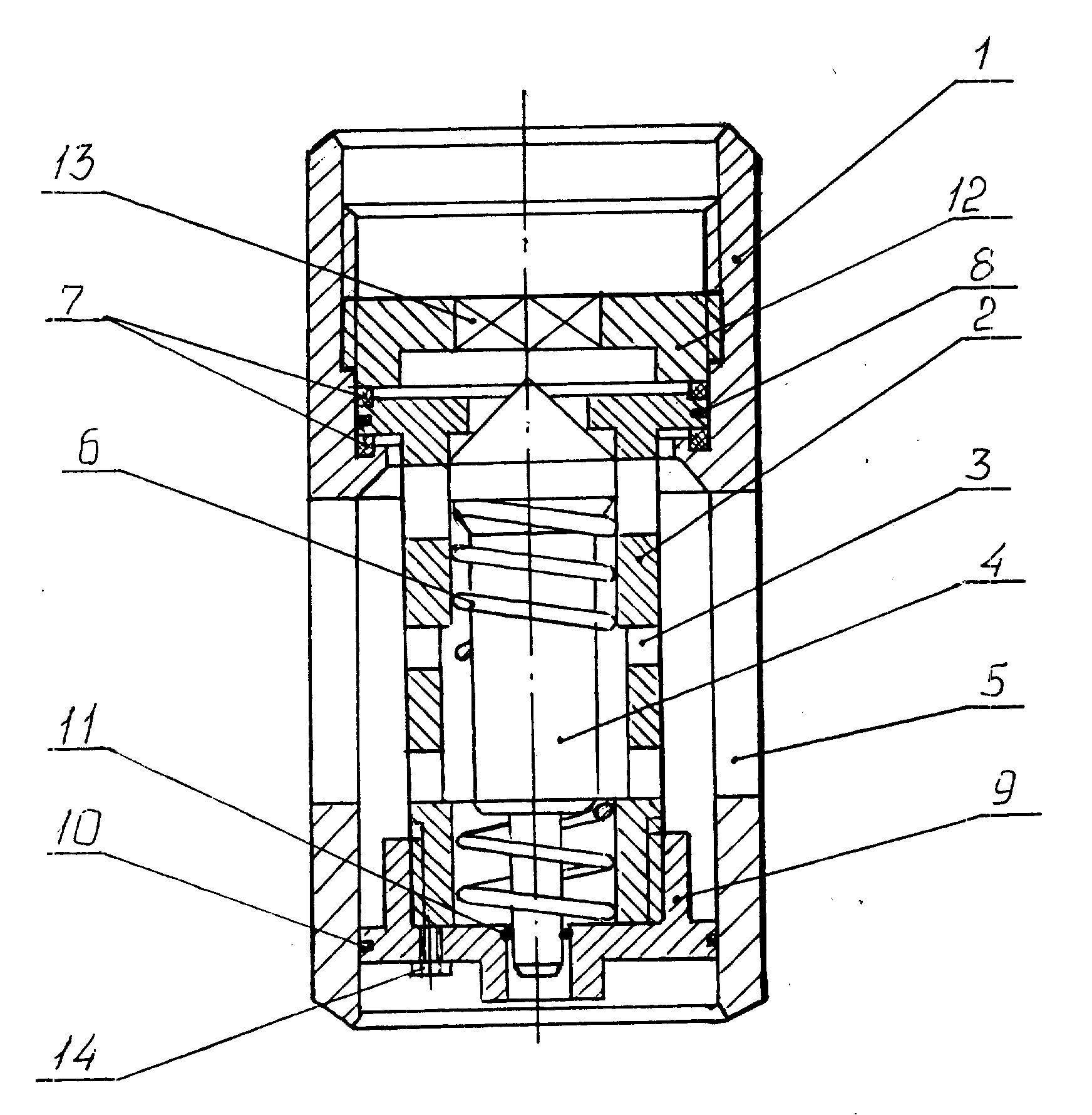
На чертеже представлен разрез гидравлического вибратора.The drawing shows a section of a hydraulic vibrator.
Гидравлический вибратор состоит из полого корпуса 1 с боковыми окнами 5, в котором на резиновых кольцах 7 и уплотнении 8 установлен стакан 2 с боковыми окнами 3. Внутри стакана 2 установлен золотник 4 с пружиной 6. В нижней части стакана 2 размещен порщень 9, на котором установлены уплотнения 10 и 11 с RopnyГидравлический вибратор работает следующим образом. Гидровибратор в сборе опускают на глубину обрабатываемого интервала ПЗП. Закачиваемая рабочая жидкость проходит через полый корпус, проходное отверстие 13 зажимной гайки 12 и давит на золотник 4, отжимая пружину 6. Между золотником 4 и стаканом 2 образуется кольцевой зазор, куда устремляется рабочая жидкость. При этом пружина 6 стремится вернуть золотник в исходное положение и перекрыть кольцевой зазор. В результате противодействия давления рабочей жидкости и силы упругости пружины изменяется величина кольцевого зазора и, как следствие, возникают пульсирующие колебания рабочей жидкости с определенной частотой и амплитудой. Через боковые окна 3 стакана и боковые окна 5 корпуса поток рабочей жидкости с поперечными и продольными колебаниями поступает в затрубное пространство между обсадной колонной и корпусом гидровибратора. С другой стороны, возникающие колебания золотника 4 передаются на порщень 9, в результате чего в подпорщневом пространстве возникают продольные и поперечные колебания рабочей жидкости. Таким образом, в пространстве между корпусом гидровибратора и обсадной колонной собственные колебания накладываются на вынужденные, и возникают резонансные явления с низкой частотой и значительной амплитудой. В результате возникают нарущения в пористой среде ПЗП из-за ее неоднородности, т.е. увеличивается проводимость пласта, а значит и приемистость скважины. От авторов: ГуО/Т) А.В.КоренякоThe hydraulic vibrator consists of a hollow body 1 with side windows 5, in which a glass 2 with side windows 3 is installed on the rubber rings 7 and the seal 8. Inside the glass 2 there is a spool 4 with a spring 6. A piston 9 is placed on the bottom of the glass 2, on which seals 10 and 11 are installed with Ropny The hydraulic vibrator operates as follows. The hydraulic vibrator assembly is lowered to the depth of the processed PZP interval. The injected working fluid passes through the hollow body, the bore 13 of the clamping nut 12 and presses on the spool 4, squeezing the spring 6. An annular gap is formed between the spool 4 and the cup 2, where the working fluid flows. In this case, the spring 6 tends to return the spool to its original position and close the annular gap. As a result of counteracting the pressure of the working fluid and the elastic force of the spring, the size of the annular gap changes and, as a result, pulsating oscillations of the working fluid arise with a certain frequency and amplitude. Through the side windows 3 of the glass and the side windows 5 of the casing, the flow of working fluid with transverse and longitudinal vibrations enters the annulus between the casing and the casing of the hydraulic vibrator. On the other hand, the occurring oscillations of the spool 4 are transmitted to the piston 9, as a result of which longitudinal and transverse vibrations of the working fluid occur in the undergrowth space. Thus, in the space between the body of the hydraulic vibrator and the casing, the natural vibrations are superimposed on the forced vibrations, and resonant phenomena with a low frequency and significant amplitude arise. As a result, disturbances occur in the porous PZP medium due to its heterogeneity, i.e. formation conductivity increases, and therefore well injectivity. From the authors: GuO / T) A.V. Korenyako
Claims (3)
Priority Applications (1)
| Application Number | Priority Date | Filing Date | Title |
|---|---|---|---|
| RU97108253/20U RU6830U1 (en) | 1997-05-22 | 1997-05-22 | HYDRAULIC VIBRATOR |
Applications Claiming Priority (1)
| Application Number | Priority Date | Filing Date | Title |
|---|---|---|---|
| RU97108253/20U RU6830U1 (en) | 1997-05-22 | 1997-05-22 | HYDRAULIC VIBRATOR |
Publications (1)
| Publication Number | Publication Date |
|---|---|
| RU6830U1 true RU6830U1 (en) | 1998-06-16 |
Family
ID=48268841
Family Applications (1)
| Application Number | Title | Priority Date | Filing Date |
|---|---|---|---|
| RU97108253/20U RU6830U1 (en) | 1997-05-22 | 1997-05-22 | HYDRAULIC VIBRATOR |
Country Status (1)
| Country | Link |
|---|---|
| RU (1) | RU6830U1 (en) |
Cited By (2)
| Publication number | Priority date | Publication date | Assignee | Title |
|---|---|---|---|---|
| RU2382872C1 (en) * | 2008-07-29 | 2010-02-27 | Закрытое акционерное общество "Газтехнология" | Hydraulic pulser |
| RU2671242C1 (en) * | 2017-11-02 | 2018-10-30 | Публичное акционерное общество "Татнефть" имени В.Д. Шашина | Hydraulic vibrator |
-
1997
- 1997-05-22 RU RU97108253/20U patent/RU6830U1/en active
Cited By (2)
| Publication number | Priority date | Publication date | Assignee | Title |
|---|---|---|---|---|
| RU2382872C1 (en) * | 2008-07-29 | 2010-02-27 | Закрытое акционерное общество "Газтехнология" | Hydraulic pulser |
| RU2671242C1 (en) * | 2017-11-02 | 2018-10-30 | Публичное акционерное общество "Татнефть" имени В.Д. Шашина | Hydraulic vibrator |
Similar Documents
| Publication | Publication Date | Title |
|---|---|---|
| US8322463B2 (en) | Down hole multiple piston tools operated by pulse generation tools and methods for drilling | |
| US2859733A (en) | Fluid actuated impact tool | |
| US2871943A (en) | Petroleum well treatment by high power acoustic waves to fracture the producing formation | |
| US20050178558A1 (en) | Hydraulic impulse generator and frequency sweep mechanism for borehole applications | |
| CN106639944A (en) | Turbo-type underground hydraulic oscillator | |
| RU2190089C1 (en) | Process of deep perforation of cased wells | |
| US3416613A (en) | Combined rotary and percussion drill utilizing liquid drilling fluid | |
| US2424108A (en) | Hydraulic ram system | |
| CN112627720B (en) | A high-efficiency injection-suction hydraulic impactor | |
| CN114893119A (en) | Hydraulic axial impactor for core drilling | |
| US5816326A (en) | Uphole disposal tool for water producing gas wells | |
| RU6830U1 (en) | HYDRAULIC VIBRATOR | |
| US3507341A (en) | Process and system for rotary drilling with drilling fluid imposed sonic vibrations | |
| RU2205941C2 (en) | Hydromechanical slotting perforator | |
| US4716555A (en) | Sonic method for facilitating the fracturing of earthen formations in well bore holes | |
| RU2274730C2 (en) | Borehole assembly for bottomhole formation zone treatment and impulsive device for borehole assembly | |
| CN117722149B (en) | Hydraulic sliding resistance-changing device | |
| RU2139405C1 (en) | Device for treating deposit by waves | |
| RU2109906C1 (en) | Immersible percussive machine | |
| RU2059803C1 (en) | Device for hydraulic fracturing of formation | |
| SU1758203A1 (en) | Downhole hydraulic hammer drill | |
| RU2268994C2 (en) | Well bottom zone cleaning device | |
| RU2320866C2 (en) | Device for hydroimpulsive well bottom zone treatment | |
| RU2061849C1 (en) | Pulsed borehole perforator | |
| RU2065916C1 (en) | Hole drilling device |