RU72425U1 - BENDING FOR BENDING OF REINFORCED STEEL - Google Patents
BENDING FOR BENDING OF REINFORCED STEEL Download PDFInfo
- Publication number
- RU72425U1 RU72425U1 RU2007134956/22U RU2007134956U RU72425U1 RU 72425 U1 RU72425 U1 RU 72425U1 RU 2007134956/22 U RU2007134956/22 U RU 2007134956/22U RU 2007134956 U RU2007134956 U RU 2007134956U RU 72425 U1 RU72425 U1 RU 72425U1
- Authority
- RU
- Russia
- Prior art keywords
- bending
- worm
- electric motor
- disk
- bed
- Prior art date
Links
- 238000005452 bending Methods 0.000 title claims abstract description 16
- 229910000831 Steel Inorganic materials 0.000 title 1
- 239000010959 steel Substances 0.000 title 1
- 230000005540 biological transmission Effects 0.000 claims abstract description 11
- 229910001294 Reinforcing steel Inorganic materials 0.000 claims abstract description 7
- 238000009434 installation Methods 0.000 claims abstract description 6
- 238000004519 manufacturing process Methods 0.000 abstract description 5
- 239000002184 metal Substances 0.000 abstract description 4
- 230000002787 reinforcement Effects 0.000 description 3
- 238000010586 diagram Methods 0.000 description 1
- 238000000034 method Methods 0.000 description 1
Landscapes
- Bending Of Plates, Rods, And Pipes (AREA)
Abstract
Предлагаемое техническое решение относится к области машиностроения и в частности к станкам для гибки арматуры. В предлагаемой установке для гибки арматурной стали, содержащей станину, диск, выполненный с возможностью вращения, установленный на станине привод диска, включающий в себя электрический двигатель, клиноременную передачу, двухступенчатую зубчатую передачу и червячную передачу, новым является то, что установлен электрический двигатель АИР 100S4 3.0/3000, а червяк в червячной передаче выполнен однозаходным. Благодаря тому, что установлен электрический двигатель АИР 100S4 3.0/3000 с частотой вращения 3000 об/мин, а червяк 9 выполнен однозаходным, снижается металлоемкость при изготовлении станка и трудозатраты при гибке арматурной стали.The proposed technical solution relates to the field of engineering and, in particular, to machines for bending valves. In the proposed installation for bending reinforcing steel containing a bed, a rotatably mounted disk, a disk drive mounted on the bed including an electric motor, V-belt transmission, two-stage gear transmission and worm gear, the new is that the AIR 100S4 electric motor is installed 3.0 / 3000, and the worm in the worm gear is single-shot. Due to the fact that the AIR 100S4 3.0 / 3000 electric motor with a rotation speed of 3000 rpm is installed, and the worm 9 is made single, the metal consumption in the manufacture of the machine and labor costs in bending reinforcing steel are reduced.
Description
Предлагаемое техническое решение относится к области машиностроения и в частности к станкам для гибки арматуры.The proposed technical solution relates to the field of engineering and, in particular, to machines for bending valves.
Известен станок для гибки арматуры СМЖ-173А (прототип), который содержит станину, диск, выполненный с возможностью вращения, установленный на станине привод диска, включающий в себя электрический двигатель АИР 100S4 3.0/1500 с частотой вращения 1500 об/мин, клиноременную передачу, двухступенчатую зубчатую передачу, червячную передачу с двухзаходным червяком (см. книгу: Г.С.Константопуло «Механическое оборудование заводов железобетонных изделий», Москва, Стройиздат, 1993 год. с.162-164, рис.8.14).A known machine for bending reinforcement SMZH-173A (prototype), which contains a frame, a disk made with the possibility of rotation mounted on the frame drive of the disk, including an electric motor AIR 100S4 3.0 / 1500 with a speed of 1500 rpm, V-belt transmission, two-stage gear transmission, a worm gear with a two-way worm (see the book: G.S. Konstantopulo “Mechanical equipment of concrete products factories”, Moscow, Stroyizdat, 1993. p.162-164, Fig. 8.14).
Изготовление такого станка требует больших затрат. Предлагаемое устройство решает задачу уменьшения металлоемкости при изготовлении станка и трудозатрат в процессе гибки арматурной стали. Такой технический результат достигается тем, что в предлагаемой установке для гибки арматурной стали, содержащей станину, диск, выполненный с возможностью вращения, установленный на станине привод диска, включающий в себя электрический двигатель, клиноременную передачу, двухступенчатую зубчатую передачу и червячную передачу, новым является то, что установлен электрический двигатель АИР 100S4 3.0/3000, а червяк в червячной передаче выполнен однозаходным.The manufacture of such a machine is expensive. The proposed device solves the problem of reducing metal consumption in the manufacture of the machine and labor in the process of bending reinforcing steel. This technical result is achieved by the fact that in the proposed installation for bending reinforcing steel containing a bed, a disk made with the possibility of rotation, a disk drive mounted on the bed, including an electric motor, V-belt transmission, two-stage gear transmission and worm gear, is new that an AIR 100S4 3.0 / 3000 electric motor is installed, and the worm in the worm gear is single-start.
Такое выполнение установки обеспечивает снижение металлоемкости при изготовлении станка и трудозатрат при гибке арматурной стали.Such an installation provides a reduction in metal consumption in the manufacture of the machine and labor costs when bending reinforcing steel.
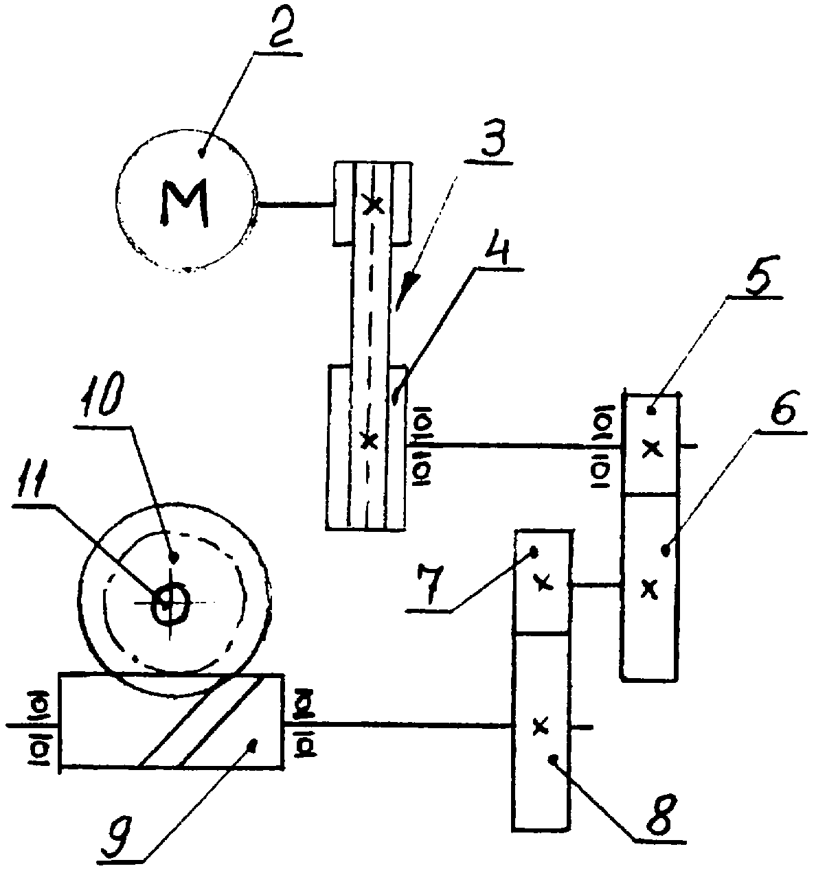
На фиг.1 показана кинематическая схема установки.Figure 1 shows the kinematic diagram of the installation.
На фиг.2 изображен диск для гибки арматуры.Figure 2 shows a disk for bending reinforcement.
Установка включает в себя станину (на рисунках не показана), на которой установлен привод для диска 1, на котором осуществляется гибка арматуры. Привод диска 1 включает в себя электрический двигатель 2 модели АИР 100S4 3.0/3000, клиноременную передачу 3, вал маховика 4, который соединен с двухступенчатой зубчатой передачей, состоящей из колес 5, 6 первой ступени и колес 7, 8 второй ступени, червячную передачу, состоящую из червяка 9 и червячной шестерни 10. На валу 11 шестерни 10 установлен диск 1. На диске 1 имеется центральный палец 12 и изгибающий палец 13. На станине установлен упорный ролик 14. Червяк 9 выполнен однозаходным.The installation includes a bed (not shown in the figures) on which the drive for disk 1 is mounted, on which the fittings are bent. The drive of the disk 1 includes an electric motor 2 of the AIR 100S4 3.0 / 3000 model, a V-belt drive 3, a flywheel shaft 4, which is connected to a two-stage gear transmission consisting of wheels 5, 6 of the first stage and wheels 7, 8 of the second stage, a worm gear, consisting of a worm 9 and a worm gear 10. A disk 1 is mounted on the shaft 11 of the gear 10. On the disk 1 there is a central pin 12 and a bending pin 13. A thrust roller is installed on the bed 14. The worm 9 is single-shot.
Станок работает следующим образом. Арматура укладывается на диск 1 между центральным пальцем 12 и изгибающим пальцем 13 и упорным роликом 14. Включают электрический двигатель 2, вращение с вала которого передается на клиноременную передачу 3. С маховика 4 клиноременной передачи 3 вращение передается на колесо 5 двухступенчатой зубчатой передачи. А с колеса 8 двухступенчатой передачи вращение передается на червяк 9. С червяка 9 вращение передается на червячную шестерню 10, через вал 11 которой вращение передается на диск 1. Диск 1 с помощью изгибающего пальца 13 совершает гибку арматуры.The machine operates as follows. The fittings are placed on the disk 1 between the central pin 12 and the bending pin 13 and the thrust roller 14. An electric motor 2 is turned on, the rotation from the shaft of which is transmitted to the V-belt transmission 3. From the flywheel 4 of the V-belt transmission 3, the rotation is transmitted to the two-speed gear wheel 5. And from the wheel 8 of the two-stage transmission, the rotation is transmitted to the worm 9. From the worm 9, the rotation is transmitted to the worm gear 10, through the shaft 11 of which the rotation is transmitted to the disk 1. The disk 1, using the bending finger 13, bends the reinforcement.
Благодаря тому, что установлен электрический двигатель АИР 100S4 3.0/3000 с частотой вращения 3000 об/мин, а червяк 9 выполнен однозаходным, снижается металлоемкость при изготовлении станка и трудозатраты при гибке арматурной стали.Due to the fact that the AIR 100S4 3.0 / 3000 electric motor with a rotation speed of 3000 rpm is installed, and the worm 9 is made single, the metal consumption in the manufacture of the machine and labor costs in bending reinforcing steel are reduced.
Claims (1)
Priority Applications (1)
| Application Number | Priority Date | Filing Date | Title |
|---|---|---|---|
| RU2007134956/22U RU72425U1 (en) | 2007-09-19 | 2007-09-19 | BENDING FOR BENDING OF REINFORCED STEEL |
Applications Claiming Priority (1)
| Application Number | Priority Date | Filing Date | Title |
|---|---|---|---|
| RU2007134956/22U RU72425U1 (en) | 2007-09-19 | 2007-09-19 | BENDING FOR BENDING OF REINFORCED STEEL |
Publications (1)
| Publication Number | Publication Date |
|---|---|
| RU72425U1 true RU72425U1 (en) | 2008-04-20 |
Family
ID=39454211
Family Applications (1)
| Application Number | Title | Priority Date | Filing Date |
|---|---|---|---|
| RU2007134956/22U RU72425U1 (en) | 2007-09-19 | 2007-09-19 | BENDING FOR BENDING OF REINFORCED STEEL |
Country Status (1)
| Country | Link |
|---|---|
| RU (1) | RU72425U1 (en) |
Cited By (3)
| Publication number | Priority date | Publication date | Assignee | Title |
|---|---|---|---|---|
| RU2551695C1 (en) * | 2014-05-16 | 2015-05-27 | Любовь Алексеевна Агаршева | Small-sized motor drive |
| RU2573386C2 (en) * | 2011-02-18 | 2016-01-20 | Макита Корпорейшн | Electrically-driven tools |
| RU2573585C1 (en) * | 2011-11-22 | 2016-01-20 | Сажем Дефанс Секюрите | Power drive with multiphase motor and control over such drive |
-
2007
- 2007-09-19 RU RU2007134956/22U patent/RU72425U1/en not_active IP Right Cessation
Cited By (3)
| Publication number | Priority date | Publication date | Assignee | Title |
|---|---|---|---|---|
| RU2573386C2 (en) * | 2011-02-18 | 2016-01-20 | Макита Корпорейшн | Electrically-driven tools |
| RU2573585C1 (en) * | 2011-11-22 | 2016-01-20 | Сажем Дефанс Секюрите | Power drive with multiphase motor and control over such drive |
| RU2551695C1 (en) * | 2014-05-16 | 2015-05-27 | Любовь Алексеевна Агаршева | Small-sized motor drive |
Similar Documents
| Publication | Publication Date | Title |
|---|---|---|
| KR20100047144A (en) | Pipe bending machine having an improved movement transmission to a bending die | |
| RU72425U1 (en) | BENDING FOR BENDING OF REINFORCED STEEL | |
| CN103286242B (en) | Parallel multi-head full-automatic reinforcing bar straightening and hoop bending device and use method thereof | |
| CN105156605A (en) | Power conversion device with swing rotation changed into unidirectional rotation | |
| CN201531567U (en) | Planetary gear reducer | |
| CN201956799U (en) | Automobile skylight motor | |
| CN201579311U (en) | Copper pipe straightener | |
| CN205301080U (en) | Bellows resistance to compression test machine | |
| CN2799621Y (en) | Double-drum washing machine | |
| CN202441830U (en) | Speed reducing mechanism for water pump | |
| CN204620920U (en) | Bending machine | |
| CN203528729U (en) | Mechanical transmission labor-saving device | |
| CN2774739Y (en) | Stirring shaft gear driving device for concrete stirrer | |
| CN205209228U (en) | Annular furnace stove bottom rotary driving mechanism | |
| CN214115853U (en) | Cloth rolling device of circular weaving machine | |
| CN202228603U (en) | Gear reducer for lifter | |
| CN204900686U (en) | Force amplifier that energy cycle was shifted | |
| CN101367205A (en) | wedge booster | |
| CN215257633U (en) | A rotary linkage | |
| CN2710785Y (en) | Two curve wheel set and rotating hub type straightener for scaffold tubes | |
| CN206874753U (en) | A kind of PTO of mechanical transfer | |
| CN2886212Y (en) | Twice fluctuation drum-shaped harmonic wave motor reducer | |
| CN208686892U (en) | A kind of actuating unit | |
| CN2856588Y (en) | Reversing speed reducer | |
| CN2666644Y (en) | Tilting discharging device for concrete stirring machine |
Legal Events
| Date | Code | Title | Description |
|---|---|---|---|
| QB1K | Licence on use of utility model |
Effective date: 20080715 |
|
| MM1K | Utility model has become invalid (non-payment of fees) |
Effective date: 20080920 |