RU83301U1 - PUMP UNIT FOR PUMPING HOT NON EXPLOSIVE HAZARDOUS LIQUIDS - Google Patents
PUMP UNIT FOR PUMPING HOT NON EXPLOSIVE HAZARDOUS LIQUIDS Download PDFInfo
- Publication number
- RU83301U1 RU83301U1 RU2008131675/22U RU2008131675U RU83301U1 RU 83301 U1 RU83301 U1 RU 83301U1 RU 2008131675/22 U RU2008131675/22 U RU 2008131675/22U RU 2008131675 U RU2008131675 U RU 2008131675U RU 83301 U1 RU83301 U1 RU 83301U1
- Authority
- RU
- Russia
- Prior art keywords
- unit
- mechanical seal
- pressure
- pipelines
- heat exchanger
- Prior art date
Links
- 238000005086 pumping Methods 0.000 title claims abstract description 12
- 239000007788 liquid Substances 0.000 title claims abstract description 9
- 239000002360 explosive Substances 0.000 title claims abstract description 5
- 231100001261 hazardous Toxicity 0.000 title 1
- 239000012530 fluid Substances 0.000 claims abstract description 7
- XLYOFNOQVPJJNP-UHFFFAOYSA-N water Substances O XLYOFNOQVPJJNP-UHFFFAOYSA-N 0.000 description 7
- 230000015556 catabolic process Effects 0.000 description 2
- 238000007789 sealing Methods 0.000 description 2
- 102000010410 Nogo Proteins Human genes 0.000 description 1
- 108010077641 Nogo Proteins Proteins 0.000 description 1
- 230000015572 biosynthetic process Effects 0.000 description 1
- 238000012856 packing Methods 0.000 description 1
- 125000006850 spacer group Chemical group 0.000 description 1
Landscapes
- Structures Of Non-Positive Displacement Pumps (AREA)
Abstract
1. Насосный агрегат для перекачивания горячих не взрывопожароопасных жидкостей, состоящий из насоса с сальниковой камерой, всасывающим и нагнетательным патрубками и трубопроводами, выносного теплообменника, торцового уплотнения и сети вспомогательных трубопроводов, отличающийся тем, что, с целью безопасной эксплуатации агрегата путем предотвращения выброса горячей жидкости и ее пара в окружающую среду, торцовое уплотнение выполнено тандемного типа, сеть вспомогательных трубопроводов выполнена из трех участков, общего, включающего в себя теплообменник, выполненного с входом для отбора перекачиваемой жидкости в области высокого давления агрегата, и двух последующих участков, одного, выполненного с выходом в сальниковую камеру, и другого, включающего в себя торцовое уплотнение, выполненного с обратным клапаном и с выходом в область низкого давления агрегата. ! 2. Насосный агрегат по п.1, отличающийся тем, что на вспомогательных трубопроводах установлены дросселирующие устройства для управления потоками жидкости, датчики давления и температуры.1. A pumping unit for pumping hot non-explosive fluids, consisting of a pump with stuffing box, suction and discharge pipes and pipelines, an external heat exchanger, a mechanical seal and a network of auxiliary pipelines, characterized in that, for the safe operation of the unit by preventing the release of hot liquid and its vapor into the environment, the mechanical seal is made in tandem type, the network of auxiliary pipelines is made of three sections, a common one including a heat exchanger made with an inlet for the selection of the pumped liquid in the high-pressure area of the unit, and two subsequent sections, one made with an outlet to the stuffing box, and the other including a mechanical seal made with a non-return valve and with an outlet to the low-pressure region unit. ! 2. The pump unit according to claim 1, characterized in that throttling devices for controlling fluid flows, pressure and temperature sensors are installed on auxiliary pipelines.
Description
Полезная модель относится к области насосного оборудования.The utility model relates to the field of pumping equipment.
Известен насосный агрегат СЭ500-70, перекачивающий горячую воду и состоящий из насоса с сальниковой камерой, всасывающим и нагнетательным патрубками, выносного теплообменника и одинарного торцового уплотнения /1/. При помощи встроенного в уплотнение импеллера часть перекачиваемой горячей воды направляется по вспомогательным трубопроводам через холодильник и возвращается в уплотнение, образуя перед уплотнением и в уплотнении зону охлажденной воды. Давление в сальниковой камере и в уплотнении зависит от температуры воды, равно давлению насыщения и может значительно превышать атмосферное.Known pump unit SE500-70, pumping hot water and consisting of a pump with stuffing box, suction and discharge pipes, a remote heat exchanger and a single mechanical seal / 1 /. Using the impeller integrated in the seal, part of the hot water being pumped is sent through auxiliary pipes through the refrigerator and returned to the seal, forming a chilled water zone before the seal and in the seal. The pressure in the stuffing box and in the seal depends on the temperature of the water, is equal to the saturation pressure and can significantly exceed atmospheric pressure.
К недостатку этого агрегата относится не соответствие требованиям безопасной эксплуатации при выхода из строя торцового уплотнения, приводящего к выбросу горячей воды и ее пара в окружающую среду.The disadvantage of this unit is the failure to meet the requirements for safe operation in case of failure of the mechanical seal, leading to the release of hot water and its steam into the environment.
Целью предлагаемой полезной модели насосного агрегата является безопасность эксплуатации при перекачивании горячей не взрывопожароопасной жидкости путем предотвращения выброса ее и пара в окружающую среду.The purpose of the proposed utility model of the pumping unit is the safety of operation when pumping hot non-explosive liquid by preventing the release of it and steam into the environment.
Поставленная цель достигается тем, что в насосном агрегате, состоящем из насоса с сальниковой камерой, всасывающим и нагнетательным патрубками и трубопроводами, выносного теплообменника, торцового уплотнения и сети вспомогательных трубопроводов, торцовое уплотнение выполнено тандемного типа, сеть вспомогательных трубопроводов выполнена из трех участков, общего, включающего в себя теплообменник, выполненного с входом для отбора перекачиваемой жидкости в области высокого давления агрегата, и двух последующих участков, одного, выполненного с выходом в сальниковую камеру, и другого, включающего в себя торцовое уплотнение, выполненного с обратным клапаном и с выходом в область низкого давления агрегата.This goal is achieved by the fact that in a pumping unit consisting of a pump with a stuffing box, suction and discharge pipes and pipelines, a remote heat exchanger, a mechanical seal and a network of auxiliary pipelines, the mechanical seal is made in tandem type, the network of auxiliary pipelines is made of three sections, a common including a heat exchanger made with an inlet for the selection of the pumped liquid in the high pressure area of the unit, and two subsequent sections, one of which Nogo yield the packing box, and the other including a mechanical seal made with the check valve and exit into the low pressure region of the unit.
Для управления потоками жидкости и контроля работы уплотнения в сети трубопроводов могут быть установлены дросселирующие устройства, датчики давления и температуры.To control fluid flows and control the operation of the seal, throttling devices, pressure and temperature sensors can be installed in the pipeline network.
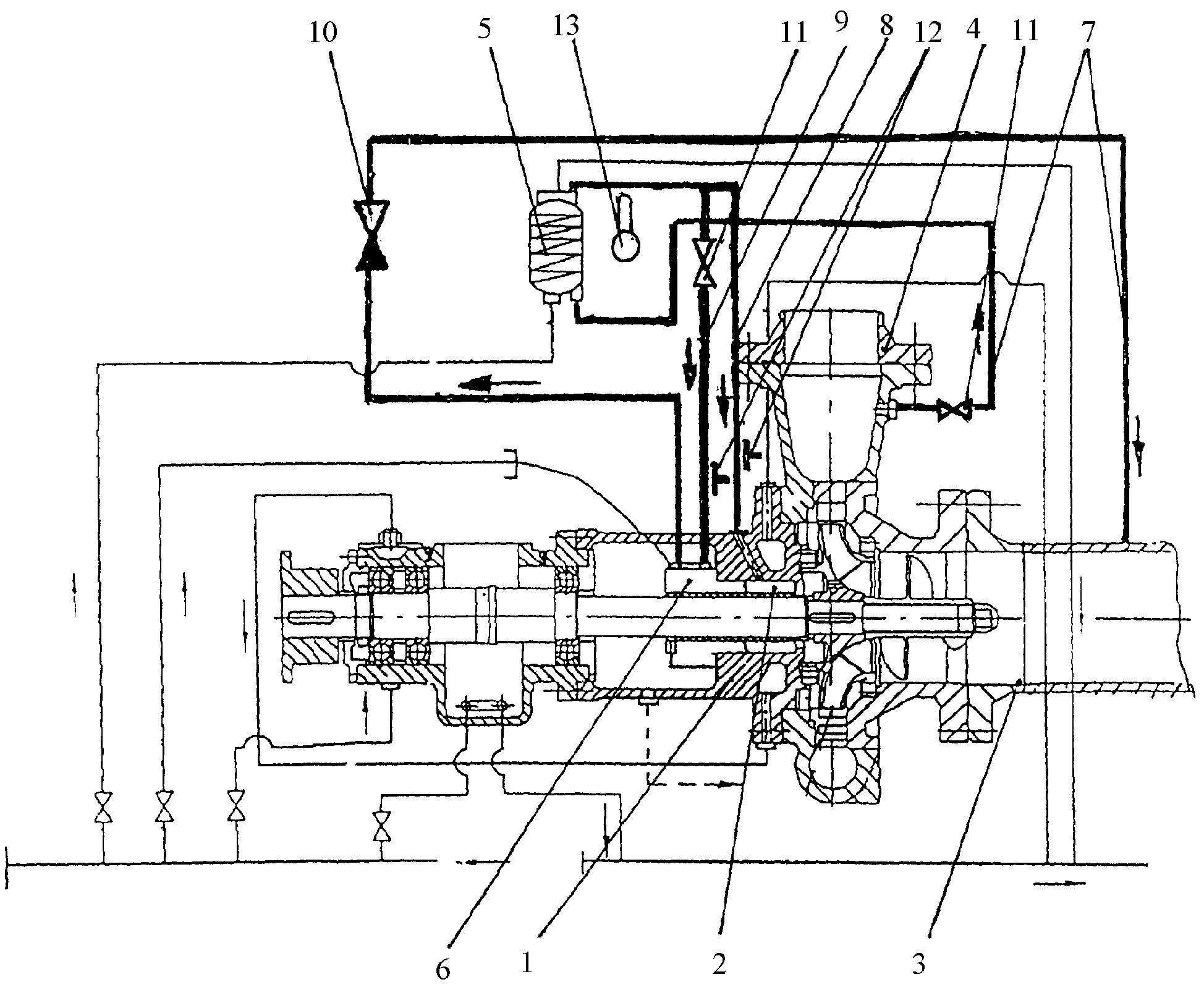
На фиг.1 представлен насосный агрегат, перекачивающий горячие не взрывопожароопасные жидкости. Агрегат имеет: насос 1 с сальниковой камерой 2, всасывающим 3 и нагнетательным 4 патрубками и трубопроводами, выносной теплообменник 5, торцовое тандемного типа уплотнение 6, сеть вспомогательных трубопроводов с общим участком 7, включающим теплообменник 5, и последующими участками 8 и 9 с обратным клапаном 10 и включающим в себя уплотнение 6. На вспомогательных трубопроводах установлены дроссельные устройства 11, датчики давления 12 и датчик температуры 13.Figure 1 shows the pumping unit pumping hot non-explosive fire liquids. The unit has: a pump 1 with a stuffing box 2, a suction 3 and a discharge 4 nozzles and pipelines, an external heat exchanger 5, a mechanical tandem type seal 6, a network of auxiliary pipelines with a common section 7, including a heat exchanger 5, and subsequent sections 8 and 9 with a non-return valve 10 and including a seal 6. Throttle devices 11, pressure sensors 12, and a temperature sensor 13 are installed on auxiliary pipelines.
При работе агрегата перекачиваемая жидкость поступает из области высокого давления агрегата (например, из нагнетательного патрубка 4 насоса 1) через дроссельное устройство 11 под давлением выше давления всасывания в теплообменник 5, где охлаждается до необходимой безопасной температуры, контролируемой датчиком температуры 13. После теплообменника первый поток жидкости по участку 8 вспомогательных трубопроводов поступает в сальниковую камеру 2. Перед входом в камеру контролируется давление датчиком 12, второй поток жидкости по участку 9 с дроссельным устройством 11 поступает через торцовое уплотнение 6 и через обратный клапан 10 в область низкого давления (например, во всасывающий трубопровод 3 агрегата). Перед входом в уплотнение 6 контролируется давление датчиком 12.When the unit is operating, the pumped liquid comes from the high pressure area of the unit (for example, from the discharge pipe 4 of the pump 1) through the throttle device 11 at a pressure higher than the suction pressure to the heat exchanger 5, where it is cooled to the required safe temperature controlled by the temperature sensor 13. After the heat exchanger, the first flow fluid in section 8 of the auxiliary pipelines enters the stuffing box 2. Before entering the chamber, pressure is monitored by the sensor 12, the second fluid flow in section 9 with d the spacer device 11 enters through the mechanical seal 6 and through the check valve 10 to the low pressure region (for example, to the suction pipe 3 of the unit). Before entering the seal 6, the pressure is monitored by the sensor 12.
При нормальной работе насосного агрегата давление в участке 8 устанавливается больше давления в участке 9 вспомогательных трубопроводов.During normal operation of the pump unit, the pressure in section 8 is set more than the pressure in section 9 of the auxiliary pipelines.
При выходе из строя внутренней уплотняющей пары торцового уплотнения перекачиваемый продукта из сальниковой камеры 2 будет поступать в торцовое уплотнение 6 и по участку 9 через обратный клапан 10 поступать во всасывающий трубопровод 3 насосного агрегата и выброса горячей воды и пара в окружающую среду не произойдет.In case of failure of the internal sealing pair of the mechanical seal, the pumped product from the stuffing box 2 will go to the mechanical seal 6 and through section 9 through the check valve 10 to the suction pipe 3 of the pump unit and there will be no release of hot water and steam into the environment.
Изменение давления в участке 8 относительно номинального свидетельствует о поломке внутренней пары уплотнения.The change in pressure in section 8 relative to the nominal indicates a breakdown of the inner pair of the seal.
При поломке внешней уплотняющей пары торцового уплотнения, поступающий по участку 9 трубопровода охлажденный до безопасной температуры продукт будет вытекать в окружающую среду без образования пара. При падении давления в торцовом уплотнении ниже давления во всасывающем трубопроводе насосного агрегата обратный клапан закроется и выброса горячей воды и пара в окружающую среду не произойдет.If the external sealing pair of the mechanical seal breaks down, the product entering the pipeline section 9 cooled to a safe temperature will flow into the environment without steam formation. If the pressure in the mechanical seal drops below the pressure in the suction pipe of the pump unit, the check valve closes and there is no release of hot water and steam into the environment.
Падение давления в участке 9 относительно номинального свидетельствует о поломке внешней пары уплотненияThe pressure drop in section 9 relative to the nominal indicates a breakdown of the outer pair of seals
Claims (2)
Priority Applications (1)
| Application Number | Priority Date | Filing Date | Title |
|---|---|---|---|
| RU2008131675/22U RU83301U1 (en) | 2008-08-01 | 2008-08-01 | PUMP UNIT FOR PUMPING HOT NON EXPLOSIVE HAZARDOUS LIQUIDS |
Applications Claiming Priority (1)
| Application Number | Priority Date | Filing Date | Title |
|---|---|---|---|
| RU2008131675/22U RU83301U1 (en) | 2008-08-01 | 2008-08-01 | PUMP UNIT FOR PUMPING HOT NON EXPLOSIVE HAZARDOUS LIQUIDS |
Publications (1)
| Publication Number | Publication Date |
|---|---|
| RU83301U1 true RU83301U1 (en) | 2009-05-27 |
Family
ID=41023869
Family Applications (1)
| Application Number | Title | Priority Date | Filing Date |
|---|---|---|---|
| RU2008131675/22U RU83301U1 (en) | 2008-08-01 | 2008-08-01 | PUMP UNIT FOR PUMPING HOT NON EXPLOSIVE HAZARDOUS LIQUIDS |
Country Status (1)
| Country | Link |
|---|---|
| RU (1) | RU83301U1 (en) |
-
2008
- 2008-08-01 RU RU2008131675/22U patent/RU83301U1/en not_active IP Right Cessation
Similar Documents
| Publication | Publication Date | Title |
|---|---|---|
| US20110186305A1 (en) | Gas-blanketed piping connections | |
| ATE525609T1 (en) | QUICK COUPLING VALVE, ESPECIALLY FOR PRESSURE FLUIDS | |
| JP2012031856A5 (en) | ||
| US8449264B2 (en) | Method for delivering fluids using a centrifugal pump | |
| EP3256762A2 (en) | Method and device for controlling the oil temperature of an oil-injected compressor installation of a vacuum pump and valve applied in such a device | |
| WO2015122991A3 (en) | Hot gas bypass for two-stage compressor | |
| CN105864093B (en) | Multistage centrifugal high-pressure liquefaction hydrocarbon pumps | |
| MY164751A (en) | Subsea compression assembly | |
| RU83301U1 (en) | PUMP UNIT FOR PUMPING HOT NON EXPLOSIVE HAZARDOUS LIQUIDS | |
| CN106016966A (en) | Industrial refrigerating machine with tubular heater | |
| CN205654551U (en) | Temperature rise control system of high pressure liquefaction hydrocarbon pump | |
| CN106016965A (en) | Working method of industrial refrigerator with tubular heater | |
| RU2337264C2 (en) | Check valve | |
| AR081279A1 (en) | PUMPS FOR FLUIDS AND MONITORING SYSTEMS FOR PUMPS FOR FLUIDS | |
| CN205654588U (en) | Multistage centrifugal high pressure liquefaction hydrocarbon pump | |
| CN108061030B (en) | A clearance air volume adjustment system on a reciprocating compressor | |
| KR102549260B1 (en) | Method and apparatus for pressurizing a compressor system | |
| RU135099U1 (en) | SHELL-TUBULATED HEAT EXCHANGER | |
| CN105889080B (en) | The temperature of high-pressure liquefaction hydrocarbon pump rises control system | |
| RU2269052C2 (en) | Check valve | |
| Paffel | The number one problem in a steam system: Water hammer | |
| RU2555781C1 (en) | Pump unit with control over tightness of twin end seal with bypass pipe | |
| RU2525775C1 (en) | Liquid-propellant rocket engine turbopump unit | |
| CN202707576U (en) | High temperature fireproof leakproof centrifugal pump | |
| RU2016123077A (en) | Device for sealing the inner cavity of a turbomachine |
Legal Events
| Date | Code | Title | Description |
|---|---|---|---|
| MM1K | Utility model has become invalid (non-payment of fees) |
Effective date: 20150802 |