RU91237U1 - CONTROLLED SEMICONDUCTOR COLLECTOR ENGINE SPEED REGULATOR - Google Patents
CONTROLLED SEMICONDUCTOR COLLECTOR ENGINE SPEED REGULATOR Download PDFInfo
- Publication number
- RU91237U1 RU91237U1 RU2008116856/22U RU2008116856U RU91237U1 RU 91237 U1 RU91237 U1 RU 91237U1 RU 2008116856/22 U RU2008116856/22 U RU 2008116856/22U RU 2008116856 U RU2008116856 U RU 2008116856U RU 91237 U1 RU91237 U1 RU 91237U1
- Authority
- RU
- Russia
- Prior art keywords
- phase
- armature
- connect
- designed
- mains
- Prior art date
Links
- 239000004065 semiconductor Substances 0.000 title claims abstract description 13
- 238000004804 winding Methods 0.000 claims abstract description 18
- 230000005284 excitation Effects 0.000 claims abstract description 5
- 230000001105 regulatory effect Effects 0.000 claims abstract description 5
- 230000001276 controlling effect Effects 0.000 description 3
- 238000000034 method Methods 0.000 description 3
- 238000010586 diagram Methods 0.000 description 1
- 230000007717 exclusion Effects 0.000 description 1
Landscapes
- Control Of Ac Motors In General (AREA)
Abstract
Управляемый полупроводниковый регулятор скорости коллекторного двигателя, содержащий последовательно соединенные блок регулировки напряжения, якорь двигателя и обмотку возбуждения, причем выход блока регулировки напряжения предназначен для соединения с фазой питающей сети, а выход обмотки возбуждения - с нулем питающей сети, отличающийся тем, что блок регулировки напряжения выполнен в виде подключенных встречно-параллельно тиристоров, один из которых подсоединен анодом к якорю и катодом предназначен для соединения с фазой питающей сети, а другой катодом подсоединен к якорю и анодом предназначен для соединения с фазой питающей сети, или в виде симистора, один выход которого предназначен для соединения с фазой питающей сети, а другой выход соединен с якорем, или в виде подключенных встречно-параллельно транзисторов, один из которых эмиттером предназначен для соединения с фазой питающей сети, а коллектором связан с якорем, а другой коллектором предназначен для соединения с фазой питающей сети, а эмиттером связан с якорем.A controlled semiconductor collector motor speed controller, comprising a series-connected voltage control unit, a motor armature and an excitation winding, the output of the voltage regulating unit being connected to the mains phase and the excitation winding output having zero mains, characterized in that the voltage regulating unit made in the form of connected in-parallel thyristors, one of which is connected to the armature by the anode and the cathode is designed to connect to the supply phase network, and the other cathode is connected to the armature and the anode is designed to connect to the phase of the mains, or in the form of a triac, one output of which is designed to connect to the phase of the mains, and the other output is connected to the armature, or in the form of connected in-parallel transistors, one of which is designed by the emitter to connect to the phase of the mains, and the collector is connected to the armature, and the other collector is designed to connect to the phase of the mains, and the emitter is connected to the armature.
Description
Предлагаемое изобретение относится к однофазным преобразователям напряжения.The present invention relates to single-phase voltage converters.
Известна однопульсная схема тиристорного низкочастотного преобразователя частоты с питанием от трехфазной сети, образованной из двух однофазных нулевых схем. каждая из которых состоит из двух тиристоров, включенных встречно-параллельно. При этом одна средняя точка каждой схемы предназначена для подключения к фазе питающей сети, а другая средняя точка - для подключения к входам двух обмоток статора, включенных по типу «звезда». Третья обмотка двигателя одним выходом подсоединена к фале питающей сети, а вторым выходом к выходам статорных обмоток двигателя (Глазенко Т.А. Полупроводниковые системы импульсного асинхронного электропривода малой мощности / Т.А.Глазенко. - Ленинград: ЭНЕРГОАТОМИЗДАТ, 1983. - С.59, рис.2-11, №3).Known single-pulse circuit of a thyristor low-frequency frequency converter powered by a three-phase network formed from two single-phase zero circuits. each of which consists of two thyristors connected in counter-parallel. In this case, one midpoint of each circuit is designed to connect to the phase of the supply network, and the other midpoint is to connect to the inputs of two stator windings connected as a "star". The third motor winding is connected with a single output to the halyard of the supply network, and the second output is connected to the outputs of the stator motor windings (Glazenko T.A. Semiconductor systems of a pulsed asynchronous electric drive of low power / T.A. Glazenko. - Leningrad: ENERGOATOMIZDAT, 1983. - P. 59 , fig. 2-11, No. 3).
Основными недостатками данной однопульсной схемы тиристорного низкочастотного преобразователя частоты с питанием от трехфазной сети является отсутствие возможности использования в однофазной сети, вследствие создания при питании трехфазного асинхронного двигателя от однофазной сети в статоре пульсирующего, а не вращающегося поля статора.The main disadvantages of this single-pulse circuit of a thyristor low-frequency frequency converter powered by a three-phase network is the inability to use it in a single-phase network, due to the creation of a three-phase asynchronous motor from a single-phase network when the stator has a pulsating rather than rotating stator field.
Наиболее близким к предлагаемой полезной модели по технической сущности и достигаемому результату (прототипом) является устройство для регулирования скорости вращения коллекторного двигателя, содержащий последовательно соединенные блок регулировки напряжения, выполненный в виде реостата, якорь двигателя и обмотку возбуждения. Один выход реостата предназначен для соединения с фазой питающей сети, а второй выход реостата связан с первым выходом якоря двигателя. Второй выход якоря двигателя соединен с началом обмотки возбуждения, а выход обмотки возбуждения предназначен для соединения с нулем питающей сети. В качестве питающей сети использована однофазная питающая сеть переменного тока для питания трехфазного асинхронного двигателя (Чиликин М.Г. Общий курс электропривода/ М.Г.Чиликин. - М.-Л.: Государственное энергетическое издательство, 1951. - с.48, рис.33).Closest to the proposed utility model in terms of technical nature and the achieved result (prototype) is a device for regulating the speed of rotation of the collector motor, containing a series-connected voltage control unit, made in the form of a rheostat, the motor armature and the field winding. One output of the rheostat is designed to connect to the phase of the supply network, and the second output of the rheostat is connected to the first output of the motor armature. The second output of the motor armature is connected to the beginning of the field winding, and the output of the field winding is designed to connect to zero supply network. As a supply network, a single-phase alternating current supply network was used to power a three-phase asynchronous motor (MG Chilikin. General course of electric drive / MG Chilikin. - M.-L.: State Power Publishing House, 1951. - p. 48, fig. .33).
Основными недостатками описанного устройства для регулирования скорости вращения коллекторного двигателя является сложность плавного регулирования скорости вследствие использования реостата, так как регулировка напряжения, подаваемого на двигатель с помощью реостата, вызывает необходимость использование релейно-контакторной аппаратуры, и поэтому регулировка напряжения является дискретной; пониженная надежность из-за наличия подвижного механического контакта; большие габариты.The main disadvantages of the described device for controlling the rotational speed of the collector motor is the difficulty of smoothly controlling the speed due to the use of a rheostat, since adjusting the voltage supplied to the engine by means of a rheostat necessitates the use of relay-contactor equipment, and therefore the voltage control is discrete; reduced reliability due to the presence of movable mechanical contact; large dimensions.
Предлагаемым изобретением решается задача обеспечения возможности плавною регулирования скоростью, повышения надежности, а также снижения габаритов устройства.The present invention solves the problem of enabling smoothly controlling speed, increase reliability, as well as reduce the dimensions of the device.
Для решения поставленной задачи в управляемом полупроводниковом регуляторе скорости коллекторного двигателя, содержащем последовательно соединенные блок регулировки напряжения, якорь двигателя и обмотку возбуждения, причем выход блока регулировки напряжения предназначен для соединения с фазой питающей сети, а выход обмотки возбуждения - с нулем питающей сети, согласно изобретению блок регулировки напряжения выполнен в виде подключенных встречно-параллельно тиристоров, один из которых подсоединен анодом к якорю и катодом предназначен для соединения с фазой питающей сети, а другой катодом подсоединен к якорю и анодом предназначен для соединения с фазой питающей сети, или в виде симистора, один выход которого предназначен для соединения с фазой питающей сети, а другой выход соединен с якорем, или и виде подключенных встречно-параллельно транзисторов, один из которых эмиттером предназначен для соединения с фазой питающей сети, а коллектором связан с якорем, a другой коллектором предназначен для соединения с фазой питающей сети, а эмиттером связан с якорем.To solve the problem in a controlled semiconductor speed controller of the collector motor, comprising series-connected voltage control unit, the motor armature and the field winding, the output of the voltage control unit is designed to connect to the phase of the supply network, and the output of the field winding is connected to zero supply network, according to the invention the voltage control unit is made in the form of connected in-parallel thyristors, one of which is connected to the armature by the anode and the cathode is intended It is connected to the phase of the mains supply, and the other cathode is connected to the armature and the anode is designed to connect to the phase of the mains, or in the form of a triac, one output of which is designed to connect to the phase of the mains, and the other output is connected to the armature, or connected counter-parallel transistors, one of which is designed by the emitter to connect to the phase of the mains, and the collector is connected to the armature, and the other collector is used to connect to the phase of the mains, and the emitter is connected to the armature.
Плавное регулирование скоростью коллекторного двигателя обусловлено плавным изменением величины подаваемого напряжения на якорь двигателя, гак как предложенная подача управляющих импульсов на встречно-параллельно подключенные тиристоры, или транзисторы, или симистор может изменяться в соответствии с углом открытия тиристоров, симистора или моментом транзисторов в соответствии с проводящей полярностью подаваемого напряжения.The smooth control of the speed of the collector motor is due to a smooth change in the applied voltage to the motor armature, since the proposed supply of control pulses to the in-parallel connected thyristors, or transistors, or a triac can vary in accordance with the opening angle of the thyristors, triac or transistor moment in accordance with the conducting polarity of the applied voltage.
Повышение надежности обусловлено отсутствием подвижного механическою контакта ввиду применения тиристоров, или симистора, или транзисторов.The increase in reliability is due to the lack of movable mechanical contact due to the use of thyristors, or a triac, or transistors.
Снижение габаритов обусловлено исключением реостата и релейно-контакторной аппаратуры управления.The decrease in size is due to the exclusion of the rheostat and relay-contactor control equipment.
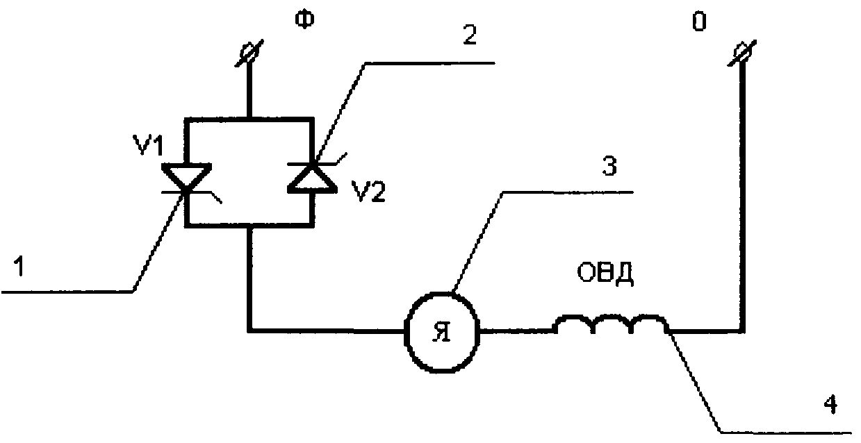
Предлагаемое изобретение поясняется чертежом, где на фиг.1 приведена принципиальная электрическая схема предлагаемого управляемого полупроводниковою регулятора скорости коллекторного двигателя, при выполнении на тиристорах; на фиг.2 то же при выполнении на симисторе; на фиг.3 - то же при выполнении на транзисторах. Кроме того, на чертеже изображено следующее:The invention is illustrated in the drawing, where figure 1 shows a circuit diagram of the proposed controlled semiconductor speed controller of the collector motor, when running on thyristors; figure 2 is the same when executed on the triac; figure 3 is the same when executed on transistors. In addition, the drawing shows the following:
Ф - фаза;F - phase;
0 - ноль;0 is zero;
V1-V2 - тиристоры;V1-V2 - thyristors;
VS - симистор;VS - triac;
VT1-VT2 - транзисторы;VT1-VT2 - transistors;
Я - якорь двигателя;I am the anchor of the engine;
ОВД - обмотка возбуждения двигателя.ATS - the field winding of the engine.
Управляемый полупроводниковый регулятор скорости коллектроного двигателя, содержит блок регулировки напряжения, выполненный в виде подключенных встречно-параллельно тиристоров, один из которых подсоединен анодом к якорю и катодом предназначен для соединения с фазой питающей сети, а другой катодом подсоединен к якорю и анодом предназначен для соединения с фазой питающей сети, или в виде симистора. один выход которого предназначен для соединения с фазой питающей сети, а другой выход - для соединения с якорем, или в виде подключенных встречно-параллельно транзисторов, один из которых эмиттером предназначен для соединения с фазой питающей сети. а коллектором связан с якорем, а другой коллектором предназначен для соединения с фазой питающей сети, а эмиттером связан с якорем. При этом блок регулировки напряжения. якорь двигателя и обмотка возбуждения соединены последовательно. Выход блока регулировки напряжения предназначен для соединения с фазой питающей сети, а выход обмотки возбуждения - с нулем питающей сети.The controlled semiconductor speed controller of the kollektronny motor contains a voltage control unit made in the form of connected in-parallel thyristors, one of which is connected to the armature by the anode and the cathode is designed to connect to the mains phase, and the other is connected to the armature by the cathode and is connected to the anode phase of the supply network, or in the form of a triac. one output of which is designed to connect to the phase of the supply network, and the other output - to connect to the armature, or in the form of connected in-parallel transistors, one of which is emitter designed to connect to the phase of the supply network. and the collector is connected to the anchor, and the other collector is designed to connect to the phase of the supply network, and the emitter is connected to the anchor. In this case, the voltage adjustment unit. motor armature and field winding are connected in series. The output of the voltage control unit is designed to connect to the phase of the supply network, and the output of the field winding is connected to zero of the supply network.
Пример выполнения управляемого полупроводникового регулятора скорости коллекторного двигателя, у которого блок регулировки напряжения выполнен в виде тиристоров. Тиристоры 1, 2 (V1, V2) соединены встречно-параллельно, при этом катод тиристора 2 (V2) и анод тиристора 1 (V1) предназначены для соединения с фазой питающей сети, а анод тиристора 2 (V2) и катод тиристора 1 (V1) подключены к первому выходу якоря 3 двигателя. Второй выход якоря 3 двигателя подключен к обмотке возбуждения 4 двигателя, выход которой подключен к нулю питающей сети.An example of a controlled semiconductor speed controller of a collector motor, in which the voltage control unit is made in the form of thyristors. Thyristors 1, 2 (V1, V2) are connected counter-parallel, while the cathode of thyristor 2 (V2) and the anode of thyristor 1 (V1) are designed to connect to the phase of the supply network, and the anode of thyristor 2 (V2) and the cathode of thyristor 1 (V1 ) are connected to the first output of the armature 3 of the engine. The second output of the armature 3 of the motor is connected to the field winding 4 of the motor, the output of which is connected to zero power supply.
Пример выполнения управляемого полупроводникового регулятора скорости коллекторного двигателя, у которого блок регулировки напряжения выполнен в виде симистора. Один выход симистора 5 (VS) предназначен для соединения с фазой питающей сети, а другой выход подключен к якорю 3 двигателя. Второй выход якоря 3 двигателя подключен к обмотке возбуждения 4 двигателя, выход которой подключен к нулю питающей сети.An example of the execution of a controlled semiconductor speed controller of a collector motor, in which the voltage control unit is made in the form of a triac. One output of the triac 5 (VS) is designed to connect to the phase of the supply network, and the other output is connected to the armature 3 of the motor. The second output of the armature 3 of the motor is connected to the field winding 4 of the motor, the output of which is connected to zero power supply.
Пример выполнения управляемого полупроводникового регулятора скорости коллекторного двигателя, у которого блок регулировки напряжения выполнен в виде транзисторов. Транзисторы 6, 7 (VT1, VT2) соединены встречно-параллельно, при этом коллектор транзистора 6 (VT1) и эмиттер транзистора 7 (VT2) предназначены для соединения с фазой питающей сети, а эмиттер транзистора 6 (VT1) и коллектор транзистора 7 (VT2) подключены к якорю 3 двигателя.. Второй выход якоря 3 двигателя подключен к обмотке возбуждения 4 двигателя, выход которой подключен к нулю питающей сети. Транзисторы 6, 7 (VT1, VT2) могут иметь структуру как n-p-n, так и p-n-p.An example of the execution of a controlled semiconductor speed controller of a collector motor, in which the voltage control unit is made in the form of transistors. Transistors 6, 7 (VT1, VT2) are connected counter-parallel, while the collector of transistor 6 (VT1) and the emitter of transistor 7 (VT2) are designed to connect to the phase of the supply network, and the emitter of transistor 6 (VT1) and the collector of transistor 7 (VT2 ) are connected to the armature 3 of the motor .. The second output of the armature 3 of the motor is connected to the excitation winding 4 of the motor, the output of which is connected to zero of the supply network. Transistors 6, 7 (VT1, VT2) can have both n-p-n and p-n-p structures.
Управляемый полупроводниковый регулятор скорости коллекторного двигателя, у которого блок регулировки напряжения выполнен в виде в виде тиристоров, работаем следующим образом.Managed semiconductor speed controller of the collector motor, in which the voltage regulation unit is made in the form of thyristors, we work as follows.
В положительный полупериод по сигналу управления открывается тиристор 1 (V1), питающее напряжение подводится к якорю 3 двигателя от фазы к нулю. В отрицательный полупериод автоматически закрывается тиристор 1 (V1) и по сигналу управления открывается тиристор 2 (V2), и питающее напряжение подводится к якорю 3 двигателя от нуля к фазе. При прохождении следующих положительной и отрицательной полуволн процесс открытия и закрытия тиристоров 1 (V1), 2 (V2) повторяется.In the positive half-cycle, the thyristor 1 (V1) opens by the control signal, the supply voltage is supplied to the motor armature 3 from phase to zero. In the negative half-cycle, thyristor 1 (V1) is automatically closed and thyristor 2 (V2) opens by the control signal, and the supply voltage is supplied to the armature 3 of the motor from zero to phase. With the passage of the following positive and negative half-waves, the process of opening and closing of thyristors 1 (V1), 2 (V2) is repeated.
Управляемый полупроводниковый регулятор скорости коллекторного двигателя. у которого блок регулировки напряжения выполнен в виде симистора, работает следующим образом.Managed semiconductor commutator speed controller. in which the voltage adjustment unit is made in the form of a triac, operates as follows.
В положительный полупериод по сигналу управления открывается симистор 5 (VS) и питающее напряжение подводится к якорю 3 двигателя от фазы к нулю. При прохождении через ноль питающего напряжения симистор 5 (VS) автоматически закрывается. В отрицательный полупериод по сигналу управления симистор 5 (VS) открывается, и питающее напряжение подводится к якорю 3 двигателя от нуля к фазе. При прохождении следующих положительной и отрицательной полуволн процесс открытия и закрытия симистора 5 повторяется.In the positive half-cycle, the triac 5 (VS) opens by the control signal and the supply voltage is supplied to the motor armature 3 from phase to zero. When passing through zero the supply voltage, the triac 5 (VS) automatically closes. In the negative half-cycle, according to the control signal, the triac 5 (VS) opens, and the supply voltage is supplied to the armature 3 of the motor from zero to phase. With the passage of the following positive and negative half-waves, the process of opening and closing the triac 5 is repeated.
Управляемый полупроводниковый регулятор скорости коллекторного двигателя. у которого блок регулировки напряжения выполнен в виде транзисторов, работает следующим образом.Managed semiconductor commutator speed controller. in which the voltage adjustment unit is made in the form of transistors, operates as follows.
В положительный полупериод при подаче сигнала управления на базу транзистора 6 (VT1) - он открывается, питающее напряжение подводится к якорю 3 двигателя от фазы к нулю. В отрицательный полупериод снимается управляющий импульс с базы транзистора 6 (VT1), и поэтому он закрывается. При подаче сигнала управления на базу транзистора 7 (VT2) - он открывается, и питающее напряжение подводится к якорю 3 двигателя от нуля к фазе. При прохождении следующих положительной и отрицательной полуволн процесс открытия и закрытия транзисторов 6 (VT1), 7 (VT2) повторяется.In the positive half-cycle when the control signal is applied to the base of transistor 6 (VT1) - it opens, the supply voltage is supplied to the motor armature 3 from phase to zero. In the negative half-cycle, the control pulse is removed from the base of transistor 6 (VT1), and therefore it closes. When a control signal is applied to the base of transistor 7 (VT2) - it opens, and the supply voltage is supplied to the armature 3 of the motor from zero to phase. With the passage of the following positive and negative half-waves, the process of opening and closing the transistors 6 (VT1), 7 (VT2) is repeated.
Во всех вышеописанных примерах при работе подача управляющих импульсов на тиристоры, или симистор, или транзисторы - может изменяться функции угла открытия тиристора, сисистора или момента транзисторов в соответствии с полярностью подаваемого напряжения и тем самым плавно изменять величину подаваемого напряжения на якорь двигателя, что, в конечном счете, приводит к плавному изменению скорости двигателя.In all the examples described above, during operation, the supply of control pulses to the thyristors, or triac, or transistors can change the opening angle of the thyristor, system or transistor moment in accordance with the polarity of the applied voltage and thereby smoothly change the amount of applied voltage to the motor armature, which, in ultimately leads to a smooth change in engine speed.
Таким образом, предлагаемое изобретение может обеспечить плавное регулирование скоростью и использоваться в однофазной сети при высоких показателях надежности и малых габаритах.Thus, the present invention can provide smooth speed control and can be used in a single-phase network with high reliability and small dimensions.
Claims (1)
Priority Applications (1)
| Application Number | Priority Date | Filing Date | Title |
|---|---|---|---|
| RU2008116856/22U RU91237U1 (en) | 2008-04-28 | 2008-04-28 | CONTROLLED SEMICONDUCTOR COLLECTOR ENGINE SPEED REGULATOR |
Applications Claiming Priority (1)
| Application Number | Priority Date | Filing Date | Title |
|---|---|---|---|
| RU2008116856/22U RU91237U1 (en) | 2008-04-28 | 2008-04-28 | CONTROLLED SEMICONDUCTOR COLLECTOR ENGINE SPEED REGULATOR |
Publications (1)
| Publication Number | Publication Date |
|---|---|
| RU91237U1 true RU91237U1 (en) | 2010-01-27 |
Family
ID=42122618
Family Applications (1)
| Application Number | Title | Priority Date | Filing Date |
|---|---|---|---|
| RU2008116856/22U RU91237U1 (en) | 2008-04-28 | 2008-04-28 | CONTROLLED SEMICONDUCTOR COLLECTOR ENGINE SPEED REGULATOR |
Country Status (1)
| Country | Link |
|---|---|
| RU (1) | RU91237U1 (en) |
-
2008
- 2008-04-28 RU RU2008116856/22U patent/RU91237U1/en not_active IP Right Cessation
Similar Documents
| Publication | Publication Date | Title |
|---|---|---|
| AU2012358974B2 (en) | System and method for low speed control of polyphase AC machine | |
| CN108390602B (en) | A Direct Predictive Power Control Method for Hybrid Excitation Synchronous Motors | |
| CN110086390A (en) | The generating equipment and packaged type generating set of double voltage gradations are provided | |
| Steigerwald et al. | Analysis of a novel forced-commutation starting scheme for a load-commutated synchronous motor drive | |
| WO2016029764A1 (en) | Speed adjustment device and speed adjustment method for single-phase induction motor | |
| Kancherla et al. | Design of solar-pv operated formal dc-dc converter fed PMBLDC motor drive for real-time applications | |
| RU162848U1 (en) | SEMICONDUCTOR REVERSE DEVICE FOR STARTING AND OPERATING A THREE-PHASE ASYNCHRONOUS MOTOR SUPPLY FROM A SINGLE-PHASE AC NETWORK | |
| CN103414407A (en) | A switched reluctance motor control system device and control method thereof | |
| RU2361357C2 (en) | Device for controlling asynchronous engine in vehicles | |
| RU91237U1 (en) | CONTROLLED SEMICONDUCTOR COLLECTOR ENGINE SPEED REGULATOR | |
| RU107007U1 (en) | SMART START DEVICE FOR SYNCHRONOUS MOTOR WITH ASYNCHRONOUS ACTUATOR | |
| Dodke et al. | Comparison of cuk and buck converter fed electronically commuted motor drive | |
| RU144507U1 (en) | SEMICONDUCTOR CONTROLLED REVERSOR OF SERIAL AC MOTOR | |
| RU167195U1 (en) | ADJUSTABLE AC ELECTRIC DRIVE WITH A COLLECTOR MOTOR FOR POWER SUPPLY FROM SINGLE-PHASE AC VOLTAGE NETWORK | |
| RU2467466C1 (en) | Transistor heteropolar frequency converter that controls speed of synchronous step motor | |
| RU163695U1 (en) | SEMICONDUCTOR REDUCER LED BY A SINGLE-PHASE AC NETWORK | |
| RU215764U1 (en) | Reversible semiconductor device for capacitorless start of a single-phase two-winding asynchronous electric motor | |
| RU138415U1 (en) | ADJUSTABLE WIDE RANGE TRANSISTOR REDUCER FOR THREE-PHASE ASYNCHRONOUS ELECTRIC MOTOR SUPPLY FROM A DC SYSTEM | |
| RU89789U1 (en) | A TRANSISTOR REDUCER FOR POWERING A THREE-PHASE SHORT-CIRCUITED MOTOR, STATOR WINDINGS WHICH ARE CONNECTED BY TYPE "STAR", FROM ONE-PHASE NETWORK | |
| RU109938U1 (en) | FREQUENCY CONVERTER SLAVE BY A SINGLE-PHASE AC NETWORK FOR POWERING A SINGLE-PHASE ASYNCHRONOUS MOTOR | |
| Kumbhar et al. | Design and implementation speed control system of DC Motor using Thyristor in MATLAB Simulink | |
| RU151766U1 (en) | SINGLE-PHASE THREE-PHASE BROADBAND TRANSISTOR FREQUENCY CONVERTER LED BY A SINGLE-PHASE NETWORK | |
| RU157686U1 (en) | WIDES FREQUENCY SPEED CONTROLLER FOR THREE-PHASE ASYNCHRONOUS SHORT-CLOSED ELECTRIC MOTOR | |
| RU2498493C2 (en) | Method for control of thyristors in reversible three-phase thyristor drive and device for its implementation | |
| RU121406U1 (en) | SINGLE-PHASE-THREE-PHASE TRANSISTOR FREQUENCY CONVERTER, LED BY THE NETWORK |
Legal Events
| Date | Code | Title | Description |
|---|---|---|---|
| MM1K | Utility model has become invalid (non-payment of fees) |
Effective date: 20100310 |