RU99464U1 - SHAPED PROFILE FOR SIDES TO THE FRAMES OF THE CONVEYERS AND METAL STRUCTURE ON ITS BASIS - Google Patents
SHAPED PROFILE FOR SIDES TO THE FRAMES OF THE CONVEYERS AND METAL STRUCTURE ON ITS BASIS Download PDFInfo
- Publication number
- RU99464U1 RU99464U1 RU2010128002/11U RU2010128002U RU99464U1 RU 99464 U1 RU99464 U1 RU 99464U1 RU 2010128002/11 U RU2010128002/11 U RU 2010128002/11U RU 2010128002 U RU2010128002 U RU 2010128002U RU 99464 U1 RU99464 U1 RU 99464U1
- Authority
- RU
- Russia
- Prior art keywords
- shaped
- grooves
- main plate
- rectangular
- sides
- Prior art date
Links
- 229910000838 Al alloy Inorganic materials 0.000 claims abstract description 5
- 229910052751 metal Inorganic materials 0.000 claims description 37
- 239000002184 metal Substances 0.000 claims description 37
- 238000004519 manufacturing process Methods 0.000 description 8
- 238000010276 construction Methods 0.000 description 6
- 238000009434 installation Methods 0.000 description 3
- 238000003032 molecular docking Methods 0.000 description 3
- 238000005553 drilling Methods 0.000 description 2
- 238000005516 engineering process Methods 0.000 description 2
- 230000015572 biosynthetic process Effects 0.000 description 1
- 239000011521 glass Substances 0.000 description 1
- 238000007373 indentation Methods 0.000 description 1
- 239000000463 material Substances 0.000 description 1
- 238000011089 mechanical engineering Methods 0.000 description 1
- 238000003801 milling Methods 0.000 description 1
- 235000014101 wine Nutrition 0.000 description 1
Landscapes
- Chain Conveyers (AREA)
Abstract
1. Фасонный профиль для боковин рам конвейеров, выполненный из алюминиевого сплава, содержащий основную пластину, расположенные под углом 90° к ней верхнюю и нижнюю дополнительные пластины, направленные в сторону от ее лицевой поверхности, два углубления вовнутрь на лицевой поверхности основной пластины, выполненные в виде Т-образных пазов, разделяющих основную пластину на верхнюю, среднюю и нижнюю плоскости, при этом боковые стенки пазов параллельны дополнительным пластинам, а две из боковых наружных стенок пазов, обращенные друг к другу, образуют с основной пластиной первый прямоугольный канал, посередине дна которого нанесена продольная технологическая риска, противоположная боковая наружная стенка одного из Т-образных пазов и нижняя дополнительная пластина образуют второй прямоугольный канал, причем верхняя дополнительная пластина установлена на другом краю основной пластины с возможностью образования с боковой наружной стенкой Т-образного паза и основной пластиной третьего прямоугольного канала, при этом фасонный профиль для боковин рам конвейеров выполнен с продольными технологическими рисками, заглубленными по радиусу в виде полуцилиндрической поверхности, отличающийся тем, что нижняя дополнительная пластина выполнена в виде прямоугольного прилива, одна из сторон которого образует с наружной стенкой нижнего из Т-образных пазов и внутренней стороной основной пластины второй прямоугольный канал, причем сторона прилива со стороны, противоположной основной пластине, лежит в одной плоскости с наружной торцевой стенкой этого Т-образного паза, при этом наружные стороны верхней дополнительно� 1. Shaped profile for the sides of the conveyor frames, made of aluminum alloy, containing the main plate, the upper and lower additional plates located at an angle of 90 ° to it, directed away from its front surface, two inward recesses on the front surface of the main plate, made in in the form of T-shaped grooves dividing the main plate into the upper, middle and lower planes, with the side walls of the grooves parallel to the additional plates, and two of the side outer walls of the grooves facing each other form the first rectangular channel with the main plate, in the middle of the bottom of which a longitudinal technological risk is applied, the opposite lateral outer wall of one of the T-grooves and the lower additional plate form the second rectangular channel, and the upper additional plate is mounted on the other edge of the main plate with the possibility of the lateral outer wall of the T-groove and the main plate of the third rectangular channel, while the shaped profile for the sides of the conveyor frames is made with native technological risks radially recessed in the form of a semi-cylindrical surface, characterized in that the lower additional plate is made in the form of a rectangular tide, one side of which forms a second rectangular channel with the outer wall of the lower T-grooves and the inner side of the main plate, the side the tide from the side opposite the main plate lies in the same plane with the outer end wall of this T-shaped groove, while the outer sides of the upper
Description
Полезная модель относится к машиностроению и может быть использована при изготовлении металлоконструкций рам пластинчатых конвейеров применяемых в пищевой, фармацевтической, стеклотарной, и других отраслях промышленности.The utility model relates to mechanical engineering and can be used in the manufacture of metal structures of plate conveyor frames used in food, pharmaceutical, glass, and other industries.
Известны различные типы пластинчатых конвейеров, применение которых обосновано их конструктивными особенностями - возможностью создания на их основе различные разветвленные транспортные системы.Various types of plate conveyors are known, the use of which is justified by their design features - the ability to create various branched transport systems on their basis.
В настоящее время мировая тенденция в технической политике известных фирм, выпускающих конвейеры и конвейерные составляющие, состоит, в частности, в изготовлении металлоконструкций рам конвейеров с применением боковин из специальных профилей выполненных из алюминиевых сплавов.Currently, the global trend in the technical policy of well-known companies producing conveyors and conveyor components consists, in particular, in the manufacture of metal structures for conveyor frames using sidewalls from special profiles made of aluminum alloys.
Как правило, каждый профиль производства этих фирм предназначен для определенного типоразмера рамы конвейера. Профили выполнены с Т-образными пазами, предназначенными для размещения и фиксации гаек различных болтовых соединений конвейера при установки и креплении модульных секций, различных узлов и элементов.As a rule, each production profile of these companies is designed for a specific size of the conveyor frame. The profiles are made with T-shaped grooves intended for placement and fixing of nuts of various bolted joints of the conveyor during installation and fastening of modular sections, various units and elements.
Наиболее близким аналогом предлагаемой полезной модели является патент РФ №60503 по заявке №2005134699 «Фасонный профиль для боковин рам конвейеров и металлоконструкция на его основе».The closest analogue of the proposed utility model is the patent of the Russian Federation No. 60503 according to the application No. 2005134699 "Shaped profile for the sides of conveyor frames and the metal structure based on it."
Известная полезная модель характеризуется, как:A known utility model is characterized as:
Фасонный профиль для боковин рам конвейеров, выполненный из алюминиевого сплава, содержащий основную пластину, расположенные под углом 90° к ней верхнюю и нижнюю дополнительные пластины, направленные в сторону от ее лицевой поверхности, два углубления во внутрь на лицевой поверхности основной пластины, выполненные в виде Т-образных пазов, разделяющих основную пластину на верхнюю, среднюю и нижнюю плоскости, при этом боковые стенки пазов параллельны дополнительным пластинам, а две из боковых наружных стенок пазов обращенные друг к другу образуют с основной пластиной первый прямоугольный канал посередине дна, которого нанесена продольная технологическая риска, противоположная боковая наружная стенка одного из Т-образных пазов и нижняя дополнительная пластина образует второй прямоугольный канал, причем верхняя дополнительная пластина установлена на другом краю основной пластины с возможностью образования с боковой наружной стенкой Т-образного паза и основной пластиной третьего прямоугольного канала, при этом фасонный профиль для боковин рам конвейеров выполнен с продольными технологическими рисками, заглубленными по радиусу в виде полуцилиндрической поверхности.Shaped profile for the sides of the conveyor frames made of aluminum alloy, containing the main plate, the upper and lower additional plates located at an angle of 90 ° to it, directed away from its front surface, two indentations inward on the front surface of the main plate, made in the form T-grooves dividing the main plate into the upper, middle and lower planes, with the side walls of the grooves parallel to the additional plates, and two of the side outer walls of the grooves facing each other about the first rectangular channel is formed with the main plate in the middle of the bottom, which carries a longitudinal technological risk, the opposite lateral outer wall of one of the T-grooves and the lower additional plate forms a second rectangular channel, with the upper additional plate mounted on the other edge of the main plate with the possibility of formation from the side the outer wall of the T-groove and the main plate of the third rectangular channel, while the shaped profile for the sides of the conveyor frames is made with Dolni technological risk, recessed radially in the form of a semicylindrical surface.
Причем металлоконструкция, выполнена на основе двух фасонных профилей для боковин рам конвейеров установленных внутренними сторонами друг к другу и жестко скрепленных между собой через дистанционные связи расположенные по их длине.Moreover, the metal structure is made on the basis of two shaped profiles for the sidewalls of the conveyor frames installed by the inner sides to each other and rigidly fastened to each other through remote connections located along their length.
Известная конструкция имеет ряд недостатков. Для установки пластмассовых направляющих ветви цепи необходима фрезеровка верхней дополнительной пластины. Профиль имеет недостаточную прочность для применения его в рамах многорядных конвейеров (накопительные столы). Варианты известных металлоконструкций не соответствуют требованиям приводных секций рам конвейеров модульных конструкций.The known design has several disadvantages. To install the plastic chain guide rails, milling of the upper accessory plate is necessary. The profile has insufficient strength for use in multi-row conveyor frames (storage tables). Variants of the known metal structures do not meet the requirements of the drive sections of the conveyor frames of modular structures.
Цель предлагаемой полезной модели усовершенствование конструкции, технологии изготовления и создание универсального фасонного профиля для боковин рам конвейеров и металлоконструкций на его основе для промежуточных, приводных и других секций конвейеров при внедрении модульной сборки.The purpose of the proposed utility model is the improvement of the design, manufacturing technology and the creation of a universal shaped profile for the sidewalls of conveyor frames and metal structures based on it for intermediate, drive and other sections of conveyors when introducing a modular assembly.
Указанная цель достигается тем, что нижняя дополнительная пластина выполнена в виде прямоугольного прилива, одна из сторон которого образует с наружной стенкой нижнего из Т-образных пазов и внутренней стороной основной пластины второй прямоугольный канал, причем сторона прилива со стороны противоположной от основной пластины лежит в одной плоскости с наружной торцевой стенкой этого Т-образного паза, при этом наружные стороны верхней дополнительной пластины и днища нижнего Т-образного паза оснащены упорами.This goal is achieved by the fact that the lower additional plate is made in the form of a rectangular tide, one side of which forms a second rectangular channel with the outer wall of the lower of the T-grooves and the inner side of the main plate, and the side of the tide from the side opposite to the main plate lies in one planes with the outer end wall of this T-groove, while the outer sides of the upper additional plate and the bottom of the lower T-groove are equipped with stops.
Указанная цель достигается тем, что технологические риски расположены с внутренней стороны профиля посередине днища Т-образных пазов, а также в прямоугольных каналах, а также на лицевой стороне профиля на верхней, средней и нижней плоскостях и внутренней стороне прямоугольного прилива.This goal is achieved by the fact that technological risks are located on the inner side of the profile in the middle of the bottom of the T-grooves, as well as in rectangular channels, as well as on the front side of the profile on the upper, middle and lower planes and the inner side of the rectangular tide.
Кроме того, указанная цель достигается тем, что металлоконструкция, выполнена на основе двух фасонных профилей для боковин рам конвейеров установленных внутренними сторонами друг к другу и жестко скрепленных между собой через дистанционные связи расположенные по их длинне, при этом дистанционные связи расположены по длине фасонных профилей боковин в два ряда так, что один ряд расположен в верхнем прямоугольном канале, а второй на прямоугольном приливе и наружной торцевой стенки нижнего Т-образного паза каждого из фасонных профилей боковин и жестко скреплены с ними метизами.In addition, this goal is achieved by the fact that the metal structure is made on the basis of two shaped profiles for the sidewalls of the conveyor frames installed by the inner sides to each other and rigidly fastened to each other through distance connections located along their length, while the distance connections are located along the length of the shaped profiles of the sidewalls in two rows so that one row is located in the upper rectangular channel, and the second on the rectangular tide and the outer end wall of the lower T-groove of each of the shaped side profiles wines and rigidly attached to them hardware.
Указанная цель достигается тем, что дистанционные связи, выполнены в виде прямоугольных фасонных профилей с Т-образными пазами и прилегающих к фасонным профилям боковин длинной стороной вдоль них.This goal is achieved by the fact that remote communications are made in the form of rectangular shaped profiles with T-shaped grooves and adjacent to the shaped profiles sidewalls with the long side along them.
Указанная цель достигается тем, что дистанционные связи, выполнены в виде прямоугольных фасонных профилей с Т-образными пазами и прилегающих к фасонным профилям боковин короткой стороной вдоль них.This goal is achieved by the fact that remote communications are made in the form of rectangular shaped profiles with T-grooves and adjacent to the shaped profiles of the sidewalls with the short side along them.
Указанная цель достигается тем, что дистанционные связи, выполнены в виде квадратных фасонных профилей с Т-образными пазами.This goal is achieved by the fact that remote communications are made in the form of square shaped profiles with T-shaped grooves.
Указанная цель достигается тем, что две дистанционные связи, выполнены из прямоугольных фасонных профилей с Т-образными пазами, и отверстиями под метизы по боковым стороначто две дистанционные связи, выполнены из м, причем установлены на торцах фасонных профилей.This goal is achieved by the fact that two distance connections are made of rectangular shaped profiles with T-grooves, and holes for hardware on the side sides are two distance connections made of m, and are installed on the ends of the shaped profiles.
Указанная цель достигается тем, квадратных фасонных профилей с Т-образными пазами, и отверстиями под метизы по боковым сторонам, причем установлены на торцах фасонных профилей.This goal is achieved by the fact that square shaped profiles with T-shaped grooves, and holes for hardware on the sides, and mounted on the ends of the shaped profiles.
Указанная цель достигается тем, что две дистанционные связи, выполнены из квадратного проката, причем по боковым сторонам имеют отверстия под метизы и установлены в два ряда с внутренней стороны профиля на днищах Т-образных пазов по торцам фасонных профилей.This goal is achieved by the fact that two distance connections are made of square metal, and on the sides there are holes for hardware and are installed in two rows from the inside of the profile on the bottoms of the T-grooves at the ends of the shaped profiles.
Указанная цель достигается тем, что три дистанционные связи, выполнены из квадратного проката, причем по боковым сторонам имеют отверстия под метизы и установлены по торцам фасонных профилей, при этом одна связь установлена в верхнем прямоугольном канале, вторая в среднем прямоугольном канале, а третья на прямоугольном приливе.This goal is achieved by the fact that three distance connections are made of square rolled products, and on the sides there are holes for hardware and installed at the ends of shaped profiles, with one connection installed in the upper rectangular channel, the second in the middle rectangular channel, and the third on the rectangular the tide.
Полезная модель фасонного профиля боковин рам конвейеров и металлоконструкция на его основе, как частные случаи выполнения, поясняются чертежами.A useful model of the shaped profile of the sidewalls of the conveyor frames and the metal structure based on it, as special cases of execution, are illustrated by the drawings.
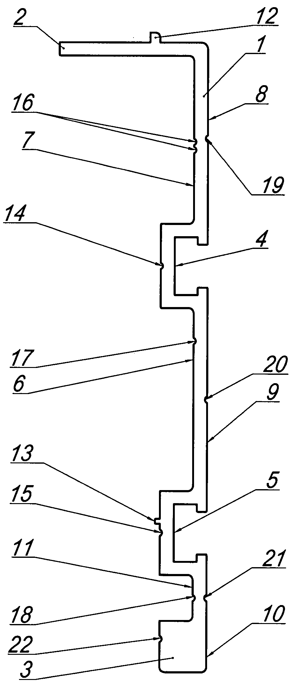
На фиг.1 изображен вид с боку на предлагаемый фасонный профиль для боковин рам конвейеров.Figure 1 shows a side view of the proposed shaped profile for the sides of the conveyor frames.
На фиг.2. изображен упрощенный первый частный случай металлоконструкции на основе двух предлагаемых фасонных профилей. Дистанционные связи выполнены из прямоугольного фасонного профиля. Вид сверху.In figure 2. A simplified first particular case of a metal structure is depicted on the basis of two proposed shaped profiles. Remote communications are made of a rectangular shaped profile. View from above.
На фиг.3. разрез по А-А на фиг.2 (повернуто)In figure 3. section along AA in figure 2 (rotated)
На фиг.4. изображен упрощенный первый частный случай металлоконструкции на основе двух предлагаемых фасонных профилей. Дистанционные связи выполнены из квадратного фасонного профиля. Вид сверху.In figure 4. A simplified first particular case of a metal structure is depicted on the basis of two proposed shaped profiles. Remote communications are made of square shaped profile. View from above.
На фиг.5. разрез по Б-Б на фиг.4. (повернуто)5. section along BB in figure 4. (rotated)
На фиг.6. изображен упрощенный второй частный случай выполнения металлоконструкции на основе двух фасонных профиля для боковин рам конвейеров. Дистанционные связи на торце выполнены из квадратного фасонного профиля с боковыми отверстиями и установлены в два ряда. Вид сверху.In Fig.6. A simplified second particular case of metal construction on the basis of two shaped profiles for the sides of conveyor frames is shown. Remote communications at the end are made of a square shaped profile with side openings and are installed in two rows. View from above.
На фиг.7 разрез по Д-Д на фиг.10 (повернуто)In Fig.7 a section along DD in Fig.10 (rotated)
На фиг.8. изображен упрощенный третий частный случай выполнения металлоконструкции на основе двух предлагаемых фасонных профилей. Дистанционные связи на торце выполнены из квадратного проката с боковыми отверстиями и установлены в два ряда. Вид сверху.On Fig. A simplified third particular case of metal construction on the basis of two proposed shaped profiles is shown. Remote communications at the end are made of square metal with side holes and are installed in two rows. View from above.
На фиг.9. разрез по В-В на фиг.6. (повернуто)In Fig.9. section along BB in Fig.6. (rotated)
На фиг.10. изображен упрощенный четвертый частный случай выполнения металлоконструкции на основе двух фасонных профиля для боковин рам конвейеров. На торце дистанционные связи дистанционные связи выполнены из квадратного проката с отверстиями и установлены в три ряда. Вид сверху.10. A simplified fourth particular case of metal construction on the basis of two shaped profiles for the sides of conveyor frames is shown. At the end of the remote communications remote communications are made of square metal with holes and installed in three rows. View from above.
На фиг.11 разрез по Г-Г на фиг.8. (повернуто)In Fig.11 section along G-G in Fig.8. (rotated)
Пример выполнения фасонного профиля для боковин рам конвейеров представлен на фиг.1. Фасонный профиль состоит из основной пластины 1, дополнительной пластины 2 и прямоугольного прилива 3. Два углубления, выполнены внутрь фасонного профиля для боковин рам конвейеров в виде Т-образных пазов верхнего 4 и нижнего 5 расположены на лицевой поверхности основной пластины 1.An example of the execution of the shaped profile for the sides of the frames of the conveyors is presented in figure 1. The shaped profile consists of a main plate 1, an additional plate 2 and a rectangular tide 3. Two recesses are made inside the shaped profile for the sides of the conveyor frames in the form of T-shaped grooves of the upper 4 and lower 5 located on the front surface of the main plate 1.
Прямоугольный канал 6 образован наружными боковыми стенками пазов 4 и 5 и внутренней стороной основной пластины 1. На днища канала 6 нанесена продольная технологическая риска 17.The rectangular channel 6 is formed by the outer side walls of the grooves 4 and 5 and the inner side of the main plate 1. On the bottom of the channel 6 is applied a longitudinal technological risk 17.
В нижней части фасонного профиля для боковин рам конвейеров одна из сторон прямоугольного прилива 3 образует с наружной стенкой нижнего из Т-образных пазов 5 и внутренней стороной основной пластины 1 второй прямоугольный канал 11.In the lower part of the shaped profile for the sides of the conveyor frames, one of the sides of the rectangular tide 3 forms with the outer wall of the lower of the T-grooves 5 and the inner side of the main plate 1 a second rectangular channel 11.
Боковая наружная стенка верхнего Т-образного паза 5 образует с основной 1 и дополнительной пластиной 3 третий прямоугольный канал 7. Лицевая поверхность основной пластины 1 разделена пазами 4 и 5 на три плоскости - верхнею 8, среднею 9 и нижнею 10.The lateral outer wall of the upper T-shaped groove 5 forms with the main 1 and additional plate 3 a third rectangular channel 7. The front surface of the main plate 1 is divided by grooves 4 and 5 into three planes - upper 8, middle 9 and lower 10.
Лицевая и внутренняя поверхности фасонного профиля на фиг.6 имеют технологические риски, заглубленные по радиусу в виде части цилиндрической поверхности.The front and inner surfaces of the shaped profile in Fig.6 have technological risks buried along the radius as part of a cylindrical surface.
С внутренней стороны профиля посередине днищ Т-образных пазов расположены риски 14 и 15.On the inside of the profile in the middle of the bottoms of the T-grooves are risks 14 and 15.
Риски 16, 17 и 18. расположены в прямоугольных каналах 7, 6 и 11. На лицевой стороне пластины 1 на ее верхней 8, средней 9 и нижней 10 плоскостях риски 19, 20, 21.Risks 16, 17 and 18. are located in rectangular channels 7, 6 and 11. On the front side of the plate 1 on its upper 8, middle 9 and lower 10 planes, risks 19, 20, 21.
На внутренней стороне прямоугольного прилива 3 расположена риска 22. Наружные стороны дополнительной пластины 2 и днища нижнего Т-образного паза оснащены соответственно упорами 12 и 13.On the inner side of the rectangular tide 3 there is a risk 22. The outer sides of the additional plate 2 and the bottom of the lower T-shaped groove are equipped with stops 12 and 13, respectively.
Материал, из которого выполнен фасонный профиль боковин рам конвейеров: -деформируемый алюминиевый сплав для получения изделий методом прессования.The material from which the shaped profile of the sidewalls of the conveyor frames is made: -deformable aluminum alloy to obtain products by pressing.
На фиг.2-5 показан, как пример, первый частный случай металлоконструкции на основе двух фасонных профилей для боковин рам конвейеров с дистанционными связями 24 или 25 расположенными в два ряда по длине боковин, выполненными из различных фасонных профилей.Figure 2-5 shows, as an example, the first special case of metal structures based on two shaped profiles for the sides of conveyor frames with distance connections 24 or 25 arranged in two rows along the length of the side walls made of different shaped profiles.
Металлоконструкция состоит из двух фасонных профилей для боковин рам конвейеров фиг.1 повернутых друг к другу своими внутренними поверхностями. Расстояние между фасонными профилями боковин определяется размером дистанционных связей 24 или 25 и зависит от числа транспортирующих цепей.The metal structure consists of two shaped profiles for the sidewalls of the conveyor frames of Fig. 1, turned to each other by their inner surfaces. The distance between the shaped profiles of the sidewalls is determined by the size of the distance ties 24 or 25 and depends on the number of transporting chains.
Связи 24 распложены в два ряда в прямоугольных каналах фасонных профилей для боковин рам конвейеров по их длине и жестко скреплены с профилями при помощи метизов 26. Причем один ряд дистанционных связей 24 или 25 расположен в верхнем прямоугольном канале 7 (фиг.1), а второй на прямоугольном приливе 3 и наружной торцевой стенке нижнего Т-образного паза 5. Крепление метизами производится через отверстия, которые сверлятся в фасонных профилях по технологическим рискам 16 и 18 или 21 (фиг.1).The ties 24 are arranged in two rows in rectangular channels of shaped profiles for the sides of the conveyor frames along their length and are rigidly fastened to the profiles with the help of hardware 26. Moreover, one row of distance links 24 or 25 is located in the upper rectangular channel 7 (Fig. 1), and the second on a rectangular tide 3 and the outer end wall of the lower T-shaped groove 5. Fastening with hardware is made through holes that are drilled in shaped profiles according to technological risks 16 and 18 or 21 (Fig. 1).
Риски нанесены на внутренней поверхности профиля также для возможности одновременного сверления отверстий на двух соединенных друг с другом лицевых сторонах фасонных профилей боковин.Risks are applied on the inner surface of the profile also for the possibility of simultaneous drilling of holes on two connected to each other front sides of the shaped profiles of the sidewalls.
Дистанционные связи 24 или 25 металлоконструкции выполнены в зависимости от конструктивного исполнения из фасонного прямоугольного профиля фиг.2, 3 или фасонного квадратного фиг.4-7, выполненных с Т-образными пазами для установки в них различных узлов и деталей без дополнительного сверления отверстий под метизы.Remote communications of 24 or 25 metal structures are made depending on the design of the shaped rectangular profile of FIGS. 2, 3 or the shaped square of FIGS. 4-7, made with T-shaped grooves for installing various nodes and parts in them without additional drilling holes for hardware .
Металлоконструкция по первому частному случаю предназначена для использования в конвейерах в качестве промежуточных секций. Соединение модульных секций выполненных на основе этой металлоконструкции производится за счет установки и крепления соединительных шпонок в Т-образные пазы двух смежных модульных секций или других узлов (не показанных на чертежах) имеющих подобные Т-образные пазы и равные расстояния между ними. Упор 12 фиксирует установку пластмассовых направляющих ветви цепи, упор 13 фиксирует установку дистанционных связей 25 и 27.In the first special case, metal construction is intended for use in conveyors as intermediate sections. The connection of modular sections made on the basis of this metal structure is carried out by installing and fastening the connecting dowels in the T-shaped grooves of two adjacent modular sections or other nodes (not shown in the drawings) having similar T-shaped grooves and equal distances between them. An emphasis 12 fixes the installation of plastic guides of the chain branch, an emphasis 13 fixes the installation of distance links 25 and 27.
При изготовлении рам для многорядных конвейеров, например, накопительных столов, и стыковки секций имеющих различные параметры размещения Т-образных пазов металлоконструкция выполняется по второму частному случаю исполнения. Пример с применением фасонного квадратного профиля показан на фиг.6-7. Отличается от первого частного случая тем, что две дистанционные связи 27 установлены на торце металлоконструкции по боковым сторонам и имеют отверстия 28 под установку метизов для крепления соседней секции (на фиг. не показана).In the manufacture of frames for multi-row conveyors, for example, storage tables, and docking sections with different placement parameters of T-grooves, the metal structure is performed according to the second special case of execution. An example using a shaped square profile is shown in Fig.6-7. It differs from the first particular case in that two distance connections 27 are installed on the side of the metal structure on the sides and have openings 28 for installing hardware for fastening the adjacent section (not shown in Fig.).
При изготовлении рам однорядных конвейеров, и стыковки секций имеющих различные параметры размещения Т-образных пазов, металлоконструкция выполняется по третьему частному случаю исполнения. Который аналогичен металлоконструкции по первому частному случаю, но отличается тем, что две дистанционные связи, выполненные из квадратного проката 29, установлены в два ряда с внутренней стороны профиля на днищах Т-образных пазов 14 (фиг.1), по линии торцов фасонных профилей боковин 23 (фиг.8-9) и жестко скреплены с ними метизами 30. Две дистанционные связи, выполненные из квадратного проката 29, по боковым сторонам имеют отверстия 31 под установку метизов.In the manufacture of single-row conveyor frames, and docking sections having different placement parameters of T-grooves, metal construction is performed according to the third special case of execution. Which is similar to the metal structure in the first special case, but differs in that two distance connections made of square rolled 29 are installed in two rows from the inside of the profile on the bottoms of the T-grooves 14 (Fig. 1), along the line of the ends of the shaped side profiles 23 (Figs. 8-9) and the hardware 30 is rigidly fastened with them. Two distance connections made of square rolled 29 have holes 31 on the sides for mounting the hardware.
При изготовлении рам конвейеров, и стыковки секций предназначенных, например, для монтажа привода или натяжного устройства имеющих различные параметры размещения Т-образных пазов металлоконструкция выполняется по четвертому частному случаю исполнения.In the manufacture of conveyor frames, and docking sections intended, for example, for mounting a drive or a tensioning device having various parameters for the placement of T-shaped grooves, the metal construction is performed according to the fourth special case of execution.
Отличается от первого частного случая исполнения тем, что три дистанционные связи (32 и 34 фиг.10-11), выполнены из квадратного проката по боковым сторонам которого имеются отверстия 33 под установку метизов для крепления с соседней секцией (на фиг. не показана). Одна связь 32 установлена в верхнем прямоугольном канале 7 (фиг.1), вторая 32 в среднем канале 6, а третья на прямоугольном приливе 3. Одна из плоскостей каждой дистанционной связи смонтирована по линии торцов фасонных профилей боковин 23. Дистанционные связи жестко скреплены с профилями метизами 35 и 36.It differs from the first particular case of execution in that three distance connections (32 and 34 of FIGS. 10-11) are made of square rolled products on the sides of which there are holes 33 for installing hardware for mounting with an adjacent section (not shown in FIG.). One connection 32 is installed in the upper rectangular channel 7 (Fig. 1), the second 32 in the middle channel 6, and the third on the rectangular tide 3. One of the planes of each remote connection is mounted along the line of the ends of the shaped profiles of the sidewalls 23. The remote connections are rigidly fixed to the profiles hardware 35 and 36.
Использование предлагаемой полезной модели за счет совершенствования конструкции фасонного профиля боковин обеспечивает улучшение прочностных характеристик, как профиля, так и металлоконструкций на его основе.Using the proposed utility model by improving the design of the shaped profile of the sidewalls provides an improvement in the strength characteristics of both the profile and the metal structures based on it.
А также улучшение технологии изготовления и использование предложенных металлоконструкций выполненных на базе фасонного профиля для промежуточных и приводных секций каркасов современных модульных конструкций конвейеров и накопительных столов.As well as the improvement of manufacturing technology and the use of the proposed metal structures made on the basis of the shaped profile for intermediate and drive sections of the frames of modern modular designs of conveyors and storage tables.
Claims (10)
Priority Applications (1)
| Application Number | Priority Date | Filing Date | Title |
|---|---|---|---|
| RU2010128002/11U RU99464U1 (en) | 2010-07-06 | 2010-07-06 | SHAPED PROFILE FOR SIDES TO THE FRAMES OF THE CONVEYERS AND METAL STRUCTURE ON ITS BASIS |
Applications Claiming Priority (1)
| Application Number | Priority Date | Filing Date | Title |
|---|---|---|---|
| RU2010128002/11U RU99464U1 (en) | 2010-07-06 | 2010-07-06 | SHAPED PROFILE FOR SIDES TO THE FRAMES OF THE CONVEYERS AND METAL STRUCTURE ON ITS BASIS |
Publications (1)
| Publication Number | Publication Date |
|---|---|
| RU99464U1 true RU99464U1 (en) | 2010-11-20 |
Family
ID=44058765
Family Applications (1)
| Application Number | Title | Priority Date | Filing Date |
|---|---|---|---|
| RU2010128002/11U RU99464U1 (en) | 2010-07-06 | 2010-07-06 | SHAPED PROFILE FOR SIDES TO THE FRAMES OF THE CONVEYERS AND METAL STRUCTURE ON ITS BASIS |
Country Status (1)
| Country | Link |
|---|---|
| RU (1) | RU99464U1 (en) |
-
2010
- 2010-07-06 RU RU2010128002/11U patent/RU99464U1/en active
Similar Documents
| Publication | Publication Date | Title |
|---|---|---|
| AU2009286335B2 (en) | Conveyor pan with changeable trough, and a changeable trough | |
| US9200468B2 (en) | Wind energy plant tower | |
| US8074438B2 (en) | Link chain | |
| US20120152700A1 (en) | Bend segment and method for manufacturing a bend segment | |
| US20140251768A1 (en) | Modular support system | |
| WO2011038879A3 (en) | Thin-walled, cold-formed lightweight structural profile element and method for producing such a profile element | |
| RU99464U1 (en) | SHAPED PROFILE FOR SIDES TO THE FRAMES OF THE CONVEYERS AND METAL STRUCTURE ON ITS BASIS | |
| RU2013103697A (en) | CONNECTION OF CLOSING LINKS FOR A TRACKED TRUCK AND METHOD OF MODIFICATION OF AN EXISTING TRACKED CART | |
| AU2011334535A2 (en) | Conveying system, conveying element, and guide track | |
| CN203475508U (en) | Shearer mining machine and clamping plate | |
| AU2012254979B2 (en) | Conveyor belt section | |
| GB2048813A (en) | Improvements in or relating to a conveyor trough for use with a mining machine | |
| ES2308672T3 (en) | SUPPORT INSTALLATION. | |
| EP1301423B1 (en) | Deflecting device for conveyor | |
| CN204729439U (en) | A kind of cutting ferrule nut for section bar connection and section bar component | |
| US9187257B2 (en) | V-slat reciprocating slat conveyors | |
| SE534576C2 (en) | sludge conveyor | |
| CN103287798B (en) | Split type scraper component and load transfer device | |
| CN219839122U (en) | Detachable C-shaped rail on conveyor | |
| GB2510028A (en) | Screw conveyor coupling with relief groove | |
| RU76334U1 (en) | FRAME UNLOADING TRANSPORT INTERMEDIATE FRAME | |
| CN220431228U (en) | Chain type conveyor belt | |
| CN108290688B (en) | Scraper-Clamp-Link Connection for Chain Conveyors | |
| KR200300732Y1 (en) | Side plate for cable tray | |
| RU78101U1 (en) | SHAPED PROFILE FOR SIDES OF THE FRAME ROLANGA AND METAL STRUCTURE ON ITS BASIS |