TW202014990A - Depth estimation apparatus, autonomous vehicle using the same, and depth estimation method thereof - Google Patents
Depth estimation apparatus, autonomous vehicle using the same, and depth estimation method thereof Download PDFInfo
- Publication number
- TW202014990A TW202014990A TW107142123A TW107142123A TW202014990A TW 202014990 A TW202014990 A TW 202014990A TW 107142123 A TW107142123 A TW 107142123A TW 107142123 A TW107142123 A TW 107142123A TW 202014990 A TW202014990 A TW 202014990A
- Authority
- TW
- Taiwan
- Prior art keywords
- sensor data
- depth
- algorithm
- segmentation
- depth estimation
- Prior art date
Links
Images


Classifications
-
- G—PHYSICS
- G06—COMPUTING OR CALCULATING; COUNTING
- G06T—IMAGE DATA PROCESSING OR GENERATION, IN GENERAL
- G06T7/00—Image analysis
- G06T7/50—Depth or shape recovery
- G06T7/55—Depth or shape recovery from multiple images
- G06T7/593—Depth or shape recovery from multiple images from stereo images
-
- G—PHYSICS
- G06—COMPUTING OR CALCULATING; COUNTING
- G06T—IMAGE DATA PROCESSING OR GENERATION, IN GENERAL
- G06T7/00—Image analysis
- G06T7/10—Segmentation; Edge detection
- G06T7/11—Region-based segmentation
-
- G—PHYSICS
- G05—CONTROLLING; REGULATING
- G05D—SYSTEMS FOR CONTROLLING OR REGULATING NON-ELECTRIC VARIABLES
- G05D1/00—Control of position, course, altitude or attitude of land, water, air or space vehicles, e.g. using automatic pilots
- G05D1/0088—Control of position, course, altitude or attitude of land, water, air or space vehicles, e.g. using automatic pilots characterized by the autonomous decision making process, e.g. artificial intelligence, predefined behaviours
-
- G—PHYSICS
- G05—CONTROLLING; REGULATING
- G05D—SYSTEMS FOR CONTROLLING OR REGULATING NON-ELECTRIC VARIABLES
- G05D1/00—Control of position, course, altitude or attitude of land, water, air or space vehicles, e.g. using automatic pilots
- G05D1/02—Control of position or course in two dimensions
- G05D1/021—Control of position or course in two dimensions specially adapted to land vehicles
- G05D1/0231—Control of position or course in two dimensions specially adapted to land vehicles using optical position detecting means
- G05D1/0246—Control of position or course in two dimensions specially adapted to land vehicles using optical position detecting means using a video camera in combination with image processing means
- G05D1/0251—Control of position or course in two dimensions specially adapted to land vehicles using optical position detecting means using a video camera in combination with image processing means extracting 3D information from a plurality of images taken from different locations, e.g. stereo vision
-
- G—PHYSICS
- G06—COMPUTING OR CALCULATING; COUNTING
- G06T—IMAGE DATA PROCESSING OR GENERATION, IN GENERAL
- G06T7/00—Image analysis
- G06T7/10—Segmentation; Edge detection
-
- G—PHYSICS
- G06—COMPUTING OR CALCULATING; COUNTING
- G06T—IMAGE DATA PROCESSING OR GENERATION, IN GENERAL
- G06T2207/00—Indexing scheme for image analysis or image enhancement
- G06T2207/10—Image acquisition modality
- G06T2207/10028—Range image; Depth image; 3D point clouds
-
- G—PHYSICS
- G06—COMPUTING OR CALCULATING; COUNTING
- G06T—IMAGE DATA PROCESSING OR GENERATION, IN GENERAL
- G06T2207/00—Indexing scheme for image analysis or image enhancement
- G06T2207/30—Subject of image; Context of image processing
- G06T2207/30248—Vehicle exterior or interior
- G06T2207/30252—Vehicle exterior; Vicinity of vehicle
Landscapes
- Engineering & Computer Science (AREA)
- Physics & Mathematics (AREA)
- Computer Vision & Pattern Recognition (AREA)
- General Physics & Mathematics (AREA)
- Theoretical Computer Science (AREA)
- Remote Sensing (AREA)
- Automation & Control Theory (AREA)
- Aviation & Aerospace Engineering (AREA)
- Radar, Positioning & Navigation (AREA)
- Multimedia (AREA)
- Medical Informatics (AREA)
- Business, Economics & Management (AREA)
- Health & Medical Sciences (AREA)
- Artificial Intelligence (AREA)
- Evolutionary Computation (AREA)
- Game Theory and Decision Science (AREA)
- Electromagnetism (AREA)
- Image Analysis (AREA)
- Control Of Position, Course, Altitude, Or Attitude Of Moving Bodies (AREA)
- Control Of Driving Devices And Active Controlling Of Vehicle (AREA)
- Image Processing (AREA)
- Optical Radar Systems And Details Thereof (AREA)
- Length Measuring Devices By Optical Means (AREA)
Abstract
Description
本揭露涉及一種由自動駕駛車輛使用的深度估計裝置、一種使用所述深度估計裝置的自動駕駛車輛及其深度估計方法。The present disclosure relates to a depth estimation device used by an automatic driving vehicle, an automatic driving vehicle using the depth estimation device, and a depth estimation method thereof.
在自動駕駛車輛的發展過程中,感測裝置是未來自動駕駛車輛的重要組成部分。可集成各種感測裝置,以在任何類型的環境中提供更可靠的感測資料和更精確的周圍資訊。當進行同步資料採集的過程時,儘管各種物體檢測技術能可靠且準確地檢測特定物體,但是在不同環境內的多樣化感測模態下感測器性能會不一致,可能會破壞大多數同時使用的現有次優集成(sub-optimally)的檢測技術的性能。In the development of autonomous vehicles, sensing devices are an important part of autonomous vehicles in the future. Various sensing devices can be integrated to provide more reliable sensing data and more accurate surrounding information in any type of environment. During the process of synchronous data collection, although various object detection technologies can reliably and accurately detect specific objects, the sensor performance will be inconsistent under different sensing modes in different environments, which may destroy most of the simultaneous use Performance of the existing sub-optimally integrated detection technology.
由於當前檢測性能會受限於硬體的限制,因此檢測技術將遇到各種困難。例如,由於資料採樣率(sampling rate)低,物體在高速的情況下可能發生不可靠的檢測結果。由於是在最低維度坐標系統中操作,若對檢測結果使用統一的規範則可能導致將不屬於物體的一部分的像素包括為所檢測到的物體。並且由於是在最低資料解析度下的操作,精細路徑規劃可能會因此而錯過所檢測到的物體。Since the current detection performance will be limited by the hardware, the detection technology will encounter various difficulties. For example, due to the low sampling rate, the object may have unreliable detection results at high speed. Since it operates in the lowest-dimensional coordinate system, using a uniform specification for the detection result may result in including pixels that are not part of the object as the detected object. And because the operation is at the lowest data resolution, the fine path planning may miss the detected object.
請參照圖1,圖1A示出了可用於生成深度圖的各種感測器。這種感測器可以包括但不限於光檢測與測距(light detection and ranging,LiDAR,又稱「光達」),立體攝影機(stereo camera)和飛行時間(time of flight,ToF)攝影機。更詳細地,表1示出了可以產生自動駕駛車輛的周圍環境的深度資訊的各種感測裝置之間的特性的比較。表1中所示的數值僅出於示例性目的示出,因為具體的數值可以基於設計考量而變化。
根據表1以及先前的詳細闡述,用於深度感測的現有技術的感測器可以通過光達感測器來實現,相較於其他感測器(如立體攝影機或ToF攝影機),光達感測器具有360度視野、最遠的檢測範圍以及最高的深度準確度。然而,基於幾個因素,光達感測器的資料解析度和採樣率會被限制。According to Table 1 and the previous detailed description, the prior art sensor for depth sensing can be realized by a light sensor, compared to other sensors (such as stereo cameras or ToF cameras), light sensor The detector has a 360-degree field of view, the farthest detection range, and the highest depth accuracy. However, based on several factors, the data resolution and sampling rate of the LiDAR sensor will be limited.
例如,用於獲取深度體積的光束的數量會被限制。圖1B示出了低解析度光達資料和高解析度光達資料之間的比較。低解析度光達資料例如是由具有較少數量激光束(例如,16個光束)的光達所採用的投射點雲量,而高解析度光達資料則例如是由具有較多數量激光束(例如64個光束)的光達所採用的投射點雲量。在當前版本的各種光達傳感器(transducer)中,權衡關係很明顯,例如,更實惠的光達將具有較少數量的光束(即,圖1B中所繪示的16個光束的光達),並且較少數量的光束的光達會產生較少數量的點/秒,但是較少數量的光束的光達消耗的電力較少。通過這些權衡,存在一些可能的影響,這些影響包括,例如,當物體加速時所能獲取的相應的點雲較少(如圖1B所繪示),因而難以識別具有稀疏點雲的物體。For example, the number of beams used to acquire the depth volume may be limited. FIG. 1B shows a comparison between low-resolution lidar data and high-resolution lidar data. Low-resolution lidar data is, for example, the amount of projection point cloud used by lidar with a smaller number of laser beams (eg, 16 beams), while high-resolution lidar data is, for example, a larger number of laser beams ( For example, 64 beams of light reaching the projected point cloud volume. In the current versions of various light sensors (transducers), the trade-off relationship is obvious, for example, a more affordable light sensor will have a smaller number of light beams (ie, the light beams of the 16 light beams shown in Figure 1B), And a smaller number of beams of light will produce a smaller number of dots per second, but a smaller number of beams of light will consume less power. Through these trade-offs, there are some possible effects, including, for example, when the object accelerates, there are fewer corresponding point clouds (as shown in FIG. 1B ), making it difficult to identify objects with sparse point clouds.
在各種光達傳感器的當前版本中,權衡關係可能是顯而易見的,例如,較近的物體可能具有較多的點雲,而較小尺寸的物體可能具有較少的點雲。通過這些權衡,存在一些可能的影響,這些影響包括,例如,對於有意義的分析而言,較小尺寸物體的點雲數量是極低的,因而會困難於識別較小尺寸物體,並且當物體加速時可能會獲得的相應的點雲較少。In the current versions of various LiDAR sensors, the trade-off relationship may be obvious, for example, closer objects may have more point clouds, while smaller-sized objects may have fewer point clouds. Through these trade-offs, there are some possible effects, which include, for example, for meaningful analysis, the number of point clouds for smaller-sized objects is extremely low, making it difficult to identify smaller-sized objects and when the objects accelerate There may be fewer corresponding point clouds.
基於上述權衡關係,通過從稀疏點雲到稠密點雲的轉換來提高檢測可靠性的深度高採樣率方法是必要的。可以通過深度高採樣率技術來實現一些目標。舉例來說,由於每個像素可以採用深度值作為深度結果,且由於檢測結果可以更精細地分割而不是僅使用邊界框(bounding box),因而可以實現更精確的路徑規劃。此外,通過使用稠密深度圖-檢測演算法可以實現更好的檢測準確度,因物體的相對位置,大小或速度(即加速度)而可以更準確地檢測物體。整個系統可以是負擔得起的系統,因為深度高採樣率可以利用從低成本光達所獲得的稠密深度圖而並非利用從高端光達獲得的深度圖。Based on the above trade-off relationship, a deep high sampling rate method that improves the detection reliability through the conversion from sparse point clouds to dense point clouds is necessary. Some goals can be achieved through deep high sampling rate technology. For example, since each pixel can use a depth value as a depth result, and because the detection result can be more finely divided instead of using only a bounding box, more accurate path planning can be achieved. In addition, by using a dense depth map-detection algorithm, better detection accuracy can be achieved, and objects can be detected more accurately due to the relative position, size, or speed (ie, acceleration) of the object. The entire system can be an affordable system because the high depth sampling rate can utilize the dense depth map obtained from low-cost LiDAR rather than the depth map obtained from high-end LiDAR.
因此,本揭露涉及一種由自動駕駛車輛使用的深度估計裝置、一種使用所述深度估計裝置的自動駕駛車輛及其深度估計方法。Therefore, the present disclosure relates to a depth estimation device used by an automatic driving vehicle, an automatic driving vehicle using the depth estimation device, and a depth estimation method thereof.
在示範性實施例中的一個中,本揭露涉及一種深度估計裝置,所述深度估計裝置應包含(不限於):第一類型感測器,用於產生第一感測器資料;第二類型感測器,用於產生第二感測器資料;以及處理器,耦接至所述第一類型感測器以及所述第二類型感測器,且至少配置成用於:通過使用第一分割演算法來處理所述第一感測器資料,以產生第一分割結果,以及通過使用第二分割演算法來處理所述第一感測器資料,以產生第二分割結果;通過使用資料校準演算法來同步所述第一分割結果的參數及所述第二感測器資料的參數,以產生包括多個片段的同步後第二感測器資料,其中所述多個片段中的部分片段包括多個點雲;通過使用第一深度估計演算法來融合所述第一分割結果以及所述同步後第二感測器資料,以產生第一深度結果;以及通過使用第二深度估計演算法來融合所述第二分割結果與所述第一深度結果,以產生第二深度結果。In one of the exemplary embodiments, the present disclosure relates to a depth estimation device, the depth estimation device should include (but not limited to): a first type sensor for generating first sensor data; a second type A sensor for generating second sensor data; and a processor, coupled to the first type sensor and the second type sensor, and configured at least for: by using the first A segmentation algorithm to process the first sensor data to generate a first segmentation result, and a second segmentation algorithm to process the first sensor data to generate a second segmentation result; by using the data A calibration algorithm is used to synchronize the parameters of the first segmentation result and the parameters of the second sensor data to generate a synchronized second sensor data including a plurality of segments, some of the plurality of segments The segment includes a plurality of point clouds; by using a first depth estimation algorithm to fuse the first segmentation result and the synchronized second sensor data to produce a first depth result; and by using a second depth estimation algorithm Method to fuse the second segmentation result with the first depth result to produce a second depth result.
在示範性實施例中的一個中,本揭露涉及一種自動駕駛車輛,所述自動駕駛車輛包含(不限於)深度估計裝置,其包含:第一類型感測器,用於產生第一感測器資料;第二類型感測器,用於產生第二感測器資料;以及處理器,耦接至所述第一類型感測器以及所述第二類型感測器,且至少配置成用於:通過使用第一分割演算法來處理所述第一感測器資料,以產生第一分割結果,以及通過使用第二分割演算法來處理所述第一感測器資料,以產生第二分割結果;通過使用資料校準演算法來同步所述第一分割結果的參數及所述第二感測器資料的參數,以產生包括多個片段的同步後第二感測器資料,其中所述多個片段中的部分片段包括多個點雲;通過使用第一深度估計演算法來融合所述第一分割結果以及所述同步後第二感測器資料,以產生第一深度結果;以及通過使用第二深度估計演算法來融合所述第二分割結果與所述第一深度結果,以產生第二深度結果。In one of the exemplary embodiments, the present disclosure relates to an autonomous driving vehicle including (but not limited to) a depth estimation device including: a first type sensor for generating a first sensor Data; a second type sensor for generating second sensor data; and a processor, coupled to the first type sensor and the second type sensor, and configured at least for : Processing the first sensor data by using a first segmentation algorithm to generate a first segmentation result, and processing the first sensor data by using a second segmentation algorithm to generate a second segmentation Results; by using a data calibration algorithm to synchronize the parameters of the first segmentation result and the parameters of the second sensor data to generate a synchronized second sensor data including multiple segments, wherein the multiple Some of the segments include multiple point clouds; by using a first depth estimation algorithm to fuse the first segmentation result and the synchronized second sensor data to produce a first depth result; and by using A second depth estimation algorithm fuses the second segmentation result with the first depth result to produce a second depth result.
在示範性實施例中的一個中,本揭露涉及一種由自動駕駛車輛使用的深度估計方法,所述方法應包含(不限於):通過使用第一類型感測器來產生第一感測器資料;通過使用第二類型感測器來產生第二感測器資料;通過使用第一分割演算法來處理所述第一感測器資料,以產生第一分割結果,以及通過使用第二分割演算法來處理所述第一感測器資料,以產生第二分割結果;通過使用資料校準演算法來同步所述第一分割結果的參數及所述第二感測器資料的參數,以產生包括多個片段的同步後第二感測器資料,其中所述多個片段中的部分片段包括多個點雲;通過使用第一深度估計演算法來融合所述第一分割結果以及所述同步後第二感測器資料,以產生第一深度結果;以及通過使用第二深度估計演算法來融合所述第二分割結果與所述第一深度結果,以產生第二深度結果。In one of the exemplary embodiments, the present disclosure relates to a depth estimation method used by an autonomous vehicle, the method should include (not limited to): generating first sensor data by using a first type sensor Generating second sensor data by using a second type of sensor; processing the first sensor data by using a first segmentation algorithm to generate a first segmentation result, and by using a second segmentation algorithm Method to process the first sensor data to generate a second segmentation result; by using a data calibration algorithm to synchronize the parameters of the first segmentation result and the parameters of the second sensor data to generate The second sensor data after synchronization of multiple segments, wherein some of the multiple segments include multiple point clouds; the first segmentation result is merged with the post-synchronization by using a first depth estimation algorithm Second sensor data to generate a first depth result; and using a second depth estimation algorithm to fuse the second segmentation result with the first depth result to generate a second depth result.
為讓本發明的上述特徵和優點能更明顯易懂,下文特舉實施例,並配合所附圖式作詳細說明如下。In order to make the above-mentioned features and advantages of the present invention more obvious and understandable, the embodiments are specifically described below in conjunction with the accompanying drawings for detailed description as follows.
現在將詳細參考本揭露的當前示範性實施例,附圖中示出了所述示範性實施例的實例。只要有可能,相同的參考標號在圖式和描述中用以指代相同或相似部分。Reference will now be made in detail to the current exemplary embodiment of the present disclosure, an example of which is shown in the drawings. Wherever possible, the same reference numbers are used in the drawings and description to refer to the same or similar parts.
本揭露提供自動駕駛車輛的架構,以估計自動駕駛車輛的特定視野(field of view, FOV)的深度圖,並且將從深度估計裝置,使用所述深度估計裝置的自動駕駛車輛以及深度估算方法的角度來說明所述架構。所述裝置可設置在自動駕駛車輛內,所述自動駕駛車輛可以在而無需人為干預的情況下自動操作,因此估計車輛的高分辨率深度圖(high-resolution depth map)以執行感測和控制功能將至關重要。所述裝置應包括(但不限於)具有重疊FOV的多個不同感測裝置集合,例如:成像裝置集合,具有用於從周圍擷取二維(two dimensional;2D)彩色(RGB)資料的一個或多個影像感測器;光達感測器集合,具有用於從周圍擷取三維(three dimensional;3D)點雲體積(point clouds volume)的一個或多個光達傳感器;以及處理單元,至少配置成為執行影像校正演算法,遮擋修正演算法,資料校準演算法,一組分割演算法,以及一組深度估計演算法,用以使每種類型的感測器產生高解析度深度圖。基於所提供的架構,可以增加深度圖的解析度,以便提升高解析度深度圖的準確度。圖2到圖5以其它細節闡明所提供的深度估計架構。The present disclosure provides an architecture of an autonomous driving vehicle to estimate a depth map of a specific field of view (FOV) of the autonomous driving vehicle, and will use the depth estimating device, an automated driving vehicle using the depth estimating device, and a depth estimation method from the depth estimation device Angle to illustrate the architecture. The device may be provided in an autonomous driving vehicle, which can be automatically operated without human intervention, thus estimating a high-resolution depth map of the vehicle to perform sensing and control Function will be crucial. The device should include (but is not limited to) a collection of multiple different sensing devices with overlapping FOVs, such as an imaging device set, with one for capturing two-dimensional (2D) color (RGB) data from the surroundings Or multiple image sensors; a collection of photometric sensors with one or more photometric sensors for capturing three-dimensional (3D) point clouds volume from the surroundings; and a processing unit, It is at least configured to execute image correction algorithms, occlusion correction algorithms, data calibration algorithms, a set of segmentation algorithms, and a set of depth estimation algorithms to enable each type of sensor to produce high-resolution depth maps. Based on the provided architecture, the resolution of the depth map can be increased in order to improve the accuracy of the high-resolution depth map. Figures 2 to 5 illustrate the provided depth estimation architecture in additional details.
圖2示出根據本揭露的示範性實施例中的一個的深度估計裝置的硬體方塊圖。深度估計裝置200應包括(但不限於)第一類型感測器210,第二類型感測器220和處理器230。第一類型感測器210可以是成像感測器,例如將指定FOV內的可見光捕獲到2D影像中的彩色影像感測器。第二類型感測器202可以是成像感測器或測距感測器,例如從指定FOV內取樣反射訊號並相應地重構建3D體積的光達感測器。處理器230將至少配置為通過使用第一分割演算法來處理第一感測器資料以產生第一分割結果,以及通過使用第二分割演算法來處理第一感測器資料以產生第二分割結果。FIG. 2 shows a hardware block diagram of a depth estimation device according to one of the exemplary embodiments of the present disclosure. The
處理器230將隨後被配置為通過使用資料校準演算法來同步第一分割結果的參數及第二感測器資料的參數,以產生包括多個片段的同步後第二感測器資料,其中多個片段中的一部分可包括多個點雲。需要注意的是,在其他實施例中,可以是多個片段中的每一個片段均包括多個點雲,本領域具通常知識者可以依據實際情況及要求來自動調整。接著,處理器230將被配置為通過使用第一深度估計演算法來融合第一分割結果和同步後第二感測器資料以產生第一深度結果。最後,處理器230將被配置為通過使用第二深度估計演算法來融合第二分割結果和第一深度結果以產生第二深度結果。以此方式,本發明通過兩階段的分割演算法、資料校準演算法以及兩階段的深度估計演算法來提升深度圖的解析度。The
圖3示出根據本揭露的示範性實施例中的一個的使用深度估計裝置的自動駕駛車輛。自動駕駛車輛300應包括(但不限於)如圖2所示的深度估計裝置200。FIG. 3 illustrates an autonomous driving vehicle using a depth estimation device according to one of the exemplary embodiments of the present disclosure. The self-driving
圖4示出是根據本揭露的示範性實施例中的一個使用深度估計裝置的深度估計方法的步驟的流程圖。在步驟S410中,深度估計裝置將通過使用第一類型感測器產生第一感測器資料。在步驟S420中,深度估計裝置將通過使用第二類型感測器產生第二感測器資料。在步驟S412中,深度估計裝置將通過使用第一分割演算法來處理第一感測器資料以產生第一分割結果,以及通過使用第二分割演算法來處理第一感測器資料以產生第二分割結果。4 is a flowchart illustrating steps of a depth estimation method using a depth estimation device according to an exemplary embodiment of the present disclosure. In step S410, the depth estimation device will generate the first sensor data by using the first type sensor. In step S420, the depth estimation device will generate the second sensor data by using the second type sensor. In step S412, the depth estimation device will process the first sensor data by using the first segmentation algorithm to generate the first segmentation result, and process the first sensor data by using the second segmentation algorithm to generate the first segmentation Two split results.
詳細來說明,通過使用第一分割演算法(即步驟S412)來處理第一感測器資料的步驟包括:基於第一感測器資料的顏色資訊,通過使用第一分割演算法來處理第一感測器資料。此外,通過使用第二分割演算法來處理第一感測器資料的步驟(即步驟S412)包括:基於第一感測器資料的物體資訊,通過使用第二分割演算法來處理第一感測器資料。In detail, the step of processing the first sensor data by using the first segmentation algorithm (that is, step S412) includes: processing the first sensor data by using the first segmentation algorithm based on the color information of the first sensor data Sensor data. In addition, the step of processing the first sensor data by using the second segmentation algorithm (that is, step S412) includes: processing the first sensor by using the second segmentation algorithm based on the object information of the first sensor data器资料。 Device information.
在步驟S421中,深度估計裝置將通過使用資料校準演算法來同步第一分割結果的參數及第二感測器資料的參數,以生成包括多個片段的同步後第二感測器資料,其中多個片段中一部分的片段可以包括多個點雲。需要注意的是,在其他實施例中,可以是多個片段中的每一個片段均包括多個點雲,本領域技術人員可以依據實際情況及要求自動地進行調整。在步驟S422中,深度估計裝置將通過使用第一深度估計演算法來融合第一分割結果和同步後第二感測器資料以產生第一深度結果。最後,深度估計裝置將在步驟S430中通過使用第二深度估計演算法來融合第二分割結果與第一深度結果,以產生第二深度結果。In step S421, the depth estimation device synchronizes the parameters of the first segmentation result and the parameters of the second sensor data by using a data calibration algorithm to generate synchronized second sensor data including multiple segments, where A part of the plurality of fragments may include a plurality of point clouds. It should be noted that, in other embodiments, each of the multiple segments may include multiple point clouds, and those skilled in the art may automatically adjust according to actual conditions and requirements. In step S422, the depth estimation device will use the first depth estimation algorithm to fuse the first segmentation result and the synchronized second sensor data to generate a first depth result. Finally, the depth estimation device will use the second depth estimation algorithm in step S430 to fuse the second segmentation result with the first depth result to generate a second depth result.
圖5~圖15B用一些示範性實施例和實例闡明所提供的深度估計架構。圖5示出根據本揭露的示範性實施例中的一個的深度估計架構的詳細方塊圖。圖6A~圖6F示出根據本揭露的示範性實施例中的一個的深度估計方法的一個實施實例。請同步參照圖5及圖6A~圖6F,待描述的架構將包括深度估計裝置,其利用多種類型的感測裝置(例如是圖6A中所示的彩色攝影機視場和光達傳感器視場)以通過針對重疊FOV(如圖6B所示)上的每種類型的感測裝置使用多個演算法來執行深度估計,其中彩色攝影機的FOV的距離是100米,並且光達感測器的FOV角度是360度。多種類型的感測裝置可包括第一類型感測器(例如是圖5中所示的彩色攝影機陣列501)以及第二類型感測器(例如是圖5中所示的光達傳感器陣列502)。5-15B illustrate the provided depth estimation architecture with some exemplary embodiments and examples. FIG. 5 shows a detailed block diagram of a depth estimation architecture according to one of the exemplary embodiments of the present disclosure. 6A to 6F illustrate an implementation example of a depth estimation method according to one of the exemplary embodiments of the present disclosure. Please refer to FIGS. 5 and 6A-6F synchronously. The architecture to be described will include a depth estimation device that utilizes various types of sensing devices (such as the color camera field of view and the light sensor field of view shown in FIG. 6A) to Depth estimation is performed by using multiple algorithms for each type of sensing device on overlapping FOVs (as shown in Figure 6B), where the FOV distance of the color camera is 100 meters, and the light reaches the FOV angle of the sensor It's 360 degrees. Various types of sensing devices may include a first type of sensor (such as the
具體而言,在彩色影像資料步驟S510中,彩色攝影機陣列501在自動駕駛車輛的視場內拍攝圖像並對應地產生第一感測器資料(例如是彩色影像資料)。在深度體積資料步驟S520中,光達傳感器陣列502還採用自動駕駛車輛周圍的點雲體積並相應地產生第二感測器資料(例如是深度體積資料),其中深度體積資料是稀疏深度資料(如圖6D所繪示)。詳細來說明,稀疏/稠密等術語是指影像的解析度。處理器耦接至彩色攝影機陣列501和光達傳感器陣列502,並且處理器至少配置成用於處理彩色影像資料以及深度體資料。進一步來說明,在影像校正步驟S511中,處理器將通過使用影像校正演算法來處理彩色影像資料,以去除彩色影像資料的空間失真,並且處理器將產生校正後第一感測器資料(例如,圖6C所繪示的校正後彩色影像資料)。Specifically, in the color image data step S510, the
在基於顏色的分割步驟S512a中,處理器將通過使用第一分割演算法以基於校正後彩色影像資料的顏色資訊來處理校正後彩色影像資料(如圖6C所繪示),以產生第一分割結果。在基於物體的分割步驟S512b中,處理器將通過使用第二分割演算法以基於校正後彩色影像資料的物體資訊來處理校正後彩色影像資料,以產生第二分割結果。換句話說,處理器將基於校正後彩色影像資料的顏色資訊來分割校正後彩色影像,以產生第一分割結果,並且第一分割結果中包括多個片段。此外,處理器將基於校正後彩色影像資料的物體資訊來對校正後彩色影像進行分割,以產生第二分割結果。In the color-based segmentation step S512a, the processor will process the corrected color image data based on the color information of the corrected color image data by using the first segmentation algorithm (as shown in FIG. 6C) to generate the first segment result. In the object-based segmentation step S512b, the processor will process the corrected color image data based on the object information based on the corrected color image data by using the second segmentation algorithm to generate a second segmentation result. In other words, the processor will segment the corrected color image based on the color information of the corrected color image data to generate a first segmentation result, and the first segmentation result includes multiple segments. In addition, the processor will segment the corrected color image based on the object information of the corrected color image data to generate a second segmentation result.
需要注意的是,在其他實施例中,處理器也可以在彩色影像資料步驟S510中,直接以彩色攝影機陣列501所產生的第一感測器資料(即彩色影像資料)進行基於顏色的分割步驟S512a以及基於物體的分割步驟S512b,亦即圖5的繪示僅用以作為示範性實施例,並不用以限制本發明。It should be noted that, in other embodiments, in the color image data step S510, the processor may directly use the first sensor data (ie, color image data) generated by the
在資料校準步驟S521中,處理器將通過使用資料校準演算法來同步第一分割結果的參數及第二感測器資料的參數,以產生同步後第二感測器資料。另外,同步後第二感測器資料包括多個片段,其中多個片段中一部分的片段可以包括多個點雲,並且同步後第二感測器資料為稀疏深度資料(如圖6E所繪示)。需要注意的是,在其他實施例中,也可以是多個片段的每個片段均包括多個點雲,本領域具通常知識者可以依據實際情況及要求自動地調整。接著,處理器將通過使用第一深度估計演算法來融合第一分割結果與同步後第二感測器資料,以在顏色導向的深度估計步驟S522中產生第一深度結果。In the data calibration step S521, the processor will synchronize the parameters of the first segmentation result and the parameters of the second sensor data by using the data calibration algorithm to generate the synchronized second sensor data. In addition, the second sensor data after synchronization includes multiple segments, some of which may include multiple point clouds, and the second sensor data after synchronization is sparse depth data (as shown in FIG. 6E ). It should be noted that, in other embodiments, each segment may include multiple point clouds, and those with ordinary knowledge in the art may automatically adjust according to actual conditions and requirements. Next, the processor will fuse the first segmentation result with the synchronized second sensor data by using the first depth estimation algorithm to generate the first depth result in the color-oriented depth estimation step S522.
換句話說,處理器將基於校正後彩色影像資料的顏色資訊將同步後第二感測器資料映射到第一分割結果,以產生第一深度結果。在物體導向的深度估計步驟S530中,處理器隨後通過使用第二深度估計演算法來融合第二分割結果與第一深度結果,以生成第二深度結果(例如是圖6F中所繪示的高解析度深度圖)。也就是說,處理器會基於校正後彩色影像資料的顏色資訊來融合第二分割結果與第一深度結果,以產生第二深度結果(即高解析度深度圖),其中高解析度深度圖為稠密深度資料。如此一來,本揭露便可藉由彩色攝影機陣列501、光達傳感器陣列502以及處理器,以透過影像校正演算法,兩階段的分割演算法,資料校準演算法和兩階段的深度估計演算法來改善深度圖的分辨率。In other words, the processor will map the synchronized second sensor data to the first segmentation result based on the color information of the corrected color image data to generate a first depth result. In the object-oriented depth estimation step S530, the processor then fuses the second segmentation result with the first depth result by using a second depth estimation algorithm to generate a second depth result (such as the height shown in FIG. 6F) Resolution depth map). In other words, the processor will fuse the second segmentation result and the first depth result based on the color information of the corrected color image data to generate a second depth result (that is, a high-resolution depth map), where the high-resolution depth map is Dense depth data. In this way, the present disclosure can use the
圖7示出根據本揭露的示範性實施例中的一個的深度估計架構的詳細方塊圖。在本實施例中,多種類型的感測裝置可包括第一類型感測器(例如是彩色攝影機陣列701)和第二類型感測器(例如是光達傳感器陣列702)。在彩色影像資料步驟S710中,彩色攝影機陣列701會拍攝自動駕駛車輛附近的影像並相應地產生第一感測器資料(例如是彩色影像資料)。在深度體積資料步驟S720中,光達傳感器陣列702在自動駕駛車輛附近拍攝影像並對應地產生第二感測器資料(例如是深度體積資料),其中深度體積資料為稀疏深度資料。處理器耦接至彩色攝影機陣列701以及光達傳感器陣列702,並且處理器至少被配置為處理彩色影像資料及深度體積資料。7 shows a detailed block diagram of a depth estimation architecture according to one of the exemplary embodiments of the present disclosure. In this embodiment, multiple types of sensing devices may include a first type of sensor (eg, color camera array 701) and a second type of sensor (eg, LiDAR sensor array 702). In the color image data step S710, the
在詳細描述中,圖8A示出根據本揭露的示範性實施例中的一個的影像校正演算法。請同步參照圖7及圖8A,處理器將通過使用影像校正演算法(即,圖7及圖8A中所繪示的影像校正步驟S711)來處理彩色影像資料,以去除彩色影像資料的空間失真,處理器將在校正後彩色影像資料步驟S711a中產生校正後第一感測器資料(例如是校正後彩色影像資料)。具體而言,處理器將去除由透鏡效應所引起的彩色影像資料(例如,圖8A中所示的2D-30Hz彩色影像(C'))的空間失真。舉例來說,在2D-30Hz彩色影像(C')中的背板是彎曲的(即失真現象),而處理器將會移除2D-30Hz彩色影像(C')的空間失真,並利用部分轉換矩陣703產生校正後第一感測器資料(例如,圖8A中所繪示的2D-30Hz彩色影像(C)),其中2D-30Hz彩色影像(C)中的背板已變成平面的。In the detailed description, FIG. 8A shows an image correction algorithm according to one of the exemplary embodiments of the present disclosure. 7 and 8A simultaneously, the processor will process the color image data by using the image correction algorithm (ie, the image correction step S711 shown in FIGS. 7 and 8A) to remove the spatial distortion of the color image data The processor will generate the corrected first sensor data (for example, the corrected color image data) in the corrected color image data step S711a. Specifically, the processor will remove the spatial distortion of the color image data (for example, the 2D-30Hz color image (C') shown in FIG. 8A) caused by the lens effect. For example, the backplane in the 2D-30Hz color image (C') is curved (ie, distortion phenomenon), and the processor will remove the spatial distortion of the 2D-30Hz color image (C') and use part The
接著,圖8B示出根據本揭露的示範性實施例中的一個的第一分割演算法。圖8C示出根據本揭露的示範性實施例中的一個的第二分割演算法。請同步參照圖7、圖8B及圖8C,處理器將基於校正後彩色影像資料的顏色資訊,通過使用第一分割演算法(即,圖7和圖8B所繪示的基於顏色的分割步驟S712a)處理校正後彩色影像資料,以產生第一分割結果。具體來說,處理器將分析校正後彩色影像資料(例如,圖8B中所繪示的2D-30Hz彩色影像(C))並基於2D-30Hz彩色影像(C)的顏色資訊來辨識2D-30Hz彩色影像(C)中相類似的平面,其中顏色資訊包括色調(即顏色),飽和度(即顏色強度)和色值(即亮度)。Next, FIG. 8B shows a first segmentation algorithm according to one of the exemplary embodiments of the present disclosure. FIG. 8C shows a second segmentation algorithm according to one of the exemplary embodiments of the present disclosure. Please refer to FIG. 7, FIG. 8B and FIG. 8C simultaneously, the processor will use the first segmentation algorithm based on the color information of the corrected color image data (ie, the color-based segmentation step S712a shown in FIGS. 7 and 8B ) Process the corrected color image data to produce the first segmentation result. Specifically, the processor analyzes the corrected color image data (for example, the 2D-30Hz color image (C) shown in FIG. 8B) and recognizes the 2D-30Hz based on the color information of the 2D-30Hz color image (C) A similar plane in a color image (C), where color information includes hue (ie color), saturation (ie color intensity) and color value (ie brightness).
處理器接著將基於顏色資訊以將2D-30Hz彩色影像(C)中的所有像素分類為區域方面的片段。處理器將分割2D-30Hz彩色影像(C)以產生包括多個片段的第一分割結果(即,圖8B中所繪示的基於顏色的分割圖(Sc ))。亦即2D-30Hz彩色影像(C)中的所有像素會基於顏色資訊而被分割為不同區域。第一分割結果(即,基於顏色的分割圖(Sc ))被表示為多個片段SEG。而每個片段SEG依賴來自2D-30Hz彩色影像(C)中具有類似分類限定的彩色像素集。附帶一提的,第一分割演算法可例如是簡單的線性迭代分群(simple linear iterative clustering,SLIC)技術。The processor will then classify all pixels in the 2D-30Hz color image (C) as regional fragments based on color information. The processor will segment the 2D-30 Hz color image (C) to generate a first segmentation result including multiple segments (ie, the color-based segmentation map (S c ) shown in FIG. 8B ). In other words, all pixels in the 2D-30Hz color image (C) will be divided into different areas based on color information. The first segmentation result (ie, the color-based segmentation map (S c )) is represented as multiple segment SEG. Each segment SEG relies on a set of color pixels from a 2D-30Hz color image (C) with similar classification limits. Incidentally, the first segmentation algorithm may be, for example, a simple linear iterative clustering (SLIC) technology.
與此同時,處理器將基於校正後彩色影像資料的物體資訊,通過使用第二分割演算法(即圖7和圖8C所繪示的基於物體的分割步驟S712b)來處理校正後彩色影像資料,以產生第二分割結果(例如,圖8C中所繪示的基於物體的分割圖(So ))。具體來說,處理器將基於物體資訊,以將修正後彩色影像中的所有像素(例如,圖8C中所示的2D-30Hz彩色影像(C))分類為區域方面的片段。物體導向圖可幫助識別在先前分割方案中最初未定義的整個上下區域,並且物體導向圖可提高圖2中所繪示的顏色導向的深度估計步驟S722的準確度。At the same time, the processor processes the corrected color image data based on the object information of the corrected color image data by using the second segmentation algorithm (that is, the object-based segmentation step S712b shown in FIGS. 7 and 8C), To generate a second segmentation result (for example, the object-based segmentation map (S o ) shown in FIG. 8C ). Specifically, the processor will classify all pixels in the corrected color image (for example, the 2D-30Hz color image (C) shown in FIG. 8C) based on the object information into regions. The object-oriented map can help identify the entire upper and lower regions that were not originally defined in the previous segmentation scheme, and the object-oriented map can improve the accuracy of the color-guided depth estimation step S722 shown in FIG. 2.
接著,處理器將基於2D-30Hz彩色影像(C)的物體資訊來分割2D-30Hz彩色影像(C),以產生第二分割結果(即,圖8C中所繪示的基於物體的分割圖(So )。)。詳細來說明,2D-30Hz彩色影像(C)中的所有像素會基於物體資訊在不同區域上被分割,其中物體資訊包括車輛,交通錐,機車,行人,天空,道路和其他常見物體類型。第二分割結果(即,基於物體的分割圖(So ))被表示為多個物體片段。每個物體片段依賴來自2D-30Hz彩色影像(C)的用以表示類似的物體的彩色像素組。第二分段演算法則例如是全卷積網絡(fully convolutional network,FCN)技術。Then, the processor will segment the 2D-30Hz color image (C) based on the object information of the 2D-30Hz color image (C) to generate a second segmentation result (ie, the object-based segmentation map shown in FIG. 8C ( S o ).). In detail, all pixels in the 2D-30Hz color image (C) will be segmented in different areas based on object information, which includes vehicles, traffic cones, locomotives, pedestrians, sky, roads, and other common object types. The second segmentation result (ie, object-based segmentation map (S o )) is represented as multiple object segments. Each object segment relies on a group of color pixels from a 2D-30Hz color image (C) to represent similar objects. The second segmented algorithm is, for example, a fully convolutional network (FCN) technology.
需要說明的是,在其他實施例中,處理器也可以在彩色影像資料步驟S710中,直接對彩色攝影機陣列701產生的第一感測器資料(即彩色影像資料)執行基於顏色的分割步驟S712a以及基於物體的分割步驟S712b,在此並不加以限制,圖7的繪示僅用以作為示範性實施例,並不用以限制本發明。It should be noted that, in other embodiments, the processor may also directly perform the color-based segmentation step S712a on the first sensor data (ie, color image data) generated by the
圖9A~圖9C示出根據本揭露的示範性實施例中的一個的資料校準演算法。請同步參照圖7及圖9A~圖9C,處理器將通過使用資料校準演算法來同步第一分割結果的參數及第二感測器資料的參數,以產生同步後第二感測器資料,其中資料校準演算法包括空間校準步驟S721a(如圖7和圖9A所繪示)和時間校準步驟S721b(如圖7和圖9B~圖9C所繪示)。詳細來說明,資料校準演算法包括:通過使用轉換矩陣703來校準第二感測器資料的空間參數以產生校準後第二感測器資料,並且通過使用時間校準演算法來校準第一分割結果的時間參數和校準後第二感測器資料的時間參數。9A-9C illustrate a data calibration algorithm according to one of the exemplary embodiments of the present disclosure. Please refer to FIGS. 7 and 9A-9C synchronously, the processor will synchronize the parameters of the first segmentation result and the parameters of the second sensor data by using the data calibration algorithm to generate the second sensor data after synchronization, The data calibration algorithm includes spatial calibration step S721a (as shown in FIGS. 7 and 9A) and temporal calibration step S721b (as shown in FIGS. 7 and 9B to 9C). In detail, the data calibration algorithm includes: calibrating the spatial parameters of the second sensor data by using the
具體來說明,處理器將通過使用轉換矩陣703(如圖7及圖9所繪示)來校準第二感測器資料(例如,圖9A中所繪示的3D-20Hz稀疏點雲(L))的空間參數。換句話說,處理器將第二感測器資料從3D資料轉換為具有轉換矩陣703的2D資料,並通過針孔成像原理來產生校準後第二感測器資料(即圖9A中所繪示的2D-20Hz稀疏點雲(
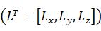
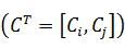
第二感測器資料(例如是圖9A中所繪示的3D-20Hz稀疏點雲(L))的映射僅在位於2D-30Hz 彩色影像(C)的FOV中的點雲上執行。並且資料校準演算法會使用轉換矩陣703的旋轉矩陣作為:
此外,基於平移矩陣以進一步替換獲取的點:
之後,根據可用的攝影機內部參數來轉換獲取的點,其中內部參數可使用影像校正來獲取:
最後,處理獲取的點以取得原始點雲資料的所需二維呈現:
此外,處理器將通過使用時間校準演算法來校準第一分割結果的時間參數(即,圖8B中所繪示的基於顏色的分割圖(Sc
))與校準後第二感測器資料的時間參數(即,圖9A中所繪示的2D-20Hz稀疏點雲(
通常,光達傳感器陣列702會具有頻率fL(例如是20Hz)的採樣率,而彩色攝影機陣列701的採樣率則可達到頻率fC(例如是30Hz)。此條件表示需要透過同步技術來將光達傳感器陣列702的資料從20Hz上採樣到30Hz。因此,處理器將會同步第一分割結果的採樣率和校準後第二感測器資料的採樣率。Generally, the
圖9B中繪示時間校準演算法的插值技術。依據圖9B的繪示,光達傳感器陣列702每50毫秒(ms)可拍攝一個點雲體積,因此光達傳感器陣列702可以分別在時間0ms、50ms、100ms、150ms、200ms、250ms和300ms處(如圖9B所繪示)拍攝點雲體積。而彩色攝影機陣列701則可以每33ms拍攝一張影像,因此彩色攝影機陣列701可以在時間0ms、33ms、67ms、100ms、133ms、167ms、200ms、233ms、267ms和300ms處(如圖9B所示)拍攝影像。處理器可以直接同步在相同時間(即,0ms、100ms、200ms、300ms)所拍攝的影像。The interpolation technique of the time calibration algorithm is shown in FIG. 9B. According to the drawing of FIG. 9B, the
接著,處理器將對光達傳感器陣列702的前兩個資料執行插值技術。換句話說,處理器將處理光達傳感器陣列702在不同的時間點所拍攝的的資料。處理器將使用光達傳感器陣列702在時間0ms和50ms所拍攝的影像,以產生光達傳感器陣列702在時間67ms的影像。處理器然後將使用光達傳感器陣列702在時間67ms和100ms所拍攝的影像,以產生光達傳感器陣列702在時間133ms的影像,並依此類推,以產生在時間167ms的影像,在時間233ms的影像,在時間267 ms的影像。在這之後,處理器將根據自動駕駛車輛的時間差和自動駕駛車輛的動量開始對基於顏色的分割圖(Sc
)和3D-20Hz稀疏點雲(L)進行同步。Next, the processor will perform an interpolation technique on the first two data of the
如圖9C所繪示,處理器將考慮自動駕駛車輛和周圍物體的運動可能性來執行插值技術。詳細來說明,在時間校準演算法的插值技術中,處理器將識別在具有新獲取的點雲體積


其中,

在第一個分割結果(即基於顏色的分割圖(Sc
))的片段SEG中的每一對點雲中,於t-1時間的新點雲體積(即點Pt5,Pt6)被預測為:


據此,從同步後第二感測器資料的體積資料重新映射最初獲取或人工產生的所有點雲,採樣率應該已經從頻率fL(即20Hz)被同步至頻率fC(即30Hz)。According to this, from the volume data of the second sensor data after synchronization, all the point clouds acquired or artificially remapped, the sampling rate should have been synchronized from the frequency fL (ie 20 Hz) to the frequency fC (ie 30 Hz).
圖10A~圖10C示出根據本揭露的示範性實施例中的一個的遮擋修正演算法。請同步參照圖7和圖10A~圖10C,其中在通過使用第一深度估計演算法來融合第一分割結果和同步後第二感測器資料,以產生第一深度結果(即,顏色導向的深度估計步驟S722)的步驟之前,處理器更用以:通過使用遮擋修正演算法(即遮擋修正步驟S740)來處理同步後第二感測器資料,其中遮擋修正演算法包括:掃描所有片段;識別多個片段中的每個片段的多個點雲的設置,以在多個片段中的各部分片段中找到被遮擋點以及多個非被遮擋點;以多個片段中的各部分片段中的多個非被遮擋點的平均深度值,替換被遮擋點的深度值。10A-10C illustrate an occlusion correction algorithm according to one of the exemplary embodiments of the present disclosure. Please refer to FIG. 7 and FIG. 10A to FIG. 10C synchronously, in which the first segmentation result and the second sensor data are fused by using the first depth estimation algorithm to generate the first depth result (ie, color-oriented Before the step of depth estimation step S722), the processor is further used to: process the synchronized second sensor data by using an occlusion correction algorithm (ie, occlusion correction step S740), where the occlusion correction algorithm includes: scanning all segments; Identify the setting of multiple point clouds for each segment in multiple segments to find the occluded points and multiple non-occluded points in each segment of multiple segments; in each segment of multiple segments The average depth value of multiple non-occluded points replaces the depth value of the occluded point.
詳細地說,圖10A示出本揭露的示範性實施例中的一個的彩色攝影機陣列701和光達傳感器陣列702的設置位置。在本實施例中,第一類型感測器具有比第二類型感測器低的設置位置,例如,彩色攝影機陣列701的設置位置是被設置在車輛V100的引擎蓋上,而光達傳感器陣列702的設置位置則是被設置在車輛V100的車頂上。據此,光達傳感器陣列702的FOV可以大於彩色攝影機陣列701的FOV,因此,光達傳感器陣列702可以拍攝到被另一物體(例如物體OB2)所遮擋的物體(例如物體OB1)的點雲體積,其中物體OB2比物體OB1更靠近車輛V100。換句話說,由於物體OB2的遮擋,彩色攝影機陣列701無法拍攝到物體OB1的影像。遮擋修正將會修正物體OB2的深度之外的點雲,如圖10A所繪示。In detail, FIG. 10A shows an arrangement position of a
因此,處理器將被配置為通過使用遮擋修正演算法來處理同步後第二感測器資料。關於遮擋修正演算法的細節,處理器將以第一分割結果(即,圖10B中所繪示的基於顏色的分割圖(Sc
))來處理同步後第二感測器資料(即,如圖10B所繪示的2D-30Hz稀疏點雲(
詳細來說明,處理器將通過掃描視窗SW1(如圖10C所繪示)來掃描2D-30Hz稀疏點雲(
在使第二感測器資料的空間參數及時間參數,與第一分割結果的空間參數及時間參數同步之後,執行深度估計演算法。在此以兩階段的演算法來執行深度估計演算法,第一深度估計演算法(即,顏色導向的深度估計)和第二深度估計演算法(即,物體導向的深度估計)。圖11A~圖11B示出根據本揭露的示範性實施例中的一個的第一深度估計演算法。請同步參照圖7和圖11A~圖11B,在顏色導向的深度估計步驟S722中,處理器將通過使用第一深度估計演算法來融合第一分割結果和同步後第二感測器資料,以產生第一深度結果(如圖7和圖11A~圖11B所繪示)。After synchronizing the spatial and temporal parameters of the second sensor data with the spatial and temporal parameters of the first segmentation result, a depth estimation algorithm is executed. Here, a two-stage algorithm is used to execute the depth estimation algorithm, a first depth estimation algorithm (ie, color-oriented depth estimation) and a second depth estimation algorithm (ie, object-oriented depth estimation). 11A-11B illustrate a first depth estimation algorithm according to one of the exemplary embodiments of the present disclosure. Please refer to FIG. 7 and FIGS. 11A-11B synchronously. In the color-guided depth estimation step S722, the processor will fuse the first segmentation result and the synchronized second sensor data by using the first depth estimation algorithm to Generate the first depth result (as shown in Figure 7 and Figure 11A ~ Figure 11B).
詳細來說明,第一深度估計演算法包括:計算所述多個片段的各所述部分片段中的所述多個點雲的平均深度值,並以所述多個片段中各所述部分片段對應的所述平均深度值填充所述多個片段中各所述部分片段的深度值。更具體來說,處理器將計算同步後第二感測器資料(例如圖10B中所繪示的2D-30Hz稀疏點雲(
處理器然後將以所述多個片段中各所述部分片段對應的所述平均深度值填充所述多個片段中各所述部分片段(即,圖11A中所繪示的片段SEG)的深度值,以產生第一深度結果(即,圖11B中所繪示的高解析度深度圖(D))。如此一來,處理器可以通過使用第一深度估計演算法來融合第一分割結果(即,圖11B中所繪示的基於顏色的分割圖(Sc
))和同步後第二感測器資料(即,圖11B所繪示的2D-30Hz稀疏點雲(
圖12A~圖12B示出根據本揭露的示範性實施例中的一個的第二深度估計演算法。請同步參照圖7及圖12A~圖12B,在物體導向的深度估計步驟S730(如圖7及圖12A~圖12B所繪示)中,處理器將通過使用第二深度估計演算法來融合第二分割結果與第一深度結果,以產生第二深度結果。詳細來說明,第二深度估計演算法包括識別多個片段的設置以找到未定義深度值區域;掃描多個片段,以找到與未定義深度值區域相近的多個片段的最小深度值;並且以最小深度值來填充未定義區域的深度值。12A-12B illustrate a second depth estimation algorithm according to one of the exemplary embodiments of the present disclosure. Please refer to FIGS. 7 and 12A-12B synchronously. In the object-guided depth estimation step S730 (as shown in FIGS. 7 and 12A-12B), the processor will fuse the second depth estimation algorithm. The two segmentation results and the first depth result to produce a second depth result. In detail, the second depth estimation algorithm includes the setting of identifying a plurality of fragments to find an area of undefined depth values; scanning the plurality of fragments to find the minimum depth value of a plurality of fragments close to the area of undefined depth values; and The minimum depth value is used to fill the depth value of the undefined area.
具體來說明,處理器將通過掃描視窗SW2來識別多個片段的設置,以找到未定義深度值區域(例如,圖12A中所繪示的影像中的物體OBS的片段),其中物體OBS包括多個片段SEG。然後處理器將掃描多個片段(即,圖12A中所繪示的影像中與未定義深度區域UNR相近的片段)以找到未定義深度區域UNR相近的多個片段的最小深度值。處理器將以最小深度值(如圖12A所繪示)來填充未定義深度值區域UNR的深度值,以產生第二深度結果(例如,圖12B中所繪示的高解析度深度圖(D'))。Specifically, the processor will identify the settings of multiple segments by scanning the window SW2 to find areas with undefined depth values (for example, segments of the object OBS in the image shown in FIG. 12A), where the object OBS includes multiple Fragments SEG. Then the processor will scan multiple segments (ie, the segment in the image shown in FIG. 12A that is close to the undefined depth region UNR) to find the minimum depth value of the multiple segments that are close to the undefined depth region UNR. The processor will fill the depth value of the undefined depth value area UNR with the minimum depth value (as shown in FIG. 12A) to generate a second depth result (for example, the high-resolution depth map shown in FIG. 12B (D ')).
如此一來,處理器可以通過使用第二深度估計演算法來融合第二分割結果(即,圖12B中所繪示的基於物體的分割圖(So
))與第一深度結果(即,圖12B中所繪示的高解析度深度圖(D)),以產生第二深度結果(即,圖12B中所繪示的高解析度深度圖(D')),其中第二深度結果為稠密深度資料。據此,本公開藉由彩色攝影機陣列701,光達傳感器陣列702和處理器,以通過影像校正演算法,兩階段的分割演算法,資料校準演算法和兩階度的深度估計演算法來改善深度圖的解析度。In this way, the processor can fuse the second segmentation result (that is, the object-based segmentation map (S o ) shown in FIG. 12B) and the first depth result (that is, the graph) by using the second depth estimation algorithm 12B shows the high-resolution depth map (D)) to generate a second depth result (ie, the high-resolution depth map (D') shown in FIG. 12B), where the second depth result is dense In-depth information. Accordingly, the present disclosure is improved by the
圖13A~圖13C示出根據本揭露的示範性實施例中的一個的深度估計方法的另一實施實例。自動駕駛車輛V1310包括深度估計裝置1300。深度估計裝置1300包括前右光達1302a,前左光達1302b,前攝影機1301以及處理單元1303。前右光達1302a、前左光達1302b以及前攝影機1301耦接至處理單元1303,其中處理單元1303例如是具有Intel Core i7 @ 2.4GHz 4GB 隨機存取記憶體(random access memory,RAM)和NVidia GeForce 940M 2GB 視訊記憶體(video RAM,VRAM),並且在Ubuntu 16.04 LTS上運行的個人計算機。13A to 13C illustrate another implementation example of the depth estimation method according to one of the exemplary embodiments of the present disclosure. The self-driving vehicle V1310 includes a
請同步參照圖13A~圖13C,深度估計裝置1300可以準確地估計同步後第二感測器資料(即,圖13B中所繪示的具有彩色影像的2D-20Hz稀疏光達)的稠密深度值,並可估計第二深度結果的稠密深度值(即,圖13C中所繪示的2D-30Hz高解析度深度圖)。此外,上述實施例所實現的平均複雜度可達到每秒26.232畫面(frame per second,FPS)(或每畫面38.122ms)。通過對顏色導向和物體導向的估計(例如是邊界框區域)來應用有限的計算區域,可以簡單地減少深度估計裝置1300的複雜度。換句話說,處理單元1303將被配置至少用以執行影像校正演算法以產生校正後第一感測器資料,執行兩階段的分割演算法以產生第一分割結果和第二分割結果,執行資料校準演算法以產生同步後第二感測器資料,並執行兩階段的深度估計演算法以產生第一深度結果(即,圖13B中所繪示的具有彩色影像的2D-20Hz稀疏光達)和第二深度結果(即,圖13C中所繪示的2D-30Hz高解析度深度圖)。Please refer to FIGS. 13A to 13C synchronously. The
需要注意的是,深度估計裝置1300與圖2、圖5或圖7實施例中所繪示的深度估計裝置相同或相類似,在此不重複贅述。It should be noted that the
圖14A~圖14E示出根據本揭露的示範性實施例中的一個的深度估計方法的另一實施實例。自動駕駛車輛V1410包括深度估計裝置1400。深度估計裝置1400包括第一類型感測器(例如,立體攝影機1401)、第二類型感測器(例如,威力登雷射掃描器1402)、全球定位系統(Global Positioning System,GPS)1404和處理器1403。威力登雷射掃描器1402、立體攝像機1401以及GPS 1404耦接至處理器1403,其中處理器1403例如是具有Intel Core i7 @ 2.4GHz 4GB 隨機存取記憶體和NVidia GeForce 940M 2GB 視訊記憶體,並且在Ubuntu 16.04 LTS上運行的個人計算機。14A to 14E show another implementation example of the depth estimation method according to one of the exemplary embodiments of the present disclosure. The self-driving vehicle V1410 includes a
由立體攝像機1401所拍攝的影像如圖14B所繪示。由威力登雷射掃描器1402所拍攝的影像如圖14C所繪示。詳細來說名,處理器1403將被配置為至少用以執行影像校正演算法以產生校正後第一感測器資料,執行兩階段的分割演算法以產生第一分割結果和第二分割結果,執行資料校準演算法以產生同步後第二感測器資料,並執行兩階段的深度估計演算法以產生第一深度結果(如圖14D所繪示)和第二深度結果,其中第二深度結果為稠密高解析度深度圖(如圖14E所示)。The image captured by the
需要注意的是,深度估計裝置1400與圖2、圖5或圖7實施例中所繪示的深度估計裝置相同或相類似,在此不重複贅述。It should be noted that the
綜上所述,本揭露提供適合用於自動駕駛車輛的深度估計裝置。具體地說,本揭露的目的可包含:通過使用所提供的兩階段的分割的來改善來自各感測器的深度圖的解析度,通過考慮影像的特性來設計所提供的兩階段的分割,並且提供基於顏色資訊和物體資訊的兩階段的深度估計。通過這種方式,可以提高深度估計的準確性。In summary, the present disclosure provides a depth estimation device suitable for autonomous vehicles. Specifically, the purpose of the present disclosure may include: improving the resolution of the depth map from each sensor by using the provided two-stage segmentation, and designing the provided two-stage segmentation by considering the characteristics of the image, It also provides two-stage depth estimation based on color information and object information. In this way, the accuracy of depth estimation can be improved.
本申請所揭露的實施例的詳細描述中使用的元件、動作或指令不應解釋為對本揭露來說絕對關鍵或必要的,除非明確地如此描述。而且,如本文中所使用,不定冠詞“一(a/an)”可以包含一個以上專案。如果意圖表示只有一個專案,那麼能夠使用術語“單個”或類似語言。此外,如本文中所使用,在多個項目和/或多個項目種類的列表之前的術語“中的任一個”意圖包含所述項目和/或項目種類個別地或結合其它項目和/或其它項目種類“中的任一個”、“中的任何組合”、“中的任何多個”和/或“中的多個的任何組合”。此外,如本文中所使用,術語“集合”意圖包含任何數目個專案,包含零個。此外,如本文中所使用,術語“數目”意圖包含任何數目,包含零。The elements, actions or instructions used in the detailed description of the embodiments disclosed in this application should not be interpreted as absolutely critical or necessary for the present disclosure unless explicitly described as such. Moreover, as used in this article, the indefinite article "a (an)" can contain more than one project. If the intention indicates that there is only one project, then the term "single" or similar language can be used. Furthermore, as used herein, the term "any of" before a list of multiple items and/or multiple item categories is intended to encompass the item and/or item category individually or in combination with other items and/or other Item category "any of", "any combination of", "any multiple of" and/or "any combination of multiple". In addition, as used herein, the term "collection" is intended to include any number of projects, including zero. Furthermore, as used herein, the term "number" is intended to include any number, including zero.
本領域的技術人員將顯而易見,在不脫離本揭露的範圍或精神的情況下,可對所揭露的實施例的結構作出各種修改和變化。鑒於前述內容,意圖本揭露涵蓋屬於隨附權利要求書和其等效物的範圍內的本揭露的修改及變化。It will be apparent to those skilled in the art that various modifications and changes can be made in the structure of the disclosed embodiments without departing from the scope or spirit of the disclosure. In view of the foregoing, it is intended that this disclosure covers modifications and changes within the scope of the appended claims and their equivalents.
雖然本發明已以實施例揭露如上,然其並非用以限定本發明,任何所屬技術領域中具有通常知識者,在不脫離本發明的精神和範圍內,當可作些許的更動與潤飾,故本發明的保護範圍當視後附的申請專利範圍所界定者為準。Although the present invention has been disclosed as above with examples, it is not intended to limit the present invention. Any person with ordinary knowledge in the technical field can make some changes and modifications without departing from the spirit and scope of the present invention. The scope of protection of the present invention shall be subject to the scope defined in the appended patent application.
200、1300、1400:深度估計裝置210:第一類型感測器220:第二類型感測器230:處理器300、V1310、V1410:自動駕駛車輛S410、S412、S420、S421、S422、S430:步驟501、701:彩色攝影機陣列502、702:光達傳感器陣列S510、S710:彩色影像資料步驟S511、S711:影像校正步驟S512a、S712a:基於顏色的分割步驟S512b、S712b:基於物體的分割步驟S520、S720:深度體積資料步驟S521:資料校準步驟S522、S722:顏色導向的深度估計步驟S530、S730:物體導向的深度估計步驟703:轉換矩陣S711a:校正後彩色影像資料步驟S721a:空間校準步驟S721b:時間校準步驟S740:遮擋修正步驟S740a:修正後深度體積資料步驟SEG:片段Pt1~Pt6、Pout:點t、t-1、t+1:時間OB1、OB2、OBS:物體V100:車輛SW1、SW2:掃描視窗P100:被遮擋點UNR:未定義深度值區域1301:前攝影機1302a:前右光達1302b:前左光達1303:處理單元1401:立體攝影機1402:威力登雷射掃描器1403:處理器1404:全球定位系統200, 1300, 1400: Depth estimation device 210: First type sensor 220: Second type sensor 230:
圖1A示出了可用於產生深度圖的各種感測器。 圖1B示出了低解析度光達資料和高解析度光達資料之間的比較。 圖2示出根據本揭露的示範性實施例中的一個的深度估計裝置的硬體方塊圖。 圖3示出根據本揭露的示範性實施例中的一個的使用深度估計裝置的自動駕駛車輛。 圖4示出是根據本揭露的示範性實施例中的一個使用深度估計裝置的深度估計方法的步驟的流程圖。 圖5示出根據本揭露的示範性實施例中的一個的深度估計架構的詳細方塊圖。 圖6A~圖6F示出根據本揭露的示範性實施例中的一個的深度估計方法的一個實施實例。 圖7示出根據本揭露的示範性實施例中的一個的深度估計架構的詳細方塊圖。 圖8A示出根據本揭露的示範性實施例中的一個的影像校正演算法。 圖8B示出根據本揭露的示範性實施例中的一個的第一分割演算法。 圖8C示出根據本揭露的示範性實施例中的一個的第二分割演算法。 圖9A~圖9C示出根據本揭露的示範性實施例中的一個的資料校準演算法。 圖10A~圖10C示出根據本揭露的示範性實施例中的一個的遮擋修正演算法。 圖11A~圖11B示出根據本揭露的示範性實施例中的一個的第一深度估計演算法。 圖12A~圖12B示出根據本揭露的示範性實施例中的一個的第二深度估計演算法。 圖13A~圖13C示出根據本揭露的示範性實施例中的一個的深度估計方法的另一實施實例。 圖14A~圖14E示出根據本揭露的示範性實施例中的一個的深度估計方法的另一實施實例。FIG. 1A shows various sensors that can be used to generate a depth map. FIG. 1B shows a comparison between low-resolution lidar data and high-resolution lidar data. FIG. 2 shows a hardware block diagram of a depth estimation device according to one of the exemplary embodiments of the present disclosure. FIG. 3 illustrates an autonomous driving vehicle using a depth estimation device according to one of the exemplary embodiments of the present disclosure. 4 is a flowchart illustrating steps of a depth estimation method using a depth estimation device according to an exemplary embodiment of the present disclosure. FIG. 5 shows a detailed block diagram of a depth estimation architecture according to one of the exemplary embodiments of the present disclosure. 6A to 6F illustrate an implementation example of a depth estimation method according to one of the exemplary embodiments of the present disclosure. 7 shows a detailed block diagram of a depth estimation architecture according to one of the exemplary embodiments of the present disclosure. FIG. 8A shows an image correction algorithm according to one of the exemplary embodiments of the present disclosure. FIG. 8B shows a first segmentation algorithm according to one of the exemplary embodiments of the present disclosure. FIG. 8C shows a second segmentation algorithm according to one of the exemplary embodiments of the present disclosure. 9A-9C illustrate a data calibration algorithm according to one of the exemplary embodiments of the present disclosure. 10A-10C illustrate an occlusion correction algorithm according to one of the exemplary embodiments of the present disclosure. 11A-11B illustrate a first depth estimation algorithm according to one of the exemplary embodiments of the present disclosure. 12A-12B illustrate a second depth estimation algorithm according to one of the exemplary embodiments of the present disclosure. 13A to 13C illustrate another implementation example of the depth estimation method according to one of the exemplary embodiments of the present disclosure. 14A to 14E show another implementation example of the depth estimation method according to one of the exemplary embodiments of the present disclosure.
S410、S412、S420、S421、S422、S430:步驟 S410, S412, S420, S421, S422, S430: steps
Claims (22)
Priority Applications (1)
| Application Number | Priority Date | Filing Date | Title |
|---|---|---|---|
| CN201910115287.5A CN111105449B (en) | 2018-10-09 | 2019-02-14 | Depth estimation device, self-driving vehicle and depth estimation method thereof |
Applications Claiming Priority (2)
| Application Number | Priority Date | Filing Date | Title |
|---|---|---|---|
| US16/154,738 | 2018-10-09 | ||
| US16/154,738 US10699430B2 (en) | 2018-10-09 | 2018-10-09 | Depth estimation apparatus, autonomous vehicle using the same, and depth estimation method thereof |
Publications (2)
| Publication Number | Publication Date |
|---|---|
| TW202014990A true TW202014990A (en) | 2020-04-16 |
| TWI709943B TWI709943B (en) | 2020-11-11 |
Family
ID=70052214
Family Applications (1)
| Application Number | Title | Priority Date | Filing Date |
|---|---|---|---|
| TW107142123A TWI709943B (en) | 2018-10-09 | 2018-11-26 | Depth estimation apparatus, autonomous vehicle using the same, and depth estimation method thereof |
Country Status (3)
| Country | Link |
|---|---|
| US (1) | US10699430B2 (en) |
| JP (1) | JP6744900B2 (en) |
| TW (1) | TWI709943B (en) |
Cited By (1)
| Publication number | Priority date | Publication date | Assignee | Title |
|---|---|---|---|---|
| TWI830363B (en) * | 2022-05-19 | 2024-01-21 | 鈺立微電子股份有限公司 | Sensing device for providing three dimensional information |
Families Citing this family (15)
| Publication number | Priority date | Publication date | Assignee | Title |
|---|---|---|---|---|
| US11244464B2 (en) * | 2018-03-09 | 2022-02-08 | Samsung Electronics Co., Ltd | Method and apparatus for performing depth estimation of object |
| US20200137380A1 (en) * | 2018-10-31 | 2020-04-30 | Intel Corporation | Multi-plane display image synthesis mechanism |
| US11507789B2 (en) * | 2019-05-31 | 2022-11-22 | Lg Electronics Inc. | Electronic device for vehicle and method of operating electronic device for vehicle |
| US11151798B1 (en) * | 2019-11-13 | 2021-10-19 | Apple Inc. | Depth rate up-conversion |
| CN111860425B (en) * | 2020-07-30 | 2021-04-09 | 清华大学 | Deep multi-mode cross-layer cross fusion method, terminal device and storage medium |
| TWI812888B (en) * | 2020-10-14 | 2023-08-21 | 財團法人工業技術研究院 | Image recognition method and image recognition system |
| TWI802827B (en) * | 2020-12-01 | 2023-05-21 | 財團法人國家實驗研究院 | Method for correcting abnormal point cloud |
| CN112632201B (en) * | 2020-12-12 | 2022-05-13 | 武汉中海庭数据技术有限公司 | Traffic road topology network construction method and device |
| CN112686204B (en) * | 2021-01-12 | 2022-09-02 | 昆明理工大学 | Video flow measurement method and device based on sparse pixel point tracking |
| US11909950B1 (en) * | 2021-09-21 | 2024-02-20 | Amazon Technologies, Inc. | Three-dimensional (3D) sensor performance evaluation |
| WO2023162497A1 (en) * | 2022-02-22 | 2023-08-31 | ソニーセミコンダクタソリューションズ株式会社 | Image-processing device, image-processing method, and image-processing program |
| KR20240111593A (en) | 2023-01-10 | 2024-07-17 | 현대자동차주식회사 | Apparatus for generating depth map of monocular camera image and method thereof |
| US20240291993A1 (en) * | 2023-02-28 | 2024-08-29 | Ford Global Technologies, Llc | Rule-based digitized image compression |
| WO2024190436A1 (en) * | 2023-03-16 | 2024-09-19 | ソニーグループ株式会社 | Information processing device, information processing method, and program |
| KR20250119134A (en) * | 2024-01-31 | 2025-08-07 | 에스케이하이닉스 주식회사 | Image processor and image processing system including the image processor |
Family Cites Families (18)
| Publication number | Priority date | Publication date | Assignee | Title |
|---|---|---|---|---|
| TWI225222B (en) | 2003-10-22 | 2004-12-11 | Leadtek Research Inc | Robust face detection algorithm for real-time video sequence |
| EP2184713A1 (en) | 2008-11-04 | 2010-05-12 | Koninklijke Philips Electronics N.V. | Method and device for generating a depth map |
| CN102043510A (en) | 2009-10-09 | 2011-05-04 | 禾瑞亚科技股份有限公司 | Method and device for analyzing two-dimensional sensing information |
| WO2012056686A1 (en) | 2010-10-27 | 2012-05-03 | パナソニック株式会社 | 3d image interpolation device, 3d imaging device, and 3d image interpolation method |
| US20130095920A1 (en) | 2011-10-13 | 2013-04-18 | Microsoft Corporation | Generating free viewpoint video using stereo imaging |
| US9514522B2 (en) * | 2012-08-24 | 2016-12-06 | Microsoft Technology Licensing, Llc | Depth data processing and compression |
| TWI579797B (en) | 2012-08-31 | 2017-04-21 | 禾瑞亞科技股份有限公司 | Processor for image segmentation |
| JP5818773B2 (en) | 2012-11-22 | 2015-11-18 | キヤノン株式会社 | Image processing apparatus, image processing method, and program |
| CN104346608B (en) | 2013-07-26 | 2017-09-08 | 株式会社理光 | Sparse depth figure denseization method and apparatus |
| US9275078B2 (en) * | 2013-09-05 | 2016-03-01 | Ebay Inc. | Estimating depth from a single image |
| US9778363B2 (en) | 2013-10-24 | 2017-10-03 | Massachusetts Institute Of Technology | Methods and apparatus for coded time-of-flight camera |
| JP6351238B2 (en) | 2013-11-15 | 2018-07-04 | キヤノン株式会社 | Image processing apparatus, imaging apparatus, and distance correction method |
| US20150381972A1 (en) | 2014-06-30 | 2015-12-31 | Microsoft Corporation | Depth estimation using multi-view stereo and a calibrated projector |
| WO2017014691A1 (en) | 2015-07-17 | 2017-01-26 | Heptagon Micro Optics Pte. Ltd. | Generating a distance map based on captured images of a scene |
| US10282591B2 (en) | 2015-08-24 | 2019-05-07 | Qualcomm Incorporated | Systems and methods for depth map sampling |
| CN106162147B (en) | 2016-07-28 | 2018-10-16 | 天津大学 | Depth recovery method based on binocular Kinect depth camera systems |
| US9972067B2 (en) | 2016-10-11 | 2018-05-15 | The Boeing Company | System and method for upsampling of sparse point cloud for 3D registration |
| CN107767357B (en) | 2017-09-14 | 2021-04-09 | 北京工业大学 | A Deep Image Super-Resolution Method Based on Multi-Orientation Dictionary |
-
2018
- 2018-10-09 US US16/154,738 patent/US10699430B2/en active Active
- 2018-11-26 TW TW107142123A patent/TWI709943B/en active
- 2018-11-26 JP JP2018220031A patent/JP6744900B2/en active Active
Cited By (1)
| Publication number | Priority date | Publication date | Assignee | Title |
|---|---|---|---|---|
| TWI830363B (en) * | 2022-05-19 | 2024-01-21 | 鈺立微電子股份有限公司 | Sensing device for providing three dimensional information |
Also Published As
| Publication number | Publication date |
|---|---|
| JP6744900B2 (en) | 2020-08-19 |
| TWI709943B (en) | 2020-11-11 |
| US20200111225A1 (en) | 2020-04-09 |
| JP2020061114A (en) | 2020-04-16 |
| US10699430B2 (en) | 2020-06-30 |
Similar Documents
| Publication | Publication Date | Title |
|---|---|---|
| TWI709943B (en) | Depth estimation apparatus, autonomous vehicle using the same, and depth estimation method thereof | |
| CN112346073B (en) | A data fusion method of dynamic vision sensor and laser radar | |
| EP3614171B1 (en) | Image processing method, computer-readable storage medium, and electronic apparatus | |
| CN110799918B (en) | Method, device and computer readable storage medium for vehicle, vehicle | |
| KR102151815B1 (en) | Method and Apparatus for Vehicle Detection Using Lidar Sensor and Camera Convergence | |
| US10839539B2 (en) | System and method for active stereo depth sensing | |
| US9165190B2 (en) | 3D human pose and shape modeling | |
| Gandhi et al. | High-resolution depth maps based on TOF-stereo fusion | |
| US8787656B2 (en) | Method and apparatus for feature-based stereo matching | |
| JP2004530144A (en) | How to provide image information | |
| WO2016199244A1 (en) | Object recognition device and object recognition system | |
| Martel et al. | An active approach to solving the stereo matching problem using event-based sensors | |
| WO2020087485A1 (en) | Method for acquiring depth image, device for acquiring depth image, and electronic device | |
| WO2022195954A1 (en) | Sensing system | |
| EP4509878A1 (en) | Laser radar point cloud processing method and apparatus | |
| GB2562037A (en) | Three-dimensional scene reconstruction | |
| TW202347258A (en) | Depth processing system and operational method thereof | |
| CN119379816A (en) | Camera calibration method, device and storage medium based on radar matching | |
| CN109242900A (en) | Locating focal plane method, processing unit, locating focal plane system and storage medium | |
| KR20230109406A (en) | Apparatus and method for detecting an object based on fusion of thermal imaging camera and lidar sensor | |
| WO2023095375A1 (en) | Three-dimensional model generation method and three-dimensional model generation device | |
| CN115588042A (en) | Motion detection method, device and equipment based on event camera and lidar | |
| JP2001208522A (en) | Range image generating apparatus, range image generating method, and program providing medium | |
| CN111105449B (en) | Depth estimation device, self-driving vehicle and depth estimation method thereof | |
| CN110785788B (en) | Systems and methods for active stereo depth sensing |