TW202128553A - Metal nitride production method - Google Patents
Metal nitride production method Download PDFInfo
- Publication number
- TW202128553A TW202128553A TW109142732A TW109142732A TW202128553A TW 202128553 A TW202128553 A TW 202128553A TW 109142732 A TW109142732 A TW 109142732A TW 109142732 A TW109142732 A TW 109142732A TW 202128553 A TW202128553 A TW 202128553A
- Authority
- TW
- Taiwan
- Prior art keywords
- powder
- metal
- raw material
- molded body
- silicon nitride
- Prior art date
Links
- 229910052751 metal Inorganic materials 0.000 title claims abstract description 141
- 239000002184 metal Substances 0.000 title claims abstract description 141
- 150000004767 nitrides Chemical class 0.000 title claims abstract description 95
- 238000004519 manufacturing process Methods 0.000 title claims abstract description 33
- 239000000843 powder Substances 0.000 claims abstract description 227
- 238000006243 chemical reaction Methods 0.000 claims abstract description 109
- 238000002485 combustion reaction Methods 0.000 claims abstract description 22
- 238000005121 nitriding Methods 0.000 claims abstract description 15
- 239000002994 raw material Substances 0.000 claims description 95
- IJGRMHOSHXDMSA-UHFFFAOYSA-N Atomic nitrogen Chemical compound N#N IJGRMHOSHXDMSA-UHFFFAOYSA-N 0.000 claims description 60
- 238000000034 method Methods 0.000 claims description 53
- 229910052757 nitrogen Inorganic materials 0.000 claims description 29
- 229910052710 silicon Inorganic materials 0.000 claims description 20
- 239000010703 silicon Substances 0.000 claims description 19
- 239000000463 material Substances 0.000 claims description 9
- 230000035699 permeability Effects 0.000 claims description 6
- 238000012546 transfer Methods 0.000 claims description 4
- 230000002194 synthesizing effect Effects 0.000 claims description 3
- 239000000853 adhesive Substances 0.000 claims description 2
- 230000001070 adhesive effect Effects 0.000 claims description 2
- 239000012299 nitrogen atmosphere Substances 0.000 abstract description 5
- 239000007858 starting material Substances 0.000 abstract description 5
- 239000011800 void material Substances 0.000 abstract description 2
- 229910052581 Si3N4 Inorganic materials 0.000 description 96
- HQVNEWCFYHHQES-UHFFFAOYSA-N silicon nitride Chemical compound N12[Si]34N5[Si]62N3[Si]51N64 HQVNEWCFYHHQES-UHFFFAOYSA-N 0.000 description 96
- XUIMIQQOPSSXEZ-UHFFFAOYSA-N Silicon Chemical compound [Si] XUIMIQQOPSSXEZ-UHFFFAOYSA-N 0.000 description 42
- 238000010298 pulverizing process Methods 0.000 description 38
- 239000002245 particle Substances 0.000 description 37
- 238000005049 combustion synthesis Methods 0.000 description 24
- 239000011863 silicon-based powder Substances 0.000 description 24
- 238000005245 sintering Methods 0.000 description 16
- 239000000428 dust Substances 0.000 description 14
- 239000003085 diluting agent Substances 0.000 description 13
- 238000009826 distribution Methods 0.000 description 11
- 238000000465 moulding Methods 0.000 description 11
- 238000011084 recovery Methods 0.000 description 11
- 238000010304 firing Methods 0.000 description 9
- 238000005259 measurement Methods 0.000 description 9
- 239000000126 substance Substances 0.000 description 8
- ZOXJGFHDIHLPTG-UHFFFAOYSA-N Boron Chemical compound [B] ZOXJGFHDIHLPTG-UHFFFAOYSA-N 0.000 description 7
- LFQSCWFLJHTTHZ-UHFFFAOYSA-N Ethanol Chemical compound CCO LFQSCWFLJHTTHZ-UHFFFAOYSA-N 0.000 description 7
- 230000000052 comparative effect Effects 0.000 description 7
- CPLXHLVBOLITMK-UHFFFAOYSA-N magnesium oxide Inorganic materials [Mg]=O CPLXHLVBOLITMK-UHFFFAOYSA-N 0.000 description 7
- 238000012360 testing method Methods 0.000 description 7
- XLYOFNOQVPJJNP-UHFFFAOYSA-N water Substances O XLYOFNOQVPJJNP-UHFFFAOYSA-N 0.000 description 7
- OKTJSMMVPCPJKN-UHFFFAOYSA-N Carbon Chemical compound [C] OKTJSMMVPCPJKN-UHFFFAOYSA-N 0.000 description 6
- QVGXLLKOCUKJST-UHFFFAOYSA-N atomic oxygen Chemical compound [O] QVGXLLKOCUKJST-UHFFFAOYSA-N 0.000 description 6
- 238000009694 cold isostatic pressing Methods 0.000 description 6
- 238000010586 diagram Methods 0.000 description 6
- 238000010438 heat treatment Methods 0.000 description 6
- 239000012535 impurity Substances 0.000 description 6
- XEEYBQQBJWHFJM-UHFFFAOYSA-N iron Substances [Fe] XEEYBQQBJWHFJM-UHFFFAOYSA-N 0.000 description 6
- 229910052760 oxygen Inorganic materials 0.000 description 6
- 239000001301 oxygen Substances 0.000 description 6
- 238000013001 point bending Methods 0.000 description 6
- 239000003795 chemical substances by application Substances 0.000 description 5
- 239000000395 magnesium oxide Substances 0.000 description 5
- SIWVEOZUMHYXCS-UHFFFAOYSA-N oxo(oxoyttriooxy)yttrium Chemical compound O=[Y]O[Y]=O SIWVEOZUMHYXCS-UHFFFAOYSA-N 0.000 description 5
- 229910052582 BN Inorganic materials 0.000 description 4
- PZNSFCLAULLKQX-UHFFFAOYSA-N Boron nitride Chemical compound N#B PZNSFCLAULLKQX-UHFFFAOYSA-N 0.000 description 4
- KRHYYFGTRYWZRS-UHFFFAOYSA-N Fluorane Chemical compound F KRHYYFGTRYWZRS-UHFFFAOYSA-N 0.000 description 4
- XAGFODPZIPBFFR-UHFFFAOYSA-N aluminium Chemical compound [Al] XAGFODPZIPBFFR-UHFFFAOYSA-N 0.000 description 4
- 230000015572 biosynthetic process Effects 0.000 description 4
- 238000000354 decomposition reaction Methods 0.000 description 4
- 229910001873 dinitrogen Inorganic materials 0.000 description 4
- 229910001385 heavy metal Inorganic materials 0.000 description 4
- GRYLNZFGIOXLOG-UHFFFAOYSA-N Nitric acid Chemical compound O[N+]([O-])=O GRYLNZFGIOXLOG-UHFFFAOYSA-N 0.000 description 3
- 229910052782 aluminium Inorganic materials 0.000 description 3
- 239000011324 bead Substances 0.000 description 3
- 229910052796 boron Inorganic materials 0.000 description 3
- 230000001680 brushing effect Effects 0.000 description 3
- 229910052799 carbon Inorganic materials 0.000 description 3
- 239000000919 ceramic Substances 0.000 description 3
- 238000005336 cracking Methods 0.000 description 3
- 230000007423 decrease Effects 0.000 description 3
- 239000006185 dispersion Substances 0.000 description 3
- 229910002804 graphite Inorganic materials 0.000 description 3
- 239000010439 graphite Substances 0.000 description 3
- 229910052742 iron Inorganic materials 0.000 description 3
- 239000007788 liquid Substances 0.000 description 3
- AXZKOIWUVFPNLO-UHFFFAOYSA-N magnesium;oxygen(2-) Chemical compound [O-2].[Mg+2] AXZKOIWUVFPNLO-UHFFFAOYSA-N 0.000 description 3
- 238000002844 melting Methods 0.000 description 3
- 230000008018 melting Effects 0.000 description 3
- 239000000203 mixture Substances 0.000 description 3
- 229910017604 nitric acid Inorganic materials 0.000 description 3
- 239000011347 resin Substances 0.000 description 3
- 229920005989 resin Polymers 0.000 description 3
- 238000005201 scrubbing Methods 0.000 description 3
- 239000000758 substrate Substances 0.000 description 3
- 238000003786 synthesis reaction Methods 0.000 description 3
- NLXLAEXVIDQMFP-UHFFFAOYSA-N Ammonia chloride Chemical compound [NH4+].[Cl-] NLXLAEXVIDQMFP-UHFFFAOYSA-N 0.000 description 2
- KFZMGEQAYNKOFK-UHFFFAOYSA-N Isopropanol Chemical compound CC(C)O KFZMGEQAYNKOFK-UHFFFAOYSA-N 0.000 description 2
- FAPWRFPIFSIZLT-UHFFFAOYSA-M Sodium chloride Chemical compound [Na+].[Cl-] FAPWRFPIFSIZLT-UHFFFAOYSA-M 0.000 description 2
- MCMNRKCIXSYSNV-UHFFFAOYSA-N Zirconium dioxide Chemical compound O=[Zr]=O MCMNRKCIXSYSNV-UHFFFAOYSA-N 0.000 description 2
- 238000010306 acid treatment Methods 0.000 description 2
- PNEYBMLMFCGWSK-UHFFFAOYSA-N aluminium oxide Inorganic materials [O-2].[O-2].[O-2].[Al+3].[Al+3] PNEYBMLMFCGWSK-UHFFFAOYSA-N 0.000 description 2
- 230000005540 biological transmission Effects 0.000 description 2
- 238000009841 combustion method Methods 0.000 description 2
- 238000011109 contamination Methods 0.000 description 2
- 238000007796 conventional method Methods 0.000 description 2
- PMHQVHHXPFUNSP-UHFFFAOYSA-M copper(1+);methylsulfanylmethane;bromide Chemical compound Br[Cu].CSC PMHQVHHXPFUNSP-UHFFFAOYSA-M 0.000 description 2
- 230000001186 cumulative effect Effects 0.000 description 2
- 230000006866 deterioration Effects 0.000 description 2
- 238000009792 diffusion process Methods 0.000 description 2
- 230000000694 effects Effects 0.000 description 2
- 238000002474 experimental method Methods 0.000 description 2
- 238000011049 filling Methods 0.000 description 2
- 239000010419 fine particle Substances 0.000 description 2
- 239000007789 gas Substances 0.000 description 2
- 230000017525 heat dissipation Effects 0.000 description 2
- 230000002209 hydrophobic effect Effects 0.000 description 2
- 238000009413 insulation Methods 0.000 description 2
- 230000001678 irradiating effect Effects 0.000 description 2
- 150000001247 metal acetylides Chemical class 0.000 description 2
- 150000002739 metals Chemical class 0.000 description 2
- QJGQUHMNIGDVPM-UHFFFAOYSA-N nitrogen group Chemical group [N] QJGQUHMNIGDVPM-UHFFFAOYSA-N 0.000 description 2
- 230000000704 physical effect Effects 0.000 description 2
- 229910021420 polycrystalline silicon Inorganic materials 0.000 description 2
- 238000012552 review Methods 0.000 description 2
- 239000002904 solvent Substances 0.000 description 2
- 238000003466 welding Methods 0.000 description 2
- JOYRKODLDBILNP-UHFFFAOYSA-N Ethyl urethane Chemical compound CCOC(N)=O JOYRKODLDBILNP-UHFFFAOYSA-N 0.000 description 1
- 238000002441 X-ray diffraction Methods 0.000 description 1
- 239000002253 acid Substances 0.000 description 1
- 239000000654 additive Substances 0.000 description 1
- 235000019270 ammonium chloride Nutrition 0.000 description 1
- 238000005452 bending Methods 0.000 description 1
- 244000309464 bull Species 0.000 description 1
- BRPQOXSCLDDYGP-UHFFFAOYSA-N calcium oxide Chemical compound [O-2].[Ca+2] BRPQOXSCLDDYGP-UHFFFAOYSA-N 0.000 description 1
- 239000000292 calcium oxide Substances 0.000 description 1
- ODINCKMPIJJUCX-UHFFFAOYSA-N calcium oxide Inorganic materials [Ca]=O ODINCKMPIJJUCX-UHFFFAOYSA-N 0.000 description 1
- 150000003841 chloride salts Chemical class 0.000 description 1
- 239000011362 coarse particle Substances 0.000 description 1
- 150000001875 compounds Chemical class 0.000 description 1
- 238000007906 compression Methods 0.000 description 1
- 230000006835 compression Effects 0.000 description 1
- 238000000748 compression moulding Methods 0.000 description 1
- 230000001419 dependent effect Effects 0.000 description 1
- 238000010891 electric arc Methods 0.000 description 1
- 238000005485 electric heating Methods 0.000 description 1
- 238000010292 electrical insulation Methods 0.000 description 1
- 238000004993 emission spectroscopy Methods 0.000 description 1
- 230000007613 environmental effect Effects 0.000 description 1
- 239000003344 environmental pollutant Substances 0.000 description 1
- 238000001704 evaporation Methods 0.000 description 1
- 230000008020 evaporation Effects 0.000 description 1
- 239000000835 fiber Substances 0.000 description 1
- -1 for example Substances 0.000 description 1
- 238000005469 granulation Methods 0.000 description 1
- 230000003179 granulation Effects 0.000 description 1
- 230000020169 heat generation Effects 0.000 description 1
- 238000010348 incorporation Methods 0.000 description 1
- 238000009616 inductively coupled plasma Methods 0.000 description 1
- 239000012770 industrial material Substances 0.000 description 1
- 239000004615 ingredient Substances 0.000 description 1
- 238000010299 mechanically pulverizing process Methods 0.000 description 1
- 238000002156 mixing Methods 0.000 description 1
- 229910052750 molybdenum Inorganic materials 0.000 description 1
- 229910052755 nonmetal Inorganic materials 0.000 description 1
- 239000005416 organic matter Substances 0.000 description 1
- 230000003647 oxidation Effects 0.000 description 1
- 238000007254 oxidation reaction Methods 0.000 description 1
- 230000001590 oxidative effect Effects 0.000 description 1
- TWNQGVIAIRXVLR-UHFFFAOYSA-N oxo(oxoalumanyloxy)alumane Chemical compound O=[Al]O[Al]=O TWNQGVIAIRXVLR-UHFFFAOYSA-N 0.000 description 1
- 231100000719 pollutant Toxicity 0.000 description 1
- 229920005591 polysilicon Polymers 0.000 description 1
- 238000000634 powder X-ray diffraction Methods 0.000 description 1
- 238000002360 preparation method Methods 0.000 description 1
- 238000003825 pressing Methods 0.000 description 1
- 238000002203 pretreatment Methods 0.000 description 1
- 238000000746 purification Methods 0.000 description 1
- 238000000790 scattering method Methods 0.000 description 1
- 239000004065 semiconductor Substances 0.000 description 1
- 238000007873 sieving Methods 0.000 description 1
- 239000011780 sodium chloride Substances 0.000 description 1
- FQENQNTWSFEDLI-UHFFFAOYSA-J sodium diphosphate Chemical compound [Na+].[Na+].[Na+].[Na+].[O-]P([O-])(=O)OP([O-])([O-])=O FQENQNTWSFEDLI-UHFFFAOYSA-J 0.000 description 1
- 229940048086 sodium pyrophosphate Drugs 0.000 description 1
- 238000001179 sorption measurement Methods 0.000 description 1
- 238000003756 stirring Methods 0.000 description 1
- 238000003860 storage Methods 0.000 description 1
- 238000006557 surface reaction Methods 0.000 description 1
- 235000019818 tetrasodium diphosphate Nutrition 0.000 description 1
- 239000001577 tetrasodium phosphonato phosphate Substances 0.000 description 1
- 229910052721 tungsten Inorganic materials 0.000 description 1
- 238000003826 uniaxial pressing Methods 0.000 description 1
- 230000000007 visual effect Effects 0.000 description 1
- 239000002699 waste material Substances 0.000 description 1
Images


Classifications
-
- C—CHEMISTRY; METALLURGY
- C01—INORGANIC CHEMISTRY
- C01B—NON-METALLIC ELEMENTS; COMPOUNDS THEREOF; METALLOIDS OR COMPOUNDS THEREOF NOT COVERED BY SUBCLASS C01C
- C01B21/00—Nitrogen; Compounds thereof
- C01B21/06—Binary compounds of nitrogen with metals, with silicon, or with boron, or with carbon, i.e. nitrides; Compounds of nitrogen with more than one metal, silicon or boron
- C01B21/068—Binary compounds of nitrogen with metals, with silicon, or with boron, or with carbon, i.e. nitrides; Compounds of nitrogen with more than one metal, silicon or boron with silicon
- C01B21/0682—Preparation by direct nitridation of silicon
-
- C—CHEMISTRY; METALLURGY
- C01—INORGANIC CHEMISTRY
- C01B—NON-METALLIC ELEMENTS; COMPOUNDS THEREOF; METALLOIDS OR COMPOUNDS THEREOF NOT COVERED BY SUBCLASS C01C
- C01B21/00—Nitrogen; Compounds thereof
- C01B21/06—Binary compounds of nitrogen with metals, with silicon, or with boron, or with carbon, i.e. nitrides; Compounds of nitrogen with more than one metal, silicon or boron
-
- C—CHEMISTRY; METALLURGY
- C01—INORGANIC CHEMISTRY
- C01B—NON-METALLIC ELEMENTS; COMPOUNDS THEREOF; METALLOIDS OR COMPOUNDS THEREOF NOT COVERED BY SUBCLASS C01C
- C01B21/00—Nitrogen; Compounds thereof
- C01B21/06—Binary compounds of nitrogen with metals, with silicon, or with boron, or with carbon, i.e. nitrides; Compounds of nitrogen with more than one metal, silicon or boron
- C01B21/064—Binary compounds of nitrogen with metals, with silicon, or with boron, or with carbon, i.e. nitrides; Compounds of nitrogen with more than one metal, silicon or boron with boron
-
- C—CHEMISTRY; METALLURGY
- C01—INORGANIC CHEMISTRY
- C01B—NON-METALLIC ELEMENTS; COMPOUNDS THEREOF; METALLOIDS OR COMPOUNDS THEREOF NOT COVERED BY SUBCLASS C01C
- C01B21/00—Nitrogen; Compounds thereof
- C01B21/06—Binary compounds of nitrogen with metals, with silicon, or with boron, or with carbon, i.e. nitrides; Compounds of nitrogen with more than one metal, silicon or boron
- C01B21/068—Binary compounds of nitrogen with metals, with silicon, or with boron, or with carbon, i.e. nitrides; Compounds of nitrogen with more than one metal, silicon or boron with silicon
-
- C—CHEMISTRY; METALLURGY
- C01—INORGANIC CHEMISTRY
- C01B—NON-METALLIC ELEMENTS; COMPOUNDS THEREOF; METALLOIDS OR COMPOUNDS THEREOF NOT COVERED BY SUBCLASS C01C
- C01B21/00—Nitrogen; Compounds thereof
- C01B21/06—Binary compounds of nitrogen with metals, with silicon, or with boron, or with carbon, i.e. nitrides; Compounds of nitrogen with more than one metal, silicon or boron
- C01B21/072—Binary compounds of nitrogen with metals, with silicon, or with boron, or with carbon, i.e. nitrides; Compounds of nitrogen with more than one metal, silicon or boron with aluminium
-
- C—CHEMISTRY; METALLURGY
- C04—CEMENTS; CONCRETE; ARTIFICIAL STONE; CERAMICS; REFRACTORIES
- C04B—LIME, MAGNESIA; SLAG; CEMENTS; COMPOSITIONS THEREOF, e.g. MORTARS, CONCRETE OR LIKE BUILDING MATERIALS; ARTIFICIAL STONE; CERAMICS; REFRACTORIES; TREATMENT OF NATURAL STONE
- C04B35/00—Shaped ceramic products characterised by their composition; Ceramics compositions; Processing powders of inorganic compounds preparatory to the manufacturing of ceramic products
- C04B35/515—Shaped ceramic products characterised by their composition; Ceramics compositions; Processing powders of inorganic compounds preparatory to the manufacturing of ceramic products based on non-oxide ceramics
- C04B35/58—Shaped ceramic products characterised by their composition; Ceramics compositions; Processing powders of inorganic compounds preparatory to the manufacturing of ceramic products based on non-oxide ceramics based on borides, nitrides, i.e. nitrides, oxynitrides, carbonitrides or oxycarbonitrides or silicides
- C04B35/584—Shaped ceramic products characterised by their composition; Ceramics compositions; Processing powders of inorganic compounds preparatory to the manufacturing of ceramic products based on non-oxide ceramics based on borides, nitrides, i.e. nitrides, oxynitrides, carbonitrides or oxycarbonitrides or silicides based on silicon nitride
- C04B35/591—Shaped ceramic products characterised by their composition; Ceramics compositions; Processing powders of inorganic compounds preparatory to the manufacturing of ceramic products based on non-oxide ceramics based on borides, nitrides, i.e. nitrides, oxynitrides, carbonitrides or oxycarbonitrides or silicides based on silicon nitride obtained by reaction sintering
-
- C—CHEMISTRY; METALLURGY
- C04—CEMENTS; CONCRETE; ARTIFICIAL STONE; CERAMICS; REFRACTORIES
- C04B—LIME, MAGNESIA; SLAG; CEMENTS; COMPOSITIONS THEREOF, e.g. MORTARS, CONCRETE OR LIKE BUILDING MATERIALS; ARTIFICIAL STONE; CERAMICS; REFRACTORIES; TREATMENT OF NATURAL STONE
- C04B35/00—Shaped ceramic products characterised by their composition; Ceramics compositions; Processing powders of inorganic compounds preparatory to the manufacturing of ceramic products
- C04B35/515—Shaped ceramic products characterised by their composition; Ceramics compositions; Processing powders of inorganic compounds preparatory to the manufacturing of ceramic products based on non-oxide ceramics
- C04B35/58—Shaped ceramic products characterised by their composition; Ceramics compositions; Processing powders of inorganic compounds preparatory to the manufacturing of ceramic products based on non-oxide ceramics based on borides, nitrides, i.e. nitrides, oxynitrides, carbonitrides or oxycarbonitrides or silicides
- C04B35/584—Shaped ceramic products characterised by their composition; Ceramics compositions; Processing powders of inorganic compounds preparatory to the manufacturing of ceramic products based on non-oxide ceramics based on borides, nitrides, i.e. nitrides, oxynitrides, carbonitrides or oxycarbonitrides or silicides based on silicon nitride
- C04B35/593—Shaped ceramic products characterised by their composition; Ceramics compositions; Processing powders of inorganic compounds preparatory to the manufacturing of ceramic products based on non-oxide ceramics based on borides, nitrides, i.e. nitrides, oxynitrides, carbonitrides or oxycarbonitrides or silicides based on silicon nitride obtained by pressure sintering
-
- C—CHEMISTRY; METALLURGY
- C04—CEMENTS; CONCRETE; ARTIFICIAL STONE; CERAMICS; REFRACTORIES
- C04B—LIME, MAGNESIA; SLAG; CEMENTS; COMPOSITIONS THEREOF, e.g. MORTARS, CONCRETE OR LIKE BUILDING MATERIALS; ARTIFICIAL STONE; CERAMICS; REFRACTORIES; TREATMENT OF NATURAL STONE
- C04B35/00—Shaped ceramic products characterised by their composition; Ceramics compositions; Processing powders of inorganic compounds preparatory to the manufacturing of ceramic products
- C04B35/622—Forming processes; Processing powders of inorganic compounds preparatory to the manufacturing of ceramic products
- C04B35/626—Preparing or treating the powders individually or as batches ; preparing or treating macroscopic reinforcing agents for ceramic products, e.g. fibres; mechanical aspects section B
- C04B35/62605—Treating the starting powders individually or as mixtures
- C04B35/62645—Thermal treatment of powders or mixtures thereof other than sintering
- C04B35/62675—Thermal treatment of powders or mixtures thereof other than sintering characterised by the treatment temperature
-
- C—CHEMISTRY; METALLURGY
- C04—CEMENTS; CONCRETE; ARTIFICIAL STONE; CERAMICS; REFRACTORIES
- C04B—LIME, MAGNESIA; SLAG; CEMENTS; COMPOSITIONS THEREOF, e.g. MORTARS, CONCRETE OR LIKE BUILDING MATERIALS; ARTIFICIAL STONE; CERAMICS; REFRACTORIES; TREATMENT OF NATURAL STONE
- C04B2235/00—Aspects relating to ceramic starting mixtures or sintered ceramic products
- C04B2235/02—Composition of constituents of the starting material or of secondary phases of the final product
- C04B2235/30—Constituents and secondary phases not being of a fibrous nature
- C04B2235/32—Metal oxides, mixed metal oxides, or oxide-forming salts thereof, e.g. carbonates, nitrates, (oxy)hydroxides, chlorides
- C04B2235/3205—Alkaline earth oxides or oxide forming salts thereof, e.g. beryllium oxide
- C04B2235/3206—Magnesium oxides or oxide-forming salts thereof
-
- C—CHEMISTRY; METALLURGY
- C04—CEMENTS; CONCRETE; ARTIFICIAL STONE; CERAMICS; REFRACTORIES
- C04B—LIME, MAGNESIA; SLAG; CEMENTS; COMPOSITIONS THEREOF, e.g. MORTARS, CONCRETE OR LIKE BUILDING MATERIALS; ARTIFICIAL STONE; CERAMICS; REFRACTORIES; TREATMENT OF NATURAL STONE
- C04B2235/00—Aspects relating to ceramic starting mixtures or sintered ceramic products
- C04B2235/02—Composition of constituents of the starting material or of secondary phases of the final product
- C04B2235/30—Constituents and secondary phases not being of a fibrous nature
- C04B2235/32—Metal oxides, mixed metal oxides, or oxide-forming salts thereof, e.g. carbonates, nitrates, (oxy)hydroxides, chlorides
- C04B2235/3217—Aluminum oxide or oxide forming salts thereof, e.g. bauxite, alpha-alumina
-
- C—CHEMISTRY; METALLURGY
- C04—CEMENTS; CONCRETE; ARTIFICIAL STONE; CERAMICS; REFRACTORIES
- C04B—LIME, MAGNESIA; SLAG; CEMENTS; COMPOSITIONS THEREOF, e.g. MORTARS, CONCRETE OR LIKE BUILDING MATERIALS; ARTIFICIAL STONE; CERAMICS; REFRACTORIES; TREATMENT OF NATURAL STONE
- C04B2235/00—Aspects relating to ceramic starting mixtures or sintered ceramic products
- C04B2235/02—Composition of constituents of the starting material or of secondary phases of the final product
- C04B2235/30—Constituents and secondary phases not being of a fibrous nature
- C04B2235/38—Non-oxide ceramic constituents or additives
- C04B2235/3817—Carbides
- C04B2235/3826—Silicon carbides
- C04B2235/3834—Beta silicon carbide
-
- C—CHEMISTRY; METALLURGY
- C04—CEMENTS; CONCRETE; ARTIFICIAL STONE; CERAMICS; REFRACTORIES
- C04B—LIME, MAGNESIA; SLAG; CEMENTS; COMPOSITIONS THEREOF, e.g. MORTARS, CONCRETE OR LIKE BUILDING MATERIALS; ARTIFICIAL STONE; CERAMICS; REFRACTORIES; TREATMENT OF NATURAL STONE
- C04B2235/00—Aspects relating to ceramic starting mixtures or sintered ceramic products
- C04B2235/02—Composition of constituents of the starting material or of secondary phases of the final product
- C04B2235/30—Constituents and secondary phases not being of a fibrous nature
- C04B2235/42—Non metallic elements added as constituents or additives, e.g. sulfur, phosphor, selenium or tellurium
- C04B2235/428—Silicon
-
- C—CHEMISTRY; METALLURGY
- C04—CEMENTS; CONCRETE; ARTIFICIAL STONE; CERAMICS; REFRACTORIES
- C04B—LIME, MAGNESIA; SLAG; CEMENTS; COMPOSITIONS THEREOF, e.g. MORTARS, CONCRETE OR LIKE BUILDING MATERIALS; ARTIFICIAL STONE; CERAMICS; REFRACTORIES; TREATMENT OF NATURAL STONE
- C04B2235/00—Aspects relating to ceramic starting mixtures or sintered ceramic products
- C04B2235/02—Composition of constituents of the starting material or of secondary phases of the final product
- C04B2235/50—Constituents or additives of the starting mixture chosen for their shape or used because of their shape or their physical appearance
- C04B2235/54—Particle size related information
- C04B2235/5409—Particle size related information expressed by specific surface values
-
- C—CHEMISTRY; METALLURGY
- C04—CEMENTS; CONCRETE; ARTIFICIAL STONE; CERAMICS; REFRACTORIES
- C04B—LIME, MAGNESIA; SLAG; CEMENTS; COMPOSITIONS THEREOF, e.g. MORTARS, CONCRETE OR LIKE BUILDING MATERIALS; ARTIFICIAL STONE; CERAMICS; REFRACTORIES; TREATMENT OF NATURAL STONE
- C04B2235/00—Aspects relating to ceramic starting mixtures or sintered ceramic products
- C04B2235/02—Composition of constituents of the starting material or of secondary phases of the final product
- C04B2235/50—Constituents or additives of the starting mixture chosen for their shape or used because of their shape or their physical appearance
- C04B2235/54—Particle size related information
- C04B2235/5418—Particle size related information expressed by the size of the particles or aggregates thereof
- C04B2235/5445—Particle size related information expressed by the size of the particles or aggregates thereof submicron sized, i.e. from 0,1 to 1 micron
-
- C—CHEMISTRY; METALLURGY
- C04—CEMENTS; CONCRETE; ARTIFICIAL STONE; CERAMICS; REFRACTORIES
- C04B—LIME, MAGNESIA; SLAG; CEMENTS; COMPOSITIONS THEREOF, e.g. MORTARS, CONCRETE OR LIKE BUILDING MATERIALS; ARTIFICIAL STONE; CERAMICS; REFRACTORIES; TREATMENT OF NATURAL STONE
- C04B2235/00—Aspects relating to ceramic starting mixtures or sintered ceramic products
- C04B2235/60—Aspects relating to the preparation, properties or mechanical treatment of green bodies or pre-forms
- C04B2235/604—Pressing at temperatures other than sintering temperatures
-
- C—CHEMISTRY; METALLURGY
- C04—CEMENTS; CONCRETE; ARTIFICIAL STONE; CERAMICS; REFRACTORIES
- C04B—LIME, MAGNESIA; SLAG; CEMENTS; COMPOSITIONS THEREOF, e.g. MORTARS, CONCRETE OR LIKE BUILDING MATERIALS; ARTIFICIAL STONE; CERAMICS; REFRACTORIES; TREATMENT OF NATURAL STONE
- C04B2235/00—Aspects relating to ceramic starting mixtures or sintered ceramic products
- C04B2235/60—Aspects relating to the preparation, properties or mechanical treatment of green bodies or pre-forms
- C04B2235/608—Green bodies or pre-forms with well-defined density
-
- C—CHEMISTRY; METALLURGY
- C04—CEMENTS; CONCRETE; ARTIFICIAL STONE; CERAMICS; REFRACTORIES
- C04B—LIME, MAGNESIA; SLAG; CEMENTS; COMPOSITIONS THEREOF, e.g. MORTARS, CONCRETE OR LIKE BUILDING MATERIALS; ARTIFICIAL STONE; CERAMICS; REFRACTORIES; TREATMENT OF NATURAL STONE
- C04B2235/00—Aspects relating to ceramic starting mixtures or sintered ceramic products
- C04B2235/65—Aspects relating to heat treatments of ceramic bodies such as green ceramics or pre-sintered ceramics, e.g. burning, sintering or melting processes
- C04B2235/656—Aspects relating to heat treatments of ceramic bodies such as green ceramics or pre-sintered ceramics, e.g. burning, sintering or melting processes characterised by specific heating conditions during heat treatment
- C04B2235/6567—Treatment time
-
- C—CHEMISTRY; METALLURGY
- C04—CEMENTS; CONCRETE; ARTIFICIAL STONE; CERAMICS; REFRACTORIES
- C04B—LIME, MAGNESIA; SLAG; CEMENTS; COMPOSITIONS THEREOF, e.g. MORTARS, CONCRETE OR LIKE BUILDING MATERIALS; ARTIFICIAL STONE; CERAMICS; REFRACTORIES; TREATMENT OF NATURAL STONE
- C04B2235/00—Aspects relating to ceramic starting mixtures or sintered ceramic products
- C04B2235/70—Aspects relating to sintered or melt-casted ceramic products
- C04B2235/72—Products characterised by the absence or the low content of specific components, e.g. alkali metal free alumina ceramics
- C04B2235/725—Metal content
-
- C—CHEMISTRY; METALLURGY
- C04—CEMENTS; CONCRETE; ARTIFICIAL STONE; CERAMICS; REFRACTORIES
- C04B—LIME, MAGNESIA; SLAG; CEMENTS; COMPOSITIONS THEREOF, e.g. MORTARS, CONCRETE OR LIKE BUILDING MATERIALS; ARTIFICIAL STONE; CERAMICS; REFRACTORIES; TREATMENT OF NATURAL STONE
- C04B2235/00—Aspects relating to ceramic starting mixtures or sintered ceramic products
- C04B2235/70—Aspects relating to sintered or melt-casted ceramic products
- C04B2235/96—Properties of ceramic products, e.g. mechanical properties such as strength, toughness, wear resistance
Landscapes
- Chemical & Material Sciences (AREA)
- Organic Chemistry (AREA)
- Engineering & Computer Science (AREA)
- Inorganic Chemistry (AREA)
- Ceramic Engineering (AREA)
- Manufacturing & Machinery (AREA)
- Materials Engineering (AREA)
- Structural Engineering (AREA)
- Physics & Mathematics (AREA)
- Thermal Sciences (AREA)
- Chemical Kinetics & Catalysis (AREA)
- Ceramic Products (AREA)
Abstract
Description
本發明關於金屬氮化物之製造方法。The present invention relates to a manufacturing method of metal nitride.
氮化矽、氮化鋁及氮化硼等之金屬氮化物,由於其燒結體一般而言具有高熱傳導性、高絕緣性、高強度等之優異特性,故作為各種工業材料之陶瓷原料受到注目。 於氮化矽粉末中添加各種的燒結助劑,在高溫下燒結成的氮化矽燒結體,係於各種陶瓷燒結體之中,具有輕的、機械強度強、耐化學性高、電絕緣性高等之特徵,被用作為滾珠軸承等之耐磨耗用構件、高溫構造用構件。又,藉由鑽研助劑之種類或燒結條件,可亦提高熱傳導性,因此亦可作為薄且強度高的散熱用基板材料使用。Metal nitrides such as silicon nitride, aluminum nitride, and boron nitride are attracting attention as ceramic raw materials for various industrial materials because their sintered bodies generally have excellent characteristics such as high thermal conductivity, high insulation, and high strength. . Various sintering aids are added to silicon nitride powder. The silicon nitride sintered body sintered at high temperature is among various ceramic sintered bodies. It has light weight, strong mechanical strength, high chemical resistance, and electrical insulation. It has high-level features and is used as wear-resistant components such as ball bearings and high-temperature structural components. In addition, by studying the types of additives and sintering conditions, the thermal conductivity can also be improved, so it can also be used as a thin and high-strength substrate material for heat dissipation.
作為氮化矽粉末之製造方法,已知藉由利用自我燃燒法(Self-Propagating High Temperature Synthesis, SHS法)的直接氮化法來合成氮化矽之方法作為習知技術(例如參照專利文獻1、實施例3及4)。自我燃燒法係使用矽粉末作為原料,於氮環境下灼熱引燃原料粉末之一部分,藉由原料化合物的自我發熱而進行合成反應者。
於該專利文獻1之實施例3中,未記載起始原料的純度或詳細的製造條件,但是記載將填充有平均粒徑為20μm的矽粉末之碳製坩堝放置於反應容器內,於5氣壓的氮環境中將YAG雷射以20W之輸出照射至矽粉末而引燃後,停止雷射照射,藉由其後的自我發熱而進行燃燒合成反應,得到微細的粉末之生成物。
又,於專利文獻1之實施例4中,仍然未記載起始原料的純度或詳細的製造條件,但是記載將填充有平均粒徑為5μm的矽粉末之碳製坩堝放置於反應容器內,於30氣壓的氮環境中將YAG雷射以100W之輸出照射至矽粉末而引燃後,停止雷射照射,藉由其後的自我發熱而進行燃燒合成反應,得到微細的粉末之生成物。As a method for producing silicon nitride powder, a method of synthesizing silicon nitride by a direct nitridation method using a self-combustion method (Self-Propagating High Temperature Synthesis, SHS method) is known as a conventional technique (for example, refer to
上述之藉由利用自我發熱的直接氮化法來製造氮化矽之方法,雖然在熱能上極有利,但是於專利文獻1之方法中,氮化反應壓力過高而氮化反應暴發性連鎖,所生成的氮化矽之微粒子係熔接,結果為了得到緻密的燒結體,必要的微小粒子之生成變少。因此,於此方法所得之氮化矽粉末中,難以得到緻密的燒結體,更不能改善燒結時的收縮率大之問題。The above-mentioned method of manufacturing silicon nitride by direct nitridation using self-heating is extremely advantageous in terms of thermal energy. However, in the method of
又,如上述藉由引燃矽粉末的自我發熱來實施燃燒合成反應時,由於原料的矽粉末係一下子被加熱而進行反應,在反應時有發生矽的熔融、熔接之虞。因此,於專利文獻2中,提案於原料的矽粉末中以10質量%以上之量混合作為稀釋劑的氮化矽粉末,將由該矽粉末與稀釋劑之混合物所成的粉體層(原料粉末層)之體密度調整至0.3~0.65g/cm3
而進行燃燒合成。藉由使用如此的稀釋劑,燃燒反應係溫和地進行,防止矽之熔融、熔接,更藉由將原料粉末層的體密度調整一定程度的低,而防止所得之塊狀氮化矽硬地凝聚,可容易粉碎。
先前技術文獻
專利文獻In addition, when the combustion synthesis reaction is carried out by self-heating by igniting the silicon powder as described above, since the silicon powder of the raw material is heated and reacted at once, melting and welding of silicon may occur during the reaction. Therefore, in
專利文獻1:日本特開2000-264608號公報 專利文獻2:WO2018/110565號公報Patent Document 1: Japanese Patent Application Publication No. 2000-264608 Patent Document 2: WO2018/110565 Publication
發明所欲解決的課題The problem to be solved by the invention
然而,於以往的氮化矽粉末之製造方法中,於反應容器中填充原料粉末時,有發生粉塵飛揚而作業環境變差之情況。又,將反應容器設置於反應裝置後,將反應裝置內從空氣進行氣體置換到氮氣時,藉由反應裝置內的壓力變化而促進原料粉末之填充,伴隨其有在所填充的原料粉末中發生龜裂之情況。若在所填充的原料粉末中發生龜裂,則氮化燃燒熱之傳遞變不安定,有在龜裂的地方殘留未反應的原料之虞。若在龜裂的地方殘留未反應的原料,則在藉由刷洗等而去除該未反應的原料時,所生成的金屬氮化物亦會被多地去除,結果金屬氮化物的回產率降低。However, in the conventional manufacturing method of silicon nitride powder, when the raw material powder is filled in the reaction vessel, dust may fly and the working environment may deteriorate. In addition, when the reaction vessel is installed in the reaction device and the inside of the reaction device is replaced with nitrogen from air, the pressure change in the reaction device promotes the filling of the raw material powder, which is accompanied by the occurrence of the raw material powder in the filled raw material powder. The situation of cracking. If cracks occur in the filled raw material powder, the transfer of nitriding combustion heat becomes unstable, and unreacted raw materials may remain in the cracked place. If the unreacted raw material remains in the cracked place, when the unreacted raw material is removed by brushing or the like, a large amount of the produced metal nitride is also removed, and as a result, the recovery rate of the metal nitride is reduced.
因此,本發明之目的在於製造一種金屬氮化物,其可抑制粉塵飛揚之發生,改善金屬氮化物的回產率。 解決課題的手段Therefore, the object of the present invention is to produce a metal nitride, which can suppress the occurrence of dust flying and improve the recovery rate of the metal nitride. Means to solve the problem
本發明者對於藉由利用自我燃燒的直接氮化法(以下亦稱為燃燒合成法)的氮化矽粉末之製造方法,進行許多的實驗及檢討,結果發現藉由使用將原料粉末成形而得的成形體來製造金屬氮化物,可抑制粉塵飛揚之發生,同時可抑制原料粉末的龜裂而改善金屬氮化物的回產率之新穎的知識見解,終於完成本發明。
尚且,如上述專利文獻2等中記載,一般將原料粉末的體密度減少一定程度而進行燃燒合成。根據如此的技術常識,若將原料粉末成形而提高體密度,則擔心燃燒合成法的燃燒熱變難以傳遞或有所生成的塊狀氮化矽變不能粉碎等,但與預料的相反,因本發明使用由原料粉末所成的特定成形體,可藉由燃燒合成法來製造金屬氮化物之製造,且由於使用成形體,可抑制粉塵飛揚之發生。The inventor of the present invention conducted many experiments and reviews on the production method of silicon nitride powder by the direct nitridation method (also referred to as combustion synthesis method hereinafter) using self-combustion. The new knowledge and insights that can suppress the occurrence of dust flying, can suppress the cracking of the raw material powder and improve the recovery rate of the metal nitride, finally complete the present invention.
In addition, as described in the above-mentioned
亦即,根據本發明,提供一種金屬氮化物之製造方法,其係在氮環境下引燃收納於反應容器中的含金屬粉末的原料粉末,使前述金屬粉末的氮化燃燒熱傳遞至前述被收納的原料粉末整體,藉此來合成前述金屬的氮化物之金屬氮化物之製造方法,其特徵在於:使前述原料粉末以空隙率40~70%的成形體來收納於前述反應容器中。That is, according to the present invention, there is provided a method for producing metal nitrides, which ignites the raw material powder containing metal powder contained in a reaction vessel in a nitrogen environment, so that the nitriding combustion heat of the metal powder is transferred to the substrate. The method for producing the metal nitride of the metal nitride by which the whole contained raw material powder is synthesized is characterized in that the raw material powder is contained in the reaction vessel as a molded body with a porosity of 40 to 70%.
於本發明之製造方法中,可適宜採用以下的態樣。 (1)前述原料粉末包含相對於前述金屬粉末100質量份為0~80質量份的金屬氮化物粉末。 (2)使複數個前述原料粉末的成形體相互接觸並收納於前述反應容器中。 (3)使絕熱層以密著之方式形成於收納至前述反應容器中的前述原料粉末的成形體的上表面,該絕熱層係由具有氮透過性且對於氮化反應為惰性的材質來構成。 (4)前述金屬為矽。 發明的效果In the manufacturing method of the present invention, the following aspects can be suitably adopted. (1) The raw material powder contains 0 to 80 parts by mass of metal nitride powder with respect to 100 parts by mass of the metal powder. (2) A plurality of molded bodies of the raw material powder are brought into contact with each other and stored in the reaction vessel. (3) A heat-insulating layer is formed in an adhesive manner on the upper surface of the molded body of the raw material powder contained in the reaction vessel, and the heat-insulating layer is made of a material that has nitrogen permeability and is inert to the nitridation reaction . (4) The aforementioned metal is silicon. The effect of the invention
根據本發明,可提供一種金屬氮化物之製造方法,其可抑制粉塵飛揚之發生,改善金屬氮化物的回產率。According to the present invention, a method for manufacturing metal nitride can be provided, which can suppress the occurrence of dust flying and improve the yield of metal nitride.
實施發明的形態The form of the invention
本發明之金屬氮化物之製造方法係在氮環境下引燃收納於反應容器中的含金屬粉末的原料粉末,使金屬粉末的氮化燃燒熱傳遞至前述被收納的原料粉末整體,藉此來合成金屬的氮化物之金屬氮化物之製造方法。而且,本發明之金屬氮化物之製造方法係以使原料粉末以空隙率40~70%的成形體來收納於反應容器中者作為特徵。藉此,抑制粉塵飛揚之發生,改善金屬氮化物的回產率。以下,詳細地說明該製造方法。The manufacturing method of the metal nitride of the present invention ignites the metal powder-containing raw material powder contained in a reaction vessel in a nitrogen environment, and transfers the nitriding combustion heat of the metal powder to the entire contained raw material powder, thereby Synthetic metal nitride manufacturing method of metal nitride. In addition, the method for producing a metal nitride of the present invention is characterized in that the raw material powder is contained in a reaction vessel as a molded body with a porosity of 40 to 70%. In this way, the occurrence of dust flying is suppressed, and the recovery rate of metal nitrides is improved. Hereinafter, the manufacturing method will be described in detail.
(原料粉末) 於本發明中,原料粉末包含金屬粉末。作為金屬粉末,例如可舉出矽粉末、鋁粉末、硼粉末等。尚且,雖然矽及硼為非金屬元素,但由於有將矽單質稱為金屬矽,將硼單質稱為金屬硼之情況,故於本說明書中,矽粉末及硼粉末亦包含於金屬粉末中。於本發明中特佳為矽粉末。(Raw material powder) In the present invention, the raw material powder includes metal powder. Examples of the metal powder include silicon powder, aluminum powder, and boron powder. Furthermore, although silicon and boron are non-metal elements, the simple substance of silicon may be referred to as metallic silicon and the simple substance of boron may be referred to as metallic boron. Therefore, in this specification, silicon powder and boron powder are also included in the metal powder. In the present invention, silicon powder is particularly preferred.
又,原料粉末中所含有的上述金屬粉末係平均粒徑D50 在1~10μm之範圍者,在得到空隙率為40~70%的成形體之方面較宜。尚且,平均粒子D50 係指藉由雷射繞射散射法所測定的粒度分布中之累積體積為50%時之粒徑。In addition, it is preferable to obtain a molded body having a porosity of 40 to 70% when the average particle diameter D 50 of the metal powder contained in the raw material powder is in the range of 1 to 10 μm. Furthermore, the average particle D 50 refers to the particle size when the cumulative volume in the particle size distribution measured by the laser diffraction scattering method is 50%.
另外,與上述關聯,作為原料粉末使用的金屬粉末較佳為高純度金屬粉末。例如,當金屬粉末為矽粉末時,Al、Fe含量各自較佳為200ppm以下。又,當金屬粉末為鋁粉末時,Si、Fe含量各自較佳為200ppm以下。再者,當金屬粉末為硼粉末時,Fe含量較佳為200ppm以下。如此的金屬元素若存在,則所得之金屬氮化物的燒結性降低,且有所得之燒結體的強度等特性降低之虞。基於同樣之理由,W或Mo等之高熔點金屬含量亦宜為200ppm以下。In addition, in connection with the above, the metal powder used as the raw material powder is preferably a high-purity metal powder. For example, when the metal powder is silicon powder, the content of Al and Fe is preferably 200 ppm or less. In addition, when the metal powder is aluminum powder, the contents of Si and Fe are each preferably 200 ppm or less. Furthermore, when the metal powder is boron powder, the Fe content is preferably 200 ppm or less. If such a metal element is present, the sinterability of the obtained metal nitride may be reduced, and the properties such as the strength of the obtained sintered body may be reduced. For the same reason, the content of high melting point metals such as W or Mo should also be less than 200 ppm.
金屬粉末較佳為預先將其粉末表面適度地氧化。亦即,金屬粉末之表面上形成的氧化膜係適當地控制燃燒合成反應的進行之重要因素。作為使表面適度地氧化之方法,簡便地採用在空氣中粉碎到上述粒徑範圍為止之方法。例如,宜採用使用空氣的噴射磨機等。上述金屬粉末之氧化程度只要在不阻礙本發明的燃燒合成反應之範圍內適宜決定即可,但相對於金屬粉末重量,較佳為含有0.1~1質量%左右之量的氧。若於金屬粉末中的氧量少於上述範圍,則在氮化反應時有燃燒溫度過度變高之傾向,又若氧量多於該範圍,則有抑制氮化反應之傾向,有發生引燃不良或未反應金屬殘留等問題之情況。It is preferable that the surface of the metal powder is appropriately oxidized in advance. That is, the oxide film formed on the surface of the metal powder is an important factor for properly controlling the progress of the combustion synthesis reaction. As a method of appropriately oxidizing the surface, a method of pulverizing in the air to the above-mentioned particle size range is simply adopted. For example, it is advisable to use a jet mill using air or the like. The degree of oxidation of the metal powder may be appropriately determined within a range that does not hinder the combustion synthesis reaction of the present invention, but it is preferable to contain oxygen in an amount of about 0.1 to 1% by mass relative to the weight of the metal powder. If the amount of oxygen in the metal powder is less than the above range, the combustion temperature tends to increase excessively during the nitriding reaction, and if the amount of oxygen exceeds this range, the nitriding reaction tends to be inhibited and ignition occurs. Bad or unreacted metal residues and other problems.
於本發明中,作為原料粉末使用的如上述之金屬粉末,係怎麼得來者都可以,但較佳為將純度及粒徑調整至上述指定範圍。例如,當金屬粉末為矽粉末時,一般而言,在將半導體多晶矽批量破碎而製造塊金(nugget)的過程中,將所生成的微粉回收使用者為經濟的。又,亦可將市售的工業用原料粉碎而使用。In the present invention, the metal powder as described above used as the raw material powder may be obtained from any source, but it is preferable to adjust the purity and particle size to the above-specified range. For example, when the metal powder is silicon powder, in general, it is economical to recycle the generated fine powder to the user in the process of crushing the semiconductor polysilicon in batches to produce nuggets. In addition, commercially available industrial raw materials may be crushed and used.
原料粉末可包含稀釋劑。金屬粉末與氮之反應為發熱反應,由於表面反應為速律決定反應,故金屬粉末之量愈多,愈難以控制原料粉末的溫度。然而,藉由原料粉末包含稀釋劑,而減低原料粉末中的金屬粉末之含量,原料粉末的發熱亦被減低。而且,原料粉末的溫度控制變容易。 作為上述稀釋劑,較佳為金屬氮化物粉末,其中在金屬粉末進行反應,生成金屬氮化物後,為了可從所生成的金屬氮化物中不去除原料粉末中含有的稀釋劑,作為稀釋劑使用的金屬氮化物粉末較佳為與作為原料的金屬粉末相同的金屬元素之氮化物粉。例如,當金屬粉末為矽粉末時,作為稀釋劑使用的金屬氮化物粉末較佳為氮化矽,當金屬粉末為鋁粉末時,作為稀釋劑使用的金屬氮化物粉末較佳為氮化鋁,當金屬粉末為硼粉末時,作為稀釋劑使用的金屬氮化物粉末較佳為氮化硼。作為此等稀釋劑,例如可使用藉由本發明之金屬氮化物之製造方法所製造的金屬氮化物。The raw material powder may contain a diluent. The reaction between the metal powder and nitrogen is an exothermic reaction. Since the surface reaction is a rate-dependent reaction, the greater the amount of the metal powder, the more difficult it is to control the temperature of the raw material powder. However, since the raw material powder contains the diluent, the content of the metal powder in the raw material powder is reduced, and the heat generation of the raw material powder is also reduced. Moreover, the temperature control of the raw material powder becomes easy. The above-mentioned diluent is preferably a metal nitride powder. After the metal powder is reacted to produce a metal nitride, it is used as a diluent in order to prevent the diluent contained in the raw material powder from being removed from the produced metal nitride. The metal nitride powder of is preferably a nitride powder of the same metal element as the metal powder used as the raw material. For example, when the metal powder is silicon powder, the metal nitride powder used as the diluent is preferably silicon nitride, and when the metal powder is aluminum powder, the metal nitride powder used as the diluent is preferably aluminum nitride. When the metal powder is boron powder, the metal nitride powder used as the diluent is preferably boron nitride. As these diluents, for example, metal nitrides produced by the method of producing metal nitrides of the present invention can be used.
原料粉末較佳包含相對於金屬粉末100質量份為0~80質量份的金屬氮化物。即,原料粉末可包含金屬氮化物,也可不含。而且,當原料粉末包含金屬氮化物時,金屬氮化物之含量相對於金屬粉末100質量份較佳為80質量份以下。若金屬氮化物之含量相對於金屬粉末100質量份為80質量份以下,則可在氮環境下容易引燃成形體,同時可使金屬的氮化燃燒熱容易地傳遞至收納於反應容器中的成形體整體。基於如此之觀點,金屬氮化物之含量相對於金屬粉末100質量份更佳為50質量份以下,尤佳為30質量份以下。又,從原料粉末的溫度控制之觀點來看,金屬氮化物之含量相對於金屬粉末100質量份更佳為1質量份以上,尤佳為5質量份以上。The raw material powder preferably contains 0 to 80 parts by mass of metal nitride with respect to 100 parts by mass of the metal powder. That is, the raw material powder may or may not contain metal nitride. Moreover, when the raw material powder contains a metal nitride, the content of the metal nitride is preferably 80 parts by mass or less with respect to 100 parts by mass of the metal powder. If the content of the metal nitride is 80 parts by mass or less with respect to 100 parts by mass of the metal powder, the molded body can be easily ignited in a nitrogen environment, and at the same time, the heat of nitriding combustion of the metal can be easily transferred to the container contained in the reaction vessel. Whole body. From such a viewpoint, the content of the metal nitride relative to 100 parts by mass of the metal powder is more preferably 50 parts by mass or less, and particularly preferably 30 parts by mass or less. In addition, from the viewpoint of temperature control of the raw material powder, the content of the metal nitride relative to 100 parts by mass of the metal powder is more preferably 1 part by mass or more, and particularly preferably 5 parts by mass or more.
在不妨礙本發明的效果之範圍內,於原料粉末中可包含金屬粉末及視需要使用的稀釋劑以外之其他成分。作為其他成分,例如可舉出氯化鈉、氯化銨等之氯化物、氧化鈣、氧化釔、氧化鎂等之氧化物等。作為其他成分,以原料粉末全量基準,較佳為10質量%以下,更佳為5質量%以下,尤佳為1質量%以下,尤更佳為0質量%。As long as the effect of the present invention is not hindered, the raw material powder may contain other components other than the metal powder and the diluent used as needed. Examples of other components include chlorides such as sodium chloride and ammonium chloride, oxides such as calcium oxide, yttrium oxide, and magnesium oxide. As other components, based on the total amount of the raw material powder, it is preferably 10% by mass or less, more preferably 5% by mass or less, particularly preferably 1% by mass or less, and even more preferably 0% by mass.
(成形體) 成形體的空隙率為40~70%。若成形體的空隙率未達40%,則有氮氣往成形體中的透過變不充分之情況。此時,燃燒反應不充分地進行,在反應途中熄火等而未反應物變多,產率降低。又,若成形體的空隙率大於70%,則有無法確保在操作成形體時所必要的成形體強度之情況。基於此等之觀點,成形體的空隙率較佳為48~68%,更佳為50~65%。尚且,以往認為若將原料粉末成形成為成形體,則燃燒反應不充分地進行。但是,本發明者們之專心致力的檢討之結果,得知藉由將成形體的空隙率設為40%以上,即使於成形體之情況,也燃燒反應充分地進行。尚且,成形體的空隙率可藉由調節原料粉末的平均粒徑、成形時的成形壓力等而控制。(Formed body) The porosity of the molded body is 40 to 70%. If the porosity of the molded body is less than 40%, the permeation of nitrogen into the molded body may become insufficient. At this time, the combustion reaction does not proceed sufficiently, the flame is extinguished in the middle of the reaction, etc., unreacted substances increase, and the yield decreases. In addition, if the porosity of the molded body exceeds 70%, the strength of the molded body necessary for handling the molded body may not be ensured. From these viewpoints, the porosity of the molded body is preferably 48 to 68%, more preferably 50 to 65%. In addition, it has been considered that if the raw material powder is molded into a molded body, the combustion reaction does not proceed sufficiently. However, as a result of diligent review by the inventors, it was found that by setting the porosity of the molded body to 40% or more, the combustion reaction sufficiently proceeds even in the case of the molded body. Furthermore, the porosity of the molded body can be controlled by adjusting the average particle size of the raw material powder, the molding pressure during molding, and the like.
尚且,於反應容器內收納複數的成形體時,將該複數的成形體的空隙率之平均值當作本發明中之成形體的空隙率。此處,所謂複數的成形體的空隙率之平均值,就是由各個成形體的空隙率與各個成形體的重量所算出的加權平均值。 因此,使用複數的成形體時,一部分之成形體的空隙率可未達40%或超過70%,但複數個成形體中的各個成形體的空隙率較佳全部為40~70%,更佳為48~68%,尤佳為50~65%。Furthermore, when a plurality of molded bodies are accommodated in the reaction vessel, the average value of the porosity of the plurality of molded bodies is regarded as the porosity of the molded body in the present invention. Here, the average value of the porosity of a plurality of molded bodies is a weighted average calculated from the porosity of each molded body and the weight of each molded body. Therefore, when a plurality of molded bodies are used, the porosity of a part of the molded body may be less than 40% or more than 70%, but the porosity of each of the plurality of molded bodies is preferably 40 to 70%, more preferably It is 48 to 68%, and 50 to 65% is particularly preferred.
成形體的空隙率係可從空隙不存在時的成形體之密度(成形體的理論密度:D2)與成形體之密度的實測值(成形體的密度:D1),如以下地算出,詳細而言以實施例中記載之方法測定。成形體的理論密度可從構成成形體的各原料之密度與成分比求出。 空隙率(%)=(1-D1/D2)×100The porosity of the molded body can be calculated from the density of the molded body when voids are not present (theoretical density of the molded body: D2) and the actual measured value of the density of the molded body (the density of the molded body: D1), as follows. It is determined by the method described in the examples. The theoretical density of the molded body can be obtained from the density of each raw material constituting the molded body and the component ratio. Porosity (%)=(1-D1/D2)×100
成形體的體密度較佳為0.85~1.30g/cm3 。又,若成形體的體密度為0.85g/cm3 以上,則可確保在操作成形體時所必要的成形體強度。又,若成形體的體密度為1.30g/cm3 以下,則可使氮氣往成形體中充分地透過。藉此,可使氮化燃燒反應充分地進行。基於如此之觀點,成形體的體密度更佳為0.90~1.20g/cm3 ,尤佳為0.95~1.15 g/cm3 。The bulk density of the molded body is preferably 0.85 to 1.30 g/cm 3 . In addition, if the bulk density of the molded body is 0.85 g/cm 3 or more, the strength of the molded body necessary for handling the molded body can be ensured. In addition, if the bulk density of the molded body is 1.30 g/cm 3 or less, the nitrogen gas can be sufficiently permeated into the molded body. This allows the nitriding combustion reaction to proceed sufficiently. From such a viewpoint, the bulk density of the molded body is more preferably 0.90 to 1.20 g/cm 3 , and particularly preferably 0.95 to 1.15 g/cm 3 .
成形體之形狀係沒有特別的限定。於成形體之形狀中,例如可舉出板狀、長方體、立方體、圓柱形狀、角柱形狀、球形狀、橢圓球形狀等。收納於反應容器中的成形體可為單一的成形體,也可為複數的成形體。將複數的成形體收納於反應容器中時,成形體之形狀較佳為成形體彼此能接觸之形狀,成形體彼此較佳為能面接觸之形狀。藉此,可於成形體間使氮化燃燒熱容易地傳遞。基於如此之觀點,成形體之形狀較佳為圓柱形狀、角柱形狀等,其中若考慮成形的容易性等,則更佳為圓柱形狀。The shape of the molded body is not particularly limited. The shape of the molded body includes, for example, a plate shape, a rectangular parallelepiped, a cube, a cylindrical shape, a corner pillar shape, a spherical shape, and an elliptical shape. The molded body contained in the reaction vessel may be a single molded body or a plurality of molded bodies. When a plurality of molded bodies are stored in the reaction vessel, the shape of the molded body is preferably a shape capable of contacting the molded bodies, and the molded body is preferably a shape capable of surface contact. Thereby, the nitriding combustion heat can be easily transferred between the compacts. From such a viewpoint, the shape of the molded body is preferably a cylindrical shape, a corner pillar shape, etc., and among them, a cylindrical shape is more preferable in consideration of ease of molding and the like.
原料粉末之成形方法,只要能製造原料粉末之成形體,則沒有特別的限定。但是,為了抑制氧雜質混入到原料粉末中,較佳為藉由乾式成形來將原料粉末成形。例如,可藉由單軸加壓成形法將原料粉末成形。此時,例如可使用自動乾式加壓成形機將原料粉末成形。又,可藉由壓塊、壓錠等之壓縮造粒,將原料粉末成形。The method of forming the raw material powder is not particularly limited as long as it can produce a molded body of the raw material powder. However, in order to suppress the incorporation of oxygen impurities into the raw material powder, it is preferable to mold the raw material powder by dry molding. For example, the raw material powder can be molded by a uniaxial press molding method. At this time, for example, an automatic dry press molding machine may be used to mold the raw material powder. In addition, the raw material powder can be molded by compression granulation such as briquetting and ingot pressing.
(將成形體收納至反應容器中)
代替將原料粉末直接填充於耐熱性容器者,藉由將原料粉末以成形體收納於反應容器中,可抑制原料粉末之飛散。藉此,可抑制粉塵飛揚發生而作業環境變差。作為反應容器,例如可舉出石墨製的反應容器。又,由於成形體的密度幾乎沒有因從反應裝置內將空氣進行氣體置換到氮氣時的反應裝置內之壓力變化而改變,故可抑制原料粉末的龜裂發生。反應容器內中的成形體之收納方式,只要可將成形體某程度稠密地收納於反應容器中,就沒有特別的限定。例如,如圖1所示,可將一片的板狀成形體1A收納於反應容器2中。又,如圖2所示,可使複數的圓柱形狀成形體1B,以與左右方向鄰接的成形體1B不接觸而堆積之狀態,將成形體1B收納於反應容器2中。再者,如圖3(a)所示,收納於反應容器中的成形體1B可為使左右方向鄰接的成形體1B接觸之狀態的平放。又,複數的圓柱形狀成形體1B之堆積方式可如圖3(b)所示,以一邊與左右方向鄰接的成形體1B接觸,一邊僅與1個成形體1B重疊之方式,將成形體1B堆積在成形體1B之上方。再者,如圖3(c)所示,以一邊與左右方向鄰接的成形體1B接觸,一邊重疊於2個成形體1B之方式,將成形體1B堆積在成形體1B之上方。又,如圖4所示,可以填充有複數的球形狀成形體1C之狀態,將成形體1C收納於反應容器2中。(Store the molded body in the reaction vessel)
Instead of directly filling the raw material powder in the heat-resistant container, by storing the raw material powder as a molded body in the reaction vessel, scattering of the raw material powder can be suppressed. Thereby, it is possible to suppress the occurrence of dust flying and the deterioration of the working environment. Examples of the reaction container include a reaction container made of graphite. In addition, since the density of the molded body hardly changes due to the pressure change in the reaction device when the air is replaced with nitrogen gas from the reaction device, the occurrence of cracks in the raw material powder can be suppressed. The storage method of the molded body in the reaction vessel is not particularly limited as long as the molded body can be stored densely in the reaction vessel to a certain extent. For example, as shown in FIG. 1, a single plate-shaped molded body 1A can be housed in the
將複數個原料粉末之成形體收納於耐熱性容器時,關於各個成形體,較佳為將該成形體與最旁邊位置的另一成形體之距離設為10mm以內,更佳設為5mm以內,較佳為使複數個成形體相互接觸並收納於反應容器中。藉此,於鄰接的成形體間,可使氮化燃燒熱容易地傳遞。 鄰接的2個成形體接觸時,從於成形體間使氮化燃燒熱更確實地傳遞之觀點來看,鄰接的2個成形體較佳為點接觸,更佳為線接觸,尤佳為面接觸。又,成形體可與鄰接的成形體面接觸,可與鄰接的別成形體面接觸。再者,鄰接的2個成形體面接觸時,鄰接的2個成形體之間的接觸面積(成形體間的接觸面積)較佳為1cm2 以上,更佳為2cm2 以上。尚且,上述鄰接的2個成形體間之接觸面積為平均值,可從成形體與成形體接觸的地方之合計及成形體與成形體接觸的面積之合計來算出。When accommodating a plurality of formed bodies of raw material powders in a heat-resistant container, for each formed body, it is preferable that the distance between the formed body and the other formed body at the most side position be within 10 mm, more preferably within 5 mm, It is preferable that a plurality of molded bodies are brought into contact with each other and stored in the reaction vessel. Thereby, the nitriding combustion heat can be easily transferred between adjacent molded bodies. When two adjacent molded bodies are in contact, from the viewpoint of more reliable transmission of nitriding combustion heat between the molded bodies, the two adjacent molded bodies are preferably in point contact, more preferably in line contact, and particularly preferably in surface contact. touch. In addition, the molded body may be in surface contact with an adjacent molded body, and may be in surface contact with an adjacent other molded body. Furthermore, when two adjacent molded bodies are in surface contact, the contact area (contact area between the molded bodies) between the adjacent two molded bodies is preferably 1 cm 2 or more, more preferably 2 cm 2 or more. In addition, the contact area between the two adjacent molded bodies mentioned above is an average value, which can be calculated from the total of the contact area between the molded body and the molded body and the total contact area between the molded body and the molded body.
如圖5所示,於收納於反應容器2中的原料粉末之成形體1B的上表面,可使由具有氮透過性且對於氮化反應為惰性的材質所構成之絕熱層3密著地形成。藉此,可抑制氮化燃燒熱從成形體上方擴散,於被收納於反應容器的成形體之中,可抑制上方存在的成形體之溫度降低到成形體與氮氣反應為不充分的溫度者。而且,可抑制未反應物之殘存。As shown in FIG. 5, on the upper surface of the formed
絕熱層3例如可用與成形體中的金屬粉末相同的金屬元素之氮化物的粉末來形成。例如,當成形體中的金屬粉末為矽粉末時,絕熱層較佳為氮化矽的粉末。由氮化矽的粉末所形成之絕熱層係具有氮透過性,且對於氮化反應為惰性。又,作為絕熱層,可使用石墨製纖維、多孔質陶瓷板等。尚且,當絕熱層為金屬氮化物的粉末時,雖然發生若干的粉塵飛揚,但相較於不將原料粉末成形而填充於反應容器中的情況,可抑制粉塵飛揚之發生。又,如圖6所示,不僅在成形體1B之上方,而且可在下方及側方,形成由具有氮透過性且對於氮化反應為惰性的材質所構成之絕熱層3。藉此,可防止反應容器之劣化,更可抑制成形體與反應容器之間的反應。例如,若成形體接觸反應容器,則當反應容器為石墨製的反應容器時,在成形體對於反應容器的接觸面上形成金屬碳化物之情況,但只要是如上述圖6之態樣,就可防止金屬碳化物之形成。The
(金屬氮化物之合成) 於本發明之氮化物之製造方法中,在氮環境下引燃收納於反應容器中的含金屬粉末的原料粉末,使金屬粉末的氮化燃燒熱傳遞至被收納的原料粉末整體,藉此合成金屬的氮化物。 於燃燒合成反應之際,在成為引燃點之部分,亦可預先配置含有Ti、Al等之粉末的引燃劑。例如,挖出成形體的一部分而製作凹處。於該凹處之中,可配置引燃劑。配置於成形體的引燃劑之量應該設為不影響所得之金屬氮化物的燒結性之程度的少量。配置引燃劑時,在成形體之端部或中央部或是任意之位置,可配置於單數或複數的部位。(Synthesis of metal nitride) In the nitride manufacturing method of the present invention, the metal powder-containing raw material powder contained in the reaction vessel is ignited in a nitrogen environment, and the nitriding combustion heat of the metal powder is transferred to the entire contained raw material powder, thereby synthesizing Nitrides of metals. During the combustion synthesis reaction, the part that becomes the ignition point can also be pre-prepared with an igniting agent containing Ti, Al, etc. powder. For example, a part of the molded body is excavated to make a recess. In the recess, an igniting agent can be arranged. The amount of the igniting agent disposed in the molded body should be set to a small amount that does not affect the sinterability of the obtained metal nitride. When disposing the igniting agent, it can be disposed in the singular or plural positions at the end or the center of the molded body or any position.
將成形體收納於反應容器後,氮置換反應容器內,在氮環境下引燃成形體。反應容器係設置於具有引燃裝置與氣體的供排機構之耐壓性密閉式反應器內,一般為將耐熱性反應器內減壓而去除空氣後,供給氮氣來進行氮置換。After the formed body is stored in the reaction vessel, the inside of the reaction vessel is replaced with nitrogen, and the formed body is ignited in a nitrogen atmosphere. The reaction vessel is installed in a pressure-resistant closed reactor with an ignition device and a gas supply and discharge mechanism. Generally, the heat-resistant reactor is depressurized to remove air, and then nitrogen is supplied for nitrogen replacement.
於本發明中,反應可在常壓下進行,也可在加壓下進行,但較佳為在加壓下進行。特別地,進行得到氮化矽作為金屬氮化物之反應時,從使氮化反應容易進行之觀點來看,較佳在加壓下進行。具體而言,較佳在常壓~1MPa之壓力下進行,該壓力係藉由被供給至前述密閉式反應器的氮壓來達成。 若密閉式反應器的壓力小於上述範圍,則在反應途中熄火等而未反應物變多,有產率降低之傾向。又,若密閉式反應器的壓力大於上述範圍,則反應溫度過度地上升而生成粗大的矽塊狀物,最終所得之氮化矽粉末變成多含粉碎困難的粗大粒子,有難以確保適當的粒度分布之傾向。In the present invention, the reaction may be carried out under normal pressure or under pressure, but it is preferably carried out under pressure. In particular, when the reaction to obtain silicon nitride as a metal nitride is carried out, it is preferably carried out under pressure from the viewpoint of facilitating the progress of the nitridation reaction. Specifically, it is preferably performed under a pressure of normal pressure to 1 MPa, which is achieved by the pressure of nitrogen supplied to the closed reactor. If the pressure of the closed reactor is less than the above range, the flame will be extinguished in the middle of the reaction and unreacted substances will increase, which tends to decrease the yield. In addition, if the pressure of the closed reactor exceeds the above range, the reaction temperature will rise excessively to produce coarse silicon agglomerates. The resulting silicon nitride powder will contain many coarse particles that are difficult to pulverize, making it difficult to ensure an appropriate particle size. The tendency of distribution.
於本發明中,引燃上述成形體,於經氮加壓著的狀態下,亦即常壓~1MPa之氮環境下,藉由自我燃燒擴散,使金屬粉末直接反應者較宜。 引燃係可以習知的方法進行,例如可採用:藉由使用安裝於密閉式反應器的一對電極之電弧放電所致的引燃,藉由對於碳製或金屬製的加熱器進行通電加熱所致的引燃,藉由雷射照射所致的引燃等。In the present invention, it is better to ignite the above-mentioned formed body under nitrogen pressure, that is, in a nitrogen environment of atmospheric pressure to 1 MPa, through self-combustion and diffusion to directly react the metal powder. The ignition system can be carried out by a conventional method, for example, it can be used: ignition by arc discharge using a pair of electrodes installed in a closed reactor, and electric heating by a carbon or metal heater Ignition caused by laser irradiation, etc.
若如上述地引燃,則成形體係藉由自我燃燒而燃燒在短時間內擴散,例如藉由加熱到1500~2000℃之反應溫度,藉由金屬粉末與氮之直接反應所造成的燃燒合成反應,得到金屬氮化物。所得之金屬氮化物通常為塊狀生成物(亦即金屬氮化物的塊狀物)。If ignited as described above, the forming system burns and diffuses in a short time by self-combustion, for example, by heating to a reaction temperature of 1500-2000°C, a combustion synthesis reaction caused by a direct reaction between metal powder and nitrogen , Get metal nitride. The resulting metal nitride is usually a bulk product (that is, a bulk of metal nitride).
(金屬氮化物之粉碎) 於本發明之金屬氮化物之製造方法中,較佳將金屬氮化物在乾式下進行機械粉碎。於本發明中,如上述藉由實施燃燒合成反應,得到金屬氮化物。如上述,如此所得之金屬氮化物通常為塊狀。藉由此塊狀金屬氮化物之後述的機械粉碎,可得到粉末粒徑小,具有適當的粒度分布之金屬氮化物的粒子。尚且,塊狀金屬氮化物係由空隙率為40 %以上的成形體所得者,因此可容易地粉碎。(Crushing of metal nitride) In the manufacturing method of the metal nitride of the present invention, the metal nitride is preferably mechanically pulverized in a dry type. In the present invention, the metal nitride is obtained by performing the combustion synthesis reaction as described above. As mentioned above, the metal nitride thus obtained is usually in bulk. By mechanical pulverization of the bulk metal nitride described later, it is possible to obtain metal nitride particles having a small powder particle size and an appropriate particle size distribution. Furthermore, the bulk metal nitride is obtained from a molded body having a porosity of 40% or more, and therefore can be easily crushed.
機械粉碎 於本發明中,藉由將經由上述燃燒合成反應所得之塊狀金屬氮化物予以機械粉碎,可得到具有適當的粒度分布之金屬氮化物粉末。此機械粉碎較佳藉由乾式進行。於使用水等液體介質的濕式粉碎中,由於粉碎壓力均等地施加,故在得到微細的粉末上有利。但是,於濕式粉碎中有生產性低之問題。又,有金屬氮化物與液體介質反應而生成雜質之可能性,於粉碎後需要藉由酸處理等之精製來去除雜質。而且,為了不使環境負荷增大,必須處理酸處理廢液,故粉碎的成本變高。因此,藉由本發明之上述反應所得的塊狀金屬氮化物較佳藉由乾式粉碎進行粉碎。Mechanical crushing In the present invention, by mechanically pulverizing the bulk metal nitride obtained through the combustion synthesis reaction described above, a metal nitride powder having an appropriate particle size distribution can be obtained. This mechanical pulverization is preferably performed by a dry method. In wet pulverization using a liquid medium such as water, since the pulverization pressure is uniformly applied, it is advantageous in obtaining fine powder. However, there is a problem of low productivity in wet pulverization. In addition, there is a possibility that the metal nitride reacts with the liquid medium to generate impurities. After crushing, it is necessary to remove the impurities by purification such as acid treatment. Moreover, in order not to increase the environmental load, the acid treatment waste liquid must be treated, so the cost of pulverization becomes high. Therefore, the bulk metal nitride obtained by the above-mentioned reaction of the present invention is preferably pulverized by dry pulverization.
實施改變塊狀金屬氮化物的粉碎條件之複數的粉碎,準備粒度分布不同的複數種粉碎物,將此適度地混合,亦可得到具有適當的粒度分布之金屬氮化物的粉末。又,藉由導入篩分等之分級步驟,亦可得到具有適當的粒度分布之金屬氮化物的粉末。By performing multiple pulverization by changing the pulverization conditions of the bulk metal nitride, preparing multiple types of pulverized products with different particle size distributions, and mixing them appropriately, can also obtain metal nitride powders having an appropriate particle size distribution. In addition, by introducing a classification step such as sieving, it is also possible to obtain metal nitride powder having an appropriate particle size distribution.
如此的乾式粉碎係使用振動磨機、珠磨機、使破碎對象物彼此碰撞的氣流粉碎機(噴射磨機)等之粉碎機進行。作為抑制粉碎時的重金屬類污染之自明的方策,為使用金屬氮化物的共用材料作為粉碎介質之方法。例如,於使用噴射磨機的氣流粉碎中由於可藉由粉末彼此的碰撞而進行粉碎,從防止污染之觀點來看最合適。又,即使為使用振動磨機或珠磨機之方法,只要使用共用材料的金屬氮化物製之球作為粉碎介質,就沒有污染之問題。此時,雖然為微量但粉碎介質亦磨耗,故明顯地應該利用污染物少的介質。Such dry pulverization is performed using a pulverizer such as a vibration mill, a bead mill, and a jet mill (jet mill) that causes the crushed objects to collide with each other. As a self-evident method to suppress heavy metal pollution during pulverization, it is a method of using a common material of metal nitride as the pulverizing medium. For example, in jet pulverization using a jet mill, since the powder can be pulverized by collision with each other, it is most suitable from the viewpoint of preventing contamination. Moreover, even if it is a method using a vibrating mill or a bead mill, as long as the metal nitride ball made of a common material is used as the pulverizing medium, there is no problem of contamination. At this time, although it is a small amount, the pulverizing medium is also attrited, so obviously a medium with less pollutants should be used.
關於作為粉碎介質用的金屬氮化物球製作,由於以金屬氮化物單獨得到高耐磨耗的燒結體之方法為高成本,故為了以低成本製作介質,亦可使用混合氧化釔、氧化鎂、氧化鋁等之燒結助劑,使其燒結之方法。此等燒結助劑之選擇,只要選擇目的之金屬氮化物粉末所容許的成分,則製作燒結體用的金屬氮化物粉末之方法為無問題。尚且,以乾式使用振動磨機或珠磨機,將金屬氮化物粉末粉碎時,宜採用微量添加乙醇或異丙醇等之醇類或水等,進行粉碎者。此等成分由於具有作為促進粉碎的粉碎助劑之機能,故可縮短粉碎時間。粉碎助劑之添加量係添加粉碎物能維持乾燥狀態之範圍的量。雖然隨著粉碎助劑之成分而其量不同,但相對於粉碎的金屬氮化物粉末,宜為0.1~2質量%之範圍。Regarding the production of metal nitride balls as a pulverizing medium, since the method of obtaining a sintered body with high wear resistance by using metal nitride alone is costly, in order to produce the medium at low cost, mixed yttrium oxide, magnesium oxide, A method of sintering alumina and other sintering aids. In the selection of these sintering aids, as long as the components allowed by the target metal nitride powder are selected, the method of producing the metal nitride powder for the sintered body will be no problem. Moreover, when using a vibrating mill or a bead mill in a dry manner to pulverize the metal nitride powder, it is advisable to add a small amount of alcohol such as ethanol or isopropanol or water for pulverization. Since these ingredients have the function of as a pulverizing aid to promote pulverization, the pulverization time can be shortened. The addition amount of the pulverizing aid is the amount that can maintain the dry state by adding the pulverized product. Although the amount varies with the composition of the pulverizing aid, it is preferably in the range of 0.1 to 2% by mass relative to the pulverized metal nitride powder.
(金屬氮化物燒結體之製造) 使用如上述所得之金屬氮化物的粉末,藉由眾所周知之方法,可製造金屬氮化物燒結體。 例如,當金屬氮化物粉末為氮化矽粉末時,可於氮化矽粉末中混合氧化釔、氧化鎂、氧化鋯、氧化鋁等之燒結助劑,藉由加壓成形,製作體密度為1.7g/cm3 以上,尤其1.85g/cm3 以上,較佳為1.95g/cm3 以上之成形體,接著藉由進行燒成,可得到燒結體。(Production of metal nitride sintered body) Using the powder of the metal nitride obtained as described above, a metal nitride sintered body can be produced by a well-known method. For example, when the metal nitride powder is silicon nitride powder, sintering aids such as yttrium oxide, magnesia, zirconia, aluminum oxide, etc. can be mixed with the silicon nitride powder, and the resulting volume density is 1.7 A compact of g/cm 3 or more, especially 1.85 g/cm 3 or more, preferably 1.95 g/cm 3 or more, followed by firing to obtain a sintered body.
上述加壓成形係以單軸加壓成形為代表,但在單軸加壓成形後,宜採用進行CIP(Cold Isostatic Pressing,冷均壓加壓)成形之方法。The above-mentioned press forming is represented by uniaxial press forming, but after uniaxial press forming, CIP (Cold Isostatic Pressing, cold isostatic pressing) forming method is suitable.
又,燒成係在氮環境中,於1700~2000℃下進行。燒結體之密度係依賴於燒成溫度與燒成時間之兩者。例如以1700℃燒成時,燒成時間為3~20小時左右。另外,於1850℃以上之溫度下燒成時,若燒成時間過長,則有因氮化矽本身之分解而燒結體的密度降低之情況。此時,藉由於經氮加壓之環境下燒結,可抑制氮化矽燒結體之分解。此氮壓愈高,愈可抑制氮化矽之分解,但因裝置的耐壓性能等經濟上的理由,宜採用未達1MPa之壓力。 為了得到相對密度為99%以上的高密度燒結體,宜在1800℃以上之加壓氮環境下進行燒成。 如以上所得之金屬氮化物燒結體可適宜使用於散熱用基板材料等。 實施例In addition, the firing system is performed at 1700 to 2000°C in a nitrogen environment. The density of the sintered body depends on both the firing temperature and the firing time. For example, when firing at 1700°C, the firing time is about 3 to 20 hours. In addition, when firing at a temperature above 1850°C, if the firing time is too long, the density of the sintered body may decrease due to the decomposition of silicon nitride itself. At this time, by sintering in an environment pressurized by nitrogen, the decomposition of the silicon nitride sintered body can be suppressed. The higher the nitrogen pressure, the more the decomposition of silicon nitride can be suppressed, but for economic reasons such as the pressure resistance of the device, a pressure less than 1 MPa should be used. In order to obtain a high-density sintered body with a relative density of 99% or higher, it is advisable to sinter it in a pressurized nitrogen environment at 1800°C or higher. The metal nitride sintered body obtained as described above can be suitably used as a substrate material for heat dissipation and the like. Example
以下,為了更具體地說明本發明而顯示實施例,但本發明不受此等實施例所限定。 尚且,於實施例中,各種物性之測定係藉由以下方法進行。Hereinafter, in order to explain the present invention more specifically, examples are shown, but the present invention is not limited to these examples. In addition, in the examples, various physical properties were measured by the following methods.
(1)有無粉塵飛揚 確認將各實施例之由原料粉末所構成的成形體及各比較例之原料粉末填充於反應容器時有無粉塵飛揚 A・・未看到粉塵飛揚。 B・・看到粉塵飛揚。(1) Whether there is dust flying Confirm whether there is dust flying when the molded body composed of the raw material powder of each example and the raw material powder of each comparative example are filled in the reaction vessel A・・No dust flying. B・・Saw dust flying.
(2)氮化物回產率 將刷洗前的氮化矽塊之質量當作W1,將刷洗去除未反應矽後的氮化矽塊之質量當作W2,由以下之式算出氮化物回產率。然後,用以下之基準來評價氮化物回產率。尚且,刷洗係進行到目視觀察時在氮化矽塊之表面上未看見黑色部分(未反應矽)為止。 氮化物回產率(%)=W2/W1×100 A・・氮化物回產率為95%以上 B・・氮化物回產率未達95%(2) Nitride recovery rate The mass of the silicon nitride block before scrubbing is taken as W1, and the mass of the silicon nitride block after scrubbing to remove unreacted silicon is taken as W2, and the nitride recovery rate is calculated from the following formula. Then, the following criteria were used to evaluate the nitride recovery rate. Furthermore, the brushing system is performed until the black part (unreacted silicon) is not seen on the surface of the silicon nitride block during visual observation. Nitride recovery rate (%)=W2/W1×100 A・・Nitride recovery rate is more than 95% B・・The nitride recovery rate is less than 95%
(3)氮化矽粉末之粒徑 試料之前處理 作為試料的氮化矽粉末之前處理,將氮化矽粉末在空氣中於約500℃之溫度下進行2小時燒成處理。上述燒成處理係在粒徑測定中,有氮化矽粉末之表面氧量少,或者因粉碎時的粉碎助劑等而粒子表面被疏水性物質所覆蓋,粒子本身呈現疏水性之情況,於如此之情況中,在水中的分散變不充分,有再現性的粒徑測定變困難。因此,藉由將試料的氮化矽粉末在空氣中於200℃~500℃左右之溫度下燒成處理數小時而將親水性賦予至氮化矽粉末,變容易分散於水溶劑中,再現性高的粒徑測定變可能。此時,已確認即使在空氣中燒成也幾乎不影響所測定的粒徑。(3) Particle size of silicon nitride powder Pre-treatment of samples The silicon nitride powder as the sample is pre-treated, and the silicon nitride powder is fired in the air at a temperature of about 500°C for 2 hours. In the above-mentioned sintering treatment, in the particle size measurement, the surface oxygen content of the silicon nitride powder is small, or the particle surface is covered with a hydrophobic substance due to the pulverization aid during pulverization, and the particles themselves appear hydrophobic. In this case, the dispersion in water becomes insufficient, and reproducible particle size measurement becomes difficult. Therefore, by firing the silicon nitride powder of the sample in the air at a temperature of about 200°C to 500°C for several hours to impart hydrophilicity to the silicon nitride powder, it becomes easier to disperse in a water solvent, and it is reproducible. High particle size measurement becomes possible. At this time, it has been confirmed that even sintering in air hardly affects the measured particle size.
粒徑之測定 於具有最大100ml的標線之燒杯(內徑60mmϕ 、高度70 mm)中,置入90ml的水與濃度5質量%的焦磷酸鈉5ml,充分攪拌後,投入掏耳勺一匙左右的試料之氮化矽粉末,藉由超音波均質機((股)日本精機製作所製US-300E,尖端直徑26mm),以AMPLITUDE(振幅)50%(約2安培)使氮化矽粉末分散2分鐘。 尚且,上述尖端(tip)係將其前端插入到燒杯的20ml之標線的位置為止,進行分散。 接著,對於所得之氮化矽粉末的分散液,使用雷射繞射・散射法粒度分布測定裝置(Microtrac-Bel(股)製Microtrac MT3300EXII)來測定粒度分布。測定條件係溶劑選擇水(折射率1.33),粒子特性選擇折射率2.01,粒子透過性選擇透過,粒子形狀選擇非球形。將經上述之粒徑分布測定所測定之粒徑分布的累積曲線成為50%之粒徑當作平均粒徑。The particle size is measured in a beaker (with an inner diameter of 60 mm ϕ and a height of 70 mm) with a maximum of 100 ml. Place 90 ml of water and 5 ml of sodium pyrophosphate with a concentration of 5% by mass. After fully stirring, put in an ear spoon The silicon nitride powder of the sample around the spoon is made with an ultrasonic homogenizer (US-300E manufactured by Nippon Seiki Seisakusho Co., Ltd., tip diameter 26mm) with AMPLITUDE (amplitude) 50% (approximately 2 amperes) to make silicon nitride powder Disperse for 2 minutes. Furthermore, the tip of the above-mentioned tip is inserted until the tip of the tip is inserted into the position of the 20 ml mark of the beaker to perform dispersion. Next, with respect to the obtained silicon nitride powder dispersion, the particle size distribution was measured using a laser diffraction/scattering particle size distribution measuring device (Microtrac MT3300EXII manufactured by Microtrac-Bel Co., Ltd.). The measurement conditions are that the solvent is selected as water (refractive index: 1.33), the particle characteristics are selected as the refractive index of 2.01, the particle permeability is selected as transmission, and the particle shape is selected as non-spherical. The particle size at which the cumulative curve of the particle size distribution measured by the above-mentioned particle size distribution measurement becomes 50% is regarded as the average particle size.
(4)成形體的空隙率 使用自動比重計(新光電子(股)製:DMA-220H型),對於各自的成形體測定密度,將15件(piece)的平均值當作成形體密度(D1)。 從矽的密度與氮化矽的密度及原料粉末中的矽及氮化矽之比例,算出成形體的理論密度(D2)。然後,由以下之式算出空隙率。 空隙率(R) (%)=(1-D1/D2)×100(4) Porosity of the formed body Using an automatic hydrometer (manufactured by Shinko Electronics Co., Ltd.: DMA-220H type), the density of each molded body was measured, and the average value of 15 pieces was regarded as the molded body density (D1). From the density of silicon and the density of silicon nitride and the ratio of silicon to silicon nitride in the raw material powder, the theoretical density (D2) of the compact is calculated. Then, the porosity was calculated by the following formula. Porosity (R) (%)=(1-D1/D2)×100
(5)體密度 將上述成形體密度(D1)當作成形體的體密度。(5) Bulk density The above-mentioned compact density (D1) is regarded as the bulk density of the compact.
(6)β化率 進行使用CuKα線的粉末X射線繞射(XRD)測定,藉由C. P. Gazzara and D. R. Messier: Ceram. Bull., 56 (1977), 777-780中記載之方法,算出氮化矽粉末的α相與β相之重量比例。(6) Beta rate The powder X-ray diffraction (XRD) measurement using CuKα line was performed, and the α phase and the phase of the silicon nitride powder were calculated by the method described in CP Gazzara and DR Messier: Ceram. Bull., 56 (1977), 777-780 The weight ratio of β phase.
(7)BET比表面積 所製造的氮化矽粉末之比表面積係使用(股)MOUNTEC製的BET法比表面積測定裝置(Macsorb HM model-1201),使用氮氣吸附的BET1點法進行測定。 尚且,於進行上述比表面積測定之前,所測定的氮化矽粉末係事先在空氣中以600℃進行30分鐘熱處理,去除在粉末表面上吸附的有機物。(7) BET specific surface area The specific surface area of the produced silicon nitride powder was measured using a BET specific surface area measuring device (Macsorb HM model-1201) manufactured by MOUNTEC, using a nitrogen adsorption BET 1-point method. Furthermore, before performing the above-mentioned specific surface area measurement, the measured silicon nitride powder is heat-treated in air at 600°C for 30 minutes in advance to remove organic matter adsorbed on the surface of the powder.
(8)鋁元素及鐵元素之含量 矽粉末中的雜質濃度係如以下地測定。在樹脂製容器中量取供燃燒合成反應的矽粉末,添加70%濃度的高純度濃硝酸。一邊注意不使矽之分解反應過度激烈,一邊滴下50%濃度的高純度氫氟酸,使矽粉末完全溶解後,使樹脂製容器內殘留的硝酸與氫氟酸之混合酸在熱板上完全地蒸發,將吸附於樹脂製容器之內面的重金屬成分經1%的稀硝酸回收後之溶液,以感應耦合電漿發光分光分析裝置(ICP-AES)定量重金屬成分。於此,使用(Thermo Fisher Scientific公司製iCAP 6500 DUO)。 氮化矽粉末中的雜質濃度係使用JIS R 1603:2007中規定之方法進行測定。(8) The content of aluminum and iron The concentration of impurities in the silicon powder is measured as follows. Measure the silicon powder for combustion synthesis reaction in a resin container, and add 70% high-purity concentrated nitric acid. While taking care not to make the decomposition reaction of silicon excessively violent, drip 50% high-purity hydrofluoric acid to dissolve the silicon powder completely, and then make the mixed acid of nitric acid and hydrofluoric acid remaining in the resin container complete on the hot plate. Ground evaporation, the heavy metal components adsorbed on the inner surface of the resin container are recovered by 1% dilute nitric acid, and the heavy metal components are quantified by inductively coupled plasma emission spectrometry (ICP-AES). Here, (iCAP 6500 DUO manufactured by Thermo Fisher Scientific) was used. The impurity concentration in silicon nitride powder is measured using the method specified in JIS R 1603:2007.
(9)燒結體之製作 相對於試料的氮化矽粉末100質量份,添加5質量份作為主燒結助劑的氧化釔粉末、2質量份作為副燒結助劑的氧化鋁粉末或氧化鎂粉末,於乙醇中,使用行星式球磨機充分地混合。使如此地混合有燒結助劑的氮化矽粉末充分地乾燥後,藉由在0.2噸/cm2 之壓力下將約20g單軸加壓成形,製作15件的50mmϕ 之 圓板狀成形體後,在每1件封入橡膠袋,投入水中,進行在成形體表面施加2噸/cm2 之壓力的CIP處理。 在進行CIP處理後的圓板上成形體之表面,塗佈防止接著用的氮化硼粉末,成形體係在密閉性高的氮化硼製箱型裝定器(setter)內每5片重疊而設置,於0.8MPa之氮環境下,在1900℃燒成5小時而得到燒結體。(9) Preparation of sintered body With respect to 100 parts by mass of the silicon nitride powder of the sample, 5 parts by mass of yttrium oxide powder as the main sintering aid and 2 parts by mass of alumina powder or magnesia powder as the auxiliary sintering aid are added, In ethanol, use a planetary ball mill to thoroughly mix. The thus mixed with a sintering aid in silicon nitride powder is sufficiently dried, by under a pressure of 0.2 ton / cm 2 to about 20g of the uniaxial pressing, making 15 to 50mm φ of disk-shaped molded article After that, each piece was sealed in a rubber bag, poured into water, and subjected to CIP treatment in which a pressure of 2 tons/cm 2 was applied to the surface of the molded body. The surface of the molded body on the disc after the CIP treatment is coated with boron nitride powder to prevent adhesion, and the molding system is stacked every 5 pieces in a box-type setter made of boron nitride with high airtightness. It was set up and fired at 1900°C for 5 hours under a nitrogen atmosphere of 0.8 MPa to obtain a sintered body.
(10)燒結體密度 使用自動比重計(新光電子(股)製:DMA-220H型),對於各自的燒結體測定密度,將15件的平均值作為燒結體密度表示。(10) Density of sintered body The density of each sintered body was measured using an automatic hydrometer (manufactured by Shinko Electronics Co., Ltd.: DMA-220H type), and the average value of 15 pieces was expressed as the density of the sintered body.
(11)燒結體的熱傳導度(W/m・K) 使用雷射閃光法熱物性測定裝置(京都電子工業(股)製:LFA-502型),對於各自的燒結體測定熱擴散率。熱傳導率係藉由熱擴散率與燒結體密度與燒結體比熱之乘算而求出。尚且,氮化矽燒結體之比熱採用0.68(J/g・K)之值。從上述(9)之方法所製作的15件燒結體中任意地抽出3件,切出雷射閃光法熱物性測定用之試驗片。從3個試驗片各自的密度、熱擴散率,算出熱傳導率,將該3個試驗片的熱傳導率之平均值作為燒結體的熱傳導率表示。(11) Thermal conductivity of sintered body (W/m・K) The thermal diffusivity of each sintered body was measured using a laser flash method thermophysical property measuring device (manufactured by Kyoto Electronics Industry Co., Ltd.: Model LFA-502). The thermal conductivity is calculated by multiplying the thermal diffusivity, the density of the sintered body, and the specific heat of the sintered body. Furthermore, the specific heat of the silicon nitride sintered body is 0.68 (J/g·K). Three sintered bodies were randomly extracted from the 15 sintered bodies produced by the method of (9) above, and test specimens for measuring thermal properties of the laser flash method were cut out. The thermal conductivity was calculated from the density and thermal diffusivity of each of the three test pieces, and the average value of the thermal conductivity of the three test pieces was expressed as the thermal conductivity of the sintered body.
(12)燒結體的三點彎曲強度(MPa) 從上述(9)之方法所製作之使用於熱傳導率測定用的3件以外的12件,任意地抽出10件,切出三點彎曲強度測定用的試驗片。對於10個試驗片各自,依據JIS R 1601:2008之方法,測定三點彎曲強度。此時,使用支點間距離為30mm的試驗夾具,將10個試驗片的三點彎曲強度之平均值作為燒結體的三點彎曲強度表示。(12) Three-point bending strength of sintered body (MPa) From 12 samples other than the 3 samples used for thermal conductivity measurement produced by the method of (9) above, 10 samples were arbitrarily drawn out, and test pieces for three-point bending strength measurement were cut out. For each of the 10 test pieces, the three-point bending strength was measured in accordance with the method of JIS R 1601:2008. At this time, a test jig with a distance between fulcrums of 30 mm was used, and the average value of the three-point bending strength of 10 test pieces was expressed as the three-point bending strength of the sintered body.
於以下之實驗中,使用以下的原料粉末。 ・矽粉末 用施有氮化矽的內襯之氣流粉碎裝置(噴射磨機),將太陽電池用途等級的高純度多晶矽粉碎到平均粒徑5μm左右,將所得之矽粉末100質量%使用作為原料粉末A。尚且,此處所得之矽粉末的氧量約0.3質量%。又,作為雜質量,Fe為10ppm,Al為5ppm。 ・氮化矽粉末(稀釋劑) 使用平均粒徑1μm的氮化矽粉末。In the following experiments, the following raw material powders were used. ・Silicon powder A jet mill (jet mill) lined with silicon nitride is used to pulverize high-purity polycrystalline silicon for solar cells to an average particle size of about 5μm, and 100% by mass of the obtained silicon powder is used as the raw material powder A. Furthermore, the oxygen content of the silicon powder obtained here is about 0.3% by mass. In addition, the amount of impurities is 10 ppm for Fe and 5 ppm for Al. ・Silicon nitride powder (thinner) Use silicon nitride powder with an average particle size of 1μm.
<實施例1> 混合8kg的矽粉末及2kg的氮化矽粉末而製作原料粉末。使用市售的粉末成形模具,將製作的原料粉末加壓成形,製作成形體。具體而言,使用內部尺寸50mmϕ 的粉末成形模具,將原料粉末約30g填充於上述粉末成形模具後,從上面以約60kg/cm2 之壓力來壓縮後,從筒狀容器取出內部尺寸50mmϕ 、高度約15mm的圓柱形狀成形體。以同樣之方法,製作複數的成形體。然後,如圖3(a)所示,平放而使成形體並排於反應容器。 尚且,於反應容器內,藉由氮化矽粉末,以填埋經並排的成形體之間隙的方式,且以30mm之厚度覆蓋上面之方式,形成絕熱層。 如上述,將成形體收納於反應容器後,設置於具有引燃裝置與氣體的供排機構之耐壓性密閉式反應器內,將反應器內減壓而脫氣後,供給氮氣來進行氮置換。然後,徐徐地供給氮氣,使其上升到0.7MPa為止。 然後,引燃反應容器內的成形體之中的一個成形體之端部,進行燃燒合成反應,得到塊狀氮化矽。其後,藉由刷洗塊狀氮化矽之表面而削除黑色的未反應矽,從塊狀氮化矽去除未反應矽。然後,使塊狀氮化矽互相摩擦而解碎成約5~20μm後,適量投入振動磨機內,進行7小時的微粉碎。尚且,微粉碎機及微粉碎方法係使用常見方法的裝置及方法,但作為重金屬污染防止對策,粉碎機之內部係施予胺基甲酸酯內襯,於粉碎介質中使用以氮化矽為主劑的球。又,於微粉碎即將開始之前,添加1質量%的乙醇作為粉碎助劑,將粉碎機設為密閉狀態,進行微粉碎。結果,得到具有平均粒徑0.7μm、比表面積16m2 /g之特性的實質上β型100%之氮化矽粉末。 表1中顯示反應條件、所得之氮化矽粉末的物性等。<Example 1> 8 kg of silicon powder and 2 kg of silicon nitride powder were mixed to produce raw material powder. Using a commercially available powder molding die, the produced raw material powder is press-molded to produce a molded body. Specifically, using a powder molding die with an inner size of 50mm ϕ , about 30 g of raw material powder is filled into the powder molding die, compressed from above at a pressure of about 60 kg/cm 2 , and then taken out of the cylindrical container with an inner size of 50 mm ϕ , A cylindrical shaped body with a height of about 15mm. In the same way, multiple molded bodies are produced. Then, as shown in FIG. 3(a), it was laid flat so that the molded body was arranged side by side in the reaction vessel. Furthermore, in the reaction vessel, silicon nitride powder is used to fill the gaps between the side-by-side molded bodies and cover the upper surface with a thickness of 30 mm to form a heat insulating layer. As mentioned above, after the molded body is stored in the reaction vessel, it is installed in a pressure-resistant closed reactor with an ignition device and a gas supply and discharge mechanism. After the reactor is depressurized and degassed, nitrogen is supplied to perform nitrogen. Replacement. Then, nitrogen gas was gradually supplied to raise it to 0.7 MPa. Then, the end of one of the formed bodies in the reaction vessel is ignited, and a combustion synthesis reaction is performed to obtain massive silicon nitride. Thereafter, the black unreacted silicon is removed by brushing the surface of the bulk silicon nitride, and the unreacted silicon is removed from the bulk silicon nitride. Then, the massive silicon nitride was rubbed against each other to disintegrate into about 5-20 μm, and then an appropriate amount was put into a vibration mill and finely pulverized for 7 hours. Moreover, the micro pulverizer and the micro pulverization method are devices and methods that use common methods, but as a countermeasure to prevent heavy metal pollution, the interior of the pulverizer is lined with urethane, and silicon nitride is used as the pulverizing medium. The main agent of the ball. In addition, immediately before the start of fine pulverization, 1% by mass of ethanol was added as a pulverization aid, and the pulverizer was placed in a closed state to perform fine pulverization. As a result, a substantially β-type 100% silicon nitride powder having the characteristics of an average particle diameter of 0.7 μm and a specific surface area of 16 m 2 /g was obtained. Table 1 shows the reaction conditions and the physical properties of the obtained silicon nitride powder.
[燒結體1] 於經由上述方法所得之氮化矽粉末100質量份中,添加5質量份作為主燒結助劑的氧化釔、2質量份作為副燒結助劑的氧化鎂,以行星式球磨機混合後,經過上述單軸加壓成形與CIP成形,於0.8MPa之氮環境下,在1900℃進行5小時燒成。 所得之燒結體的密度為3.25g/cm3 ,熱傳導率為90 W/m・K,三點彎曲強度為750MPa。 該氮化矽粉末之燒結體具有高密度,為非常緻密。熱傳導率或彎曲強度之特性亦優異。[Sintered body 1] To 100 parts by mass of silicon nitride powder obtained by the above method, 5 parts by mass of yttrium oxide as the main sintering aid and 2 parts by mass of magnesium oxide as the auxiliary sintering aid are added and mixed with a planetary ball mill Afterwards, after the uniaxial compression molding and CIP molding described above, sintering was performed at 1900°C for 5 hours in a nitrogen atmosphere of 0.8 MPa. The resulting sintered body had a density of 3.25 g/cm 3 , a thermal conductivity of 90 W/m·K, and a three-point bending strength of 750 MPa. The sintered body of the silicon nitride powder has a high density and is very dense. The characteristics of thermal conductivity and bending strength are also excellent.
<實施例2> 於實施例1之氮化矽粉末之製造方法中,使成形體的空隙率成為表1中所示之較低值,進行燃燒合成反應,得到塊狀氮化矽。所得之氮化矽凝聚塊的解碎及微粉碎係在與實施例1同樣之條件下進行。結果,得到具有如表1所示之特性的實質上β型100%之氮化矽粉末。<Example 2> In the method for producing silicon nitride powder of Example 1, the porosity of the molded body was made to be the lower value shown in Table 1, and the combustion synthesis reaction was performed to obtain bulk silicon nitride. The disintegration and fine pulverization of the obtained silicon nitride agglomerate were carried out under the same conditions as in Example 1. As a result, a substantially β-type 100% silicon nitride powder having the characteristics shown in Table 1 was obtained.
[燒結體2]
使用上述氮化矽粉末。於與實施例1的燒結體1同樣之條件下,製作燒結體。燒結體之特性係與上述燒結體1同樣地優異。[Sintered body 2]
Use the above-mentioned silicon nitride powder. A sintered body was produced under the same conditions as the
<實施例3> 於實施例1之氮化矽粉末之製作方法中,使成形體的空隙率成為表1中所示的較高值,進行燃燒合成反應,且反應時之壓力亦降低,同時以與實施例1同樣之方法來合成氮化矽粉末。結果,所得之氮化矽粉末成為含有約5%的α型之β型氮化矽。表1中顯示所得之氮化矽粉末之特性。<Example 3> In the production method of silicon nitride powder in Example 1, the porosity of the molded body was made to be the higher value shown in Table 1, and the combustion synthesis reaction was carried out, and the pressure during the reaction was also reduced. The same method is used to synthesize silicon nitride powder. As a result, the obtained silicon nitride powder contained about 5% of α-type β-type silicon nitride. Table 1 shows the characteristics of the obtained silicon nitride powder.
[燒結體3]
使用上述含有α型之氮化矽粉末,於與實施例1之燒結體1同樣之條件下製作燒結體。燒結體之特性係與上述燒結體1同樣地優異。[Sintered body 3]
Using the above-mentioned α-type silicon nitride powder, a sintered body was produced under the same conditions as the
<實施例4> 除了於實施例1所示的氮化矽粉末之製造方法中,僅將微粉碎時間縮短為5小時以外,與實施例1同樣地得到氮化矽粉末。表1中顯示所得之氮化矽粉末之特性。<Example 4> The silicon nitride powder was obtained in the same manner as in Example 1, except that in the method for producing the silicon nitride powder shown in Example 1, the pulverization time was only shortened to 5 hours. Table 1 shows the characteristics of the obtained silicon nitride powder.
[燒結體4]
使用經由上述方法所得之氮化矽粉末,於與實施例1之燒結體1同樣之條件下製造燒結體。燒結體之特性係與上述燒結體1同樣地優異。[Sintered body 4]
Using the silicon nitride powder obtained by the above method, a sintered body was produced under the same conditions as the
<實施例5> 除了於實施例1所示的氮化矽粉末之製造方法中,將微粉碎時間延長到10小時以外,與實施例1同樣地得到氮化矽粉末。表1中顯示所得之氮化矽粉末之特性。<Example 5> The silicon nitride powder was obtained in the same manner as in Example 1, except that in the method for producing the silicon nitride powder shown in Example 1, the pulverization time was extended to 10 hours. Table 1 shows the characteristics of the obtained silicon nitride powder.
[燒結體5]
使用經由上述方法所得之氮化矽粉末,於與實施例1之燒結體1同樣之條件下製造燒結體。燒結體之特性係與上述燒結體1同樣地優異。[Sintered body 5]
Using the silicon nitride powder obtained by the above method, a sintered body was produced under the same conditions as the
<實施例6> 除了改變原料粉末中的矽粉末及氮化矽粉末之比例以外,進行與實施例1同樣之燃燒合成反應及粉碎方法。表1中顯示所得之氮化矽粉末之特性。<Example 6> Except for changing the ratio of silicon powder and silicon nitride powder in the raw material powder, the same combustion synthesis reaction and pulverization method as in Example 1 were performed. Table 1 shows the characteristics of the obtained silicon nitride powder.
[燒結體6]
使用經由上述方法所得之氮化矽粉末,於與實施例1之燒結體1同樣之條件下製造燒結體。燒結體之特性係與上述燒結體1同樣地優異。[Sintered body 6]
Using the silicon nitride powder obtained by the above method, a sintered body was produced under the same conditions as the
<比較例1> 除了不使原料粉末成形,直接填充於反應容器中以外,進行與實施例1同樣之燃燒合成反應及粉碎方法。表1中顯示所得之氮化矽粉末之特性。<Comparative example 1> The same combustion synthesis reaction and pulverization method as in Example 1 were performed except that the raw material powder was not molded and directly filled in the reaction vessel. Table 1 shows the characteristics of the obtained silicon nitride powder.
[燒結體7]
使用上述氮化矽粉末,於與實施例1之燒結體1同樣之條件下製作燒結體。燒結體之特性係與上述燒結體1同樣地優異。[Sintered body 7]
Using the above-mentioned silicon nitride powder, a sintered body was produced under the same conditions as the
<比較例2> 除了不使原料粉末成形,直接填充於反應容器中以外,進行與實施例4同樣之燃燒合成反應及粉碎方法。表1中顯示所得之氮化矽粉末之特性。<Comparative example 2> The same combustion synthesis reaction and pulverization method as in Example 4 were performed except that the raw material powder was not molded and directly filled in the reaction vessel. Table 1 shows the characteristics of the obtained silicon nitride powder.
[燒結體8]
使用上述氮化矽粉末,於與實施例4之燒結體4同樣之條件下製作燒結體。燒結體之特性係與上述燒結體1同樣地優異。[Sintered body 8]
Using the above-mentioned silicon nitride powder, a sintered body was produced under the same conditions as the sintered body 4 of Example 4. The characteristics of the sintered body are as excellent as those of the
<比較例3> 除了不使原料粉末成形,直接填充於反應容器中以外,進行與實施例5同樣之燃燒合成反應及粉碎方法。表1中顯示所得之氮化矽粉末之特性。<Comparative example 3> The same combustion synthesis reaction and pulverization method as in Example 5 were carried out except that the raw material powder was not molded and directly filled in the reaction vessel. Table 1 shows the characteristics of the obtained silicon nitride powder.
[燒結體9]
使用上述氮化矽粉末,於與實施例5之燒結體5同樣之條件下製作燒結體。燒結體之特性係與上述燒結體1同樣地優異。[Sintered body 9]
Using the above-mentioned silicon nitride powder, a sintered body was produced under the same conditions as the sintered body 5 of Example 5. The characteristics of the sintered body are as excellent as those of the
<比較例4> 除了不使原料粉末成形,直接填充於反應容器中以外,進行與實施例6同樣之燃燒合成反應及粉碎方法。表1中顯示所得之氮化矽粉末之特性。<Comparative Example 4> The same combustion synthesis reaction and pulverization method as in Example 6 were performed except that the raw material powder was not molded and directly filled in the reaction vessel. Table 1 shows the characteristics of the obtained silicon nitride powder.
[燒結體10]
使用上述氮化矽粉末,於與實施例6之燒結體6同樣之條件下製作燒結體。燒結體之特性係與上述燒結體1同樣地優異。[Sintered body 10]
Using the above-mentioned silicon nitride powder, a sintered body was produced under the same conditions as the sintered body 6 of Example 6. The characteristics of the sintered body are as excellent as those of the
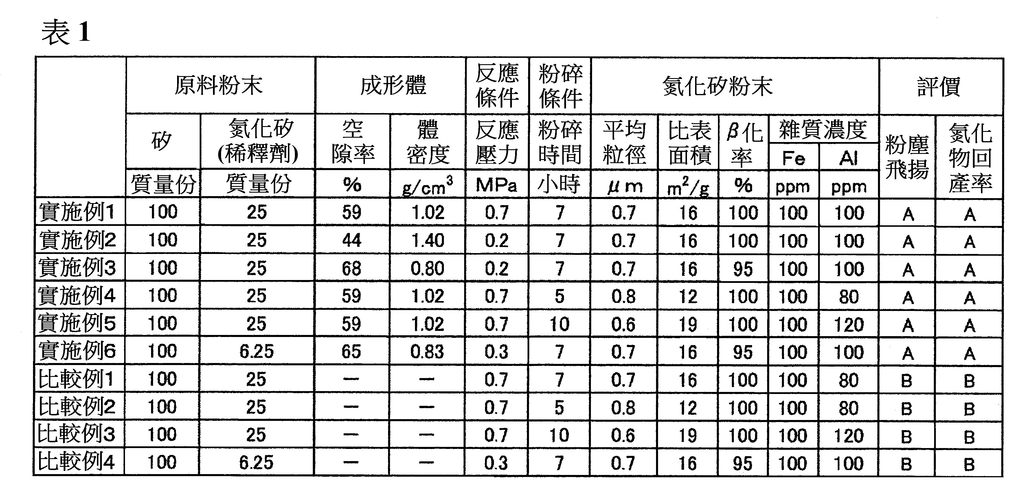
〈比較例5〉 於實施例1之氮化矽粉末之製造方法中,使成形體的空隙率成為30%之值,進行燃燒合成反應。此時,燃燒反應未充分地進行,於反應途中熄火而未反應物變多。<Comparative Example 5> In the method for producing silicon nitride powder of Example 1, the porosity of the molded body was set to a value of 30%, and the combustion synthesis reaction was performed. At this time, the combustion reaction did not proceed sufficiently, the flame was extinguished in the middle of the reaction, and unreacted substances increased.
〈比較例6〉 於實施例1之氮化矽粉末之製造方法中,將成形體的空隙率設為80%之值。此時,成形體變脆,操作性變差,難以設置於反應容器內。<Comparative Example 6> In the manufacturing method of silicon nitride powder of Example 1, the porosity of the molded body was set to a value of 80%. At this time, the molded body becomes brittle, and the operability deteriorates, making it difficult to install it in the reaction vessel.
可知藉由使用將粉末原料以成為指定的空隙率之方式所成形的原料,能抑制粉塵飛揚,同時能提高氮化物的回產率。又,可知即便使用所成形的原料,也與使用未成形的原料之情況同樣地,得到優異的燒結體。尚且,於使用未成形的原料所製作的氮化矽塊之表面上,主要殘留條紋狀的黑色未反應矽。由該條紋狀的形狀來看,茲認為未反應矽的殘留之原因為所填充的原料粉末中發生之龜裂。由於龜裂係從原料粉末之表面達到深的位置為止,故於使用未成形的原料所製作的氮化矽塊中,茲認為未反應矽係在從氮化矽塊之表面到深的位置為止殘留。而且,若刷洗不能可觀地削減氮化矽塊之表面,則無法從氮化矽塊來去除未反應矽,因此茲認為於使用未成形的原料所製作之氮化矽塊中,氮化物回產率低。 又,藉由於前述所成形的原料之周圍形成絕熱層,未反應物量為10%以下,取決於情況減低至5%以下者為可能。It can be seen that by using the raw material formed by forming the powder raw material into a predetermined void ratio, dust flying can be suppressed, and at the same time the nitride recovery rate can be improved. In addition, it can be seen that even when the formed raw material is used, an excellent sintered body is obtained in the same manner as in the case of using an unshaped raw material. Moreover, on the surface of the silicon nitride block made of unformed raw materials, mainly striped black unreacted silicon remains. Judging from the striped shape, it is believed that the cause of the remaining unreacted silicon is cracks in the filled raw material powder. Since the cracking is from the surface of the raw material powder to the deep position, in the silicon nitride block made from the unformed raw material, it is considered that the unreacted silicon is from the surface of the silicon nitride block to the deep position. Residue. Moreover, if the scrubbing fails to reduce the surface of the silicon nitride block appreciably, the unreacted silicon cannot be removed from the silicon nitride block. Therefore, it is believed that the nitride is reproduced in the silicon nitride block made from unformed raw materials. The rate is low. In addition, due to the formation of an insulating layer around the formed raw material, the amount of unreacted material is 10% or less, depending on the situation, it may be reduced to 5% or less.
1A~1C:成形體 2:耐熱性容器 3:絕熱層1A~1C: formed body 2: Heat resistant container 3: Insulation layer
[圖1]係顯示反應容器內的成形體之配置的一例之模型圖。 [圖2]係顯示反應容器內的成形體之配置的一例之模型圖。 [圖3(a)~(c)]各自係顯示反應容器內的成形體之配置的一例之模型圖。 [圖4]係顯示反應容器內的成形體之配置的一例之模型圖。 [圖5]係顯示在成形體之上方所形成的絕熱層的一例之模型圖。 [圖6]係顯示在成形體之上方、下方及側方所形成的絕熱層的一例之模型圖。[Fig. 1] is a model diagram showing an example of the arrangement of the formed body in the reaction vessel. [Fig. 2] is a model diagram showing an example of the arrangement of the formed body in the reaction vessel. [FIG. 3(a)-(c)] Each is a model diagram showing an example of the arrangement of the molded body in the reaction vessel. [Fig. 4] is a model diagram showing an example of the arrangement of the molded body in the reaction vessel. [Fig. 5] is a model diagram showing an example of the heat insulating layer formed on the upper side of the molded body. [Fig. 6] is a model diagram showing an example of the heat insulating layer formed on the upper, lower, and lateral sides of the molded body.
1B:成形體 1B: formed body
2:耐熱性容器 2: Heat resistant container
Claims (5)
Applications Claiming Priority (2)
| Application Number | Priority Date | Filing Date | Title |
|---|---|---|---|
| JP2019220570 | 2019-12-05 | ||
| JP2019-220570 | 2019-12-05 |
Publications (1)
| Publication Number | Publication Date |
|---|---|
| TW202128553A true TW202128553A (en) | 2021-08-01 |
Family
ID=76222309
Family Applications (1)
| Application Number | Title | Priority Date | Filing Date |
|---|---|---|---|
| TW109142732A TW202128553A (en) | 2019-12-05 | 2020-12-04 | Metal nitride production method |
Country Status (7)
| Country | Link |
|---|---|
| US (1) | US20230002229A1 (en) |
| EP (1) | EP4071110A4 (en) |
| JP (1) | JP7623955B2 (en) |
| KR (1) | KR20220110742A (en) |
| CN (1) | CN114728787A (en) |
| TW (1) | TW202128553A (en) |
| WO (1) | WO2021112145A1 (en) |
Families Citing this family (1)
| Publication number | Priority date | Publication date | Assignee | Title |
|---|---|---|---|---|
| JP2024030688A (en) * | 2022-08-25 | 2024-03-07 | 株式会社トクヤマ | Raw material compact for combustion synthesis |
Family Cites Families (19)
| Publication number | Priority date | Publication date | Assignee | Title |
|---|---|---|---|---|
| JPS5627441B1 (en) * | 1970-05-15 | 1981-06-25 | ||
| US4269654A (en) * | 1977-11-18 | 1981-05-26 | Rca Corporation | Silicon nitride and silicon oxide etchant |
| JPS62162608A (en) * | 1986-01-09 | 1987-07-18 | Mitsue Koizumi | Production of silicon nitride fine powder |
| JPH0825729B2 (en) * | 1990-09-17 | 1996-03-13 | 東京工業大学長 | Combustion synthesis method of high-purity TiN |
| US5453407A (en) * | 1994-02-14 | 1995-09-26 | National Science Council | Method for producing nitride ceramic powders |
| JPH1160217A (en) * | 1997-08-13 | 1999-03-02 | Shin Etsu Chem Co Ltd | Method for producing silicon nitride powder |
| JP4082803B2 (en) * | 1998-10-28 | 2008-04-30 | 電気化学工業株式会社 | Method for producing silicon nitride powder |
| JP4256012B2 (en) | 1999-03-23 | 2009-04-22 | 修 山田 | Method for producing BN, AlN or Si3N4 by combustion synthesis reaction |
| CN100339338C (en) * | 2003-07-17 | 2007-09-26 | 旭硝子株式会社 | Method for producing a silicon nitride filter |
| JP4348429B2 (en) * | 2003-10-20 | 2009-10-21 | 独立行政法人産業技術総合研究所 | Porous silicon nitride and method for producing the same |
| KR20050122748A (en) * | 2004-06-25 | 2005-12-29 | 한국에너지기술연구원 | Fabrication method of silicon nitride ceramics by nitrided pressureless sintering process |
| KR101155549B1 (en) * | 2009-11-24 | 2012-06-19 | 한국기계연구원 | Manufacturing Methods of Porous Sintered Reaction-Bonded Silicon Nitride and Porous Sintered Reaction-Bonded Silicon Nitride Fabricated Thereby |
| TWI401206B (en) * | 2010-02-12 | 2013-07-11 | Univ Nat Cheng Kung | Manufacturing method for aln |
| CN103526153B (en) * | 2012-07-03 | 2017-10-24 | 山东科技大学 | A kind of nitriding method |
| CN104016693A (en) * | 2014-06-11 | 2014-09-03 | 上海大学 | Preparation method of carbide bonded silicon nitride fireproof material |
| CN104296366A (en) * | 2014-09-24 | 2015-01-21 | 闫四清 | Silicon nitride utilized electric boiler |
| JP2020023406A (en) | 2016-12-12 | 2020-02-13 | 宇部興産株式会社 | Method for producing high-purity silicon nitride powder |
| KR102643831B1 (en) * | 2018-02-28 | 2024-03-07 | 가부시끼가이샤 도꾸야마 | Method for producing silicon nitride powder |
| JP7185865B2 (en) * | 2019-01-09 | 2022-12-08 | 株式会社燃焼合成 | Method for producing spherical AlN particles |
-
2020
- 2020-12-02 CN CN202080081035.6A patent/CN114728787A/en active Pending
- 2020-12-02 KR KR1020227017822A patent/KR20220110742A/en not_active Ceased
- 2020-12-02 EP EP20895498.2A patent/EP4071110A4/en not_active Withdrawn
- 2020-12-02 WO PCT/JP2020/044936 patent/WO2021112145A1/en not_active Ceased
- 2020-12-02 JP JP2021562696A patent/JP7623955B2/en active Active
- 2020-12-02 US US17/781,489 patent/US20230002229A1/en active Pending
- 2020-12-04 TW TW109142732A patent/TW202128553A/en unknown
Also Published As
| Publication number | Publication date |
|---|---|
| EP4071110A1 (en) | 2022-10-12 |
| EP4071110A4 (en) | 2024-01-03 |
| JP7623955B2 (en) | 2025-01-29 |
| US20230002229A1 (en) | 2023-01-05 |
| KR20220110742A (en) | 2022-08-09 |
| JPWO2021112145A1 (en) | 2021-06-10 |
| WO2021112145A1 (en) | 2021-06-10 |
| CN114728787A (en) | 2022-07-08 |
Similar Documents
| Publication | Publication Date | Title |
|---|---|---|
| JP7358331B2 (en) | Method for manufacturing silicon nitride powder | |
| TW201829299A (en) | Method for producing high-purity silicon nitride powder | |
| TWI883173B (en) | Silicon nitride powder for sintering | |
| WO2018110564A1 (en) | Silicon nitride powder and method for producing silicon nitride sintered body | |
| Dong et al. | Fabrication of intermetallic NiAl by self-propagating high-temperature synthesis reaction using aluminium nanopowder under high pressure | |
| TW202140407A (en) | Silicon nitride powder, and method for producing silicon nitride sintered body | |
| TW202128553A (en) | Metal nitride production method | |
| CN112125315A (en) | Low-cost high-purity silicon hexaboride production process | |
| JP2000016805A (en) | Manufacturing method of aluminum nitride | |
| WO2017131108A1 (en) | Zirconium boride and method for producing same | |
| JP2525432B2 (en) | Normal pressure sintered boron nitride compact | |
| CN115038665B (en) | Method for producing aluminum nitride powder, aluminum nitride powder and package | |
| TW202134170A (en) | Method for producing metal nitride | |
| Lin et al. | Combustion synthesis method for synthesis of aluminum nitride powder using aluminum containers (II) | |
| JP7312690B2 (en) | Method for producing metal nitride, and ignition agent compact | |
| JP2024030688A (en) | Raw material compact for combustion synthesis | |
| JP7379142B2 (en) | Metal nitride manufacturing method, igniter and igniter molded body | |
| TW202140372A (en) | Silicon nitride powder, and method for producing silicon nitride sintered body | |
| CN120835865A (en) | Method for producing silicon nitride powder and method for producing silicon nitride sintered body | |
| JPH09241010A (en) | Production of silicon nitride | |
| JP2002522351A (en) | Process for producing ceramic powder using gas-suppressing or gas-generating additives |