TW202128609A - Method for producing n-vinylacetamide, and pyrolysis device - Google Patents
Method for producing n-vinylacetamide, and pyrolysis device Download PDFInfo
- Publication number
- TW202128609A TW202128609A TW109143224A TW109143224A TW202128609A TW 202128609 A TW202128609 A TW 202128609A TW 109143224 A TW109143224 A TW 109143224A TW 109143224 A TW109143224 A TW 109143224A TW 202128609 A TW202128609 A TW 202128609A
- Authority
- TW
- Taiwan
- Prior art keywords
- raw material
- aforementioned
- evaporator
- superheater
- pyrolysis
- Prior art date
Links
- 238000000197 pyrolysis Methods 0.000 title claims abstract description 120
- 238000004519 manufacturing process Methods 0.000 title claims abstract description 73
- RQAKESSLMFZVMC-UHFFFAOYSA-N n-ethenylacetamide Chemical compound CC(=O)NC=C RQAKESSLMFZVMC-UHFFFAOYSA-N 0.000 title claims abstract description 44
- 239000002994 raw material Substances 0.000 claims abstract description 288
- 238000002309 gasification Methods 0.000 claims abstract description 67
- 238000001704 evaporation Methods 0.000 claims abstract description 34
- 230000008020 evaporation Effects 0.000 claims abstract description 26
- RYGPJMDKDKHOTB-UHFFFAOYSA-N n-(1-methoxyethyl)acetamide Chemical compound COC(C)NC(C)=O RYGPJMDKDKHOTB-UHFFFAOYSA-N 0.000 claims abstract description 25
- 238000009835 boiling Methods 0.000 claims abstract description 20
- 238000013021 overheating Methods 0.000 claims abstract description 14
- 238000011084 recovery Methods 0.000 claims description 129
- 239000007788 liquid Substances 0.000 claims description 88
- 238000011144 upstream manufacturing Methods 0.000 claims description 44
- 238000004064 recycling Methods 0.000 claims description 7
- IJGRMHOSHXDMSA-UHFFFAOYSA-N Atomic nitrogen Chemical compound N#N IJGRMHOSHXDMSA-UHFFFAOYSA-N 0.000 description 22
- 239000007789 gas Substances 0.000 description 22
- 238000002955 isolation Methods 0.000 description 15
- 238000000605 extraction Methods 0.000 description 13
- 238000006243 chemical reaction Methods 0.000 description 11
- 239000012295 chemical reaction liquid Substances 0.000 description 11
- 229910052757 nitrogen Inorganic materials 0.000 description 10
- DLFVBJFMPXGRIB-UHFFFAOYSA-N Acetamide Chemical compound CC(N)=O DLFVBJFMPXGRIB-UHFFFAOYSA-N 0.000 description 9
- 238000000034 method Methods 0.000 description 9
- 239000000463 material Substances 0.000 description 6
- 239000000376 reactant Substances 0.000 description 6
- -1 N-vinyl amide carboxylate Chemical class 0.000 description 4
- 230000017525 heat dissipation Effects 0.000 description 4
- 238000010438 heat treatment Methods 0.000 description 4
- 229920006395 saturated elastomer Polymers 0.000 description 4
- 230000001629 suppression Effects 0.000 description 4
- OKKJLVBELUTLKV-UHFFFAOYSA-N Methanol Chemical compound OC OKKJLVBELUTLKV-UHFFFAOYSA-N 0.000 description 3
- 238000012546 transfer Methods 0.000 description 3
- 238000010521 absorption reaction Methods 0.000 description 2
- 230000033228 biological regulation Effects 0.000 description 2
- 230000000052 comparative effect Effects 0.000 description 2
- 238000012790 confirmation Methods 0.000 description 2
- 229910001873 dinitrogen Inorganic materials 0.000 description 2
- 238000012423 maintenance Methods 0.000 description 2
- 238000005192 partition Methods 0.000 description 2
- 239000000126 substance Substances 0.000 description 2
- 238000009834 vaporization Methods 0.000 description 2
- 230000008016 vaporization Effects 0.000 description 2
- 239000002250 absorbent Substances 0.000 description 1
- 230000002745 absorbent Effects 0.000 description 1
- 238000009825 accumulation Methods 0.000 description 1
- 150000001412 amines Chemical class 0.000 description 1
- 230000000903 blocking effect Effects 0.000 description 1
- 230000000694 effects Effects 0.000 description 1
- 230000005674 electromagnetic induction Effects 0.000 description 1
- 239000008394 flocculating agent Substances 0.000 description 1
- 239000011344 liquid material Substances 0.000 description 1
- 239000000178 monomer Substances 0.000 description 1
- ZQXSMRAEXCEDJD-UHFFFAOYSA-N n-ethenylformamide Chemical compound C=CNC=O ZQXSMRAEXCEDJD-UHFFFAOYSA-N 0.000 description 1
- 229920000642 polymer Polymers 0.000 description 1
- 239000002562 thickening agent Substances 0.000 description 1
- 229920002554 vinyl polymer Polymers 0.000 description 1
Images


Classifications
-
- C—CHEMISTRY; METALLURGY
- C07—ORGANIC CHEMISTRY
- C07C—ACYCLIC OR CARBOCYCLIC COMPOUNDS
- C07C231/00—Preparation of carboxylic acid amides
- C07C231/12—Preparation of carboxylic acid amides by reactions not involving the formation of carboxamide groups
-
- B—PERFORMING OPERATIONS; TRANSPORTING
- B01—PHYSICAL OR CHEMICAL PROCESSES OR APPARATUS IN GENERAL
- B01J—CHEMICAL OR PHYSICAL PROCESSES, e.g. CATALYSIS OR COLLOID CHEMISTRY; THEIR RELEVANT APPARATUS
- B01J12/00—Chemical processes in general for reacting gaseous media with gaseous media; Apparatus specially adapted therefor
- B01J12/005—Chemical processes in general for reacting gaseous media with gaseous media; Apparatus specially adapted therefor carried out at high temperatures, e.g. by pyrolysis
-
- B—PERFORMING OPERATIONS; TRANSPORTING
- B01—PHYSICAL OR CHEMICAL PROCESSES OR APPARATUS IN GENERAL
- B01J—CHEMICAL OR PHYSICAL PROCESSES, e.g. CATALYSIS OR COLLOID CHEMISTRY; THEIR RELEVANT APPARATUS
- B01J19/00—Chemical, physical or physico-chemical processes in general; Their relevant apparatus
- B01J19/0006—Controlling or regulating processes
- B01J19/0013—Controlling the temperature of the process
-
- C—CHEMISTRY; METALLURGY
- C07—ORGANIC CHEMISTRY
- C07C—ACYCLIC OR CARBOCYCLIC COMPOUNDS
- C07C231/00—Preparation of carboxylic acid amides
- C07C231/22—Separation; Purification; Stabilisation; Use of additives
-
- C—CHEMISTRY; METALLURGY
- C07—ORGANIC CHEMISTRY
- C07C—ACYCLIC OR CARBOCYCLIC COMPOUNDS
- C07C233/00—Carboxylic acid amides
- C07C233/01—Carboxylic acid amides having carbon atoms of carboxamide groups bound to hydrogen atoms or to acyclic carbon atoms
- C07C233/02—Carboxylic acid amides having carbon atoms of carboxamide groups bound to hydrogen atoms or to acyclic carbon atoms having nitrogen atoms of carboxamide groups bound to hydrogen atoms or to carbon atoms of unsubstituted hydrocarbon radicals
- C07C233/04—Carboxylic acid amides having carbon atoms of carboxamide groups bound to hydrogen atoms or to acyclic carbon atoms having nitrogen atoms of carboxamide groups bound to hydrogen atoms or to carbon atoms of unsubstituted hydrocarbon radicals with carbon atoms of carboxamide groups bound to acyclic carbon atoms of an acyclic saturated carbon skeleton
- C07C233/05—Carboxylic acid amides having carbon atoms of carboxamide groups bound to hydrogen atoms or to acyclic carbon atoms having nitrogen atoms of carboxamide groups bound to hydrogen atoms or to carbon atoms of unsubstituted hydrocarbon radicals with carbon atoms of carboxamide groups bound to acyclic carbon atoms of an acyclic saturated carbon skeleton having the nitrogen atoms of the carboxamide groups bound to hydrogen atoms or to acyclic carbon atoms
-
- B—PERFORMING OPERATIONS; TRANSPORTING
- B01—PHYSICAL OR CHEMICAL PROCESSES OR APPARATUS IN GENERAL
- B01J—CHEMICAL OR PHYSICAL PROCESSES, e.g. CATALYSIS OR COLLOID CHEMISTRY; THEIR RELEVANT APPARATUS
- B01J2219/00—Chemical, physical or physico-chemical processes in general; Their relevant apparatus
- B01J2219/00049—Controlling or regulating processes
- B01J2219/00051—Controlling the temperature
- B01J2219/00121—Controlling the temperature by direct heating or cooling
- B01J2219/00128—Controlling the temperature by direct heating or cooling by evaporation of reactants
Landscapes
- Chemical & Material Sciences (AREA)
- Organic Chemistry (AREA)
- Chemical Kinetics & Catalysis (AREA)
- Organic Low-Molecular-Weight Compounds And Preparation Thereof (AREA)
Abstract
本發明之提供可防止原料氣體(氣化原料)因再凝縮而液化,抑制熱解反應器之凝集物導致的阻塞問題,可以長期間安定地連續運轉之N-乙烯基乙醯胺之製造方法。本發明之N-乙烯基乙醯胺之製造方法,包含:將含有N-(1-甲氧基乙基)乙醯胺(MEA)的原料供給至蒸發器之供給步驟,以前述蒸發器使前述原料蒸發,成為氣化原料之蒸發步驟,將前述氣化原料供給至過熱器,以使前述氣化原料之過熱溫度成為比前述N-(1-甲氧基乙基)乙醯胺的過熱器內壓下之沸點還高5℃的溫度(前述N-(1-甲氧基乙基)乙醯胺的過熱器內壓下之沸點+5℃)以上200℃以下的方式進行過熱之過熱步驟,將前述過熱的氣化原料供給至熱解反應器,進行熱解之熱解步驟;前述原料中之前述N-(1-甲氧基乙基)乙醯胺的含量為80~100質量百分比(質量%)。The present invention provides a method for producing N-vinylacetamide that can prevent the raw material gas (gasification raw material) from being liquefied due to recondensation, suppress the clogging problem caused by the agglomerates of the pyrolysis reactor, and can operate stably and continuously for a long period of time . The method for producing N-vinylacetamide of the present invention includes: a supply step of supplying a raw material containing N-(1-methoxyethyl)acetamide (MEA) to an evaporator, using the aforementioned evaporator The aforementioned raw material is evaporated to become the evaporation step of the gasification raw material. The gasification raw material is supplied to the superheater so that the superheating temperature of the gasification raw material becomes higher than the superheat of the aforementioned N-(1-methoxyethyl)acetamide The boiling point under the internal pressure of the vessel is also 5℃ higher (the boiling point of the aforementioned N-(1-methoxyethyl)acetamide under the internal pressure of the superheater + 5℃) above 200℃ and overheating is carried out. Step: Supply the overheated gasification raw material to the pyrolysis reactor for the pyrolysis step of pyrolysis; the content of the N-(1-methoxyethyl)acetamine in the raw material is 80-100 mass Percentage (mass%).
Description
本發明係關於N-乙烯基乙醯胺之製造方法及熱解裝置。The present invention relates to a manufacturing method and pyrolysis device of N-vinylacetamide.
關於N-乙烯基羧酸醯胺之製造方法,至此已有多種方法被提出(例如參照專利文獻1)。在專利文獻1所記載的製造方法,揭示了使N-(2-烷氧基乙基)羧酸醯胺原料蒸發而熱解之N-乙烯基羧酸醯胺之製造方法。如此,於藉由熱解來製造N-乙烯基羧酸醯胺之方法,例如,會因為對大氣的散熱、在熱解反應器(熱解步驟)之吸熱、機械故障導致壓力變化、熱源的供給停止等因素,而使原料氣體(氣化原料)在蒸發器、連接蒸發器與熱解反應器的配管內、或者熱解反應器內因再凝縮而液化,液化的原料流入高溫的熱解反應器的情形。結果,有(i)液化原料流入熱解反應器的軟管內壁,(ii)液化原料在熱解反應器的軟管內壁再蒸發之前就高分子化產生瀝青狀或固體狀的凝集物(亦稱為harz),引起熱解反應器的軟管阻塞問題的情形,安定地運作變得困難。 [先前技術文獻] [專利文獻]Regarding the production method of N-vinyl carboxylic acid amide, various methods have been proposed so far (for example, refer to Patent Document 1). The production method described in Patent Document 1 discloses a production method of N-vinyl amide carboxylate by evaporating and pyrolyzing the raw material of N-(2-alkoxyethyl) amide carboxylate. In this way, in the method of producing N-vinyl amide carboxylate by pyrolysis, for example, due to heat dissipation to the atmosphere, heat absorption in the pyrolysis reactor (pyrolysis step), mechanical failure, pressure changes, and heat sources Supply stop and other factors cause the raw material gas (vaporized raw material) to liquefy due to recondensation in the evaporator, the pipe connecting the evaporator and the pyrolysis reactor, or the pyrolysis reactor, and the liquefied raw material flows into the high-temperature pyrolysis reaction The situation of the device. As a result, (i) the liquefied material flows into the inner wall of the hose of the pyrolysis reactor, and (ii) the liquefied material is polymerized before the inner wall of the hose of the pyrolysis reactor evaporates to produce asphalt-like or solid-like aggregates. (Also known as harz), it is difficult to operate stably when the hoses of the pyrolysis reactor are blocked. [Prior Technical Literature] [Patent Literature]
[專利文獻1]國際公開第2017/002494號公報[Patent Document 1] International Publication No. 2017/002494
[發明所欲解決之課題][The problem to be solved by the invention]
本發明之目的在於提供可解決前述問題,防止原料氣體(氣化原料)因再凝縮而液化,抑制熱解反應器之凝集物導致的阻塞問題,可以長期間安定地連續運轉之N-乙烯基乙醯胺之製造方法。 [供解決課題之手段]The object of the present invention is to provide an N-vinyl which can solve the aforementioned problems, prevent the raw material gas (gasification raw material) from being liquefied due to recondensation, suppress the clogging problem caused by the agglomerates of the pyrolysis reactor, and can operate stably and continuously for a long period of time. The manufacturing method of acetamide. [Means for problem solving]
本案發明人等,銳意研究解決前述課題的結果,發現在蒸發器(蒸發步驟)與熱解反應器(熱解步驟)之間設過熱器(過熱步驟),在該過熱器(過熱步驟),滿足以下至少任一:(i)使原料氣體(氣化原料)之過熱溫度成為比N-(1-甲氧基乙基)乙醯胺的過熱器內壓下之沸點還高特定溫度(5℃)的溫度(N-(1-甲氧基乙基)乙醯胺的過熱器內壓下之沸點+5℃)以上200℃以下的方式進行過熱,以及(ii)對原料氣體(氣化原料)賦予特定熱量,可以防止原料氣體(氣化原料)因再凝縮而液化,從而完成本發明。 亦即,本發明提供以下(1)~(15)。 (1)N-乙烯基乙醯胺之製造方法,包含:將含有N-(1-甲氧基乙基)乙醯胺(MEA)的原料供給至蒸發器之供給步驟,以前述蒸發器使前述原料蒸發而使其成為氣化原料之蒸發步驟,將前述氣化原料供給至過熱器,以使前述氣化原料之過熱溫度成為比前述N-(1-甲氧基乙基)乙醯胺的過熱器內壓下之沸點還高5℃的溫度(前述N-(1-甲氧基乙基)乙醯胺的過熱器內壓下之沸點+5℃)以上200℃以下的方式使前述氣化原料過熱之過熱步驟,將已過熱的前述氣化原料供給至熱解反應器,進行熱解之熱解步驟;前述原料中之前述N-(1-甲氧基乙基)乙醯胺的含量為80~100質量百分比(質量%)。 (2)N-乙烯基乙醯胺之製造方法,包含:將含有N-(1-甲氧基乙基)乙醯胺(MEA)的原料供給至蒸發器之供給步驟,以前述蒸發器使前述原料蒸發而使其成為氣化原料之蒸發步驟,將前述氣化原料供給至過熱器,對前述氣化原料賦予1.0kJ/moL以上之熱量使前述氣化原料過熱之過熱步驟,將已過熱的前述氣化原料供給至熱解反應器,進行熱解之熱解步驟;前述原料中之前述N-(1-甲氧基乙基)乙醯胺的含量為80~100質量百分比(質量%)。 (3)如前述(1)或(2)之N-乙烯基乙醯胺之製造方法,前述蒸發步驟在減壓下進行。 (4)如前述(1)~(3)之任一之N-乙烯基乙醯胺之製造方法,前述熱解步驟在減壓下進行。 (5)如前述(1)~(4)之任一之N-乙烯基乙醯胺之製造方法,前述蒸發器為流下液膜式。 (6)如前述(1)~(4)之任一之N-乙烯基乙醯胺之製造方法,前述蒸發器為強制液膜式。 (7)如前述(1)~(6)之任一之N-乙烯基乙醯胺之製造方法,前述蒸發器的下游端與前述過熱器的上游端,透過第1配管連接,前述第1配管的下游端的位置,在前述第1配管中為最高。 (8)如前述(1)~(7)之任一之N-乙烯基乙醯胺之製造方法,前述過熱器的下游端與前述熱解反應器的上游端,透過第2配管連接,前述第2配管的上游端的位置,在前述第2配管中為最高。 (9)如前述(1)~(8)之任一之N-乙烯基乙醯胺之製造方法,前述蒸發步驟與前述熱解步驟之間,進而包含把被供給至前述蒸發器的前述原料中之未氣化的液體原料及前述氣化原料的一部分液化而成的液體原料予以回收之回收步驟;前述回收步驟,係藉由前述蒸發器與前述熱解反應器之間所具備的原料回收裝置,回收前述液體原料之步驟。 (10)如前述(9)之N-乙烯基乙醯胺之製造方法,前述蒸發器的下游端與前述原料回收裝置的上游端接合著。 (11)如前述(9)或(10)之N-乙烯基乙醯胺之製造方法,前述原料回收裝置的下游端與前述過熱器的上游端接合著。 (12)如前述(9)~(11)之任一之N-乙烯基乙醯胺之製造方法,前述氣化原料,於經過前述原料回收裝置後被供給至前述熱解反應器。 (13)如前述(9)~(12)之任一之N-乙烯基乙醯胺之製造方法,前述原料回收裝置,具有:供前述氣化原料流通的筒部、使流通於前述筒部內的前述氣化原料的氣流的一部分或全部衝突,將被供給至前述蒸發器的前述原料中之未氣化的液體原料以及前述氣化原料的一部分液化而成的液體原料予以回收之回收部、以及將藉由前述回收部回收的前述液體原料排出至前述筒部的外部之排出配管。 (14)熱解裝置,具備:可使原料蒸發而產生氣化原料之蒸發器,被連接於前述蒸發器,可使前述氣化原料成為比N-(1-甲氧基乙基)乙醯胺的過熱器內壓下之沸點還高5℃的溫度(前述N-(1-甲氧基乙基)乙醯胺的過熱器內壓下之沸點+5℃)以上200℃以下進行過熱之過熱器,被連接於前述過熱器,可使前述過熱的氣化原料熱解的熱解反應器。 [發明之效果]The inventors of the present case have intensively studied the results of solving the aforementioned problems and found that a superheater (superheating step) is provided between the evaporator (evaporation step) and the pyrolysis reactor (pyrolysis step), and in the superheater (superheating step), Meet at least one of the following: (i) Make the superheating temperature of the raw material gas (gasification raw material) a specific temperature higher than the boiling point of the N-(1-methoxyethyl)acetamide under the superheater internal pressure (5 ℃) temperature (the boiling point of N-(1-methoxyethyl) acetamide under the superheater internal pressure + 5℃) above 200℃, and (ii) the raw material gas (vaporization) The raw material) imparts specific heat to prevent the raw material gas (vaporized raw material) from being liquefied due to recondensation, thereby completing the present invention. That is, the present invention provides the following (1) to (15). (1) A method for producing N-vinylacetamide, comprising: a supply step of supplying a raw material containing N-(1-methoxyethyl)acetamide (MEA) to an evaporator, using the aforementioned evaporator The evaporation step of evaporating the aforementioned raw material to make it into a gasification raw material, supplying the aforementioned gasification raw material to a superheater so that the superheating temperature of the aforementioned gasification raw material becomes higher than that of the aforementioned N-(1-methoxyethyl)acetamide The boiling point under the superheater internal pressure is 5℃ higher (the boiling point of the aforementioned N-(1-methoxyethyl)acetamide under the superheater internal pressure + 5℃) above 200℃ and below 200℃. The superheating step of the gasification raw material overheating, the above-mentioned gasification raw material that has been overheated is supplied to the pyrolysis reactor, and the pyrolysis step of pyrolysis is performed; the aforementioned N-(1-methoxyethyl)acetamine in the aforementioned raw material The content is 80-100 mass percent (mass%). (2) A method for producing N-vinylacetamide, comprising: a supply step of supplying a raw material containing N-(1-methoxyethyl)acetamide (MEA) to an evaporator, using the aforementioned evaporator The vaporization step of evaporating the aforementioned raw material to make it into a gasification raw material, the superheating step of supplying the aforementioned gasification raw material to a superheater, and applying a heat of 1.0 kJ/moL or more to the aforementioned gasification raw material to overheat the aforementioned gasification raw material, the overheated The aforementioned gasification raw material is supplied to the pyrolysis reactor for the pyrolysis step of pyrolysis; the content of the aforementioned N-(1-methoxyethyl)acetamine in the aforementioned raw material is 80-100% by mass (mass% ). (3) The method for producing N-vinylacetamide according to (1) or (2), wherein the evaporation step is carried out under reduced pressure. (4) The method for producing N-vinylacetamide according to any one of (1) to (3) above, wherein the pyrolysis step is carried out under reduced pressure. (5) The method for producing N-vinylacetamide according to any one of (1) to (4) above, wherein the evaporator is of the down-flow liquid film type. (6) The method for producing N-vinylacetamide according to any one of (1) to (4) above, wherein the evaporator is a forced liquid film type. (7) The method for producing N-vinylacetamide according to any one of (1) to (6) above, wherein the downstream end of the evaporator and the upstream end of the superheater are connected through a first pipe, and the first The position of the downstream end of the piping is the highest in the above-mentioned first piping. (8) The method for producing N-vinylacetamide according to any one of (1) to (7) above, wherein the downstream end of the superheater and the upstream end of the pyrolysis reactor are connected through a second pipe, and the The position of the upstream end of the second piping is the highest among the above-mentioned second piping. (9) The method for producing N-vinylacetamide according to any one of (1) to (8), wherein between the evaporation step and the pyrolysis step, the raw material supplied to the evaporator is further included The unvaporized liquid raw material and the liquid raw material liquefied by a part of the gasified raw material are recovered in the recovery step; the recovery step is the recovery of the raw material provided between the evaporator and the pyrolysis reactor Device, the step of recovering the aforementioned liquid raw material. (10) The method for producing N-vinylacetamide described in (9) above, wherein the downstream end of the evaporator is joined to the upstream end of the raw material recovery device. (11) The method for producing N-vinylacetamide according to (9) or (10), wherein the downstream end of the raw material recovery device is joined to the upstream end of the superheater. (12) The method for producing N-vinylacetamide according to any one of (9) to (11) above, wherein the gasification raw material is supplied to the pyrolysis reactor after passing through the raw material recovery device. (13) The method for producing N-vinylacetamide according to any one of (9) to (12) above, wherein the raw material recovery device has: a cylinder for the gasification raw material to circulate, and to circulate in the cylinder A part or all of the gasification raw material flow conflicts with each other, and the unvaporized liquid raw material and the liquid raw material liquefied by a part of the gasification raw material among the raw materials supplied to the evaporator are recovered in the recovery section, And a discharge pipe that discharges the liquid raw material recovered by the recovery part to the outside of the cylinder part. (14) A pyrolysis device equipped with: an evaporator that can evaporate raw materials to produce gasified raw materials, and is connected to the evaporator to make the gasified raw materials more The boiling point of the amine under the superheater internal pressure is 5℃ higher (the boiling point of the aforementioned N-(1-methoxyethyl) acetamide under the superheater internal pressure + 5℃) above 200℃ for overheating. The superheater is a pyrolysis reactor that is connected to the superheater and can pyrolyze the superheated gasification raw material. [Effects of Invention]
根據本發明的話,可以提供可防止原料氣體(氣化原料)因再凝縮而液化,抑制熱解反應器之凝集物導致的阻塞問題,可以長期間安定地連續運轉之N-乙烯基乙醯胺之製造方法。According to the present invention, it is possible to provide N-vinylacetamide which can prevent the raw material gas (gasification raw material) from being liquefied due to recondensation, suppress the clogging problem caused by the agglomerates of the pyrolysis reactor, and can operate stably and continuously for a long period of time. The manufacturing method.
於本說明書,較佳的規定可以任意選擇,較佳的規定彼此組合可說是更佳的。 於本說明書,「XX~YY」之記載,意味著「XX以上YY以下」。 於本說明書,較佳的數值範圍(例如含量等之範圍),分階段記載的下限值及上限值,分別可以獨立而組合。例如,由「較佳為10~90,更佳為30~60」之記載,也可以組合「較佳的下限值(10)」與「較佳的上限值(60)」,而得到「10~60」。In this specification, preferred regulations can be selected arbitrarily, and it can be said that better regulations are combined with each other. In this manual, the description of "XX~YY" means "more than XX and less than YY". In this specification, the preferable numerical range (for example, the range of content, etc.), the lower limit and the upper limit described in stages, can be combined independently. For example, from the description of "preferably 10 to 90, more preferably 30 to 60", it is also possible to combine "preferred lower limit (10)" and "preferred upper limit (60)" to obtain "10-60".
[N-乙烯基乙醯胺之製造方法] 相關於本發明的實施型態之N-乙烯基乙醯胺之製造方法,如圖1所示,包含:供給步驟S1、蒸發步驟S2、任意的回收步驟S3、過熱步驟S4、與熱解步驟S5。以下,詳細說明關於本發明的實施型態之N-乙烯基乙醯胺之製造方法。[The manufacturing method of N-vinyl acetamide] The manufacturing method of N-vinylacetamide related to the embodiment of the present invention, as shown in FIG. 1, includes: supply step S1, evaporation step S2, optional recovery step S3, overheating step S4, and pyrolysis step S5. Hereinafter, the method for producing N-vinylacetamide according to the embodiment of the present invention will be described in detail.
(供給步驟S1) 供給步驟S1,是將含有N-(1-甲氧基乙基)乙醯胺(MEA)的原料供給至蒸發器的步驟。(Supply step S1) The supply step S1 is a step of supplying a raw material containing N-(1-methoxyethyl)acetamide (MEA) to the evaporator.
關於本發明實施型態之N-乙烯基乙醯胺之製造方法,作為原料的一部分或全部,使用下列一般式(1)所表示的N-(1-甲氧基乙基)乙醯胺。
【化學式1】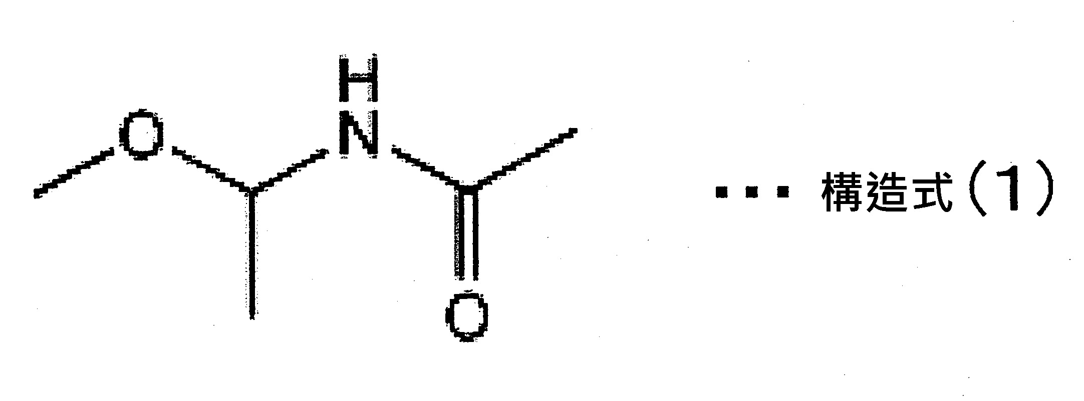
於供給步驟S1,原料往蒸發器的供給速度,隨蒸發器的尺寸及能力而有所不同,但由安定地使原料蒸發的觀點來看,以5~350kg/h為佳,10~150kg/h為更佳、15~80kg/h進而又更佳。In the feeding step S1, the feed rate of the raw material to the evaporator varies with the size and capacity of the evaporator, but from the viewpoint of stably evaporating the raw material, it is preferably 5 to 350 kg/h, and 10 to 150 kg/ h is more preferable, and 15 to 80 kg/h is even more preferable.
(蒸發步驟S2) 蒸發步驟S2,係以蒸發器使原料蒸發、形成氣化原料之步驟。 在蒸發步驟S2使用的蒸發器,沒有特別限制,由效率佳地實施原料蒸發的觀點來看,以流下液膜式蒸發器及強制液膜式蒸發器之任一為佳。(Evaporation step S2) The evaporation step S2 is a step of evaporating the raw material with an evaporator to form a gasified raw material. The evaporator used in the evaporating step S2 is not particularly limited. From the viewpoint of efficiently evaporating the raw material, any one of a downflow liquid film evaporator and a forced liquid film evaporator is preferable.
蒸發步驟S2,雖可以是在減壓下或常壓下進行,最好是在減壓下進行。蒸發步驟S2之反應壓力,具體而言,在1~30kPa下進行為佳,在3~25kPa下進行更佳,在5~22kPa下進行又更佳。 蒸發步驟S2,需要在加熱蒸發而形成氣化原料的溫度下進行,具體而言,在100~200℃下進行為佳,在110~190℃下進行更佳,在120~180℃下進行又更佳。Although the evaporation step S2 may be carried out under reduced pressure or normal pressure, it is preferably carried out under reduced pressure. The reaction pressure of the evaporation step S2, specifically, is preferably carried out at 1-30 kPa, more preferably carried out at 3-25 kPa, and even more preferably carried out at 5-22 kPa. The evaporation step S2 needs to be carried out at a temperature at which the vaporized raw material is formed by heating and evaporating. Specifically, it is preferably carried out at 100-200°C, more preferably carried out at 110-190°C, and carried out at 120-180°C. Better.
於蒸發步驟S2,由使蒸發器的傳熱面積更小使蒸發器更小型化的觀點來看,以提供使原料蒸發的最低限度必要的熱量為佳。 在蒸發步驟S2提供的熱量超過使原料蒸發的最低限度必要的熱量的場合,應當要提供更為充分的熱量以供向大氣散熱或是熱解反應步驟之吸熱。In the evaporation step S2, from the viewpoint of reducing the heat transfer area of the evaporator and making the evaporator more compact, it is preferable to provide the minimum heat necessary to evaporate the raw material. Where the heat provided by the evaporation step S2 exceeds the minimum heat required to evaporate the raw materials, more sufficient heat should be provided for heat dissipation to the atmosphere or endothermic heat in the pyrolysis reaction step.
(回收步驟S3) 回收步驟S3,是在蒸發步驟S2與熱解步驟S5之間,把被供給至蒸發器的原料中未氣化的液體原料及氣化原料的一部分液化而成的液體原料予以回收之任意的步驟。氣化的狀態之氣化原料往熱解步驟供給。又,此回收步驟S3,以藉由蒸發器與熱解反應器之間的原料回收裝置來進行為佳。 在圖1,為蒸發步驟S2、回收步驟S3、過熱步驟S4的順序,但不以此為限,例如亦可為蒸發步驟S2、過熱步驟S4、回收步驟S3的順序。(Recovery step S3) The recovery step S3 is an optional step between the evaporation step S2 and the pyrolysis step S5 to recover the unvaporized liquid raw material and the liquid raw material obtained by liquefying a part of the vaporized raw material among the raw materials supplied to the evaporator. . The gasified raw materials in the gasified state are supplied to the pyrolysis step. Moreover, this recovery step S3 is preferably performed by a raw material recovery device between the evaporator and the pyrolysis reactor. In FIG. 1, the order of the evaporation step S2, the recovery step S3, and the overheating step S4, but not limited to this, for example, the order of the evaporation step S2, the overheating step S4, and the recovery step S3 can also be used.
液體原料即使只有少量被導入熱解反應器也會產生凝集物(harz),凝集物會閉塞熱解反應器使運轉無法繼續下去。即使凝集物沒有閉塞住熱解反應器的全容積,就靠閉塞住熱解反應器的原料導入側的些許容積就使得運轉無法繼續下去。藉著在回收步驟S3把液體原料回收到製造裝置的系統外的回收罐,可以更為確實地抑制液體原料往熱解反應器導入,結果可以達成長期間的繼續運轉。 製造裝置運轉時,作為產生液體原料的重要原因之例,可以舉出往大氣之散熱所導致、在熱解反應器(熱解步驟)之吸熱所導致、機械故障及操作疏失所致的運轉壓力變動所導致、機械故障及操作疏失所致的蒸發器熱源的停止或不足所導致、於蒸發器發生水垢(黑皮)減少傳熱面積而因蒸發不良所產生的,以及運轉開始時裝置的加熱還未充分時導入原料所致等。Even if only a small amount of liquid raw material is introduced into the pyrolysis reactor, agglomerates (harz) will be generated, which will block the pyrolysis reactor and make it impossible to continue the operation. Even if the agglomerate does not block the full volume of the pyrolysis reactor, the operation cannot be continued by blocking the small volume of the raw material introduction side of the pyrolysis reactor. By recovering the liquid raw material in the recovery tank outside the system of the manufacturing apparatus in the recovery step S3, the introduction of the liquid raw material into the pyrolysis reactor can be suppressed more reliably, and as a result, the continuous operation can be achieved for a long period of time. During the operation of manufacturing equipment, as an example of important causes of liquid raw materials, operating pressures caused by heat dissipation to the atmosphere, heat absorption in the pyrolysis reactor (pyrolysis step), mechanical failures and operational errors can be cited. The heat source of the evaporator is stopped or insufficient due to changes, mechanical failures and operational errors, scale (black skin) occurs in the evaporator, and the heat transfer area is reduced, resulting from poor evaporation, and heating of the device at the start of operation It is caused by the introduction of raw materials when it is not sufficient.
(過熱步驟S4) 過熱步驟S4,係將氣化原料供給至過熱器,進行過熱的步驟,是滿足以下至少任一之步驟:(i)使氣化原料之過熱溫度成為比N-(1-甲氧基乙基)乙醯胺的過熱器壓力下之沸點還高5℃的溫度(N-(1-甲氧基乙基)乙醯胺的過熱器內壓下之沸點+5℃)以上200℃以下,以及(ii)對氣化原料賦予1.0kJ/moL以上之熱量。 過熱步驟S4之氣化原料的過熱溫度,只要是比N-(1-甲氧基乙基)乙醯胺的過熱器內壓下之沸點還高5℃的溫度(N-(1-甲氧基乙基)乙醯胺的過熱器內壓下之沸點+5℃)以上200℃以下即可,沒有特別限制,以165~200℃為佳,170~195℃為更佳,173~190℃進而更佳。又,氣化原料的過熱溫度的上限,不是對沸點溫度加上該溫度之後的溫度,單純表示其上限的溫度。(Overheating step S4) The superheating step S4 is a step of supplying the gasification raw material to the superheater and performing the superheating. It is a step that satisfies at least one of the following: (i) the superheating temperature of the gasification raw material becomes higher ) The temperature at which the boiling point of acetamide under the superheater pressure is 5°C higher (the boiling point of N-(1-methoxyethyl)acetamide under the superheater internal pressure + 5°C) above 200°C, and (ii) Apply heat of 1.0kJ/moL or more to the gasification raw materials. The superheating temperature of the gasification raw material in the superheating step S4, as long as it is a temperature 5℃ higher than the boiling point of the N-(1-methoxyethyl)acetamide under the superheater internal pressure (N-(1-methoxy) The boiling point of acetyl amine under superheater internal pressure + 5°C) is not more than 200°C, and is not particularly limited. It is preferably from 165 to 200°C, more preferably from 170 to 195°C, and from 173 to 190°C And even better. In addition, the upper limit of the superheating temperature of the gasification raw material is not the temperature obtained by adding this temperature to the boiling point temperature, but simply represents the upper limit temperature.
在此,於本說明書,所謂「氣化原料的過熱溫度」意味著「氣化原料在過熱器內的最高溫度」,通常為過熱器的下游端之氣化原料的溫度(出口氣體溫度)。Here, in this specification, the "superheating temperature of the gasification raw material" means the "maximum temperature of the gasification raw material in the superheater", which is usually the temperature of the gasification raw material at the downstream end of the superheater (outlet gas temperature).
又,2.0MPaG(表壓)(工業上之蒸汽上限壓力)之熱媒飽和蒸汽溫度為215℃,所以由成本的觀點來看,過熱溫度的上限以200℃為佳。In addition, the saturated steam temperature of the heating medium of 2.0 MPaG (gauge pressure) (the upper limit of industrial steam pressure) is 215°C, so from the viewpoint of cost, the upper limit of the superheat temperature is preferably 200°C.
於過熱步驟S4作為對氣化原料提供的熱量,只要為1.0kJ/moL以上即可,沒有特別限制,以1.0~9.0kJ/moL為佳,1.5~8.0kJ/moL為更佳,2.0~7.0kJ/moL進而更佳。In the overheating step S4, as the heat provided to the gasification raw material, it is not particularly limited as long as it is 1.0kJ/moL or more, and is preferably 1.0~9.0kJ/moL, more preferably 1.5~8.0kJ/moL, 2.0~7.0 kJ/moL is even better.
前述氣化原料的過熱溫度及對氣化原料提供的熱量的下限值以下述方式決定。 從過熱器的出口到熱解裝置內的軟管,存在著不能加熱的處所(例如夾套(jacket)的接縫,熱解裝置的通道部分),於這些無法進行加熱的處所會因為熱解步驟的吸熱而使溫度降低。此在熱解步驟之吸熱導致的溫度降低,可由散熱量、反應速度、反應熱、滯留時間而算出。考慮算出的溫度降低與溫度誤差(界限,margin),決定氣化原料的過熱溫度及對氣化原料提供的熱量的下限值。The lower limit of the superheating temperature of the gasification raw material and the amount of heat supplied to the gasification raw material is determined in the following manner. From the outlet of the superheater to the hose in the pyrolysis device, there are places that cannot be heated (such as the joints of the jacket, the channel part of the pyrolysis device), and the places that cannot be heated will be caused by pyrolysis. The endotherm of the step lowers the temperature. The temperature drop caused by the endothermic heat in the pyrolysis step can be calculated from the amount of heat dissipation, reaction rate, reaction heat, and residence time. Considering the calculated temperature drop and temperature error (margin), the superheat temperature of the gasification raw material and the lower limit of the amount of heat supplied to the gasification raw material are determined.
另一方面,前述氣化原料的過熱溫度及對氣化原料提供的熱量的上限值以下述方式決定。 為了抑制在熱解裝置以外處反應進行太過度,有必要控制熱解反應使反應速度降低到比熱解裝置內的反應速度還充分低。因此,通常從控制熱解反應的觀點,設定氣化原料的過熱溫度及對氣化原料提供的熱量的上限值,但也有隨著可使用的熱媒溫度不同,而設定氣化原料的過熱溫度及對氣化原料提供的熱量的上限值的場合。On the other hand, the superheating temperature of the gasification raw material and the upper limit of the amount of heat supplied to the gasification raw material are determined as follows. In order to prevent the reaction from proceeding too much outside the pyrolysis device, it is necessary to control the pyrolysis reaction so that the reaction rate is lowered sufficiently than the reaction rate in the pyrolysis device. Therefore, usually from the viewpoint of controlling the pyrolysis reaction, the superheating temperature of the gasification raw material and the upper limit of the amount of heat supplied to the gasification raw material are set. The temperature and the upper limit of the heat supplied to the gasification raw materials.
過熱步驟S4,雖可以是在減壓下或常壓下進行,最好是在減壓下進行。過熱步驟S4之壓力,具體而言,在1~30kPa下進行為佳,在3~25kPa下進行更佳,在5~22kPa下進行又更佳。Although the superheating step S4 may be carried out under reduced pressure or normal pressure, it is preferably carried out under reduced pressure. Specifically, the pressure of the superheating step S4 is preferably performed at 1-30 kPa, more preferably performed at 3-25 kPa, and even more preferably performed at 5-22 kPa.
(熱解步驟S5) 熱解步驟S5,係將過熱的氣化原料供給至熱解反應器,予以熱解之步驟。供給至熱解反應器之氣化原料之氣流,如果是流入熱解反應器的氣流則無特別限制,可以是上升流,抑或下降流。(Pyrolysis step S5) The pyrolysis step S5 is a step in which the superheated gasification raw material is supplied to the pyrolysis reactor and pyrolyzed. The gas flow of the gasification raw material supplied to the pyrolysis reactor is not particularly limited if it is the gas flow into the pyrolysis reactor, and it may be an upward flow or a downward flow.
熱解步驟S5,雖可以是在減壓下或常壓下進行,最好是在減壓下進行。熱解步驟S5之反應壓力,具體而言,在1~30kPa下進行為佳,在3~25kPa下進行更佳,在5~22kPa下進行又更佳。 熱解步驟S5,由有效率地進行熱解之觀點而言,在250~500℃下進行為佳,在300~480℃下進行更佳,在350~450℃下進行又更佳。 熱解步驟S5之停留時間,由確實地進行熱解之觀點而言,為0.1~10秒佳,0.2~9秒更佳,0.3~8秒又更佳。 作為熱解反應器,由有效率地進行熱解之觀點而言,最好是多管式構造。Although the pyrolysis step S5 may be carried out under reduced pressure or normal pressure, it is preferably carried out under reduced pressure. The reaction pressure of the pyrolysis step S5, specifically, is preferably carried out at 1-30 kPa, more preferably carried out at 3-25 kPa, and even more preferably carried out at 5-22 kPa. The pyrolysis step S5 is preferably carried out at 250 to 500°C, more preferably carried out at 300 to 480°C, and still more preferably carried out at 350 to 450°C from the viewpoint of efficient pyrolysis. The residence time of the pyrolysis step S5 is preferably 0.1 to 10 seconds, more preferably 0.2 to 9 seconds, and more preferably 0.3 to 8 seconds from the viewpoint of surely performing pyrolysis. As a pyrolysis reactor, a multi-tube structure is preferable from the viewpoint of efficient pyrolysis.
被供給至熱解反應器的原料,以經回收步驟後的氣化原料為佳。藉著將經回收步驟後的氣化原料供給至熱解反應器,可以更為確實地抑制把液體原料導入熱解反應器,可以更為抑制凝集物(harz)的發生。The raw material supplied to the pyrolysis reactor is preferably the gasified raw material after the recovery step. By supplying the gasified raw material after the recovery step to the pyrolysis reactor, the introduction of the liquid raw material into the pyrolysis reactor can be suppressed more reliably, and the generation of harz can be further suppressed.
藉由以上的步驟而得到的N-乙烯基羧酸醯胺,係以下列構造式(2)表示者,可由包含於原料的構造式(1)表示的N-(1-甲氧基乙基)乙醯胺得到。
【化學式2】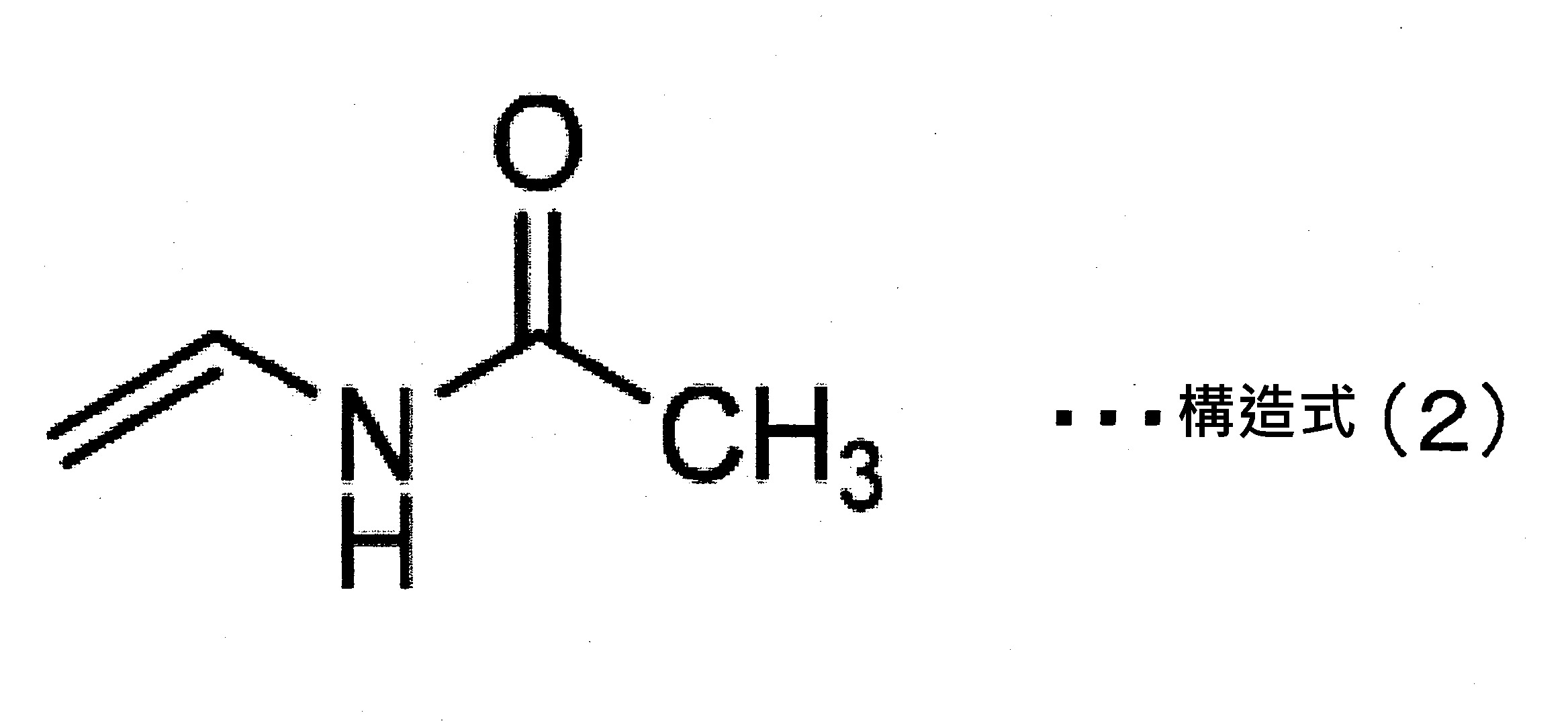
(第1製造裝置)
實施相關於本發明的實施形態之N-乙烯基乙醯胺之製造方法的第1製造裝置,如圖2所示,具備:實施供給步驟S1的原料供給裝置10,實施蒸發步驟S2的蒸發器(流下液膜式蒸發器)20A,實施回收步驟S3的原料回收裝置30A,實施過熱步驟S4的過熱器40A,實施熱解步驟S5的熱解反應器50,冷卻在熱解步驟S5被熱解的反應物進行液化的冷卻器60,貯留在冷卻器60液化的反應物之反應液承接器70。
原料供給裝置10的下游端透過配管12被連接於蒸發器20A的上游端,蒸發器20A的下游端被連接於原料回收裝置30A的上游端,原料回收裝置30A的下游端被連接於過熱器40A的上游端,過熱器40A的下游端被連接於熱解反應器50的上游端,熱解反應器50的下游端被連接於冷卻器60的上游端,冷卻器60的下游端被連接於反應液承接器70的上游端。
流下液膜式蒸發器,是使液狀的原料以傳送於蒸發管內面的方式膜狀地流下而使蒸發之蒸發器,例如,是在外殼內部設置多數軟管,使液體於這些軟管的內壁流下的構造的蒸發器。過熱器40A,具有與蒸餾器20A同樣的構造。
原料回收裝置30A,被配置把回收的液體原料予以回收之回收罐42。
於反應液承接器70,設有壓力泵71,可以藉由壓力泵71調整製造裝置全體的壓力。製造裝置全體的壓力,可以藉由設於反應液承接器70的壓力計PI來確認。(The first manufacturing device)
The first manufacturing apparatus that implements the N-vinylacetamide manufacturing method related to the embodiment of the present invention, as shown in FIG. 2, includes: a raw
原料回收裝置30A,主要成為不使液體原料導入過熱器40A及熱解反應器50的構造即可。
原料回收裝置30A,例如圖2所示,以具有:使氣化原料流通的筒部32、使流通於筒部32內的氣化原料的氣流的一部分或全部衝突,將被供給至蒸發器的原料中未氣化的液體原料以及氣化原料的一部分液化而成的液體原料予以回收之回收部33、以及將藉由回收部33回收的液體原料排出至筒部32的外部之排出配管34的構成為佳。原料回收裝置30A,為了使流通於筒部32內的氣化原料全部衝突於回收部33,以進而具有流通抑制部31的構成為佳。
流通抑制部31,以縮小朝向下游的氣化原料的氣流之錐狀形狀為佳。
回收部33為可承接氣化原料的氣流的皿狀形狀,是具有聚集液體原料的聚集部的形狀為佳。
藉著使原料回收裝置30A為前述構成,被供給至蒸發器的原料之中未氣化的液體原料及氣化原料的一部分液化而成的液體原料,藉著衝突於回收部33而被回收,藉由排出配管34使液體原料排出至筒體32的外部。衝突於回收部33的氣化原料,通過回收部33與流通抑制部31之間隙,朝向過熱器40A及熱解反應器50。總之,藉著使原料回收裝置30A為前述構成,衝突於回收部33而使液體原料被回收的氣化原料被導入過熱器40A及熱解反應器50。The raw
在原料回收裝置30A被回收的液體原料,被送至回收罐42。回收罐42,可以藉由隔開閥35a、35b控制液體原料。此外,回收罐42,可以藉由壓力泵36及隔開閥35a~35d調整回收罐42的壓力。回收罐42的壓力,可以藉由壓力計PI來確認。
在原料回收裝置30A被回收的液體原料,總是通過隔開閥35a、35b流入回收罐42。往回收罐42的回收量,可以藉由設置在回收罐42的液面確認窗等液面計LI來確認。回收貯留於回收罐42的液體原料的場合,關閉隔開閥35b、35c之後,打開氮氣閥37a由氮氣供給裝置37將氮氣導入回收罐42內直到返回常壓,開放抽出閥41。回收後關閉抽出閥41、氮氣閥37a,開放隔開閥36a以壓力泵36調整為與製造裝置全體為相同壓力之後開放隔開閥35c,接著開放隔開閥35b成為可以回收液體原料的狀態。
原料回收裝置30A的溫度,從在蒸發器20A產生的氣化原料不凝縮的溫度範圍來適當選擇。回收罐42的溫度,只要是回收的液體原料不凝固的溫度即可。The liquid raw material recovered in the raw
以原料回收裝置30A回收的液體原料,以供給至蒸發器20A為佳。於圖2所示的第1製造裝置,在回收罐42回收的液體原料供給至蒸發器20A。藉著將回收的液體原料再度供給至蒸發器20A,可以實現原料的有效率的利用。The liquid raw material recovered by the raw
如圖2所示,以蒸發器20A的下游端與原料回收裝置30A的上游端被接合的構成為佳。藉著蒸發器20A的下游端與原料回收裝置30A的上游端被接合的構成,可以把蒸發器20A加熱蒸發的氣化原料直接送至原料回收裝置30A。總之,可以防止在蒸發器20A與原料回收裝置30A之間,有氣化原料的一部分液化。As shown in FIG. 2, it is preferable to have a configuration in which the downstream end of the
如圖2所示,以原料回收裝置30A的下游端與過熱器40A的上游端被接合的構成為佳。藉著原料回收裝置30A的下游端與過熱器40A的上游端被接合的構成,可以把在原料回收裝置30A回收的氣化原料直接送至過熱器40A。總之,可以防止在原料回收裝置30A與過熱器40A之間,有氣化原料的一部分液化。As shown in FIG. 2, it is preferable to have a configuration in which the downstream end of the raw
如圖2所示,以過熱器40A的下游端與熱解反應器50的上游端被接合的構成為佳。藉著過熱器40A的下游端與熱解反應器50的上游端被接合的構成,可以把過熱器40A過熱的氣化原料直接送至熱解反應器50。總之,可以防止在過熱器40A與熱解反應器50之間,有氣化原料的一部分液化。As shown in FIG. 2, a configuration in which the downstream end of the
如圖2所示,以熱解反應器50的下游端與冷卻器60的上游端被接合的構成為佳。藉著熱解反應器50的下游端與冷卻器60的上游端被接合的構成,可以把熱解反應器50熱解而得的目的物直接送至冷卻器60。As shown in FIG. 2, a configuration in which the downstream end of the
如圖2所示,以冷卻器60的下游端與反應液承接器70的上游端被接合的構成為佳。藉著冷卻器60的下游端與反應液承接器70的上游端被接合的構成,可以把冷卻器60冷卻的目的物直接送至反應液承接器70。As shown in FIG. 2, a configuration in which the downstream end of the cooler 60 and the upstream end of the
(第2製造裝置)
實施相關於本發明的實施形態之N-乙烯基乙醯胺之製造方法的第2製造裝置,如圖3所示,具備:實施供給步驟S1的原料供給裝置10,實施蒸發步驟S2的蒸發器(強制液膜式蒸發器)20B,實施過熱步驟S4的過熱器40B,實施回收步驟S3的原料回收裝置30B,實施熱解步驟S5的熱解反應器50,冷卻在熱解步驟S5被熱解的反應物進行液化的冷卻器60,貯留在冷卻器60液化的反應物之反應液承接器70。
原料供給裝置10的下游端透過配管12被連接於蒸發器20B的上游端,蒸發器20B的下游端透過第1配管90被連接於過熱器40B的上游端,過熱器40B的下游端透過第2配管前段部100a被連接於原料回收裝置30B的上游端,原料回收裝置30B的下游端透過第2配管後段部100b被連接於熱解反應器50的上游端,熱解反應器50的下游端透過配管13被連接於冷卻器60的上游端,冷卻器60的下游端透過配管14被連接於反應液承接器70的上游端。
強制液膜式蒸發器,將液狀的原料,以傳送於蒸發管內面的方式膜狀地流入同時藉由以馬達(例如圖3之馬達M)使風扇等旋轉而在蒸發管內產生空氣流動之推進力,以該推進力使蒸發管內的膜狀的原料強制前進而使蒸發之蒸發器。
在過熱器40B內連接第1配管90與第2配管100的配管95藉由蛇行而對配管95內的氣體原料提供特定熱量,使氣體原料成為特定溫度。
原料回收裝置30B,被配置把回收的液體原料予以回收之回收罐42。
於反應液承接器70,設有壓力泵71,可以藉由壓力泵71調整製造裝置全體的壓力。製造裝置全體的壓力,可以藉由設於反應液承接器70的壓力計PI來確認。(Second manufacturing device)
The second manufacturing device that implements the N-vinylacetamide manufacturing method related to the embodiment of the present invention, as shown in FIG. 3, includes: a raw
於蒸發器20B,以配置把被供給至蒸發器20B的原料中未氣化的液體原料及氣化原料的一部分液化而成的液體原料進行回收的回收罐21為佳。回收罐21,由容易回收液體原料的觀點來看,以配置於比蒸發器20B更低的位置為佳。回收罐21,具備隔開蒸發器20B與回收罐21的隔開閥22a,以及把以回收罐21回收的液體原料往系外抽出的抽出閥22b。回收罐21,可以藉由隔開閥22a及抽出閥22b控制液體原料。回收被供給至蒸發器20B的原料中未氣化的液體原料的場合,關閉抽出閥22b,開放隔開閥22a。抽出回收至回收罐21的液體原料的場合,關閉隔開閥22a,開放抽出閥22b。In the evaporator 20B, it is preferable to arrange a
如圖3所示,蒸發器20B的下游端與過熱器40B的上游端,透過第1配管90連接,第1配管90的下游端,在第1配管90中為位置最高的構成為佳。藉著第1配管90的下游端,在第1配管90中為位置最高的構成,流通於第1配管90的原料之中未氣化的液體原料以及氣化原料的一部分液化而成的液體原料,可以藉著進入過熱器40B、滯留而承受熱履歷,不產生凝集物地運作。As shown in FIG. 3, the downstream end of the evaporator 20B and the upstream end of the
如圖3所示,蒸發器40B的下游端與原料回收裝置30B的上游端,透過第2配管的前段部100a連接,第2配管的前段部100a的上游端,在第2配管的前段部100a中為位置最高的構成為佳。藉著第2配管的前段部100a的上游端,在第2配管的前段部100a中為位置最高的構成,流通於第2配管的前段部100a的原料之中氣化原料的一部分液化而成的液體原料可以藉著原料回收裝置30B效率佳地回收。As shown in FIG. 3, the downstream end of the evaporator 40B and the upstream end of the raw
如圖3所示,原料回收裝置30B的下游端與熱解反應器50的上游端,透過第2配管的後段部100b連接,第2配管的後段部100b的上游端,在第2配管的後段部100b中為位置最低的構成為佳。藉著第2配管的後段部100b的上游端,在第2配管的後段部100b中為位置最低的構成,流通於第2配管的後段部100b的氣化原料的一部分,即使液化也可以藉著原料回收裝置30B效率佳地回收液化而成的液體原料。As shown in FIG. 3, the downstream end of the raw
如圖3所示,過熱器40B的下游端與熱解反應器50的上游端,透過第2配管100(第2配管的前段部100a及後段部100b)連接,第2配管100的上游端,在第2配管100中為位置最高的構成為佳。藉著第2配管100的上游端,在第2配管100中為位置最高的構成,流通於第2配管100的氣化原料的一部分即使液化也可以藉著原料回收裝置30B效率佳地回收液化而成的液體原料。As shown in Fig. 3, the downstream end of the
在原料回收裝置30B被回收的液體原料,被送至回收罐42。回收罐42,由容易回收液體原料的觀點來看,以配置於比原料回收裝置30B更低的位置為佳。回收罐42,可以藉由隔開閥35e、抽出閥41控制液體原料。此外,回收罐42,可以藉由壓力泵36、隔開閥35e及抽出閥41調整回收罐42的壓力。回收罐42的壓力,可以藉由壓力計PI來確認。
在原料回收裝置30B被回收的液體原料,總是通過隔開閥35e流入回收罐42。往回收罐42的回收量,可以藉由設置在回收罐42的液面確認窗等液面計LI來確認。回收貯留於回收罐42的液體原料的場合,關閉隔開閥35e之後,打開氮氣閥37a由氮氣供給裝置37將氮氣導入回收罐42內直到返回常壓,開放抽出閥41。回收後關閉抽出閥41、氮氣閥37a,開放隔開閥36a以壓力泵36調整為與製造裝置全體為相同壓力之後開放隔開閥35e成為可以回收液體原料的狀態。
原料回收裝置30B的溫度,從在蒸發器20B產生而在過熱器40B過熱的氣化原料不凝縮的溫度範圍來適當選擇。回收罐42的溫度,只要是回收的液體原料不凝固的溫度即可。The liquid raw material recovered in the raw
在原料回收裝置30B回收的液體原料,以供給至蒸發器20B為佳。於圖3所示的第2製造裝置,在回收罐42回收的液體原料供給至蒸發器20B。此外,於圖3所示的第2製造裝置,在回收罐21回收的液體原料也供給至蒸發器20B為佳。藉著將回收的液體原料再度供給至蒸發器,可以實現原料的有效率的利用。The liquid raw material recovered in the raw
於圖3所示的製造裝置,以第2配管的後段部100b,被連接於原料回收裝置30B的側面或上面的構成為佳。藉由第2配管的後段部100b被連接於原料回收裝置30B的側面或上面的構成,可以抑制在原料回收裝置30B回收的液體原料流入第2配管的後段部100b。In the manufacturing apparatus shown in FIG. 3, a configuration in which the
於圖3所示的第2製造裝置,亦可為原料回收裝置30B的下游端與熱解反應器50的上游端被接合的構成。藉著原料回收裝置30B的下游端與熱解反應器50的上游端被接合的構成,可以把在原料回收裝置30B回收液體原料之後氣化原料直接送至熱解反應器50。總之,可以防止在原料回收裝置30B與熱解反應器50之間,有氣化原料的一部分液化。The second manufacturing device shown in FIG. 3 may also have a configuration in which the downstream end of the raw
此外,於圖3所示的製造裝置,替代原料回收裝置30B、隔開閥35e、壓力泵36、回收罐42、抽出閥41,而設圖2之原料回收裝置30A、隔開閥35a~35d、壓力泵36、回收罐42、抽出閥41亦可。In addition, in the manufacturing device shown in FIG. 3, instead of the raw
[熱解裝置] 相關於本發明的實施形態之熱解裝置,具備:可使原料蒸發而產生氣化原料之蒸發器,被連接於蒸發器,可使氣化原料成為比N-(1-甲氧基乙基)乙醯胺的過熱器內壓下之沸點還高5℃的溫度(N-(1-甲氧基乙基)乙醯胺的過熱器內壓下之沸點+5℃)以上200℃以下進行過熱之過熱器,被連接於過熱器,可使過熱的氣化原料熱解的熱解反應器;進而因應需要而具備前述之原料回收裝置、冷卻器、反應液承受器、回收罐、氮氣供給裝置、壓力泵、隔開閥、氮氣閥、抽出閥、第1配管、第2配管、液面計、馬達、壓力計等。 使用相關於本發明的實施形態之熱解裝置,適宜地實施前述之相關於本發明的實施形態之N-乙烯基乙醯胺之製造方法。 [實施例][Pyrolysis device] The pyrolysis device related to the embodiment of the present invention is equipped with an evaporator that can evaporate the raw material to produce a gasified raw material, and is connected to the evaporator to make the gasified raw material become more ) The boiling point of acetamide under the superheater internal pressure is 5℃ higher (the boiling point of N-(1-methoxyethyl) acetamide under the superheater internal pressure + 5℃) above 200℃ The overheated superheater is connected to the superheater to allow the pyrolysis of the overheated gasification raw material to be pyrolyzed; furthermore, it is equipped with the aforementioned raw material recovery device, cooler, reaction liquid receiver, recovery tank, and nitrogen supply according to needs. Equipment, pressure pump, isolation valve, nitrogen valve, extraction valve, first piping, second piping, level gauge, motor, pressure gauge, etc. Using the pyrolysis device related to the embodiment of the present invention, the aforementioned N-vinylacetamide production method related to the embodiment of the present invention is suitably implemented. [Example]
以下,根據實施例更具體地說明本發明,但本發明只要在不超出其要旨的情況下,並不以後述的實施例為限。Hereinafter, the present invention will be explained more specifically based on examples, but the present invention is not limited to the examples described below as long as it does not exceed the gist of the present invention.
(實施例1) 使用圖2所示之製造裝置。 蒸發器為流下液膜式蒸發器,具有在外殼內部設置多數軟管,使液體於這些軟管的內壁流下的構造之殼及管型蒸發器(管徑:25.4mm、管長:2500mm、管數:22根)。 於蒸發器的外殼側導入0.7MPaG(表壓)(溫度170℃)的飽和蒸汽,於軟管側,把液體原料之N-(1-甲氧基乙基)乙醯胺,藉由設置於反應液承受器的減壓設備(壓力泵),在設定於20kPa(絕對壓力)之減壓條件下,以20kg/h之供給速度,流下於軟管內壁的方式供給而使其蒸發。此時蒸發器出口的氣體溫度為160℃(之N-(1-甲氧基乙基)乙醯胺在20kPa(絕對壓力)之沸點)。 原料回收裝置,於上下設置外徑267.4mm之凸緣,分別接合於蒸發器與過熱器。於原料回收裝置的筒部(套筒)導入0.7MPaG(表壓)之飽和蒸汽以氣化原料不凝縮的方式加熱。 過熱器,使用與蒸發器同樣的在外殼內部設置多數軟管的殼及管型過熱器(管徑:25.4mm、管長:390mm、管數:22根)。於過熱器的外殼側導入1.85MPaG(表壓)(溫度211℃)之飽和蒸汽,進行對在前述蒸發器產生的製程氣體(氣化原料)提供5.65kJ/moL之熱量,進行過熱。過熱器出口的氣體溫度為185℃(160℃+25℃)。 熱解反應器之軟管,藉由電磁感應加熱而加熱至440℃,被導入軟管內部的氣化原料在減壓條件下熱解,得到N-乙烯基乙醯胺。 以前述條件實施90天的連續運轉,並未發生問題。(Example 1) Use the manufacturing device shown in Figure 2. The evaporator is a down-flow liquid film evaporator. It has a shell and tube type evaporator (pipe diameter: 25.4mm, pipe length: 2500mm, pipe Number: 22). Introduce saturated steam of 0.7MPaG (gauge pressure) (temperature 170℃) on the shell side of the evaporator, and put the liquid raw material N-(1-methoxyethyl)acetamide on the hose side by setting it in The pressure reducing device (pressure pump) of the reaction liquid receiver is set at a pressure reduction condition of 20 kPa (absolute pressure), and is supplied at a feed rate of 20 kg/h, flowing down the inner wall of the hose to evaporate. At this time, the gas temperature at the outlet of the evaporator is 160°C (the boiling point of N-(1-methoxyethyl)acetamide at 20kPa (absolute pressure)). The raw material recovery device is provided with flanges with an outer diameter of 267.4mm on the upper and lower sides, which are respectively connected to the evaporator and the superheater. Saturated steam of 0.7 MPaG (gauge pressure) is introduced into the cylinder (sleeve) of the raw material recovery device to heat the gasified raw material in a manner that does not condense. The superheater uses the same shell and tube type superheater (tube diameter: 25.4mm, tube length: 390mm, tube number: 22) in which a large number of hoses are installed inside the casing as the evaporator. Saturated steam of 1.85MPaG (gauge pressure) (temperature 211°C) is introduced into the shell side of the superheater to provide 5.65kJ/moL of heat to the process gas (gasification raw material) generated in the evaporator for superheating. The gas temperature at the outlet of the superheater is 185°C (160°C+25°C). The hose of the pyrolysis reactor is heated to 440°C by electromagnetic induction heating, and the vaporized raw material introduced into the hose is pyrolyzed under reduced pressure to obtain N-vinylacetamide. The continuous operation for 90 days under the aforementioned conditions did not cause any problems.
(實施例2) 與實施例1同樣使用圖2所示的製造裝置,除了以使過熱器出口的製程氣體溫度成為175℃(160℃+15℃)的方式,對蒸發器產生的製程氣體(氣化原料)提供3.39kJ/moL之熱量進行過熱以外,以與實施例1同樣的運轉條件,繼續地實施90天的連續運轉,並未發生問題。(Example 2) The manufacturing device shown in Fig. 2 was used in the same manner as in Example 1, except that the temperature of the process gas at the outlet of the superheater was 175°C (160°C+15°C), and the process gas (gasification raw material) generated by the evaporator was supplied. 3. Except that the heat of 39kJ/moL was overheated, under the same operating conditions as in Example 1, continuous operation was continued for 90 days without any problems.
(實施例3) 與實施例1同樣使用圖2所示的製造裝置,除了以使過熱器出口的製程氣體溫度成為195℃(160℃+35℃)的方式,對蒸發器產生的製程氣體(氣化原料)提供7.91kJ/moL之熱量進行過熱以外,以與實施例1同樣的運轉條件,繼續地實施90天的連續運轉,並未發生問題。(Example 3) The manufacturing device shown in Fig. 2 was used as in Example 1, except that the process gas temperature at the outlet of the superheater was 195°C (160°C+35°C), and the process gas (gasification raw material) generated by the evaporator was supplied. Except for overheating with the heat of 7.91kJ/moL, under the same operating conditions as in Example 1, continuous operation was continued for 90 days without any problems.
(比較例1) 於實施例1的圖2所示的製造裝置除了不具備過熱器以外,以與實施例1同樣的製造裝置及運轉條件實施連續運轉時,從開始運轉起第45天確認了熱解反應器的溫度變亂,成為無法控制,所以停止運轉。開放檢修製造裝置時,發現產生瀝青狀及固體狀的凝集物(harz)阻塞住熱解反應器的入口部。(Comparative example 1) When the manufacturing device shown in Figure 2 of Example 1 was continuously operated under the same manufacturing device and operating conditions as in Example 1, except that it did not include a superheater, the performance of the pyrolysis reactor was confirmed on the 45th day from the start of the operation. The temperature became uncontrollable due to the turbulence, so the operation was stopped. When the manufacturing facility was opened for maintenance, it was found that asphalt-like and solid-like aggregates (harz) were generated to block the entrance of the pyrolysis reactor.
(比較例2) 與實施例1同樣使用圖2所示的製造裝置,除了以使過熱器出口的製程氣體溫度成為162℃(160℃+2℃)的方式,對蒸發器產生的製程氣體(氣化原料)提供0.45kJ/moL之熱量進行過熱以外,以與實施例1同樣的運轉條件,繼續地實施連續運轉,從開始運轉起第54天確認了熱解反應器的溫度變亂,成為無法控制,所以停止運轉。開放檢修製造裝置時,發現產生瀝青狀及固體狀的凝集物(harz)阻塞住熱解反應器的入口部。 [產業上利用可能性](Comparative example 2) The manufacturing apparatus shown in Fig. 2 was used as in Example 1, except that the process gas temperature at the outlet of the superheater was 162°C (160°C+2°C), and the process gas (gasification raw material) generated by the evaporator was supplied. Except for overheating with 0.45kJ/moL heat, continuous operation was continued under the same operating conditions as in Example 1. On the 54th day from the start of operation, it was confirmed that the temperature of the pyrolysis reactor was disturbed and became uncontrollable, so the operation was stopped. . When the manufacturing facility was opened for maintenance, it was found that asphalt-like and solid-like aggregates (harz) were generated to block the entrance of the pyrolysis reactor. [Industrial Utilization Possibility]
以本發明的之製造方法所得到的N-乙烯基乙醯胺,除了用於凝集劑、液體吸收劑及增黏劑等的N-乙烯基乙醯胺系高分子的製造以外,於多方面的產業上用途也是有用的單體。The N-vinylacetamide obtained by the production method of the present invention is used in many aspects in addition to the production of N-vinylacetamide-based polymers such as flocculants, liquid absorbents, and thickeners. It is also a useful monomer for industrial use.
10:原料供給裝置
11:隔開閥
12~14:配管
20A,20B:蒸發器
21:回收罐
22a:隔開閥
22b:抽出閥
30A,30B:原料回收裝置
31:流通抑制部
32:筒部
33:回收部
34:排出配管
35a~35e:隔開閥
36,71:壓力泵
36a:隔開閥
37:氮氣供給裝置
37a:氮氣閥
40A,40B:過熱器
41:抽出閥
42:回收罐
50:熱解反應器
60:冷卻器
70:反應液承接器
90:第1配管
95:配管
100:第2配管
100a:前段部
100b:後段部
LI:液面計
M:馬達
PI:壓力計
S1:供給步驟
S2:蒸發步驟
S3:回收步驟
S4:過熱步驟
S5:熱解步驟10: Raw material supply device
11: Separating
[圖1]係顯示本發明之N-乙烯基乙醯胺之製造方法的流程圖。 [圖2]係於本發明之N-乙烯基乙醯胺之製造方法,在蒸發器為流下液膜式蒸發器的場合之全體圖。 [圖3]係於本發明之N-乙烯基乙醯胺之製造方法,在蒸發器為強制液膜式蒸發器的場合之全體圖。[Figure 1] is a flow chart showing the manufacturing method of N-vinylacetamide of the present invention. [Figure 2] This is an overall view of the N-vinylacetamide manufacturing method of the present invention when the evaporator is a downflow liquid film evaporator. [Figure 3] This is an overall view of the N-vinylacetamide manufacturing method of the present invention when the evaporator is a forced liquid film evaporator.
S1:供給步驟 S1: Supply step
S2:蒸發步驟 S2: Evaporation step
S3:回收步驟 S3: Recycling steps
S4:過熱步驟 S4: Overheating step
S5:熱解步驟 S5: Pyrolysis step
Claims (14)
Applications Claiming Priority (2)
| Application Number | Priority Date | Filing Date | Title |
|---|---|---|---|
| JP2019-223157 | 2019-12-10 | ||
| JP2019223157 | 2019-12-10 |
Publications (2)
| Publication Number | Publication Date |
|---|---|
| TW202128609A true TW202128609A (en) | 2021-08-01 |
| TWI762074B TWI762074B (en) | 2022-04-21 |
Family
ID=76330349
Family Applications (1)
| Application Number | Title | Priority Date | Filing Date |
|---|---|---|---|
| TW109143224A TWI762074B (en) | 2019-12-10 | 2020-12-08 | Production method and pyrolysis device of N-vinylacetamide |
Country Status (6)
| Country | Link |
|---|---|
| US (1) | US12545638B2 (en) |
| EP (2) | EP4506059A3 (en) |
| JP (1) | JP7597038B2 (en) |
| CN (3) | CN119684146A (en) |
| TW (1) | TWI762074B (en) |
| WO (1) | WO2021117658A1 (en) |
Cited By (1)
| Publication number | Priority date | Publication date | Assignee | Title |
|---|---|---|---|---|
| TWI834934B (en) * | 2019-12-12 | 2024-03-11 | 日商力森諾科股份有限公司 | Composition containing N-vinyl acetamide and its manufacturing method |
Family Cites Families (11)
| Publication number | Priority date | Publication date | Assignee | Title |
|---|---|---|---|---|
| JP2800330B2 (en) * | 1989-12-12 | 1998-09-21 | 三菱化学株式会社 | Method for producing N-vinylformamide |
| JPH0651668B2 (en) * | 1989-12-12 | 1994-07-06 | 三菱化成株式会社 | Method for producing N-vinylformamide |
| JP3254724B2 (en) * | 1992-04-22 | 2002-02-12 | 三菱化学株式会社 | Method for producing N-vinylformamide |
| US5527963A (en) * | 1994-10-16 | 1996-06-18 | Mitsubishi Chemical Corporation | Production of N-vinylformamide |
| BRPI0822694B1 (en) * | 2008-05-15 | 2018-11-27 | Asahi Kasei Chemicals Corp | process to produce an isocyanate |
| JP5696481B2 (en) * | 2011-01-06 | 2015-04-08 | 三菱レイヨン株式会社 | Method for producing N-vinylformamide |
| WO2017002494A1 (en) * | 2015-07-02 | 2017-01-05 | 昭和電工株式会社 | Method for producing n-vinyl carboxylic acid amide |
| TWI633078B (en) * | 2016-02-22 | 2018-08-21 | 日商昭和電工股份有限公司 | Method of producing n-vinylcarboxylic acid amide |
| US10696622B2 (en) * | 2016-08-29 | 2020-06-30 | Eastman Chemical Company | Synthesis of N-vinyl carboxylic acid amides |
| JPWO2018084177A1 (en) * | 2016-11-01 | 2019-09-19 | 三菱ケミカル株式会社 | Method for producing N-vinylformamide |
| CN109761922B (en) * | 2017-11-09 | 2023-11-21 | 欧技三聚氰胺有限公司 | Improved method and related apparatus for producing high-purity melamine by pyrolysis of urea |
-
2020
- 2020-12-07 CN CN202411867281.0A patent/CN119684146A/en active Pending
- 2020-12-07 US US17/782,697 patent/US12545638B2/en active Active
- 2020-12-07 WO PCT/JP2020/045398 patent/WO2021117658A1/en not_active Ceased
- 2020-12-07 EP EP24217866.3A patent/EP4506059A3/en not_active Withdrawn
- 2020-12-07 EP EP20899923.5A patent/EP4074690B1/en active Active
- 2020-12-07 JP JP2021563938A patent/JP7597038B2/en active Active
- 2020-12-07 CN CN202411867315.6A patent/CN119684147A/en active Pending
- 2020-12-07 CN CN202080084509.2A patent/CN114787123B/en active Active
- 2020-12-08 TW TW109143224A patent/TWI762074B/en active
Cited By (1)
| Publication number | Priority date | Publication date | Assignee | Title |
|---|---|---|---|---|
| TWI834934B (en) * | 2019-12-12 | 2024-03-11 | 日商力森諾科股份有限公司 | Composition containing N-vinyl acetamide and its manufacturing method |
Also Published As
| Publication number | Publication date |
|---|---|
| EP4074690B1 (en) | 2025-02-05 |
| TWI762074B (en) | 2022-04-21 |
| CN119684147A (en) | 2025-03-25 |
| EP4074690A1 (en) | 2022-10-19 |
| JPWO2021117658A1 (en) | 2021-06-17 |
| US12545638B2 (en) | 2026-02-10 |
| EP4506059A2 (en) | 2025-02-12 |
| WO2021117658A1 (en) | 2021-06-17 |
| US20230022080A1 (en) | 2023-01-26 |
| EP4506059A3 (en) | 2025-06-18 |
| EP4074690A4 (en) | 2024-01-17 |
| CN114787123B (en) | 2025-02-14 |
| CN114787123A (en) | 2022-07-22 |
| JP7597038B2 (en) | 2024-12-10 |
| CN119684146A (en) | 2025-03-25 |
Similar Documents
| Publication | Publication Date | Title |
|---|---|---|
| CN109153638B (en) | Biuret Control in Urea Production | |
| CN105214568B (en) | A kind of heater, the purposes of the heater and the method for preparing isocyanates using the heater | |
| CN116182133B (en) | Device for producing high-pressure or ultrahigh-pressure steam as byproduct of maleic anhydride device and production method thereof | |
| CN107418640A (en) | A kind of methanation process of effectively recovery low grade residual heat | |
| WO2015027897A1 (en) | Energy-saving ester hydrogenation process | |
| TWI762074B (en) | Production method and pyrolysis device of N-vinylacetamide | |
| CN114426529A (en) | High-selectivity production process for preparing succinic anhydride by maleic anhydride liquid-phase hydrogenation | |
| CN102746883A (en) | A kind of petroleum atmospheric and vacuum distillation process | |
| TWI714343B (en) | Manufacturing method of N-vinyl carboxylic acid amide | |
| CN104370674B (en) | Reclaim the method for the high-order heat of preparing propylene from methanol device reaction gas | |
| CN210861034U (en) | System for superheated water system low pressure steam | |
| EP4269758B1 (en) | Method and facility for recovering energy | |
| CN107974318B (en) | Composite tower type methanation device and methanation process | |
| CN102256935B (en) | Improvement to the high-pressure loop in a process for synthesis of urea | |
| CN110193254B (en) | Energy-saving device and process for wet dust removal of methyl chlorosilane monomer | |
| CN223774815U (en) | An apparatus for preparing 6-aminohexanonitrile | |
| CN104557607A (en) | Method and device for preparing cyclohexanone oxime gas | |
| CN218710086U (en) | Low-pressure methanol synthesis device | |
| CN204079833U (en) | Reclaim the device of preparing propylene from methanol device reaction gas heat | |
| CN121222345A (en) | An apparatus for preparing 6-aminohexanonitrile and its application | |
| KR102236531B1 (en) | Steam suplly system and method for steam supplying | |
| CN117989505A (en) | A single-pressure waste heat boiler system for efficiently recovering waste heat from exhaust gas | |
| WO2024168011A2 (en) | Steam generation system with subcooled water spray for wellbore steam injection | |
| CN120348957A (en) | Method for reducing steam blow-down treatment during start-up of ammonia synthesis device | |
| CN119509206A (en) | Tert-butylamine synthesis reaction heat utilization system and tert-butylamine synthesis reaction heat utilization method |