TW202201008A - Methods, systems and kits for in-pen assays - Google Patents
Methods, systems and kits for in-pen assays Download PDFInfo
- Publication number
- TW202201008A TW202201008A TW110108381A TW110108381A TW202201008A TW 202201008 A TW202201008 A TW 202201008A TW 110108381 A TW110108381 A TW 110108381A TW 110108381 A TW110108381 A TW 110108381A TW 202201008 A TW202201008 A TW 202201008A
- Authority
- TW
- Taiwan
- Prior art keywords
- region
- chambers
- image
- chamber
- microfluidic
- Prior art date
Links
Images


Classifications
-
- B—PERFORMING OPERATIONS; TRANSPORTING
- B01—PHYSICAL OR CHEMICAL PROCESSES OR APPARATUS IN GENERAL
- B01L—CHEMICAL OR PHYSICAL LABORATORY APPARATUS FOR GENERAL USE
- B01L3/00—Containers or dishes for laboratory use, e.g. laboratory glassware; Droppers
- B01L3/50—Containers for the purpose of retaining a material to be analysed, e.g. test tubes
- B01L3/502—Containers for the purpose of retaining a material to be analysed, e.g. test tubes with fluid transport, e.g. in multi-compartment structures
- B01L3/5027—Containers for the purpose of retaining a material to be analysed, e.g. test tubes with fluid transport, e.g. in multi-compartment structures by integrated microfluidic structures, i.e. dimensions of channels and chambers are such that surface tension forces are important, e.g. lab-on-a-chip
- B01L3/502761—Containers for the purpose of retaining a material to be analysed, e.g. test tubes with fluid transport, e.g. in multi-compartment structures by integrated microfluidic structures, i.e. dimensions of channels and chambers are such that surface tension forces are important, e.g. lab-on-a-chip specially adapted for handling suspended solids or molecules independently from the bulk fluid flow, e.g. for trapping or sorting beads or physically stretching molecules
-
- B—PERFORMING OPERATIONS; TRANSPORTING
- B01—PHYSICAL OR CHEMICAL PROCESSES OR APPARATUS IN GENERAL
- B01L—CHEMICAL OR PHYSICAL LABORATORY APPARATUS FOR GENERAL USE
- B01L3/00—Containers or dishes for laboratory use, e.g. laboratory glassware; Droppers
- B01L3/50—Containers for the purpose of retaining a material to be analysed, e.g. test tubes
- B01L3/502—Containers for the purpose of retaining a material to be analysed, e.g. test tubes with fluid transport, e.g. in multi-compartment structures
- B01L3/5027—Containers for the purpose of retaining a material to be analysed, e.g. test tubes with fluid transport, e.g. in multi-compartment structures by integrated microfluidic structures, i.e. dimensions of channels and chambers are such that surface tension forces are important, e.g. lab-on-a-chip
- B01L3/502715—Containers for the purpose of retaining a material to be analysed, e.g. test tubes with fluid transport, e.g. in multi-compartment structures by integrated microfluidic structures, i.e. dimensions of channels and chambers are such that surface tension forces are important, e.g. lab-on-a-chip characterised by interfacing components, e.g. fluidic, electrical, optical or mechanical interfaces
-
- G—PHYSICS
- G01—MEASURING; TESTING
- G01N—INVESTIGATING OR ANALYSING MATERIALS BY DETERMINING THEIR CHEMICAL OR PHYSICAL PROPERTIES
- G01N21/00—Investigating or analysing materials by the use of optical means, i.e. using sub-millimetre waves, infrared, visible or ultraviolet light
- G01N21/84—Systems specially adapted for particular applications
- G01N21/8483—Investigating reagent band
-
- G—PHYSICS
- G01—MEASURING; TESTING
- G01N—INVESTIGATING OR ANALYSING MATERIALS BY DETERMINING THEIR CHEMICAL OR PHYSICAL PROPERTIES
- G01N33/00—Investigating or analysing materials by specific methods not covered by groups G01N1/00 - G01N31/00
- G01N33/48—Biological material, e.g. blood, urine; Haemocytometers
- G01N33/50—Chemical analysis of biological material, e.g. blood, urine; Testing involving biospecific ligand binding methods; Immunological testing
- G01N33/53—Immunoassay; Biospecific binding assay; Materials therefor
- G01N33/5306—Improving reaction conditions, e.g. reduction of non-specific binding, promotion of specific binding
-
- G—PHYSICS
- G01—MEASURING; TESTING
- G01N—INVESTIGATING OR ANALYSING MATERIALS BY DETERMINING THEIR CHEMICAL OR PHYSICAL PROPERTIES
- G01N33/00—Investigating or analysing materials by specific methods not covered by groups G01N1/00 - G01N31/00
- G01N33/48—Biological material, e.g. blood, urine; Haemocytometers
- G01N33/50—Chemical analysis of biological material, e.g. blood, urine; Testing involving biospecific ligand binding methods; Immunological testing
- G01N33/53—Immunoassay; Biospecific binding assay; Materials therefor
- G01N33/543—Immunoassay; Biospecific binding assay; Materials therefor with an insoluble carrier for immobilising immunochemicals
- G01N33/54366—Apparatus specially adapted for solid-phase testing
-
- G—PHYSICS
- G01—MEASURING; TESTING
- G01N—INVESTIGATING OR ANALYSING MATERIALS BY DETERMINING THEIR CHEMICAL OR PHYSICAL PROPERTIES
- G01N33/00—Investigating or analysing materials by specific methods not covered by groups G01N1/00 - G01N31/00
- G01N33/48—Biological material, e.g. blood, urine; Haemocytometers
- G01N33/50—Chemical analysis of biological material, e.g. blood, urine; Testing involving biospecific ligand binding methods; Immunological testing
- G01N33/68—Chemical analysis of biological material, e.g. blood, urine; Testing involving biospecific ligand binding methods; Immunological testing involving proteins, peptides or amino acids
- G01N33/6854—Immunoglobulins
-
- G—PHYSICS
- G06—COMPUTING OR CALCULATING; COUNTING
- G06T—IMAGE DATA PROCESSING OR GENERATION, IN GENERAL
- G06T7/00—Image analysis
- G06T7/0002—Inspection of images, e.g. flaw detection
- G06T7/0012—Biomedical image inspection
- G06T7/0014—Biomedical image inspection using an image reference approach
-
- B—PERFORMING OPERATIONS; TRANSPORTING
- B01—PHYSICAL OR CHEMICAL PROCESSES OR APPARATUS IN GENERAL
- B01L—CHEMICAL OR PHYSICAL LABORATORY APPARATUS FOR GENERAL USE
- B01L2200/00—Solutions for specific problems relating to chemical or physical laboratory apparatus
- B01L2200/06—Fluid handling related problems
- B01L2200/0647—Handling flowable solids, e.g. microscopic beads, cells, particles
-
- B—PERFORMING OPERATIONS; TRANSPORTING
- B01—PHYSICAL OR CHEMICAL PROCESSES OR APPARATUS IN GENERAL
- B01L—CHEMICAL OR PHYSICAL LABORATORY APPARATUS FOR GENERAL USE
- B01L2300/00—Additional constructional details
- B01L2300/06—Auxiliary integrated devices, integrated components
- B01L2300/0627—Sensor or part of a sensor is integrated
- B01L2300/0654—Lenses; Optical fibres
-
- B—PERFORMING OPERATIONS; TRANSPORTING
- B01—PHYSICAL OR CHEMICAL PROCESSES OR APPARATUS IN GENERAL
- B01L—CHEMICAL OR PHYSICAL LABORATORY APPARATUS FOR GENERAL USE
- B01L2300/00—Additional constructional details
- B01L2300/08—Geometry, shape and general structure
- B01L2300/0809—Geometry, shape and general structure rectangular shaped
- B01L2300/0829—Multi-well plates; Microtitration plates
-
- B—PERFORMING OPERATIONS; TRANSPORTING
- B01—PHYSICAL OR CHEMICAL PROCESSES OR APPARATUS IN GENERAL
- B01L—CHEMICAL OR PHYSICAL LABORATORY APPARATUS FOR GENERAL USE
- B01L2400/00—Moving or stopping fluids
- B01L2400/04—Moving fluids with specific forces or mechanical means
- B01L2400/0403—Moving fluids with specific forces or mechanical means specific forces
- B01L2400/0415—Moving fluids with specific forces or mechanical means specific forces electrical forces, e.g. electrokinetic
- B01L2400/0424—Dielectrophoretic forces
-
- B—PERFORMING OPERATIONS; TRANSPORTING
- B01—PHYSICAL OR CHEMICAL PROCESSES OR APPARATUS IN GENERAL
- B01L—CHEMICAL OR PHYSICAL LABORATORY APPARATUS FOR GENERAL USE
- B01L2400/00—Moving or stopping fluids
- B01L2400/04—Moving fluids with specific forces or mechanical means
- B01L2400/0403—Moving fluids with specific forces or mechanical means specific forces
- B01L2400/0472—Diffusion
-
- G—PHYSICS
- G01—MEASURING; TESTING
- G01N—INVESTIGATING OR ANALYSING MATERIALS BY DETERMINING THEIR CHEMICAL OR PHYSICAL PROPERTIES
- G01N21/00—Investigating or analysing materials by the use of optical means, i.e. using sub-millimetre waves, infrared, visible or ultraviolet light
- G01N21/17—Systems in which incident light is modified in accordance with the properties of the material investigated
- G01N2021/1765—Method using an image detector and processing of image signal
Landscapes
- Health & Medical Sciences (AREA)
- Life Sciences & Earth Sciences (AREA)
- Chemical & Material Sciences (AREA)
- Engineering & Computer Science (AREA)
- Immunology (AREA)
- Hematology (AREA)
- Molecular Biology (AREA)
- Biomedical Technology (AREA)
- Urology & Nephrology (AREA)
- General Health & Medical Sciences (AREA)
- Analytical Chemistry (AREA)
- Physics & Mathematics (AREA)
- General Physics & Mathematics (AREA)
- Pathology (AREA)
- Biochemistry (AREA)
- Chemical Kinetics & Catalysis (AREA)
- Microbiology (AREA)
- Food Science & Technology (AREA)
- Medicinal Chemistry (AREA)
- Cell Biology (AREA)
- Biotechnology (AREA)
- Clinical Laboratory Science (AREA)
- Dispersion Chemistry (AREA)
- Proteomics, Peptides & Aminoacids (AREA)
- Fluid Mechanics (AREA)
- Medical Informatics (AREA)
- Quality & Reliability (AREA)
- Radiology & Medical Imaging (AREA)
- Nuclear Medicine, Radiotherapy & Molecular Imaging (AREA)
- Theoretical Computer Science (AREA)
- Computer Vision & Pattern Recognition (AREA)
- Measuring Or Testing Involving Enzymes Or Micro-Organisms (AREA)
- Apparatus Associated With Microorganisms And Enzymes (AREA)
- Heterocyclic Carbon Compounds Containing A Hetero Ring Having Oxygen Or Sulfur (AREA)
- Plural Heterocyclic Compounds (AREA)
- Investigating Or Analysing Biological Materials (AREA)
Abstract
Description
本文中所揭示之實施例大體上係關於用於以光學方式量測限於既定區域內之微物件之量或品質參數之系統、設備及方法。Embodiments disclosed herein generally relate to systems, apparatus, and methods for optically measuring quantity or quality parameters of micro-objects confined within a defined area.
本文中所揭示之實施例大體上係關於用於以光學方式量測限於既定區域內之微物件之量或品質參數之系統、設備及方法。更特定言之,需要能夠準確地測定分析物之量之成像系統或方法,該分析物係由限於微流體總成內之腔室(例如,隔離腔室)中之微物件產生。Embodiments disclosed herein generally relate to systems, apparatus, and methods for optically measuring quantity or quality parameters of micro-objects confined within a defined area. More specifically, there is a need for an imaging system or method that can accurately measure the amount of analyte produced by micro-objects confined within a chamber (eg, an isolated chamber) within a microfluidic assembly.
在一個態樣中,提供用於測定由生物學微物件產生之分析物之量之系統。該系統可包含影像獲取單元。影像獲取單元可包含微流體裝置固持器,其能夠固定微流體裝置,其中微流體裝置包括流動區域及與流動區域以流體方式連接之複數個腔室。複數個腔室中之每一者可固持一或多個生物學微物件。影像獲取單元可進一步包含成像元件,其經組態以擷取微流體裝置之複數個腔室及流動區域之一或多個分析影像。系統可進一步包含影像處理單元,其以通訊方式連接至影像獲取單元。影像處理單元可包含相關區域測定引擎,其經組態以接收每個所擷取之分析影像且定義分析影像中所描繪之各腔室之相關區域。相關區域可包括對應於腔室內之區域的影像區域,其對量測分析物濃度波動之敏感性最高、對量測分析物波動時腔室中之生物學微物件之位置之敏感性最低且沿腔室與流動區域之間的擴散軸延伸。影像處理單元可進一步包含評分引擎,其經組態以分析各腔室之相關區域內的影像區域之至少一部分,以測定指示各腔室中之分析物之量之得分。In one aspect, a system for determining the amount of an analyte produced by a biological micro-object is provided. The system may include an image acquisition unit. The image acquisition unit may include a microfluidic device holder capable of holding a microfluidic device, wherein the microfluidic device includes a flow region and a plurality of chambers fluidly connected to the flow region. Each of the plurality of chambers can hold one or more biological micro-objects. The image acquisition unit may further include an imaging element configured to acquire one or more analysis images of the plurality of chambers and flow regions of the microfluidic device. The system may further include an image processing unit communicatively connected to the image acquisition unit. The image processing unit may include a correlation region determination engine configured to receive each captured analysis image and define the correlation region for each chamber depicted in the analysis image. The region of interest may include an image region corresponding to the region within the chamber that is most sensitive to fluctuations in the measured analyte concentration, least sensitive to the position of the biological micro-object in the chamber when the analyte fluctuations are measured, and along the A diffusion axis extends between the chamber and the flow area. The image processing unit may further include a scoring engine configured to analyze at least a portion of the image region within the associated region of each chamber to determine a score indicative of the amount of analyte in each chamber.
在另一態樣中,提供用於測定由生物學微物件產生之分析物之量之方法。該方法可包含接收微流體裝置之成像資料之步驟,該微流體裝置包括流動區域及與流動區域以流體方式連接之複數個腔室。成像資料可包括分析物分析影像以及背景雜訊影像及信號參考影像中之一或兩者。該方法可進一步包含定義各腔室之相關區域。相關區域可包括腔室內之影像區域,該影像區域對量測分析物濃度波動之敏感性最高、對量測分析物波動時腔室中之生物學微物件之位置之敏感性最低且沿腔室與流動區域之間的擴散軸延伸。該方法可進一步包含測定得分(例如,提供整個晶片之腔室之相對分級之得分),其中該得分藉由分析各腔室之相關區域之影像區域之至少一部分來指示各腔室中之分析物之量。In another aspect, a method for determining the amount of an analyte produced by a biological micro-object is provided. The method can include the step of receiving imaging data of a microfluidic device including a flow region and a plurality of chambers fluidly connected to the flow region. The imaging data may include one or both of an analyte analysis image and a background noise image and a signal reference image. The method may further include defining an associated region of each chamber. The region of interest may include an image region within the chamber that is most sensitive to measuring analyte concentration fluctuations, least sensitive to the location of biological micro-objects in the chamber when measuring analyte fluctuations, and that along the chamber The diffusion axis extends between the flow area. The method may further include determining a score (eg, a score that provides a relative ranking of the chambers across the wafer), wherein the score is indicative of the analyte in each chamber by analyzing at least a portion of the image area of the associated region of each chamber amount.
在另一態樣中,提供非暫時性電腦可讀媒體,其中儲存用於引起電腦進行影像處理方法之程式,該影像處理方法係用於測定由生物學微物件產生之分析物之量。該方法可包含接收微流體裝置之成像資料,該微流體裝置包括流動區域及與流動區域以流體方式連接之複數個腔室。成像資料可包括分析物分析影像以及背景雜訊影像及信號參考影像中之一或兩者。該方法可進一步包含定義各腔室之相關區域。相關區域可包括腔室內之影像區域,該影像區域對量測分析物濃度波動之敏感性最高、對量測分析物波動時腔室中之生物學微物件之位置之敏感性最低且沿腔室與流動區域之間的擴散軸延伸。該方法可進一步包含測定得分,該等得分藉由分析各腔室之相關區域之影像區域之至少一部分來指示各腔室中之分析物之量。In another aspect, a non-transitory computer-readable medium is provided in which a program is stored for causing a computer to perform an image processing method for determining the amount of an analyte produced by a biological micro-object. The method can include receiving imaging data of a microfluidic device including a flow region and a plurality of chambers fluidly connected to the flow region. The imaging data may include one or both of an analyte analysis image and a background noise image and a signal reference image. The method may further include defining an associated region of each chamber. The region of interest may include an image region within the chamber that is most sensitive to measuring analyte concentration fluctuations, least sensitive to the location of biological micro-objects in the chamber when measuring analyte fluctuations, and that along the chamber The diffusion axis extends between the flow area. The method may further comprise determining scores indicative of the amount of analyte in each chamber by analyzing at least a portion of the image area of the associated region of each chamber.
在另一態樣中,提供用於評估生物學微物件或由其產生之生物學微物件群體之分析物之分泌量之方法,該方法包含將生物學微物件引入微流體裝置之腔室,其中微流體裝置包括具有流動區域之殼體,其中腔室以流體方式連接至流動區域,且其中腔室含有第一流體介質;使生物學微物件或由其產生之生物學微物件群體將分析物分泌至腔室內之第一流體介質中;將第二流體介質引入流動區域,其中第二流體介質含有複數個報導分子,且其中各報導分子包括:結合組分,其經組態以結合分泌型分析物;及可偵測標記;使複數個報導分子中之一部分擴散至腔室中且結合於其中分泌之分析物,籍此產生複數個報導分子:分泌型分析物(RMSA)複合物;及偵測位於微流體裝置內的相關區域內之報導分子,其中相關區域包括腔室之至少一部分。In another aspect, there is provided a method for assessing secretion of an analyte by a biological micro-object or a population of biological micro-objects generated therefrom, the method comprising introducing the biological micro-object into a chamber of a microfluidic device, wherein the microfluidic device comprises a housing having a flow region, wherein the chamber is fluidly connected to the flow region, and wherein the chamber contains a first fluid medium; enabling the biological micro-object or a population of biological micro-objects generated therefrom to be analyzed secretion into the first fluid medium within the chamber; introducing a second fluid medium into the flow region, wherein the second fluid medium contains a plurality of reporter molecules, and wherein each reporter molecule comprises: a binding component configured to bind the secretion and a detectable label; causing a portion of the plurality of reporter molecules to diffuse into the chamber and bind to the analyte secreted therein, thereby generating a plurality of reporter molecule:secreted analyte (RMSA) complexes; and detecting reporter molecules located within a relevant region within the microfluidic device, wherein the relevant region includes at least a portion of the chamber.
在另一態樣中,提供用於純系發育之方法,該方法包括:將個別生物學微物件引入微流體裝置之複數個腔室中之每一者,其中微流體裝置進一步包括具有流動區域之殼體,且其中複數個腔室中之每一者以流體方式連接至流動區域且含有第一流體介質;使各生物學微物件或由其產生之生物學微物件之純系群體將分析物分泌至相應腔室中所含的第一流體介質中;將第二流體介質引入流動區域,其中第二流體介質包括複數個報導分子,其中各報導分子包括經組態以結合分泌型分析物之結合組分;及可偵測標記;使複數個報導分子之中一部分擴散至複數個腔室中之每一者中且結合於其中分泌之分析物之至少一部分,藉此在複數個腔室中之每一者中產生複數個報導分子:分泌型分析物(RMSA)複合物;對於複數個腔室中之每一者,偵測由相應的相關區域發出之信號之強度,其中相關區域包括相應腔室之至少一部分,且其中至少一部分由相關區域發出之信號係由位於相關區域內之報導分子之可偵測標記發出;對於複數個腔室中之每一者,基於所偵測之由相應的相關區域發出之信號強度來測定得分;自複數個腔室選擇腔室集合,其中該集合中之各腔室具有指示其中所含的生物學微物件或純系群體為最高分析物生產者之得分;自微流體裝置導出所選擇的腔室集合中之各腔室內所含的一或多個生物學微物件;在相應的反應容器中擴增來自所選擇的腔室集合中之各腔室的經導出之一或多個生物學微物件;及測定各相應反應容器中所分泌之分析物之量,藉此測定各生物學微物件或純系群體之分泌量。In another aspect, a method for pure line development is provided, the method comprising: introducing an individual biological micro-object into each of a plurality of chambers of a microfluidic device, wherein the microfluidic device further comprises a a housing, and wherein each of the plurality of chambers is fluidly connected to the flow area and contains a first fluid medium; causing each biological micro-object or a pure population of biological micro-objects produced therefrom to secrete the analyte into a first fluid medium contained in a corresponding chamber; introducing a second fluid medium into the flow region, wherein the second fluid medium includes a plurality of reporter molecules, wherein each reporter molecule includes a binding configured to bind the secreted analyte a component; and a detectable label; diffusing a portion of the plurality of reporter molecules into each of the plurality of chambers and binding to at least a portion of the analyte secreted therein, thereby allowing a A plurality of reporter:secreted analyte (RMSA) complexes are generated in each; for each of the plurality of chambers, the intensity of the signal emitted by the corresponding region of interest is detected, wherein the region of interest includes the corresponding chamber At least a portion of the chamber, and at least a portion of which is signaled by the region of interest is emitted by a detectable label of a reporter located within the region of interest; for each of the plurality of chambers, based on the detected Determining the score by the intensity of the signal emanating from the region of interest; selecting a set of chambers from a plurality of chambers, wherein each chamber in the set has a score indicating that the biological micro-object or pure population contained therein is the highest analyte producer; Deriving from the microfluidic device one or more biological micro-objects contained within each chamber of the selected set of chambers; amplifying the probiotics from each of the chambers of the selected set of chambers in the corresponding reaction vessel Deriving one or more biological micro-objects; and measuring the amount of analyte secreted in each corresponding reaction vessel, thereby determining the secretion amount of each biological micro-object or a pure population.
在另一態樣中,提供用於評估生物學微物件或由其產生之生物學微物件群體之分析物之分泌量之套組,其包括:微流體裝置,其包括具有流動區域之殼體;及腔室,其中腔室以流體方式連接至流動區域,且其中流動區域及腔室經組態以含有流體介質;及報導分子,其包含可偵測標記及經組態以結合分析物之結合組分。In another aspect, a kit for assessing secretion of an analyte by a biological micro-object or a population of biological micro-objects generated therefrom is provided, comprising: a microfluidic device comprising a housing having a flow region and a chamber, wherein the chamber is fluidly connected to a flow region, and wherein the flow region and the chamber are configured to contain a fluid medium; and a reporter molecule that includes a detectable label and is configured to bind an analyte Combine components.
在各種實施例中,提供用於評估生物學微物件或由其產生之生物學微物件群體的分析物之分泌量之方法,該方法包含將生物學微物件引入微流體裝置之腔室,其中微流體裝置包含具有流動區域之殼體,其中腔室以流體方式連接至流動區域,且其中腔室含有第一流體介質;使生物學微物件或由其產生之生物學微物件群體將分析物分泌至腔室內之第一流體介質中,將第二流體介質引入流動區域,其中第二流體介質包含複數個報導分子,且其中各報導分子包含經組態以結合分泌型分析物之結合組分;及可偵測標記;使複數個報導分子中之一部分擴散至腔室中且結合於其中分泌之分析物,籍此產生複數個報導分子:分泌型分析物(RMSA)複合物;將第三流體介質引入流動區域,其中第三流體介質不包含任何報導分子;使至少一部分未結合之報導分子擴散出腔室;及偵測位於微流體裝置內的相關區域內之報導分子,其中相關區域位於腔室之未波及區域內。In various embodiments, there is provided a method for assessing secretion of an analyte by a biological micro-object or a population of biological micro-objects generated therefrom, the method comprising introducing the biological micro-object into a chamber of a microfluidic device, wherein The microfluidic device includes a housing having a flow region, wherein a chamber is fluidly connected to the flow region, and wherein the chamber contains a first fluid medium; enabling a biological micro-object or a population of biological micro-objects generated therefrom to transport an analyte Secretion into a first fluid medium within the chamber, introducing a second fluid medium into the flow region, wherein the second fluid medium comprises a plurality of reporter molecules, and wherein each reporter molecule comprises a binding component configured to bind the secreted analyte and a detectable label; a portion of the plurality of reporter molecules diffuses into the chamber and binds to the analyte secreted therein, thereby generating a plurality of reporter molecule:secreted analyte (RMSA) complexes; a third introducing a fluid medium into the flow region, wherein the third fluid medium does not contain any reporter molecules; diffusing at least a portion of the unbound reporter molecules out of the chamber; and detecting the reporter molecules located in the relevant region within the microfluidic device, wherein the relevant region is located in the within the unswept area of the chamber.
在各種實施例中,提供用於評估生物學微物件或由其產生之生物學微物件群體的分析物之分泌量之方法,該方法包含將第一流體介質引入流動區域,其中第一流體介質包含複數個報導分子,且其中各報導分子包含經組態以結合分泌型分析物之結合組分;及可偵測標記;量測相關區域內之可偵測信號之強度;將第二流體介質引入流動區域,其中第二流體介質不包含報導分子中之任一者;將生物學微物件引入微流體裝置之腔室,其中微流體裝置包含具有流動區域之殼體,其中腔室以流體方式連接至流動區域;使生物學微物件或由其產生之生物學微物件群體將分析物分泌至腔室內之第一流體介質中;將第三流體介質引入流動區域,其中第二流體介質包含複數個報導分子,且其中各報導分子包含經組態以結合分泌型分析物之結合組分;及可偵測標記;使複數個報導分子中之一部分擴散至腔室中且結合於其中分泌之分析物,籍此產生複數個報導分子:分泌型分析物(RMSA)複合物;及偵測位於微流體裝置內的相關區域內之報導分子。In various embodiments, there is provided a method for assessing secretion of an analyte by a biological micro-object or a population of biological micro-objects generated therefrom, the method comprising introducing a first fluid medium into a flow region, wherein the first fluid medium comprising a plurality of reporter molecules, and wherein each reporter molecule comprises a binding moiety configured to bind the secreted analyte; and a detectable label; measuring the intensity of the detectable signal in the region of interest; combining the second fluid medium Introducing a flow region, wherein the second fluid medium does not contain any of the reporter molecules; introducing the biological micro-object into a chamber of a microfluidic device, wherein the microfluidic device includes a housing with a flow region, wherein the chamber is fluidically connecting to a flow area; causing the biological micro-object or a population of biological micro-objects generated therefrom to secrete an analyte into a first fluid medium within the chamber; introducing a third fluid medium into the flow area, wherein the second fluid medium comprises a plurality of reporter molecules, and wherein each reporter molecule comprises a binding moiety configured to bind a secreted analyte; and a detectable label; an assay that causes a portion of the plurality of reporter molecules to diffuse into the chamber and bind to the secretion therein analyte, thereby generating a plurality of reporter molecules: a secreted analyte (RMSA) complex; and detecting the reporter molecule located in the relevant region within the microfluidic device.
在各種實施例中,提供一種方法,其中相關區域包含自腔室內沿擴散軸排列至流動區域中之腔室之至少一部分。In various embodiments, a method is provided wherein the region of interest comprises at least a portion of the chamber aligned along the diffusion axis from within the chamber into the flow region.
在各種實施例中,提供一種方法,其中相關區域位於腔室之未波及區域內。In various embodiments, a method is provided wherein the region of interest is located within an unswept region of the chamber.
在各種實施例中,提供一種方法,其進一步包含將第三流體介質引入流動區域,其中第三流體介質不包含任何報導分子;使至少一部分未結合之報導分子擴散出腔室;及偵測位於微流體裝置內的相關區域內之報導分子。In various embodiments, a method is provided that further comprises introducing a third fluid medium into the flow region, wherein the third fluid medium does not contain any reporter molecules; diffusing at least a portion of the unbound reporter molecules out of the chamber; and detecting at Reporter molecules in relevant regions within a microfluidic device.
在各種實施例中,提供一種方法,其中偵測位於相關區域內之報導分子係在所選擇的時間進行,使得擴散出腔室之未結合之報導分子之量比擴散出腔室之RMSA複合物之量大至少2倍。In various embodiments, a method is provided wherein the detection of reporter molecules located within the region of interest is performed at times selected such that the amount of unbound reporter molecules diffusing out of the chamber is greater than the RMSA complex diffusing out of the chamber The amount is at least 2 times larger.
在各種實施例中,提供一種方法,其中該方法進一步包含對分析物中之分泌量進行定量。In various embodiments, a method is provided, wherein the method further comprises quantifying the amount of secretion in the analyte.
在各種實施例中,提供一種方法,其中分泌型分析物之分子量至少為報導分子之分子量之兩倍。在各種實施例中,提供一種方法,其中分泌型分析物之分子量至少為報導分子之分子量之四倍。在各種實施例中,提供一種方法,其中分泌型分析物之分子量至少為報導分子之分子量之十倍。In various embodiments, a method is provided wherein the molecular weight of the secreted analyte is at least twice the molecular weight of the reporter molecule. In various embodiments, a method is provided wherein the molecular weight of the secreted analyte is at least four times the molecular weight of the reporter molecule. In various embodiments, a method is provided wherein the molecular weight of the secreted analyte is at least ten times the molecular weight of the reporter molecule.
在各種實施例中,由生物學微物件分泌之分析物包含蛋白質;醣;核酸;除蛋白質、醣或核酸以外之有機分子;囊泡;或病毒。In various embodiments, analytes secreted by biological micro-objects comprise proteins; sugars; nucleic acids; organic molecules other than proteins, sugars, or nucleic acids; vesicles; or viruses.
在各種實施例中,由生物學微物件分泌之分析物為抗體或視情況地,醣化抗體。In various embodiments, the analyte secreted by the biological micro-object is an antibody or, optionally, a glycated antibody.
在各種實施例中,生物學微物件為生物細胞。In various embodiments, the biological micro-object is a biological cell.
在各種實施例中,報導分子之結合組分包含至少一種胺基酸及/或至少一種核酸。In various embodiments, the binding component of the reporter molecule comprises at least one amino acid and/or at least one nucleic acid.
在各種實施例中,報導分子之結合組分包含肽或蛋白質。In various embodiments, the binding component of the reporter molecule comprises a peptide or protein.
在各種實施例中,報導分子之結合組分包含具有SEQ ID NO:1至10中之任一者之序列之肽。In various embodiments, the binding component of the reporter molecule comprises a peptide having the sequence of any one of SEQ ID NOs: 1-10.
在各種實施例中,報導分子之結合組分包含蛋白質A、蛋白質G,或蛋白質A或蛋白質G之IgG結合片段。In various embodiments, the binding component of the reporter molecule comprises protein A, protein G, or an IgG-binding fragment of protein A or protein G.
在各種實施例中,報導分子之結合組分包含適體。In various embodiments, the binding component of the reporter molecule comprises an aptamer.
在各種實施例中,可偵測標記包含可見、發光、磷光或螢光標記。In various embodiments, the detectable labels comprise visible, luminescent, phosphorescent or fluorescent labels.
在各種實施例中,報導分子之可偵測標記為螢光標記,且其中該偵測報導分子包含偵測來自相關區域內之報導分子之螢光標記之螢光發射。In various embodiments, the detectable label of the reporter molecule is a fluorescent label, and wherein the detection of the reporter molecule comprises detection of fluorescent emission from the fluorescent label of the reporter molecule within the region of interest.
在各種實施例中,提供一種方法,其中該偵測螢光發射係在第二時間段之後進行;該偵測螢光發射係在第二時間段期間進行兩次或更多次;或該偵測螢光發射係在第二時間段期間基本上連續地進行。In various embodiments, a method is provided, wherein the detecting fluorescent emission is performed after a second time period; the detecting fluorescent emission is performed two or more times during the second time period; or the detecting Measuring fluorescence emission is performed substantially continuously during the second time period.
在各種實施例中,提供一種方法,其進一步包含使微流體裝置之包含腔室之部分暴露於電磁輻射保持第三時間段,該電磁輻射包含能夠激發報導分子之螢光標記之波長。In various embodiments, a method is provided that further comprises exposing a portion of the microfluidic device comprising the chamber to electromagnetic radiation comprising a wavelength capable of exciting a fluorescent label of the reporter molecule for a third period of time.
在各種實施例中,提供一種方法,其進一步包含使微流體裝置之包含腔室但不包含流動區域之部分暴露第四時間段,其中第四時間段足以使腔室中存在之任何報導分子之螢光標記發生光致褪色。在各種實施例中,該持續第四時間段之暴露係在該偵測相關區域內之螢光發射之前進行。In various embodiments, a method is provided that further comprises exposing a portion of a microfluidic device that includes a chamber but does not include a flow region for a fourth period of time, wherein the fourth period of time is sufficient to expose any reporter molecules present in the chamber to Fluorescent labels are photobleached. In various embodiments, the exposure for the fourth period of time is performed prior to fluorescent emission within the detection-related region.
在各種實施例中,該偵測相關區域內之螢光發射係在該持續第四時間段之暴露之後(例如,在包含未經光致褪色之螢光標記之報導分子擴散至該腔室中之後)約5秒至約20秒進行。In various embodiments, the fluorescence emission in the detection-relevant region is after the exposure for the fourth period of time (eg, after the reporter comprising the non-photobleached fluorescent label diffuses into the chamber after) about 5 seconds to about 20 seconds.
在各種實施例中,該方法進一步包含用培養基灌注流動區域,其中灌注係在將生物學微物件引入腔室之後且在將第二流體介質引入流動區域之前進行。In various embodiments, the method further comprises perfusing the flow area with the culture medium, wherein the perfusion is performed after introducing the biological micro-object into the chamber and before introducing the second fluid medium into the flow area.
在各種實施例中,培養基包含以下中之一或多者:可溶性餵養細胞組分、既定溶解氧組分、既定pH值組分、耗竭型生長培養基組分及/或可溶性刺激性組分。In various embodiments, the medium comprises one or more of a soluble feeder cell component, a defined dissolved oxygen component, a defined pH component, a depleting growth medium component, and/or a soluble stimulatory component.
在各種實施例中,將第二流體介質引入流動區域包含使第二流體介質流經流動區域保持第一時間段。In various embodiments, introducing the second fluid medium into the flow region includes flowing the second fluid medium through the flow region for a first period of time.
在各種實施例中,第一時間段為約30至約60分鐘。In various embodiments, the first period of time is about 30 to about 60 minutes.
在各種實施例中,偵測位於相關區域內之報導分子包含量測來自相關區域之可偵測信號之強度,其中至少一些可偵測信號係由位於相關區域內之報導分子之可偵測標記發出。In various embodiments, detecting the reporter located within the region of interest includes measuring the intensity of detectable signals from the region of interest, at least some of the detectable signals being detectably labeled by the reporter located within the region of interest issue.
在各種實施例中,偵測位於相關區域內之報導分子進一步包含藉由自所量測之可偵測信號之強度減去背景信號之強度來測定減去背景之信號強度。In various embodiments, detecting the reporter molecule located within the region of interest further comprises determining the intensity of the background-subtracted signal by subtracting the intensity of the background signal from the measured intensity of the detectable signal.
在各種實施例中,針對在腔室內觀測到的細胞數目來標準化所量測之可偵測信號之強度或減去背景之信號強度。In various embodiments, the measured detectable signal intensity or background-subtracted signal intensity is normalized to the number of cells observed within the chamber.
在各種實施例中,該方法進一步包含提供腔室之分泌得分。In various embodiments, the method further comprises providing a secretion score for the chamber.
在各種實施例中,根據如實施例12至25中任一項之方法(即,由所選實施例之敍述)來測定分泌得分。In various embodiments, the secretion score is determined according to the method of any one of Embodiments 12-25 (ie, as recited by the selected embodiment).
在各種實施例中,微流體裝置包含複數個腔室,其中將生物學微物件引入複數個腔室中之至少兩者中,且其中該方法之其餘部分係針對該至少兩個腔室中之每一者進行。In various embodiments, the microfluidic device includes a plurality of chambers, wherein the biological micro-object is introduced into at least two of the plurality of chambers, and wherein the remainder of the method is directed to one of the at least two chambers Each one is carried out.
在各種實施例中,該方法進一步包含比較複數個腔室中之至少兩者之腔室含量。In various embodiments, the method further includes comparing the chamber content of at least two of the plurality of chambers.
在各種實施例中,該方法進一步包含比較複數個腔室中之超過一個腔室之分泌得分。In various embodiments, the method further comprises comparing secretion scores of more than one chamber of the plurality of chambers.
在各種實施例中,該方法進一步包含選擇至少兩個腔室中之一或多者;及自所選擇的腔室中之每一者導出一或多個生物學微物件。In various embodiments, the method further comprises selecting one or more of the at least two chambers; and deriving one or more biological micro-objects from each of the selected chambers.
在各種實施例中,將來自所選擇的腔室中之每一者之一或多個生物學微物件進一步導出微流體裝置。In various embodiments, one or more biological micro-objects from each of the selected chambers are further exported out of the microfluidic device.
在各種實施例中,個別地導出所選擇的腔室。In various embodiments, selected chambers are derived individually.
在各種實施例中,相關區域包含對應於腔室內之區域之影像區域,其對量測分析物濃度波動之敏感性最高、對量測分析物波動時腔室中之生物學微物件之位置之敏感性最低。In various embodiments, the region of interest includes an image region corresponding to an area within the chamber that is most sensitive to fluctuations in the measured analyte concentration, sensitive to the position of the biological micro-object in the chamber when the measured analyte fluctuates The lowest sensitivity.
在各種實施例中,相關區域包含對應於腔室內之區域之影像區域,其對量測之敏感性最高。在各種實施例中,相關區域基本上由影像區域組成。在各種實施例中,方法為自動的。In various embodiments, the region of interest includes an image region corresponding to the region within the chamber that is most sensitive to measurement. In various embodiments, the region of interest consists essentially of the image region. In various embodiments, the method is automatic.
在各種實施例中,提供用於純系發育之方法,該方法包含進行上文所描述之任何方法、自複數個腔室選擇腔室集合,其中該集合中之各腔室具有指示其中所含的生物學微物件或純系群體為最高分析物生產者之得分;自微流體裝置導出所選擇的腔室集合中之各腔室內所含的一或多個生物學微物件;在相應的反應容器中擴增來自所選擇的腔室集合中之各腔室的經導出之一或多個生物學微物件;及測定各相應的反應容器中所分泌之分析物之量,藉此測定各生物學微物件或純系群體之分泌量。In various embodiments, there is provided a method for pure line development, the method comprising performing any of the methods described above, selecting a collection of chambers from a plurality of chambers, wherein each chamber in the collection has an indication of a The biological micro-object or the pure-line population is the highest analyte producer's score; derived from the microfluidic device one or more biological micro-objects contained in each chamber of the selected set of chambers; in the corresponding reaction vessel amplifying the derived one or more biological micro-objects from each chamber in the selected set of chambers; and determining the amount of analyte secreted in each corresponding reaction vessel, thereby determining each biological micro-object The amount of secretion from the object or pure population.
在各種實施例中,相關區域包含對應於腔室內之區域的影像區域,其對量測分析物濃度波動之敏感性最高、對量測分析物波動時腔室中之生物學微物件之位置之敏感性最低且沿腔室與流動區域之間的擴散軸延伸。在各種實施例中,方法為自動的。In various embodiments, the area of interest includes an image area corresponding to an area within the chamber that is most sensitive to fluctuations in the measured analyte concentration, sensitive to the position of the biological micro-object in the chamber when the measured analyte fluctuates The sensitivity is lowest and extends along the diffusion axis between the chamber and the flow area. In various embodiments, the method is automatic.
在各種實施例中,提供非暫時性電腦可讀媒體,其中儲存用於引起電腦引導系統進行用於測定由生物學微物件產生的分析物之量之方法之程式,其中該方法為上文所描述之方法中之任一者。In various embodiments, a non-transitory computer-readable medium is provided having stored therein a program for causing a computer-directed system to perform a method for determining the amount of an analyte produced by a biological micro-object, wherein the method is as described above any of the methods described.
在各種實施例中,提供非暫時性電腦可讀媒體,其中儲存用於引起電腦引導系統進行用於純系發育之方法之至少一部分之程式,其中該方法為如以上技術方案中任一項之方法,且其中系統至少進行至且包括自微流體裝置導出所選擇的腔室集合中之各腔室內所含的一或多個生物學微物件之步驟。In various embodiments, a non-transitory computer-readable medium is provided in which is stored a program for causing a computer to direct a system to perform at least a portion of a method for pure line development, wherein the method is the method of any of the above technical solutions , and wherein the system proceeds at least to and including the step of deriving from the microfluidic device one or more biological micro-objects contained within each chamber of the selected set of chambers.
根據各種實施例,提供用於評估複數個生物學微物件或由其產生之生物學微物件群體之分析物之相對分泌量之方法,該方法包含:將複數個生物學微物件引入微流體裝置之複數個腔室,其中微流體裝置包含具有流動區域之殼體,其中複數個腔室中之各腔室以流體方式連接至流動區域,且其中複數個腔室含有第一流體介質;使複數個生物學微物件或由其產生之生物學微物件群體將可溶性分析物分泌至複數個腔室內之第一流體介質中;將第二流體介質引入流動區域,其中第二流體介質包含複數個可溶性報導分子,且其中各報導分子包含:結合組分,其經組態以結合分泌型分析物;及可偵測標記;使複數個可溶性報導分子中之一部分擴散至複數個腔室中且結合於其中分泌之可溶性分析物,籍此產生複數個可溶性報導分子:分泌型分析物(RMSA)複合物;及偵測位於微流體裝置內的相關區域內之可溶性報導分子。According to various embodiments, there is provided a method for assessing the relative secretion amount of an analyte of a plurality of biological micro-objects or a population of biological micro-objects generated therefrom, the method comprising: introducing the plurality of biological micro-objects into a microfluidic device the plurality of chambers, wherein the microfluidic device includes a housing having a flow region, wherein each of the plurality of chambers is fluidly connected to the flow region, and wherein the plurality of chambers contain a first fluid medium; a biological micro-object or a population of biological micro-objects generated therefrom secretes a soluble analyte into a first fluid medium within a plurality of chambers; introduces a second fluid medium into the flow region, wherein the second fluid medium comprises a plurality of soluble reporter molecules, and wherein each reporter molecule comprises: a binding component configured to bind a secreted analyte; and a detectable label; diffusing a portion of the plurality of soluble reporter molecules into the plurality of chambers and binding to The soluble analyte is secreted therein, thereby generating a plurality of soluble reporter molecules: the secreted analyte (RMSA) complex; and detecting the soluble reporter molecule located in the relevant region within the microfluidic device.
在各種實施例中,提供一種方法,其中複數個腔室中之各腔室包含與流動區域中之第二流體介質之二次流隔離之隔離區域。In various embodiments, a method is provided wherein each of the plurality of chambers includes an isolation region isolated from a secondary flow of a second fluid medium in the flow region.
在各種實施例中,提供一種方法,其中複數個腔室中之各腔室包含與流動區域中之第二流體介質之直接流隔離之連接區域。In various embodiments, a method is provided wherein each of the plurality of chambers includes a connection region isolated from direct flow of a second fluid medium in the flow region.
在各種實施例中,提供一種方法,其中將複數個生物學微物件中之個別生物學微物件安置於複數個腔室中之個別腔室中。In various embodiments, a method is provided wherein individual biological micro-objects of a plurality of biological micro-objects are disposed in individual chambers of a plurality of chambers.
在各種實施例中,提供一種方法,其中可溶性報導分子之濃度為分析物之可溶性報導分子之KD 之約1-10倍。In various embodiments, a method is provided wherein the concentration of the soluble reporter molecule is about 1-10 times the KD of the soluble reporter molecule of the analyte.
在各種實施例中,提供一種方法,其中流動區域中之第二流體介質以約0.1-10秒之再新率再新,且再新率為用於置換流動區域中之全部體積之流體之時間段。In various embodiments, a method is provided wherein the second fluid medium in the flow region is refreshed at a refresh rate of about 0.1-10 seconds, and the refresh rate is the time for displacing the entire volume of fluid in the flow region part.
在各種實施例中,提供一種方法,其中使複數個報導分子中之一部分擴散至複數個腔室中包含使複數個報導分子跨越流動區域及複數個腔室達到平衡狀態。In various embodiments, a method is provided wherein diffusing a portion of the plurality of reporter molecules into the plurality of chambers comprises bringing the plurality of reporter molecules to an equilibrium state across the flow region and the plurality of chambers.
在各種實施例中,提供一種方法,其中在自引入第二流體介質後3小時內達到平衡狀態。In various embodiments, a method is provided wherein the equilibrium state is reached within 3 hours from the introduction of the second fluid medium.
在各種實施例中,提供一種方法,其進一步包含:獲得複數個腔室中之每一者之分泌量或分泌得分;及基於所獲得之分泌得分將複數個腔室分級。In various embodiments, a method is provided that further comprises: obtaining a secretion amount or secretion score for each of the plurality of chambers; and ranking the plurality of chambers based on the obtained secretion score.
在各種實施例中,提供一種方法,其中複數個報導分子包含至少兩個不同報導分子,其各自具有不同標記。In various embodiments, a method is provided wherein the plurality of reporter molecules comprises at least two different reporter molecules, each of which has a different label.
在各種實施例中,提供一種方法,其中各腔室包含通向流動區域之單一開口。In various embodiments, a method is provided wherein each chamber includes a single opening to the flow region.
在各種實施例中,提供一種方法,其中流動區域包含微流體通道且各腔室包含隔離區域及將隔離區域以流體方式連接至微流體通道之連接區域,其中連接區域具有通向微流體通道之近端開口及通向隔離區域之遠端開口。In various embodiments, a method is provided wherein the flow region includes a microfluidic channel and each chamber includes an isolation region and a connection region fluidly connecting the isolation region to the microfluidic channel, wherein the connection region has a connection to the microfluidic channel A proximal opening and a distal opening leading to the isolation region.
在各種實施例中,提供一種方法,其中相關區域為至少部分位於腔室之隔離區域內。In various embodiments, a method is provided wherein the region of interest is at least partially within an isolated region of the chamber.
在各種實施例中,提供一種方法,其中相關區域位於腔室之鉤狀區域內。「鉤狀區域」在本文中定義為微流體裝置之任何子區域或相關區域,其中不太可能安置有細胞且與流動區域中之直接流及/或二次流(例如,由流動區域中之直接層流產生的渦流產生之流)隔離。In various embodiments, a method is provided wherein the region of interest is located within the hooked region of the chamber. A "hook region" is defined herein as any sub-region or related region of a microfluidic device in which cells are unlikely to be located and which are associated with direct and/or secondary flow in the flow region (eg, by eddy currents produced by direct laminar flow) isolation.
在各種實施例中,提供一種方法,其中相關區域靠近複數個生物學微物件中之一個生物學微物件定位之區域。In various embodiments, a method is provided wherein the region of interest is proximate to the region where one of the plurality of biological micro-objects is located.
在各種實施例中,提供一種方法,其中相關區域係沿著複數個腔室與流動區域之間的擴散軸(例如,沿著複數個腔室之隔離區域與微流體通道之間的擴散軸,諸如沿著由連接區域界定之擴散軸)。In various embodiments, a method is provided wherein the region of interest is along a diffusion axis between a plurality of chambers and a flow region (eg, along a diffusion axis between an isolation region of the plurality of chambers and a microfluidic channel, such as along the diffusion axis defined by the connecting region).
在各種實施例中,提供一種方法,其中相關區域不沿著複數個腔室與流動區域之間的擴散軸(例如,不沿著複數個腔室之隔離區域與微流體通道之間的擴散軸,或不沿著由連接區域界定之擴散軸)。In various embodiments, a method is provided wherein the region of interest is not along the diffusion axis between the plurality of chambers and the flow region (eg, not along the diffusion axis between the isolation region of the plurality of chambers and the microfluidic channel , or not along the diffusion axis bounded by the connecting region).
在各種實施例中,提供一種方法,其中相關區域包含對應於複數個腔室中之一個腔室內之區域之影像區域,其對量測分析物濃度波動之敏感性最高且對量測分析物波動時腔室中之生物學微物件之位置之敏感性最低。In various embodiments, a method is provided wherein the region of interest comprises an image region corresponding to a region within a chamber of a plurality of chambers that is most sensitive to measured analyte concentration fluctuations and to measured analyte fluctuations The location of the biological micro-objects in the chamber is the least sensitive.
在各種實施例中,提供一種方法,其中偵測位於微流體裝置內的相關區域內之報導分子係在報導分子擴散至複數個腔室中且報導分子與腔室中分泌之分析物之結合處於或幾乎處於穩定狀態條件之後進行。In various embodiments, a method is provided in which a reporter molecule located within a region of interest within a microfluidic device is detected when the reporter molecule diffuses into the plurality of chambers and the binding of the reporter molecule to the analyte secreted in the chambers is at or after almost steady state conditions.
在各種實施例中,提供一種方法,其進一步包含:將第三流體介質引入流動區域,其中第三流體介質不包含報導分子;及使至少一部分未結合之可溶性報導分子擴散出複數個腔室。In various embodiments, a method is provided that further comprises: introducing a third fluid medium into a flow region, wherein the third fluid medium does not contain reporter molecules; and diffusing at least a portion of the unbound soluble reporter molecules out of the plurality of chambers.
在各種實施例中,提供一種方法,其中來自第二流體介質之複數個可溶性報導分子為第一複數個可溶性報導分子,且在將複數個生物學微物件引入微流體裝置之複數個腔室中之前,該方法進一步包含:將第四流體介質引入流動區域,其中第四流體介質包含第二複數個可溶性報導分子;獲取微流體裝置之影像;及將第五流體介質引入流動區域,其中第五流體介質不包含可溶性報導分子。In various embodiments, a method is provided wherein the plurality of soluble reporter molecules from the second fluid medium are the first plurality of soluble reporter molecules, and the plurality of biological micro-objects are introduced into the plurality of chambers of the microfluidic device Before, the method further comprises: introducing a fourth fluid medium into the flow region, wherein the fourth fluid medium comprises the second plurality of soluble reporter molecules; acquiring an image of the microfluidic device; and introducing a fifth fluid medium into the flow region, wherein the fifth The fluid medium does not contain soluble reporter molecules.
在各種實施例中,提供一種方法,其中影像為在t=0時獲取之第一影像,偵測可溶性報導分子包含在t=1時獲取第二影像,其中在t=1時,流動區域與複數個腔室之間的未結合之可溶性報導分子之擴散接近達到穩定狀態。In various embodiments, a method is provided wherein the image is a first image acquired at t=0, and detecting the soluble reporter comprises acquiring a second image at t=1, wherein at t=1 the flow region is the same as the Diffusion of unbound soluble reporter molecules between the multiple chambers approaches a steady state.
在各種實施例中,提供一種方法,其中相關區域包含複數個腔室中之各腔室之至少一部分連接區域,該方法進一步包含:自第二影像至少減去第一影像以產生經校正之影像;及分析經校正之影像以測定相關區域中之可溶性RMSA複合物之相對量,該相關區域包含複數個腔室中之至少一部分的各連接區域之至少一部分。In various embodiments, a method is provided wherein the region of interest comprises at least a portion of the connecting region of each of the plurality of chambers, the method further comprising: subtracting at least the first image from the second image to generate a corrected image and analyzing the corrected images to determine the relative amount of soluble RMSA complexes in regions of interest comprising at least a portion of each connecting region of at least a portion of the plurality of chambers.
在各種實施例中,提供一種方法,其中使用相關區域中之可溶性RMSA複合物之相對量產生可溶性RMSA複合物之量的變化之線性近似,使用線性近似之斜率來比較各腔室之分泌型分析物之產量。In various embodiments, a method is provided wherein the relative amount of soluble RMSA complex in a region of interest is used to generate a linear approximation of the change in the amount of soluble RMSA complex, and the slope of the linear approximation is used to compare the secretory profile of each compartment output of things.
在各種實施例中,提供一種方法,其進一步包含:在引入第四流體介質之前獲取背景影像;及藉由自第二影像至少減去第一影像及背景影像來獲得經校正之影像。In various embodiments, a method is provided that further comprises: acquiring a background image prior to introducing the fourth fluid medium; and obtaining a corrected image by subtracting at least the first image and the background image from the second image.
在各種實施例中,提供一種方法,其中相關區域為複數個腔室中之各腔室之鉤狀區域,該方法進一步包含:自第二影像至少減去第一影像以產生經校正之影像;及分析經校正之影像以對複數個腔室中之至少一部分的鉤狀區域中之可溶性RMSA複合物之相對量進行定量,其中使用鉤狀區域中之可溶性RMSA複合物之相對量來比較各腔室之所分泌之可溶性分析物之產量。In various embodiments, a method is provided wherein the region of interest is a hooked region of each of the plurality of chambers, the method further comprising: subtracting at least the first image from the second image to generate a corrected image; and analyzing the corrected images to quantify the relative amount of soluble RMSA complex in the hook region of at least a portion of the plurality of chambers, wherein the relative amount of soluble RMSA complex in the hook region is used to compare each chamber The yield of soluble analyte secreted by the chamber.
在各種實施例中,提供一種方法,其進一步包含:在引入第四流體介質之前獲取背景影像;及藉由自第二影像至少減去第一影像及背景影像來獲得經校正之影像。In various embodiments, a method is provided that further comprises: acquiring a background image prior to introducing the fourth fluid medium; and obtaining a corrected image by subtracting at least the first image and the background image from the second image.
在各種實施例中,提供一種方法,其中第一複數個及第二複數個可溶性報導分子包含相同標記。In various embodiments, a method is provided wherein the first plurality and the second plurality of soluble reporter molecules comprise the same label.
在各種實施例中,提供一種方法,其中第一複數個及第二複數個可溶性報導分子包含兩種不同報導分子,其各自具有不同標記。In various embodiments, a method is provided wherein the first plurality and the second plurality of soluble reporter molecules comprise two different reporter molecules, each of which has a different label.
在各種實施例中,提供一種方法,其中影像為在t=0時獲取之第一影像,該方法進一步包含:在將第三流體介質引入流動區域之前且在使複數個可溶性報導分子中之一部分擴散至複數個腔室中且結合於其中分泌之可溶性分析物之後,獲取微流體裝置之第二影像。In various embodiments, a method is provided wherein the image is a first image acquired at t=0, the method further comprising: prior to introducing a third fluid medium into the flow region and before introducing a portion of the plurality of soluble reporter molecules After diffusion into the plurality of chambers and binding to the soluble analyte secreted therein, a second image of the microfluidic device is acquired.
在各種實施例中,提供一種方法,其中報導分子之偵測包含獲取微流體裝置之第三影像。In various embodiments, a method is provided wherein the detection of the reporter molecule comprises acquiring a third image of the microfluidic device.
在各種實施例中,提供一種方法,其中相關區域包含複數個腔室中之各腔室之連接區域之至少一部分,該方法進一步包含:自第三影像至少減去第一影像以產生經校正之影像;及分析經校正之影像以對複數個腔室中之至少一部分的各連接區域之複數個子區域中之每一者中的可溶性RMSA複合物之量進行定量,其中使用複數個子區域中之一部分中的可溶性RMSA複合物之量產生線性近似,且使用線性近似之斜率來比較各腔室之分泌型分析物之產量。In various embodiments, a method is provided wherein the region of interest comprises at least a portion of the connecting region of each of the plurality of chambers, the method further comprising: subtracting at least the first image from the third image to generate a corrected images; and analyzing the corrected images to quantify the amount of soluble RMSA complex in each of the plurality of subregions of each junction region of at least a portion of the plurality of chambers, wherein a portion of the plurality of subregions is used A linear approximation was generated for the amount of soluble RMSA complex in the linear approximation, and the slope of the linear approximation was used to compare the yields of secreted analytes for each chamber.
在各種實施例中,提供一種方法,其進一步包含:在引入第四流體介質之前獲取背景影像;及藉由自第三影像至少減去第一影像及背景影像來獲得經校正之影像。In various embodiments, a method is provided that further comprises: acquiring a background image prior to introducing the fourth fluid medium; and obtaining a corrected image by subtracting at least the first image and the background image from the third image.
在各種實施例中,提供一種方法,其進一步包含:在引入第四流體介質之前獲取背景影像;及藉由自第三影像至少減去第一影像、第二影像及背景影像來獲得經校正之影像。In various embodiments, a method is provided that further comprises: acquiring a background image prior to introducing the fourth fluid medium; and obtaining a corrected image by subtracting at least the first image, the second image, and the background image from the third image image.
在各種實施例中,提供一種方法,其中相關區域為複數個腔室中之各腔室之鉤狀區域,該方法進一步包含:自第三影像至少減去第一影像以產生經校正之影像;及分析經校正之影像以對複數個腔室中之至少一部分的鉤狀區域中之RMSA複合物之量進行定量,其中使用鉤狀區域中之RMSA複合物之量來比較各腔室之分泌型分析物之產量。In various embodiments, a method is provided wherein the region of interest is a hooked region of each of the plurality of chambers, the method further comprising: subtracting at least the first image from the third image to generate a corrected image; and analyzing the corrected images to quantify the amount of RMSA complex in the hook region of at least a portion of the plurality of chambers, wherein the amount of RMSA complex in the hook region is used to compare the secretory profile of each chamber Yield of analyte.
在各種實施例中,提供一種方法,其進一步包含:在引入第一流體介質之前獲取背景影像;及藉由自第三影像至少減去第一影像及背景影像來獲得經校正之影像。In various embodiments, a method is provided that further comprises: acquiring a background image prior to introducing the first fluid medium; and obtaining a corrected image by subtracting at least the first image and the background image from a third image.
在各種實施例中,提供一種方法,其進一步包含:在引入第一流體介質之前獲取背景影像;及藉由自第三影像至少減去第一影像、第二影像及背景影像來獲得經校正之影像。In various embodiments, a method is provided that further comprises: acquiring a background image prior to introducing the first fluid medium; and obtaining a corrected image by subtracting at least the first image, the second image, and the background image from a third image image.
在各種實施例中,提供一種方法,其中使用第二影像測定流動區域與複數個腔室之間的未結合之報導分子之擴散是否已達到穩定狀態。In various embodiments, a method is provided wherein the second image is used to determine whether the diffusion of unbound reporter molecules between the flow region and the plurality of chambers has reached a steady state.
在各種實施例中,提供一種方法,其中分泌型分析物之分子量至少為可溶性報導分子之分子量之兩倍。In various embodiments, a method is provided wherein the molecular weight of the secreted analyte is at least twice that of the soluble reporter molecule.
在各種實施例中,提供一種方法,其中分泌型分析物之分子量至少為可溶性報導分子之分子量之四倍。In various embodiments, a method is provided wherein the molecular weight of the secreted analyte is at least four times the molecular weight of the soluble reporter molecule.
在各種實施例中,提供一種方法,其中分泌型分析物之分子量至少為可溶性報導分子之分子量之十倍。In various embodiments, a method is provided wherein the molecular weight of the secreted analyte is at least ten times the molecular weight of the soluble reporter molecule.
在各種實施例中,提供一種方法,其中由生物學微物件分泌之分析物包含蛋白質;醣;核酸;除蛋白質、醣或核酸以外之有機分子;囊泡;或病毒。In various embodiments, a method is provided wherein the analyte secreted by the biological micro-object comprises a protein; a sugar; a nucleic acid; an organic molecule other than a protein, sugar, or nucleic acid; a vesicle; or a virus.
在各種實施例中,提供一種方法,其中由生物學微物件分泌之分析物為抗體或視情況地,醣化抗體。In various embodiments, a method is provided wherein the analyte secreted by the biological micro-object is an antibody or, optionally, a glycosylated antibody.
在各種實施例中,提供一種方法,其中報導分子之結合組分結合於抗體重鏈H1域。In various embodiments, a method is provided wherein the binding component of the reporter molecule binds to the H1 domain of an antibody heavy chain.
在各種實施例中,提供一種方法,其中報導分子之結合組分結合於抗體輕鏈(例如,包括輕鏈肽之一或多個胺基酸殘基之抗原決定基)。In various embodiments, a method is provided wherein a binding component of a reporter molecule binds to an antibody light chain (eg, an epitope comprising one or more amino acid residues of the light chain peptide).
在各種實施例中,提供一種方法,其中報導分子之結合組分結合於λ輕鏈(例如,包括λ輕鏈肽之一或多個胺基酸殘基之抗原決定基)。In various embodiments, a method is provided wherein the binding component of the reporter molecule binds to a lambda light chain (eg, an epitope comprising one or more amino acid residues of a lambda light chain peptide).
在各種實施例中,提供一種方法,其中報導分子之結合組分結合於κ輕鏈(例如,包括κ輕鏈肽之一或多個胺基酸殘基之抗原決定基)。In various embodiments, a method is provided wherein the binding component of the reporter molecule binds to a kappa light chain (eg, an epitope comprising one or more amino acid residues of a kappa light chain peptide).
在各種實施例中,提供一種方法,其中微流體裝置包含複數個腔室,其中將生物學微物件引入複數個腔室中之至少兩個腔室中之每一者,且其中該方法之其餘部分係針對該至少兩個腔室中之每一者進行。In various embodiments, a method is provided wherein the microfluidic device comprises a plurality of chambers, wherein a biological micro-object is introduced into each of at least two chambers of the plurality of chambers, and wherein the remainder of the method A portion is performed for each of the at least two chambers.
在各種實施例中,提供一種方法,其中進一步包含:In various embodiments, a method is provided, further comprising:
比較複數個腔室中之至少兩個腔室之腔室分泌量。Comparing the chamber secretions of at least two of the plurality of chambers.
在各種實施例中,提供一種方法,其中進一步包含:In various embodiments, a method is provided, further comprising:
比較複數個腔室中之超過一個腔室之分泌得分。The secretion scores of more than one of the plurality of chambers are compared.
在各種實施例中,提供一種方法,其中將複數個生物學微物件引入微流體裝置之複數個腔室包含選擇生物學微物件及將所選擇的生物學微物件選擇性地移至複數個腔室中。In various embodiments, a method is provided wherein introducing a plurality of biological micro-objects into a plurality of chambers of a microfluidic device includes selecting the biological micro-objects and selectively moving the selected biological micro-objects to the plurality of chambers in the room.
在各種實施例中,提供一種方法,其中該選擇為陽性選擇。In various embodiments, a method is provided wherein the selection is a positive selection.
在各種實施例中,提供一種方法,其中該選擇為陰性選擇。In various embodiments, a method is provided wherein the selection is negative selection.
在各種實施例中,提供用於純系發育之方法,其進一步包含:自複數個腔室選擇腔室集合,其中該集合中之各腔室具有指示其中所含的生物學微物件或純系群體為最高分析物生產者之得分;自微流體裝置導出所選擇的腔室集合中之各腔室內所含的一或多個生物學微物件;在相應的反應容器中擴增來自所選擇的腔室集合中之各腔室的經導出之一或多個生物學微物件;及測定各相應的反應容器中所分泌之分析物之量,藉此測定各生物學微物件或純系群體之分泌量。In various embodiments, methods for clonal development are provided, further comprising: selecting a set of chambers from a plurality of chambers, wherein each chamber in the set has a biological micro-object or a population of clonal lines that indicates that contained therein is Score for highest analyte producer; export from a microfluidic device one or more biological micro-objects contained in each chamber of the selected set of chambers; amplify from the selected chamber in the corresponding reaction vessel one or more of the derived biological micro-objects from each chamber in the collection; and determining the amount of analyte secreted in each corresponding reaction vessel, thereby determining the amount of secretion of each biological micro-object or pure population.
在隨附申請專利範圍中提供其他方法。Additional methods are provided in the accompanying claims.
本說明書描述本發明之例示性實施例及應用。然而,本發明不限於此等例示性實施例及應用或例示性實施例及應用之運作或在本文中所描述之方式。此外,圖式可展示簡化或部分視圖,且圖中之元件之尺寸可經放大或在其他方面不成比例。此外,當術語「位於……上」、「附著至」、「連接至」、「耦接至」或類似字組在本文中使用時,一個元件(例如材料、層、基板等)可「位於另一元件上」、「附著至另一元件」、「連接至另一元件」或「耦接至另一元件」,不論該一個元件是否位於該另一元件正上方、附著至該另一元件、連接至該另一元件或耦接至該另一元件,或該一個元件與該另一元件之間存在一或多個中間元件。另外,除非上下文另有規定,否則方向(例如,高於、低於、頂部、底部、側面、向上、向下、下方、上方、上層、下層、水平、垂直、「x」、「y」、「z」等)在提供時為相對的且係僅作為實例及為了易於說明及論述,而非作為限制而提供。此外,在提及元件清單(例如,元件a、b、c)的情況下,此類提及意欲包括任一所列元件本身、不到全部之所列元件之任何組合,及/或全部所列元件之組合。本說明書中之章節劃分僅為了容易審閱且不限制所論述之元件之任何組合。This specification describes exemplary embodiments and applications of the invention. However, the invention is not limited to these exemplary embodiments and applications or the operation of the exemplary embodiments and applications or the manner described herein. Furthermore, the figures may show simplified or partial views, and the dimensions of elements in the figures may be exaggerated or otherwise not to scale. Furthermore, when the terms "on," "attached to," "connected to," "coupled to," or similar words are used herein, an element (eg, material, layer, substrate, etc.) can be "on" "on", "attached to", "connected to" or "coupled to" another element, whether or not the one element is directly above, attached to, the other element , connected to the other element or coupled to the other element, or there are one or more intervening elements between the one element and the other element. Also, unless context dictates otherwise, directions (e.g., above, below, top, bottom, side, up, down, below, over, over, over, under, horizontal, vertical, "x", "y", "z" etc.) are provided relative and by way of example only and for ease of illustration and discussion, and not by way of limitation. Furthermore, where reference is made to a list of elements (eg, elements a, b, c), such reference is intended to include any listed element by itself, any combination of less than all of the listed elements, and/or all of A combination of column elements. Section divisions in this specification are for ease of review only and do not limit any combination of the elements discussed.
在微流體特徵之尺寸描述為具有寬度或面積的情況下,尺寸通常係相對於x軸及/或y軸尺寸描述,兩個尺寸皆處於與微流體裝置之基板及/或蓋板平行的平面內。微流體特徵的高度可相對於z軸方向描述,z軸方向垂直於與微流體裝置之基板及/或蓋板平行的平面。在一些情況下,微流體特徵(諸如通道或渠道)的橫截面積可參照x軸/z軸、y軸/z軸,或x軸/y軸面積。Where the dimensions of a microfluidic feature are described as having a width or area, the dimensions are typically described relative to the x-axis and/or y-axis dimensions, both of which are in a plane parallel to the substrate and/or cover of the microfluidic device Inside. The height of a microfluidic feature can be described with respect to the z-axis direction, which is perpendicular to a plane parallel to the substrate and/or cover of the microfluidic device. In some cases, the cross-sectional area of a microfluidic feature, such as a channel or channel, may be referenced to an x-axis/z-axis, y-axis/z-axis, or x-axis/y-axis area.
如本文中所使用,「實質上」意謂足以達成預期目的。因此,術語「實質上」允許諸如將由一般熟習此項技術者預期但不會明顯地影響總體效能的自絕對或完美狀態、尺寸、量測值、結果或其類似物之較小、不顯著變化。當關於數值或可表示為數值之參數或特徵使用時,「實質上」意謂在百分之十內。As used herein, "substantially" means sufficient for the intended purpose. Thus, the term "substantially" allows small, insignificant changes from absolute or perfect state, dimensions, measurements, results, or the like, such as would be expected by one of ordinary skill in the art, but which do not significantly affect overall performance . "Substantially" means within ten percent when used in relation to a numerical value or a parameter or feature that can be expressed as a numerical value.
術語「多者」意謂超過一者。The term "multiple" means more than one.
如本文中所使用,術語「複數個」可為2、3、4、5、6、7、8、9、10個或更多個。As used herein, the term "plurality" can be 2, 3, 4, 5, 6, 7, 8, 9, 10, or more.
如本文中所使用,術語「安置」在其含義內涵蓋「位於」。As used herein, the term "placed" includes "located" within its meaning.
如本文中所使用,「微流體裝置」或「微流體設備」為一種包括一或多個經組態以容納流體之離散微流體迴路的裝置,各微流體迴路包含以流體方式互連之迴路元件,包括(但不限於)區域、流道、通道、腔室及/或欄,及至少一個經組態以允許流體(及視情況地,懸浮於流體中的微物件)流入微流體裝置及/或自微流體裝置流出的孔口。通常,微流體裝置之微流體迴路將包括流動區域,其可包括微流體通道,及至少一個腔室,且將容納小於約1 mL,例如小於約750、500、250、200、150、100、75、50、25、20、15、10、9、8、7、6、5、4、3或2 µL之體積之流體。在某些實施例中,微流體迴路容納約1-2、1-3、1-4、1-5、2-5、2-8、2-10、2-12、2-15、2-20、5-20、5-30、5-40、5-50、10-50、10-75、10-100、20-100、20-150、20-200、50-200、50-250或50-300 µL。微流體迴路可經組態以具有與微流體裝置中之第一孔口(例如,入口)流體連通的第一端,及與微流體裝置中之第二孔口(例如,出口)流體連通的第二孔口。As used herein, a "microfluidic device" or "microfluidic device" is a device that includes one or more discrete microfluidic circuits configured to contain a fluid, each microfluidic circuit including fluidically interconnected circuits elements, including but not limited to regions, flow channels, channels, chambers, and/or columns, and at least one configured to allow fluid (and optionally, micro-objects suspended in the fluid) to flow into the microfluidic device and /or orifice for outflow from the microfluidic device. Typically, a microfluidic circuit of a microfluidic device will include a flow region, which may include a microfluidic channel, and at least one chamber, and will contain less than about 1 mL, such as less than about 750, 500, 250, 200, 150, 100, 75, 50, 25, 20, 15, 10, 9, 8, 7, 6, 5, 4, 3, or 2 µL of fluid. In certain embodiments, the microfluidic circuit contains about 1-2, 1-3, 1-4, 1-5, 2-5, 2-8, 2-10, 2-12, 2-15, 2- 20, 5-20, 5-30, 5-40, 5-50, 10-50, 10-75, 10-100, 20-100, 20-150, 20-200, 50-200, 50-250 or 50-300 µL. The microfluidic circuit can be configured to have a first end in fluid communication with a first orifice (eg, an inlet) in the microfluidic device, and a first end in fluid communication with a second orifice (eg, an outlet) in the microfluidic device second orifice.
如本文中所使用,「奈米流體裝置」或「奈米流體設備」為一種微流體裝置,其具有含有至少一個迴路元件的微流體迴路,該迴路元件經組態以容納小於約1 µL,例如小於約750、500、250、200、150、100、75、50、25、20、15、10、9、8、7、6、5、4、3、2、1 nL或更小體積之流體。奈米流體裝置可包含複數個迴路元件(例如,至少2、3、4、5、6、7、8、9、10、15、20、25、50、75、100、150、200、250、300、400、500、600、700、800、900、1000、1500、2000、2500、3000、3500、4000、4500、5000、6000、7000、8000、9000、10,000個或更多個)。在某些實施例中,至少一個迴路元件中之一或多者(例如,全部)經組態以容納約100 pL至1 nL、100 pL至2 nL、100 pL至5 nL、250 pL至2 nL、250 pL至5 nL、250 pL至10 nL、500 pL至5 nL、500 pL至10 nL、500 pL至15 nL、750 pL至10 nL、750 pL至15 nL、750 pL至20 nL、1至10 nL、1至15 nL、1至20 nL、1至25 nL,或1至50 nL之體積之流體。在其他實施例中,至少一個迴路元件中之一或多者(例如,全部)經組態以容納約20 nL至200 nL、100至200 nL、100至300 nL、100至400 nL、100至500 nL、200至300 nL、200至400 nL、200至500 nL、200至600 nL、200至700 nL、250至400 nL、250至500 nL、250至600 nL或250至750 nL之體積之流體。As used herein, a "nanofluidic device" or "nanofluidic device" is a microfluidic device having a microfluidic circuit containing at least one circuit element configured to hold less than about 1 µL, For example, less than about 750, 500, 250, 200, 150, 100, 75, 50, 25, 20, 15, 10, 9, 8, 7, 6, 5, 4, 3, 2, 1 nL or less in volume fluid. The nanofluidic device can include a plurality of loop elements (eg, at least 2, 3, 4, 5, 6, 7, 8, 9, 10, 15, 20, 25, 50, 75, 100, 150, 200, 250, 300, 400, 500, 600, 700, 800, 900, 1000, 1500, 2000, 2500, 3000, 3500, 4000, 4500, 5000, 6000, 7000, 8000, 9000, 10,000 or more). In certain embodiments, one or more (eg, all) of the at least one loop element is configured to accommodate about 100 pL to 1 nL, 100 pL to 2 nL, 100 pL to 5 nL, 250 pL to 2 nL, 250 pL to 5 nL, 250 pL to 10 nL, 500 pL to 5 nL, 500 pL to 10 nL, 500 pL to 15 nL, 750 pL to 10 nL, 750 pL to 15 nL, 750 pL to 20 nL, 1 to 10 nL, 1 to 15 nL, 1 to 20 nL, 1 to 25 nL, or 1 to 50 nL of fluid. In other embodiments, one or more (eg, all) of the at least one loop element is configured to accommodate about 20 to 200 nL, 100 to 200 nL, 100 to 300 nL, 100 to 400 nL, 100 to 500 nL, 200 to 300 nL, 200 to 400 nL, 200 to 500 nL, 200 to 600 nL, 200 to 700 nL, 250 to 400 nL, 250 to 500 nL, 250 to 600 nL, or 250 to 750 nL in volume fluid.
微流體裝置或奈米流體裝置在本文中可稱為「微流體晶片」或「晶片」;或「奈米流體晶片」或「晶片」。A microfluidic device or nanofluidic device may be referred to herein as a "microfluidic wafer" or "wafer"; or a "nanofluidic wafer" or "chip."
如本文中所使用,「微流體通道」或「流動通道」係指微流體裝置之流動區域,其長度顯著長於水平及垂直尺寸。舉例而言,流動通道可為水平或垂直尺寸之長度的至少5倍,例如該長度的至少10倍、該長度的至少25倍、該長度的至少100倍、該長度的至少200倍、該長度的至少500倍、該長度的至少1,000倍、該長度的至少5,000倍或更長。在一些實施例中,流動通道的長度為約100,000微米至約500,000微米,包括其間的任何值。在一些實施例中,水平尺寸為約100微米至約1000微米(例如,約150至約500微米)且垂直尺寸為約25微米至約200微米(例如,約40至約150微米)。應注意,流動通道在微流體裝置中可具有多種不同空間組態,且因此不限於完美線形元件。舉例而言,流動通道可為以下組態或包括具有以下組態之一或多個區段:曲線、彎曲、螺旋、傾斜、下傾、叉形(例如,多個不同流道),及其任何組合。此外,流動通道可具有沿著其路徑擴寬及收縮以提供其中所需流體流量的不同橫截面積。流動通道可包括閥門,且閥門可為微流體技術中已知的任何類型。包括閥門之微流體通道之實例揭示於美國專利6,408,878及9,227,200中,其各自以全文引用之方式併入本文中。As used herein, a "microfluidic channel" or "flow channel" refers to a flow region of a microfluidic device, the length of which is substantially longer than the horizontal and vertical dimensions. For example, the flow channel can be at least 5 times the length of the horizontal or vertical dimension, such as at least 10 times the length, at least 25 times the length, at least 100 times the length, at least 200 times the length, the length at least 500 times the length, at least 1,000 times the length, at least 5,000 times the length or more. In some embodiments, the length of the flow channel is from about 100,000 microns to about 500,000 microns, including any value therebetween. In some embodiments, the horizontal dimension is about 100 micrometers to about 1000 micrometers (eg, about 150 to about 500 micrometers) and the vertical dimension is about 25 micrometers to about 200 micrometers (eg, about 40 to about 150 micrometers). It should be noted that flow channels can have many different spatial configurations in a microfluidic device and are thus not limited to perfectly linear elements. For example, a flow channel may be configured or include sections having one or more of the following configurations: curvilinear, curved, helical, sloping, down-sloping, forked (eg, multiple distinct flow channels), and the like any combination. Additionally, the flow channels may have different cross-sectional areas that expand and contract along their path to provide the desired fluid flow therein. The flow channels may include valves, and the valves may be of any type known in microfluidics. Examples of microfluidic channels including valves are disclosed in US Pat. Nos. 6,408,878 and 9,227,200, each of which is incorporated herein by reference in its entirety.
如本文中所使用,術語「阻塞物」通常指凸塊或類似類型之結構,其足夠大以部分地(但非完全地)阻礙目標微物件在微流體裝置中之兩個不同區域或迴路元件之間的移動。兩個不同區域/迴路元件可為例如微流體腔室之連接區域及隔離區域。As used herein, the term "blocker" generally refers to a bump or similar type of structure that is large enough to partially (but not completely) obstruct a target micro-object in two distinct regions or loop elements in a microfluidic device movement between. The two different regions/circuit elements can be, for example, the connecting region and the isolating region of the microfluidic chamber.
如本文中所使用,術語「收縮」通常係指微流體裝置中之迴路元件之寬度(或兩個迴路元件之間的界面)變窄。收縮可位於例如本發明之微流體腔室之隔離區域與連接區域之間的界面處。As used herein, the term "contraction" generally refers to a narrowing of the width of a loop element (or the interface between two loop elements) in a microfluidic device. The constriction can be located, for example, at the interface between the isolation region and the connection region of the microfluidic chamber of the present invention.
如本文中所使用,術語「透明」係指允許可見光穿過而不會在穿過時實質上改變光之材料。As used herein, the term "transparent" refers to a material that allows visible light to pass through without substantially changing the light as it passes through.
如本文中所使用,「亮場」照射及/或影像係指來自廣譜光源之微流體視野之白光照射,其中對比度係由視野中之物件之吸光形成。As used herein, "bright field" illumination and/or imaging refers to illumination of white light from a microfluidic field of view of a broad-spectrum light source, where contrast is created by the absorption of light by objects in the field of view.
如本文中所使用,術語「微物件」通常係指可根據本發明隔離及/或操作之任何顯微物件。微物件之非限制性實例包括:非生物微物件,諸如微粒;微珠粒(例如,聚苯乙烯珠粒、Luminex™珠粒或其類似物);磁性珠粒;微棒;微絲;量子點及其類似物;生物微物件,諸如細胞;生物細胞器;囊泡,或複合物;合成囊泡;脂質體(例如,合成的或來源於膜製備);脂質奈米筏,及其類似物;或非生物微物件與生物微物件之組合(例如,連接至細胞之微珠粒、經脂質體塗佈之微珠粒、經脂質體塗佈之磁性珠粒或其類似物)。珠粒可包括共價或非共價連接部分/分子,諸如螢光標記、蛋白質、碳水化合物、抗原、小分子信號傳導部分,或能夠在分析中使用的其他化學/生物物質。脂質奈米筏已描述於例如Ritchie等人(2009)「Reconstitution of Membrane Proteins in Phospholipid Bilayer Nanodiscs」, Methods Enzymol., 464:211-231中。As used herein, the term "micro-object" generally refers to any microscopic object that can be isolated and/or manipulated in accordance with the present invention. Non-limiting examples of micro-objects include: non-biological micro-objects, such as microparticles; microbeads (eg, polystyrene beads, Luminex™ beads, or the like); magnetic beads; microrods; microwires; quantum Dots and the like; biological micro-objects such as cells; biological organelles; vesicles, or complexes; synthetic vesicles; liposomes (eg, synthetic or derived from membrane preparations); lipid nanorafts, and the like or a combination of non-biological micro-objects and biological micro-objects (eg, microbeads attached to cells, liposome-coated microbeads, liposome-coated magnetic beads, or the like). Beads may include covalently or non-covalently linked moieties/molecules, such as fluorescent labels, proteins, carbohydrates, antigens, small molecule signaling moieties, or other chemical/biological substances that can be used in assays. Lipid nanorafts have been described, for example, in Ritchie et al. (2009) "Reconstitution of Membrane Proteins in Phospholipid Bilayer Nanodiscs", Methods Enzymol., 464:211-231.
如本文中所使用,術語「細胞」可與術語「生物細胞」互換使用。生物細胞之非限制性實例包括真核細胞、植物細胞、動物細胞(諸如哺乳動物細胞、爬行動物細胞、禽類細胞、魚細胞或其類似物)、原核細胞、細菌細胞、真菌細胞、原蟲細胞或其類似物;自組織(諸如肌肉、軟骨、脂肪、皮膚、肝臟、肺、神經組織及其類似物)解離之細胞;免疫細胞,諸如T細胞、B細胞、自然殺手細胞、巨噬細胞及其類似物;胚(例如,接合子)、卵母細胞、卵、精子細胞、融合瘤、經培養之細胞、來自細胞株之細胞、癌細胞、經感染之細胞、經轉染及/或經轉型之細胞、報導子細胞及其類似物。哺乳動物細胞可來自例如人類、小鼠、大鼠、馬、山羊、綿羊、牛、靈長類動物或其類似物。As used herein, the term "cell" is used interchangeably with the term "biological cell." Non-limiting examples of biological cells include eukaryotic cells, plant cells, animal cells (such as mammalian cells, reptile cells, avian cells, fish cells or the like), prokaryotic cells, bacterial cells, fungal cells, protozoal cells or its analogs; cells dissociated from tissues (such as muscle, cartilage, fat, skin, liver, lung, nerve tissue and the like); immune cells such as T cells, B cells, natural killer cells, macrophages and Analogs thereof; embryos (eg, zygotes), oocytes, eggs, sperm cells, fusionomas, cultured cells, cells from cell lines, cancer cells, infected cells, transfected and/or Transformed cells, reporter cells and the like. Mammalian cells can be derived, for example, from humans, mice, rats, horses, goats, sheep, cattle, primates, or the like.
若生物細胞群落中之能夠再生的所有活細胞為來源於單一母細胞之子細胞,則該群落為「純系」。在某些實施例中,純系群落中的所有子細胞來源於單一母細胞的不超過10次分裂。在其他實施例中,純系群落中的所有子細胞來源於單一母細胞的不超過14次分裂。在其他實施例中,純系群落中的所有子細胞來源於單一母細胞的不超過17次分裂。在其他實施例中,純系群落中的所有子細胞來源於單一母細胞的不超過20次分裂。術語「純系細胞」係指相同純系群落之細胞。A population of biological cells is "pureline" if all viable cells capable of regeneration in the population are daughter cells derived from a single parent cell. In certain embodiments, all daughter cells in a clonal colony are derived from no more than 10 divisions of a single parent cell. In other embodiments, all daughter cells in a clonal colony are derived from no more than 14 divisions of a single parent cell. In other embodiments, all daughter cells in a clonal colony are derived from no more than 17 divisions of a single parent cell. In other embodiments, all daughter cells in a clonal colony are derived from no more than 20 divisions of a single parent cell. The term "clone cells" refers to cells of the same clone population.
如本文中所使用,生物細胞之「群落」係指2個或更多個細胞(例如,約2至約20、約4至約40、約6至約60、約8至約80、約10至約100、約20至約200、約40至約400、約60至約600、約80至約800、約100至約1000個,或超過1000個細胞)。As used herein, a "colony" of biological cells refers to 2 or more cells (eg, about 2 to about 20, about 4 to about 40, about 6 to about 60, about 8 to about 80, about 10 to about 100, about 20 to about 200, about 40 to about 400, about 60 to about 600, about 80 to about 800, about 100 to about 1000, or more than 1000 cells).
如本文中所使用,術語「維持細胞」係指提供包含流體及氣體組分以及視情況存在之表面的環境,該環境提供保持細胞存活及/或擴增所必需之條件。As used herein, the term "maintaining cells" refers to providing an environment comprising fluid and gas components, and optionally surfaces, that provides the conditions necessary to maintain cell survival and/or expansion.
如本文中所使用,當提及細胞時,術語「擴增」係指細胞數目增加。As used herein, when referring to cells, the term "expand" refers to an increase in the number of cells.
流體介質之「組分」為存在於介質中之任何化學或生物化學分子,包括溶劑分子、離子、小分子、抗生素、核苷酸及核苷、核酸、胺基酸、肽、蛋白質、糖、碳水化合物、脂質、脂肪酸、膽固醇、代謝物或其類似物。A "component" of a fluid medium is any chemical or biochemical molecule present in the medium, including solvent molecules, ions, small molecules, antibiotics, nucleotides and nucleosides, nucleic acids, amino acids, peptides, proteins, sugars, Carbohydrates, lipids, fatty acids, cholesterol, metabolites or analogs thereof.
如本文中所使用,「擷取部分」為化學或生物物質、官能基或模體,其提供微物件之識別位點。所選擇的類別之微物件可識別現場產生之擷取部分且可與現場產生之擷取部分結合或對其具有親和力。非限制性實例包括抗原、抗體及細胞表面結合模體。As used herein, an "retrieval moiety" is a chemical or biological substance, functional group or motif that provides a recognition site for a micro-object. The selected class of micro-objects can identify the field-generated capture moiety and can bind to or have an affinity for the field-generated capture moiety. Non-limiting examples include antigens, antibodies, and cell surface binding motifs.
如本文中所使用,「可流動聚合物」為在流體介質(例如,預聚物溶液)內可溶或可分散之聚合物單體或大分子單體。可將可流動聚合物輸入微流體流動區域中且與其中之流體介質之其他組分一起流動。As used herein, a "flowable polymer" is a polymeric monomer or macromonomer that is soluble or dispersible in a fluid medium (eg, a prepolymer solution). Flowable polymers can be introduced into the microfluidic flow region and flow with other components of the fluid medium therein.
如本文中所使用,「光引發聚合物」係指在暴露於光時,能夠共價交聯、形成特異性共價鍵、改變剛性化化學模體周圍之區位化學或形成引起物理狀態變化之離子對且由此形成聚合物網狀物之聚合物(或可用於產生聚合物之單體分子)。在一些情況下,光引發聚合物可包括結合於一或多個化學部分之聚合物區段,該一或多個化學部分能夠共價交聯、形成特異性共價鍵、改變剛性化化學模體周圍之區位化學或形成引起物理狀態變化之離子對。在一些情況下,光引發聚合物可能需要光活化自由基引發劑以起始聚合物網狀物之形成(例如,經由聚合物之聚合)。As used herein, a "photoinitiable polymer" refers to a polymer capable of covalently crosslinking, forming specific covalent bonds, changing the regiochemistry around a rigidizing chemical motif, or forming a polymer that causes a change in physical state when exposed to light. A polymer (or a monomer molecule that can be used to generate a polymer) that ion pairs and thereby forms a polymer network. In some cases, photoinitiable polymers can include polymer segments bound to one or more chemical moieties capable of covalently cross-linking, forming specific covalent bonds, altering rigidizing chemical modes The site chemistry around the body or the formation of ion pairs that cause changes in physical state. In some cases, photo-initiated polymers may require photo-activated free radical initiators to initiate the formation of the polymer network (eg, via polymerization of the polymer).
如本文中所使用,「抗體」係指免疫球蛋白(Ig)且包括多株及單株抗體兩者;靈長類化(例如,人類化);鼠類;小鼠-人類;小鼠-靈長類;及嵌合;且可為完整分子、其片段(諸如scFv、Fv、Fd、Fab、Fab'及F(ab)'2片段),或完整分子及/或片段之多聚物或聚集體;且可天然存在或例如藉由免疫接種、合成或基因工程改造產生。如本文中所使用,「抗體片段」係指來源於抗體或與抗體有關的片段,其結合抗原且在一些實施例中,可例如藉由併入半乳糖殘基而經衍生以呈現有助於清除及攝入之結構特徵。此包括例如F(ab)、F(ab)'2、scFv、輕鏈可變區(VL)、重鏈可變區(VH)及其組合。As used herein, "antibody" refers to immunoglobulin (Ig) and includes both polyclonal and monoclonal antibodies; primatized (eg, humanized); murine; mouse-human; mouse- and chimeric; and can be whole molecules, fragments thereof (such as scFv, Fv, Fd, Fab, Fab' and F(ab)'2 fragments), or polymers of whole molecules and/or fragments or and may occur naturally or be produced, for example, by immunization, synthesis, or genetic engineering. As used herein, an "antibody fragment" refers to a fragment derived from or related to an antibody that binds an antigen and, in some embodiments, can be derivatized, such as by incorporating galactose residues, to present a Structural characteristics of clearance and uptake. This includes, for example, F(ab), F(ab)'2, scFv, light chain variable region (VL), heavy chain variable region (VH), and combinations thereof.
如本文中參考流體介質所使用,「擴散」係指流體介質之組分沿濃度梯度之熱力學移動。As used herein with reference to a fluid medium, "diffusion" refers to the thermodynamic movement of components of the fluid medium along a concentration gradient.
片語「介質之流動」意謂流體介質主要因除擴散以外的任何機制而發生的整體運動。舉例而言,介質之流動可涉及流體介質因各點之間的壓力差而自一個點向另一個點移動。此類流動可包括液體之連續、脈衝式、週期性、隨機、間歇式或往復式流動,或其任何組合。當一個流體介質流入另一流體介質中時,介質之擾動及混合可產生。The phrase "flow of the medium" means the bulk movement of a fluid medium primarily due to any mechanism other than diffusion. For example, the flow of a medium may involve the movement of a fluid medium from one point to another due to the pressure difference between the points. Such flow may include continuous, pulsed, periodic, random, intermittent or reciprocating flow of the liquid, or any combination thereof. When one fluid medium flows into another fluid medium, turbulence and mixing of the media can occur.
片語「實質上不流動」係指流體介質隨時間平均之流動的速率小於材料(例如,相關分析物)之組分擴散至流體介質中或擴散至流體介質內的速率。此類材料之組分之擴散速率可例如視以下而定:溫度、組分之尺寸以及組分與流體介質之間的相互作用之強度。The phrase "substantially non-flowing" means that the fluid medium flows at a rate averaged over time that is less than the rate at which components of the material (eg, the analytes of interest) diffuse into or into the fluid medium. The diffusion rate of the components of such materials may depend, for example, on the temperature, the size of the components, and the strength of the interaction between the components and the fluid medium.
如本文中所使用,術語「直接流」係指微流體裝置之流動區域中的主要流動方向上之流。在大部分情況下,此流將為層流,其具有由經由入口移動至裝置中及經由出口移出裝置之溶液之速率決定的受控速率。通常,流動區域將連接入口及出口之區域,諸如通道。As used herein, the term "direct flow" refers to flow in the primary flow direction in the flow region of a microfluidic device. In most cases, this flow will be laminar with a controlled rate determined by the rate of solution moving into the device through the inlet and out of the device through the outlet. Typically, the flow area will connect the inlet and outlet areas, such as channels.
如本文中所使用,術語「二次流」係指以流體方式連接至流動區域之腔室之區域中之流體流,其中經歷二次流之腔室之區域中的流體流之速率在流動區域中之流動速率之100%與0.1%之間。在某些實施例中,經歷二次流之腔室之區域中的流體流之速率在相鄰流動區域中之流動速率之100%與0.2%、0.3%、0.4%、0.5%、0.6%、0.7%、0.8%、0.9%、1%、2%、3%、4%或5%之間。在某些實施例中,流動區域為通道。在某些實施例中,二次流在隔離欄之連接區域中進行。在一些情況下,二次流包含來自流動區域之流體,其在流動區域與腔室之通向流動區域之開口之間的接合區延伸至腔室中。在其他實例中,二次流包含靠近流動區域之腔室之區域中產生之渦流,其中流動區域中之流體之層流在其流過且延伸至腔室之開口中時負責產生此等渦流。包含「二次流」之此等渦流之存在可增加相鄰流動區域與其中可安置「二次流」之腔室(例如,包含可形成此等渦流之連接區域之腔室)之間的流體及溶質交換之速率,其中交換速率隨流動區域中之層流速率增加而增加。As used herein, the term "secondary flow" refers to fluid flow in the region of the chambers that are fluidly connected to the flow region, wherein the rate of fluid flow in the region of the chambers experiencing secondary flow is in the flow region between 100% and 0.1% of the flow rate in In certain embodiments, the rate of fluid flow in the region of the chamber experiencing secondary flow is 100% of the flow rate in the adjacent flow region and 0.2%, 0.3%, 0.4%, 0.5%, 0.6%, Between 0.7%, 0.8%, 0.9%, 1%, 2%, 3%, 4% or 5%. In certain embodiments, the flow regions are channels. In some embodiments, the secondary flow is performed in the connecting region of the barrier. In some cases, the secondary flow includes fluid from the flow region that extends into the chamber at the junction between the flow region and the chamber's opening to the flow region. In other examples, the secondary flow includes vortices created in the region of the chamber proximate the flow region, where the laminar flow of the fluid in the flow region is responsible for creating these vortices as it flows through and extends into the opening of the chamber. The presence of these vortices containing "secondary flows" can increase fluid flow between adjacent flow regions and chambers in which "secondary flows" can be located (eg, chambers containing connecting regions where these vortices can form) and the rate of solute exchange, where the exchange rate increases with the laminar flow rate in the flow region.
如本文中所使用,術語「隔離區域」係指微流體裝置之腔室中之區域,其與微流體裝置之流動區域(例如通道)中之流體之直接流及可能存在於腔室之另一部分中之二次流隔離。通常,在隔離區域中,由擴散引起之溶質之移動速率將大於由流體流引起之溶質之移動速率,且因此擴散變成用於使可溶性組分進入或離開「隔離區域」之主要手段。As used herein, the term "isolated region" refers to a region in a chamber of a microfluidic device that has direct flow with fluids in a flow region (eg, channel) of the microfluidic device and may be present in another portion of the chamber Secondary flow isolation. Typically, in an isolated region, the rate of movement of solutes caused by diffusion will be greater than that caused by fluid flow, and thus diffusion becomes the primary means for soluble components to enter or leave the "isolated region."
如本文中參考微流體裝置內之不同區域所使用,片語「以流體方式連接」意謂當不同區域由流體(諸如流體介質)實質上填充時,各區域中之流體連接以形成單一流體本體。此不意謂不同區域中之流體(或流體介質)在組成上必須相同。實情為,微流體裝置之不同的以流體方式連接之區域中的流體可具有不同組成(例如,不同濃度之溶質,諸如蛋白質、碳水化合物、離子或其他分子),該等組成在溶質沿著其相應濃度梯度移動及/或流體流經微流體裝置時不斷變化。As used herein with reference to different regions within a microfluidic device, the phrase "fluidically connected" means that when the different regions are substantially filled with a fluid, such as a fluid medium, the fluids in each region are connected to form a single fluid body . This does not mean that the fluids (or fluid media) in different regions must be identical in composition. Indeed, the fluids in different fluidically connected regions of a microfluidic device can have different compositions (eg, different concentrations of solutes, such as proteins, carbohydrates, ions, or other molecules) that are present along the solutes along its surface. The corresponding concentration gradient moves and/or changes continuously as the fluid flows through the microfluidic device.
如本文中所使用,「流道」係指一或多個以流體方式連接之迴路元件(例如,通道、區域、腔室及其類似物),其定義且順應介質流動軌跡。因此,流道為微流體裝置之波及區域之實例。其他迴路元件(例如,未波及區域)可與包含流道之迴路元件以流體方式連接,該流道不順應介質在流道中之流動。As used herein, a "flow channel" refers to one or more fluidically connected circuit elements (eg, channels, regions, chambers, and the like) that define and conform to a medium flow trajectory. Thus, a flow channel is an example of a swept region of a microfluidic device. Other loop elements (eg, unswept regions) may be fluidly connected to loop elements that include flow channels that are not compliant with the flow of media in the flow channels.
如本文中所使用,術語「鉤狀區域」係指微流體裝置之任何子區域或相關區域,其中不太可能安置有細胞且與流動區域中之直接流及/或二次流(例如,由流動區域中之直接層流產生之渦流產生的流)隔離。As used herein, the term "hook region" refers to any sub-region or related region of a microfluidic device in which cells are unlikely to reside and which are not associated with direct and/or secondary flow in the flow region (eg, by Direct laminar flow in the flow region produced by eddy currents) isolation.
如本文中所使用,「隔離微物件」將微物件限制於微流體裝置內之既定區域。As used herein, an "isolated micro-object" confines a micro-object to a defined area within a microfluidic device.
如本文中所使用,術語「再新率」為流動區域之體積除以流動速率之比率。此「再新率」表示置換流動區域中全部體積之流體所耗費之時間量。As used herein, the term "regeneration rate" is the ratio of the volume of the flow area divided by the flow rate. This "renew rate" represents the amount of time it takes to displace the entire volume of fluid in the flow region.
微流體(或奈米流體)裝置可包含「波及」區域及「未波及」區域。如本文中所使用,「波及」區域包含微流體迴路之一或多個以流體方式互連之迴路元件,其在流體流經微流體迴路時各自經歷介質之流動。波及區域之迴路元件可包括例如區域、通道,及全部或部分腔室。如本文中所使用,「未波及」區域包含微流體迴路之一或多個以流體方式互連之迴路元件,其在流體流經微流體迴路時各自基本上不經歷流體之流動。未波及區域可以流體方式連接至波及區域,其限制條件為流體連接件經結構化以允許擴散,但介質在波及區域與未波及區域之間基本上不流動。因此,微流體裝置可經結構化以實質上將未波及區域與波及區域中之流動之介質隔離,同時實現波及區域與未波及區域之間的實質上僅擴散性流體連通。舉例而言,微流體裝置之流動通道為波及區域之實例,而微流體裝置之隔離區域(在下文中進一步詳細描述)為未波及區域之實例。Microfluidic (or nanofluidic) devices may include "swept" regions and "unswept" regions. As used herein, a "swept" region includes one or more fluidically interconnected circuit elements of a microfluidic circuit that each experience a flow of a medium as fluid flows through the microfluidic circuit. The loop elements of the swept region may include, for example, regions, channels, and all or part of the chamber. As used herein, an "unswept" region includes one or more fluidically interconnected circuit elements of a microfluidic circuit that each experience substantially no flow of fluid as the fluid flows through the microfluidic circuit. The unswept region can be fluidly connected to the swept region with the limitation that the fluid connection is structured to allow diffusion, but the medium does not substantially flow between the swept and unswept regions. Thus, the microfluidic device can be structured to substantially isolate the unswept region from the flowing medium in the swept region, while achieving substantially only diffusive fluid communication between the swept and unswept regions. For example, a flow channel of a microfluidic device is an example of a swept region, and an isolated region of a microfluidic device (described in further detail below) is an example of an unswept region.
可在此類微流體裝置中分析生物微物件(例如,生物細胞)之產生特定生物材料(例如,蛋白質,諸如抗體)之能力。在分析之特定實施例中,可將樣品材料裝載至微流體裝置之波及區域中,該樣品材料包含待針對相關分析物之產生進行分析之生物微物件(例如,細胞)。可針對特定特徵來選擇任何生物微物件(例如,哺乳動物細胞,諸如人類細胞)且將其安置於未波及區域中。其餘樣品材料可隨後從波及區域流出且分析材料流入波及區域。由於所選擇的生物微物件在未波及區域中,因此所選擇的生物微物件實質上未受其餘樣品材料之流出或分析材料之流入影響。所選擇的生物微物件可允許產生相關分析物,該分析物可自未波及區域擴散至波及區域中,其中相關分析物可與分析材料反應以產生局部可偵測反應,該等反應中之每一者可與特定未波及區域相關。可分析與偵測到的反應相關聯之任何未波及區域以評估未波及區域中之哪些生物微物件(若存在)為相關分析物之足夠生產者。Biological micro-objects (eg, biological cells) can be analyzed in such microfluidic devices for their ability to produce specific biological materials (eg, proteins, such as antibodies). In certain embodiments of the assay, sample material including the biological micro-objects (eg, cells) to be analyzed for the production of the relevant analyte can be loaded into the swept region of the microfluidic device. Any biological micro-object (eg, mammalian cells, such as human cells) can be selected for specific characteristics and placed in the unaffected area. The remainder of the sample material can then flow out of the swept region and the analysis material into the swept region. Since the selected biological object is in the unswept region, the selected biological object is substantially unaffected by the efflux of the remaining sample material or the influx of the analysis material. The selected biological micro-objects can allow for the production of relevant analytes that can diffuse from the unswept area into the swept area, wherein the relevant analyte can react with the analyte material to produce a locally detectable reaction, each of these reactions. One may be associated with a particular unspoiled area. Any unswept regions associated with the detected responses can be analyzed to assess which biological micro-objects, if any, in the unswept regions are adequate producers of the analytes of interest.
微流體裝置以及用於操作及觀測此類裝置之系統 .
圖1A說明微流體裝置100及系統150之實例,其可用於維持、隔離、分析或培養生物微物件。展示微流體裝置100之透視圖,其具有其蓋板110之局部剖視圖以提供微流體裝置100之局部視圖。微流體裝置100通常包含微流體迴路120,該微流體迴路包含流道106,其中流體介質180可經由該流道流入(視情況攜帶一或多個微物件(未展示))及/或流經微流體迴路120。儘管圖1中說明單個微流體迴路120,但適合的微流體裝置可包括複數個(例如,2或3個)此類微流體迴路。無論如何,微流體裝置100可經組態為奈米流體裝置。如圖1A中所說明,微流體迴路120可包括複數個微流體腔室124、126、128及130,其中各腔室可具有一或多個與流道106流體連通之開口。在圖1A之裝置之一些實施例中,腔室可僅具有一個與流道106流體連通之開口。如下文進一步論述,微流體腔室包含各種特徵及結構,其已經最佳化以將微物件保留在微流體裝置(諸如微流體裝置100)中(即使在介質180流經流道106時)。然而,在轉向前述內容之前,提供微流體裝置100及系統150之簡要說明。 Microfluidic Devices and Systems for Operating and Viewing Such Devices . Figure 1A illustrates an example of a
如圖1A中大體上說明,微流體迴路120係由殼體102定義。儘管殼體102在實體上可以不同組態結構化,但在圖1A中所示之實例中,殼體102描繪為包含支撐結構104 (例如基底)、微流體迴路結構108及蓋板110。支撐結構104、微流體迴路結構108及蓋板110可彼此連接。舉例而言,微流體迴路結構108可安置於支撐結構104之內表面109上,且蓋板110可安置於微流體迴路結構108上。微流體迴路結構108可與支撐結構104及蓋板110一起定義微流體迴路120之元件。As generally illustrated in FIG. 1A , a
支撐結構104可位於微流體迴路120之底部且蓋板110可位於微流體迴路120之頂部,如圖1A中所說明。或者,支撐結構104及蓋板110可以其他定向經組態。舉例而言,支撐結構104可位於微流體迴路120之頂部且蓋板110可位於微流體迴路120之底部。無論如何,可存在一或多個孔口107,其各自包含進入或離開殼體102之通道。通道之實例包括閥門、閘門、直通孔或其類似物。如所說明,孔口107為微流體迴路結構108中之由間隙產生的直通孔。然而,孔口107可位於殼體102之其他組件中,諸如蓋板110。圖1A中僅說明一個孔口107,但微流體迴路120可具有兩個或更多個孔口107。舉例而言,可存在充當流體進入微流體迴路120之入口的第一孔口107,且可存在充當流體離開微流體迴路120之出口的第二孔口107。孔口107充當入口還是出口可視流體經由流道106流動之方向而定。The
支撐結構104可包含一或多個電極(未展示)及基板或複數個互連基板。舉例而言,支撐結構104可包含一或多個半導體基板,其各自電連接至電極(例如,全部半導體基板或其子集可電連接至單一電極)。支撐結構104可進一步包含印刷電路板總成(「PCBA」)。舉例而言,半導體基板可安裝在PCBA上。The
微流體迴路結構108可定義微流體迴路120之迴路元件。此類迴路元件可包含在微流體迴路120填充有流體時能夠以流體方式互連之空間或區域,諸如流動區域(其可包括或可為一或多個流動通道)、腔室、欄、捕捉器及其類似物。在圖1A中所說明之微流體迴路120中,微流體迴路結構108包含框114及微流體迴路材料116。框114可部分或完全地包圍微流體迴路材料116。框114可為例如實質上圍繞微流體迴路材料116之相對剛性結構。舉例而言,框114可包含金屬材料。The
微流體迴路材料116可經圖案化以具有空腔或其類似物,以定義微流體迴路120之迴路元件及互連件。微流體迴路材料116可包含可撓性材料,諸如可撓性聚合物(例如,橡膠、塑膠、彈性體、聚矽氧、聚二甲基矽氧烷(「PDMS」)或其類似物),其可為透氣的。可構成微流體迴路材料116之材料的其他實例包括模製玻璃、可蝕刻材料(諸如聚矽氧(例如,光可圖案化聚矽氧或「PPS」))、光阻(例如,SU8),或其類似物。在一些實施例中,此類材料且因此微流體迴路材料116可為剛性的及/或實質上不透氣的。無論如何,微流體迴路材料116可安置於支撐結構104上及框114內部。The
蓋板110可為框114及/或微流體迴路材料116之整體部分。或者,蓋板110可為結構上不同之元件,如圖1A中所示。蓋板110可包含與框114及/或微流體迴路材料116相同或不同的材料。類似地,支撐結構104可為與如所說明之框114或微流體迴路材料116分離的結構,或為框114或微流體迴路材料116之整體部分。類似地,框114及微流體迴路材料116可為如圖1A中所示之獨立結構或同一結構之整體部分。The
在一些實施例中,蓋板110可包含剛性材料。剛性材料可為玻璃或具有類似特性之材料。在一些實施例中,蓋板110可包含可變形材料。可變形材料可為聚合物,諸如PDMS。在一些實施例中,蓋板110可包含剛性及可變形材料。舉例而言,蓋板110之一或多個部分(例如,安置於腔室124、126、128、130上之一或多個部分)可包含與蓋板110之剛性材料介接之可變形材料。在一些實施例中,蓋板110可進一步包括一或多個電極。一或多個電極可包含可塗佈於玻璃或類似絕緣材料上之導電氧化物,諸如氧化銦錫(ITO)。或者,一或多個電極可為嵌入諸如聚合物(例如,PDMS)之可變形材料中之可撓性電極,諸如單壁式奈米管、多壁式奈米管、奈米線、導電奈米粒子之群集或其組合。可用於微流體裝置中之可撓性電極已描述於例如U.S. 2012/0325665 (Chiou等人)中,其內容以引用之方式併入本文中。在一些實施例中,蓋板110可經修飾(例如,藉由調節向內面向微流體迴路120之表面的全部或一部分)以支持細胞黏附、存活及/或生長。修飾可包括合成或天然聚合物之塗層。在一些實施例中,蓋板110及/或支撐結構104可透光。蓋板110亦可包括至少一種透氣性材料(例如,PDMS或PPS)。In some embodiments, the
圖1A亦展示用於操作及控制微流體裝置(諸如微流體裝置100)之系統150。系統150包括電源192、成像裝置194 (併入成像模組164內,其中圖1A中未說明裝置194本身)及傾斜裝置190 (傾斜模組166之一部分,其中圖1A中未說明裝置190)。FIG. 1A also shows a
電源192可向微流體裝置100及/或傾斜裝置190提供電力,從而在需要時提供偏壓電壓或電流。電源192可例如包含一或多個交流(AC)及/或直流(DC)電壓或電流源。成像裝置194 (成像模組164之一部分,下文論述)可包含諸如數位相機之裝置,以用於擷取微流體迴路120內部之影像。在一些情況下,成像裝置194進一步包含具有快速圖框率及/或高靈敏度(例如,對於低光應用)之偵測器。成像裝置194亦可包括用於將刺激性輻射及/或光束引導至微流體迴路120中且收集自微流體迴路120 (或其中所含之微物件)反射或發射之輻射及/或光束之機構。所發射之光束可處於可見光譜中且可例如包括螢光發射。所反射之光束可包括來源於LED或諸如汞燈(例如,高壓汞燈)或氙弧燈之寬光譜燈之反射發射。如關於圖3B所論述,成像裝置194可進一步包括顯微鏡(或光學元件串),其可包括或可不包括接目鏡。The
系統150進一步包含傾斜裝置190 (傾斜模組166的一部分,下文論述),其經組態以使微流體裝置100圍繞一或多個旋轉軸旋轉。在一些實施例中,傾斜裝置190經組態以圍繞至少一個軸支撐及/或固持包含微流體迴路120之殼體102,使得微流體裝置100 (及因此,微流體迴路120)可保持水平定向(亦即,相對於x軸及y軸呈0°)、垂直定向(亦即,相對於x軸及/或y軸呈90°),或其間的任何定向。微流體裝置100 (及微流體迴路120)相對於軸之定向在本文中稱為微流體裝置100 (及微流體迴路120)之「傾角」。舉例而言,傾斜裝置190可使微流體裝置100相對於x軸傾斜0.1°、0.2°、0.3°、0.4°、0.5°、0.6°、0.7°、0.8°、0.9°、1°、2°、3°、4°、5°、10°、15°、20°、25°、30°、35°、40°、45°、50°、55°、60°、65°、70°、75°、80°、90°或其間的任何角度。水平定向(且因此x軸及y軸)定義為與藉由重力所定義之縱軸正交。傾斜裝置亦可使微流體裝置100 (及微流體迴路120)相對於x軸及/或y軸傾斜任何大於90°之角度,或使微流體裝置100 (及微流體迴路120)相對於x軸或y軸傾斜180°,以使微流體裝置100 (及微流體迴路120)完全倒置。類似地,在一些實施例中,傾斜裝置190使微流體裝置100 (及微流體迴路120)圍繞由流道106或微流體迴路120之一些其他部分定義之旋轉軸傾斜。
在一些情況下,微流體裝置100傾斜成垂直定向,使得流道106安置於一或多個腔室上方或下方。如本文中所使用,術語「上方」表示流道106在由重力定義之縱軸上被安置成高於一或多個腔室(亦即,在流道106上方之腔室中之物件將具有比流道中之物件更高之重力位能)。如本文中所使用,術語「下方」表示流道106在由重力定義之縱軸上被安置成低於一或多個腔室(亦即,流道106下方之腔室中之物件將具有比流道中之物件更低之重力位能)。In some cases, the
在一些情況下,傾斜裝置190使微流體裝置100圍繞平行於流道106之軸傾斜。此外,微流體裝置100可傾斜至小於90°之角度,使得流道106位於一或多個腔室上方或下方,而不位於腔室之正上方或正下方。在其他情況下,傾斜裝置190使微流體裝置100圍繞垂直於流道106之軸傾斜。在其他情況下,傾斜裝置190使微流體裝置100圍繞既不平行於、亦不垂直於流道106之軸傾斜。In some cases, tilting
系統150可進一步包括介質源178。介質源178 (例如容器、儲集器或其類似物)可包含多個區段或容器,其各自用於容納不同流體介質180。因此,介質源178可為位於微流體裝置100外部且與其分開的裝置,如圖1A中所說明。或者,介質源178可完全或部分地位於微流體裝置100之殼體102內部。舉例而言,介質源178可包含作為微流體裝置100之一部分的儲集器。
圖1A亦說明控制及監測裝備152之實例之簡化方塊圖,該裝備構成系統150之一部分且可與微流體裝置100結合使用。如所展示,此類控制及監測裝備152之實例包括主控制器154,其包含用於控制介質源178之介質模組160;用於控制微物件(未展示)及/或介質(例如,介質之微滴)在微流體迴路120中移動及/或選擇的動力模組162;用於控制成像裝置194 (例如相機、顯微鏡、光源或其任何組合)以擷取影像(例如,數位影像)之成像模組164;及用於控制傾斜裝置190之傾斜模組166。控制裝備152亦可包括用於控制、監測或執行關於微流體裝置100之其他功能之其他模組168。如所展示,裝備152可進一步包括顯示裝置170及輸入/輸出裝置172。FIG. 1A also illustrates a simplified block diagram of an example of control and
主控制器154可包含控制模組156及數位記憶體158。控制模組156可包含例如數位處理器,該數位處理器經組態以根據以非暫時性資料或信號儲存於記憶體158中之機器可執行指令(例如,軟體、韌體、原始程式碼或其類似物)來運作。或者或另外,控制模組156可包含固線式數位電路及/或類比電路。介質模組160、動力模組162、成像模組164、傾斜模組166及/或其他模組168可類似地組態。因此,關於微流體裝置100或任何其他微流體設備進行之本文中論述的方法之功能、過程行為、動作或步驟可藉由如上文所論述經組態之主控制器154、介質模組160、動力模組162、成像模組164、傾斜模組166及/或其他模組168中之任一或多者來進行。類似地,主控制器154、介質模組160、動力模組162、成像模組164、傾斜模組166及/或其他模組168可以通訊方式耦合以傳輸及接收用於本文中所論述之任何功能、過程、行為、動作或步驟之資料。The
介質模組160控制介質源178。舉例而言,介質模組160可控制介質源178以將所選擇的流體介質180輸入殼體102 (例如經由入口孔口107)。介質模組160亦可控制介質自殼體102之移除(例如,經由出口孔口(未展示))。因此,可選擇性地將一或多種介質輸入微流體迴路120及自其中移出。介質模組160亦可控制流體介質180在微流體迴路120內之流道106中的流動。舉例而言,在一些實施例中,在傾斜模組166引起傾斜裝置190使微流體裝置100傾斜至所需傾角之前,介質模組160停止介質180在流道106中及經由殼體102的流動。The
動力模組162可經組態以控制微物件(未展示)在微流體迴路120中之選擇、捕捉及移動。如下文關於圖1B及1C所論述,殼體102可包含介電泳(DEP)、光電子鑷(OET)及/或光電濕潤(OEW)組態(圖1A中未展示),且動力模組162可控制電極及/或電晶體(例如,光電晶體)之激活,以選擇及移動流道106及/或腔室124、126、128、130中的微物件(未展示)及/或介質微滴(未展示)。The
成像模組164可控制成像裝置194。舉例而言,成像模組164可接收及處理來自成像裝置194之影像資料。來自成像裝置194之影像資料可包含由成像裝置194擷取的任何類型的資訊(例如,存在或不存在微物件、介質之微滴、諸如螢光標記之標記之積聚等)。使用藉由成像裝置194擷取之資訊,成像模組164可進一步計算物件(例如,微物件、介質之微滴)之位置及/或此類物件在微流體裝置100內之運動速率。The
傾斜模組166可控制傾斜裝置190之傾斜動作。或者或另外,傾斜模組166可控制傾斜速率及時序,以最佳化微物件經由重力向一或多個腔室之轉移。傾斜模組166與成像模組164以通訊方式耦合以接收描述微物件及/或介質之微滴在微流體迴路120中之運動之資料。使用此資料,傾斜模組166可調節微流體迴路120之傾角,以調節微物件及/或介質之微滴在微流體迴路120中之移動速率。傾斜模組166亦可使用此資料以反覆地調節微物件及/或介質之微滴在微流體迴路120中之位置。The
在圖1A中所展示之實例中,所說明的微流體迴路120包含微流體通道122及腔室124、126、128、130。各腔室包含通向通道122的開口,但在其他方面封閉,使得腔室可將欄內部的微物件與通道122之流道106中或其他腔室中的流體介質180及/或微物件實質上隔離。腔室之器壁自基底之內表面109延伸至蓋板110之內表面,以提供殼體。腔室之通向微流體通道122的開口相對於流體介質180之流106以某一角度定向,使得流106不會被引導至腔室中。該流可與腔室之開口之平面相切或正交。在一些情況下,腔室124、126、128、130經組態以使一或多個微物件實體上聚集在微流體迴路120內。根據本發明之腔室可包含各種形狀、表面及特徵,其經最佳化以與DEP、OET、OEW、流體流及/或重力結合使用,如下文將詳細論述及展示。In the example shown in FIG. 1A , the illustrated
微流體迴路120可包含任何數目之微流體腔室。儘管展示五個腔室,但微流體迴路120可具有更少或更多的腔室。如所展示,微流體迴路120之微流體腔室124、126、128及130各自包含不同特徵及形狀,該等特徵及形狀可提供一或多種適用於維持、隔離、分析或培養生物微物件之益處。在一些實施例中,微流體迴路120包含複數個相同的微流體腔室。
在圖1A中所說明之實施例中,展示單一通道122及流道106。然而,其他實施例可含有多個通道122,其各自經組態以包含流道106。微流體迴路120進一步包含與流道106及流體介質180流體連通之入口閥或孔口107,由此流體介質180可經由入口孔口107進入通道122。在一些情況下,流道106包含單一路徑。在一些情況下,單一路徑以Z形圖案排列,由此流道106跨越微流體裝置100以交替方向行進兩次或更多次。流道106中之流動可自入口進行至出口或可逆轉且自出口進行至入口。In the embodiment illustrated in FIG. 1A, a
在一些情況下,微流體迴路120包含複數個平行通道122及流道106,其中各流道106內之流體介質180沿相同方向流動。在一些情況下,各流道106內之流體介質沿正向或反向方向中之至少一者流動。在一些情況下,複數個腔室經組態(例如,相對於通道122)使得腔室可並行地裝載目標微物件。In some cases, the
在一些實施例中,微流體迴路120進一步包含一或多個微物件捕捉器132。捕捉器132通常在形成通道122之邊界的壁中形成,且可安置於微流體腔室124、126、128、130中之一或多者之開口的對面。在一些實施例中,捕捉器132經組態以自流道106接收或擷取單一微物件。在一些實施例中,捕捉器132經組態以自流道106接收或擷取複數個微物件。在一些情況下,捕捉器132所含的體積約等於單一目標微物件之體積。In some embodiments, the
捕捉器132可進一步包含經組態以有助於目標微物件流入捕捉器132之開口。在一些情況下,捕捉器132包含高度及寬度約等於單一目標微物件之尺寸的開口,由此防止較大的微物件進入微物件捕捉器。捕捉器132可進一步包含經組態以有助於將目標微物件保留在捕捉器132內之其他特徵。在一些情況下,捕捉器132對準微流體腔室之開口且定位於通道122之相對於微流體腔室之開口的對側上,使得微流體裝置100圍繞與微流體通道122平行之軸傾斜後,所捕捉的微物件沿引起微物件落入腔室之開口中的軌跡離開捕捉器132。在一些情況下,捕捉器132包含小於目標微物件之側通道134,以促進經由捕捉器132之流動且藉此增加捕捉器132擷取到微物件之可能性。
在一些實施例中,經由一或多個電極(未展示),跨越流體介質180 (例如,在流道中及/或在腔室中)施加介電泳(DEP)力,以操控、運輸、分離及分選位於其中的微物件。舉例而言,在一些實施例中,向微流體迴路120之一或多個部分施加DEP力,以將單一微物件自流道106轉移至所需的微流體腔室中。在一些實施例中,使用DEP力防止腔室(例如,腔室124、126、128或130)內之微物件自其中被置換。此外,在一些實施例中,DEP力用於選擇性地自腔室移除先前根據本發明之實施例所收集的微物件。在一些實施例中,DEP力包含光電子鑷(OET)力。In some embodiments, a dielectrophoretic (DEP) force is applied across the fluid medium 180 (eg, in a flow channel and/or in a chamber) via one or more electrodes (not shown) to manipulate, transport, separate and Sorts the micro-objects located within it. For example, in some embodiments, a DEP force is applied to one or more portions of the
在其他實施例中,經由一或多個電極(未展示),向微流體裝置100之支撐結構104 (及/或蓋板110)中的一或多個位置(例如,有助於定義流道及/或腔室的位置)施加光電濕潤(OEW)力,以操控、運輸、分離及分選位於微流體迴路120中之微滴。舉例而言,在一些實施例中,對支撐結構104 (及/或蓋板110)中之一或多個位置施加OEW力,以將來自流道106之單一微滴轉移至所需微流體腔室中。在一些實施例中,使用OEW力防止腔室(例如,腔室124、126、128或130)內之微滴自其中被置換。此外,在一些實施例中,OEW力用於選擇性地自腔室移除先前根據本發明之實施例所收集的微滴。In other embodiments, the
在一些實施例中,將DEP及/或OEW力與其他力(諸如流動及/或重力)組合,以便操控、運輸、分離及分選微流體迴路120內的微物件及/或微滴。舉例而言,殼體102可傾斜(例如,藉由傾斜裝置190)至使流道106及位於其中之微物件高於微流體腔室的位置,且重力可將微物件及/或微滴運輸至腔室中。在一些實施例中,DEP及/或OEW力可在其他力之前施加。在其他實施例中,DEP及/或OEW力可在其他力之後施加。在其他情況下,DEP及/或OEW力可與其他力同時或與其他力以交替方式施加。In some embodiments, DEP and/or OEW forces are combined with other forces, such as flow and/or gravity, to manipulate, transport, separate, and sort micro-objects and/or droplets within
圖1B、1C及2A-2H說明可用於實施本發明之實施例之微流體裝置之各種實施例。圖1B描繪一個實施例,其中微流體裝置200組態為光學致動型電動裝置。各種光學致動型電動裝置在此項技術中已知,包括具有光電子鑷(OET)組態之裝置及具有光電濕潤(OEW)組態之裝置。適合的OET組態之實例說明於以下美國專利文獻中,該等專利文獻中之每一者以全文引用的方式併入本文中:美國專利案第RE 44,711號(Wu等人)(最初作為美國專利案第7,612,355號頒佈);及美國專利案第7,956,339號(Ohta等人)。OEW組態之實例在美國專利案第6,958,132號(Chiou等人)及美國專利申請公開案第2012/0024708號(Chiou等人)中說明,其皆以全文引用之方式併入本文中。光學致動型電動裝置之另一實例包括經組合型OET/OEW組態,該組態之實例展示於美國專利公開案第20150306598號(Khandros等人)及第20150306599號(Khandros等人)以及其相應PCT公開案WO2015/164846及WO2015/164847中,其皆以全文引用之方式併入本文中。1B, 1C, and 2A-2H illustrate various embodiments of microfluidic devices that may be used to implement embodiments of the present invention. FIG. 1B depicts an embodiment in which the
腔室中可置放、培養及/或監測生物微物件之微流體裝置之實例已描述於例如US 2014/0116881 (申請案第14/060,117號,2013年10月22日提交)、US 2015/0151298 (申請案第14/520,568號,2014年10月22日提交)及US 2015/0165436 (申請案第14/521,447號,2014年10月22日提交)中,其各自以全文引用之方式併入本文中。美國申請案第14/520,568號及第14/521,447號亦描述用於分析微流體裝置中所培養之細胞之分泌物的例示性方法。前述申請案中之每一者進一步描述經組態以產生介電泳(DEP)力(諸如光電子鑷(OET))或經組態以提供光電濕潤(OEW)之微流體裝置。舉例而言,US 2014/0116881之圖2中所說明之光電子鑷裝置為可用於本發明之實施例中以選擇及移動個別生物微物件或一組生物微物件的裝置之實例。Examples of microfluidic devices that can house, culture and/or monitor biological micro-objects in a chamber have been described, for example, in US 2014/0116881 (Application No. 14/060,117, filed October 22, 2013), US 2015/ 0151298 (Application No. 14/520,568, filed October 22, 2014) and US 2015/0165436 (Application No. 14/521,447, filed October 22, 2014), each of which is incorporated by reference in its entirety into this article. US Application Nos. 14/520,568 and 14/521,447 also describe exemplary methods for analyzing secretions from cells cultured in microfluidic devices. Each of the preceding applications further describes microfluidic devices configured to generate dielectrophoretic (DEP) forces, such as optoelectronic tweezers (OET), or configured to provide optoelectronic wetting (OEW). For example, the optoelectronic tweezers device illustrated in Figure 2 of US 2014/0116881 is an example of a device that can be used in embodiments of the present invention to select and move individual biological objects or groups of biological objects.
微流體裝置動力組態 .
如上文所描述,系統之控制及監測裝備可包含用於選擇物件(諸如微物件或微滴)且使其在微流體裝置之微流體迴路中移動之動力模組。微流體裝置可具有多種動力組態,此視移動物件的類型及其他考慮因素而定。舉例而言,介電泳(DEP)組態可用於選擇微物件且使其在微流體迴路中移動。因此,微流體裝置100之支撐結構104及/或蓋板110可包含DEP組態以針對微流體迴路120中之流體介質180中的微物件選擇性地誘導DEP力且藉此選擇、擷取及/或移動個別微物件或微物件組。或者,微流體裝置100之支撐結構104及/或蓋板110可包含電濕潤(EW)組態以針對微流體迴路120中之流體介質180中的微滴選擇性地誘導EW力且藉此選擇、擷取及/或移動個別微滴或微滴組。 Microfluidic Device Dynamics Configuration . As described above, the control and monitoring equipment of the system may include a power module for selecting and moving objects, such as micro-objects or droplets, in the microfluidic circuits of the microfluidic device. Microfluidic devices can have a variety of dynamic configurations, depending on the type of moving object and other considerations. For example, a dielectrophoresis (DEP) configuration can be used to select and move micro-objects in a microfluidic circuit. Accordingly, the
圖1B及1C中說明包含DEP組態之微流體裝置200之一個實例。儘管出於簡化之目的,圖1B及1C分別展示具有區域/腔室202之微流體裝置200之殼體102之一部分的側橫截面圖及俯視橫截面圖,但應理解,區域/腔室202可為具有更詳細結構之流體迴路元件的一部分,諸如生長室、腔室、流動區域或流動通道。此外,微流體裝置200可包括其他流體迴路元件。舉例而言,微流體裝置200可包括複數個生長室或腔室及/或一或多個流動區域或流動通道,諸如本文中關於微流體裝置100所描述。可將DEP組態併入微流體裝置200之任何此類流體迴路元件或其所選部分中。應進一步瞭解,任何上述或下述微流體裝置組件及系統組件可併入微流體裝置200中及/或與該微流體裝置組合使用。舉例而言,上文所描述之包括控制及監測裝備152之系統150可與微流體裝置200一起使用,包括介質模組160、動力模組162、成像模組164、傾斜模組166及其他模組168中之一或多者。One example of a
如圖1B中所見,微流體裝置200包括支撐結構104及蓋板110,該支撐結構具有底部電極204及覆蓋在底部電極204上之電極活化基板206,該蓋板具有頂部電極210,其中頂部電極210與底部電極204間隔開。頂部電極210及電極活化基板206界定區域/腔室202之相對表面。因此,區域/腔室202中所含的介質180提供頂部電極210與電極活化基板206之間的電阻式連接。亦展示電源212,其經組態以連接至底部電極204及頂部電極210且在電極之間產生偏壓電壓,如區域/腔室202中產生DEP力所需。電源212可為例如交流(AC)電源。As seen in Figure IB, the
在某些實施例中,圖1B及1C中所說明的微流體裝置200可具有光學致動型DEP組態。因此,可由動力模組162控制之來自光源216的可變光圖案218可選擇性地活化及不活化DEP電極在電極活化基板206之內表面208之區域214處的可變圖案。(下文中,具有DEP組態之微流體裝置之區域214稱為「DEP電極區域」。)如圖1C中所說明,引導至電極活化基板206之內表面208上之光圖案218可以某一圖案(諸如正方形)照射所選DEP電極區域214a (以白色展示)。未照射的DEP電極區域214 (交叉影線)在下文中稱為「黑暗」DEP電極區域214。在各黑暗DEP電極區域214處,整個DEP電極活化基板206 (亦即,自底部電極204直至電極活化基板206之內表面208,該內表面介接流動區域106中之介質180)的相對電阻抗大於區域/腔室202中之整個介質180 (亦即,自電極活化基板206之內表面208至蓋板110之頂部電極210)的相對電阻抗。然而,經照射的DEP電極區域214a呈現整個電極活化基板206的降低之相對阻抗,其小於區域/腔室202中之整個介質180在各經照射之DEP電極區域214a處的相對阻抗。In certain embodiments, the
在電源212啟動的情況下,前述DEP組態使經照射之DEP電極區域214a與相鄰黑暗DEP電極區域214之間的流體介質180中產生電場梯度,該電場梯度又產生局部DEP力,其吸引或排斥流體介質180中的鄰近微物件(未展示)。因此,可藉由改變自光源216投影至微流體裝置200中之光圖案218來使吸引或排斥流體介質180中之微物件的DEP電極在區域/腔室202之內表面208處的許多不同的此類DEP電極區域214處選擇性地活化及不活化。DEP力是否吸引或排斥鄰近微物件可視諸如以下之參數而定:電源212之頻率以及介質180及/或微物件之介電特性(未展示)。With the power supply 212 activated, the aforementioned DEP configuration creates an electric field gradient in the
圖1C中所說明之經照射之DEP電極區域214a的正方形圖案220僅為實例。DEP電極區域214之任何圖案可藉由投影至微流體裝置200之光圖案218照射(且藉此活化),且經照射/活化之DEP電極區域214的圖案可藉由改變或移動光圖案218來反覆改變。The
在一些實施例中,電極活化基板206可包含光導材料或由光導材料組成。在此類實施例中,電極活化基板206之內表面208可為無特徵的。舉例而言,電極活化基板206可包含氫化非晶矽(a-Si:H)層或由氫化非晶矽層組成。a-Si:H可包含例如約8%至40%氫(亦即,以100×氫原子數目/氫及矽原子之總數目來計算)。a-Si:H層可具有約500 nm至約2.0 μm之厚度。在此類實施例中,可根據光圖案218在電極活化基板206之內表面208上的任何位置且以任何圖案產生DEP電極區域214。DEP電極區域214之數目及圖案因此不必為固定的,而是可對應於光圖案218。具有包含諸如上文所論述之光導層的DEP組態之微流體裝置之實例已描述於例如美國專利案第RE 44,711號(Wu等人)(最初作為美國專利案第7,612,355號頒佈)中,其全部內容以引用之方式併入本文中。In some embodiments, the
在其他實施例中,電極活化基板206可包含有包含複數個摻雜層、電絕緣層(或區域)及導電層的基板,該等層形成半導體積體電路,諸如半導體領域中已知。舉例而言,電極活化基板206可包含複數個光電晶體,包括例如側向雙極光電晶體,各光電晶體對應於DEP電極區域214。或者,電極活化基板206可包含由光電晶體開關控制的電極(例如,導電金屬電極),各此類電極對應於DEP電極區域214。電極活化基板206可包括此類光電晶體或光電晶體控制之電極的圖案。該圖案可為例如以列及行排列之實質上正方形光電晶體或光電晶體控制之電極的陣列,諸如圖2B中所示。或者,圖案可為實質上六邊形光電晶體或光電晶體控制之電極的陣列,其形成六邊形網格。與圖案無關,電路元件可形成電極活化基板206之內表面208處之DEP電極區域214與底部電極210之間的電連接,且此等電連接(亦即,光電晶體或電極)可由光圖案218選擇性地活化及不活化。當未活化時,各電連接可具有高阻抗,使得整個電極活化基板206 (亦即,自底部電極204直至電極活化基板206之內表面208,該內表面介接區域/腔室202中之介質180)的相對阻抗大於整個介質180 (亦即,自電極活化基板206之內表面208至蓋板110之頂部電極210)在相應的DEP電極區域214處的相對電阻抗。然而,當由光圖案218中之光活化時,整個電極活化基板206的相對阻抗小於整個介質180在各經照射之DEP電極區域214處的相對阻抗,藉此在相應的DEP電極區域214處活化DEP電極,如上文所論述。因此,吸引或排斥介質180中之微物件(未展示)的DEP電極可以由光圖案218決定的方式,在區域/腔室202中之電極活化基板206之內表面208處的許多不同DEP電極區域214處選擇性地活化及不活化。In other embodiments,
具有包含光電晶體之電極活化基板的微流體裝置之實例已描述於例如美國專利案第7,956,339號(Ohta等人)(參見例如,圖21及22中所說明的裝置300,及其說明)中,其全部內容以引用之方式併入本文中。具有包含可由光電晶體開關控制之電極之電極活化基板的微流體裝置之實例已描述於例如美國專利公開案第2014/0124370號(Short等人)(參見例如,整個附圖中所說明的裝置200、400、500、600及900,及其說明)中,其全部內容以引用之方式併入本文中。Examples of microfluidic devices having electrode-activated substrates comprising phototransistors have been described, for example, in US Pat. No. 7,956,339 (Ohta et al.) (see, eg,
在DEP組態式微流體裝置之一些實施例中,頂部電極210為殼體102之第一壁(或蓋板110)之一部分,且電極活化基板206及底部電極204為殼體102之第二壁(或支撐結構104)之一部分。區域/腔室202可在第一壁與第二壁之間。在其他實施例中,電極210為第二壁(或支撐結構104)之一部分且電極活化基板206及/或電極210中之一或兩者為第一壁(或蓋板110)之一部分。此外,可替代地使用光源216自下方照射殼體102。In some embodiments of the DEP-configured microfluidic device, the
在圖1B-1C之微流體裝置200具有DEP組態的情況下,動力模組162可選擇區域/腔室202中之介質180中的微物件(未展示),此係藉由向微流體裝置200投影光圖案218,以按照包圍及擷取微物件的圖案(例如,正方形圖案220)來活化電極活化基板206之內表面208之DEP電極區域214a處的第一組一或多個DEP電極來進行。接著,動力模組162可藉由相對於微流體裝置200移動光圖案218來移動現場產生的被擷取之微物件,以活化DEP電極區域214處的第二組一或多個DEP電極。或者,微流體裝置200可相對於光圖案218移動。In the case of the
在其他實施例中,微流體裝置200可具有DEP組態,該組態不依賴於電極活化基板206之內表面208處之DEP電極的光活化。舉例而言,電極活化基板206可包含可選擇性地定址且可賦能的電極,該等電極安置於包括至少一個電極之表面(例如,蓋板110)的對面。可選擇性地開啟及關閉開關(例如,半導體基板中之電晶體開關),以活化或不活化DEP電極區域214處之DEP電極,藉此對區域/腔室202中之靠近經活化之DEP電極的微物件(未展示)產生淨DEP力。視諸如電源212之頻率及區域/腔室202中之介質(未展示)及/或微物件之介電特性之特徵而定,DEP力可吸引或排斥鄰近微物件。藉由選擇性地活化及不活化一組DEP電極(例如,形成正方形圖案220的一組DEP電極區域214),可捕捉區域/腔室202中之一或多個微物件及使其在區域/腔室202內移動。圖1A中之動力模組162可控制此類開關且因此活化及不活化個別DEP電極,以選擇、捕捉及移動區域/腔室202周圍的特定微物件(未展示)。具有包括可選擇性地定址且可賦能之電極的DEP組態之微流體裝置在此項技術中已知且已描述於例如美國專利案第6,294,063號(Becker等人)及第6,942,776號(Medoro)中,該等專利案的全部內容以引用之方式併入本文中。In other embodiments, the
作為另一實例,微流體裝置200可具有電濕潤(EW)組態,其可替代DEP組態或可位於微流體裝置200之一部分中,該部分與具有DEP組態的部分間隔開。EW組態可為光電濕潤組態或介電質上電濕潤(EWOD)組態,其皆在此項技術中已知。在一些EW組態中,支撐結構104具有夾在介電層(未展示)與底部電極204之間的電極活化基板206。介電層可包含疏水性材料及/或可塗有疏水性材料,如下文所描述。對於具有EW組態之微流體裝置200,支撐結構104之內表面208為介電層之內表面或其疏水性塗層。As another example, the
介電層(未展示)可包含一或多個氧化層,且可具有約50 nm至約250 nm (例如,約125 nm至約175 nm)之厚度。在某些實施例中,介電層可包含一層氧化物,諸如金屬氧化物(例如,氧化鋁或氧化鉿)。在某些實施例中,介電層可包含除金屬氧化物以外的介電材料,諸氧化矽或氮化矽。與確切組成及厚度無關,介電層可具有約10千歐至約50千歐的阻抗。The dielectric layer (not shown) can include one or more oxide layers, and can have a thickness of about 50 nm to about 250 nm (eg, about 125 nm to about 175 nm). In certain embodiments, the dielectric layer may comprise a layer of oxide, such as a metal oxide (eg, aluminum oxide or hafnium oxide). In some embodiments, the dielectric layer may include dielectric materials other than metal oxides, such as silicon oxide or silicon nitride. Regardless of the exact composition and thickness, the dielectric layer may have an impedance of about 10 kiloohms to about 50 kiloohms.
在一些實施例中,向內面向區域/腔室202之介電層之表面係用疏水性材料塗佈。疏水性材料可包含例如氟化碳分子。氟化碳分子之實例包括全氟聚合物,諸如聚四氟乙烯(例如TEFLON®)或聚(2,3-二氟亞甲基-全氟四氫呋喃)(例如CYTOP™)。構成疏水性材料的分子可共價鍵結至介電層之表面。舉例而言,疏水性材料之分子可借助於連接子(諸如矽氧烷基團、膦酸基團或硫醇基團)共價結合至介電層之表面。因此,在一些實施例中,疏水性材料可包含烷基封端之矽氧烷、烷基封端之膦酸,或烷基封端之硫醇。烷基可為長鏈烴(例如,具有至少10個碳或至少16、18、20、22個或更多個碳之鏈)。或者,可使用氟化(或全氟化)碳鏈替代烷基。因此,舉例而言,疏水性材料可包含氟烷基封端之矽氧烷、氟烷基封端之膦酸或氟烷基封端之硫醇。在一些實施例中,疏水性塗層具有約10 nm至約50 nm之厚度。在其他實施例中,疏水性塗層具有小於10 nm (例如,小於5 nm,或約1.5至3.0 nm)之厚度。In some embodiments, the surface of the dielectric layer facing inwardly of the region/
在一些實施例中,具有電濕潤組態之微流體裝置200之蓋板110亦用疏水性材料(未展示)塗佈。疏水性材料可與用於塗佈支撐結構104之介電層之疏水性材料相同,且疏水性塗層的厚度可與支撐結構104之介電層上的疏水性塗層之厚度實質上相同。此外,蓋板110可以支撐結構104之方式包含夾在介電層與頂部電極210之間的電極活化基板206。蓋板110之電極活化基板206及介電層可具有與支撐結構104之電極活化基板206及介電層相同的組成及/或尺寸。因此,微流體裝置200可具有兩個電濕潤表面。In some embodiments, the
在一些實施例中,電極活化基板206可包含光導材料,諸如上文所描述。因此,在某些實施例中,電極活化基板206可包含氫化非晶矽(a-Si:H)層或由氫化非晶矽層組成。a-Si:H可包含例如約8%至40%氫(亦即,以100×氫原子數目/氫及矽原子之總數目來計算)。a-Si:H層可具有約500 nm至約2.0 μm之厚度。或者,電極活化基板206可包含由光電晶體開關控制的電極(例如,導電金屬電極),如上文所描述。具有光電濕潤組態之微流體裝置在此項技術中已知及/或可用此項技術中已知的電極活化基板構築。舉例而言,美國專利案第6,958,132號(Chiou等人)(其全部內容以引用之方式併入本文中)揭示具有光導材料(諸如a-Si:H)的光電濕潤組態,而上文提及的美國專利公開案第2014/0124370號(Short等人)揭示具有由光電晶體開關控制之電極的電極活化基板。In some embodiments,
因此,微流體裝置200可具有光電濕潤組態,且光圖案218可用於活化電極活化基板206中的光導EW區域或光反應EW電極。電極活化基板206之此類活化EW區域或EW電極可在支撐結構104之內表面208 (亦即,上覆介電層的內表面或其疏水性塗層)處產生電濕潤力。藉由改變入射於電極活化基板206上的光圖案218 (或相對於光源216移動微流體裝置200),可經由存在於區域/腔室202中的不可混溶流體(例如,油介質)移動與支撐結構104之內表面208接觸的微滴(例如,含有水性介質、溶液或溶劑)。Thus, the
在其他實施例中,微流體裝置200可具有EWOD組態,且電極活化基板206可包含可選擇性地定址且可賦能的電極,其不依賴於光來進行活化。因此,電極活化基板206可包括此類電濕潤(EW)電極之圖案。舉例而言,該圖案可為以列及行排列之實質上正方形EW電極陣列,諸如圖2B中所示。或者,該圖案可為形成六邊形網格之實質上六邊形EW電極陣列。與圖案無關,可藉由電開關(例如,半導體基板中之電晶體開關)選擇性地活化(或不活化)EW電極。藉由選擇性地活化及不活化電極活化基板206中之EW電極,可使與上覆介電層之內表面208或其疏水性塗層接觸的微滴(未展示)在區域/腔室202內移動。圖1A中的動力模組162可控制此類開關且因此活化及不活化個別EW電極,以選擇及移動區域/腔室202周圍的特定微滴。具有含有可選擇性地定址且可賦能之電極的EWOD組態之微流體裝置在此項技術中已知且已描述於例如美國專利案第8,685,344號(Sundarsan等人)中,其全部內容以引用之方式併入本文中。與微流體裝置200之組態無關,電源212可用於提供向微流體裝置200之電路供電的電位(例如,AC電壓電位)。電源212可與圖1中所提及的電源192相同或為其組件。電源212可經組態以向頂部電極210及底部電極204提供AC電壓及/或電流。對於AC電壓,電源212可提供的頻率範圍及平均或峰值功率(例如,電壓或電流)範圍足以產生淨DEP力(或電濕潤力),該等淨DEP力足夠強以捕捉及移動區域/腔室202中之個別微物件(未展示),如上文所論述,及/或改變區域/腔室202中之支撐結構104之內表面208 (亦即,介電層及/或介電層上的疏水性塗層)的濕潤特性,亦如上文所論述。此類頻率範圍及平均或峰值功率範圍在此項技術中已知。參見例如美國專利案第6,958,132號(Chiou等人)、美國專利案第RE44,711號(Wu等人)(最初作為美國專利案第7,612,355號頒佈)及美國專利申請公開案第US2014 0124370號(Short等人)、US2015/0306598 (Khandros等人)及US2015/0306599 (Khandros等人)。In other embodiments, the
腔室 .
通用腔室224、226及228之非限制性實例展示於圖2A-2C中所描繪之微流體裝置230內。各腔室224、226及228可包含界定隔離區域240之隔離結構232及使隔離區域240與通道122以流體方式連接之連接區域236。連接區域236可包含通向微流體通道122的近端開口234及通向隔離區域240的遠端開口238。連接區域236可經組態使得自微流體通道122流入腔室224、226、228之流體介質流(未展示)之最大滲透深度不延伸至隔離區域240中。在一些實施例中,來自微流體通道中之流之流線不進入隔離區域。因此,歸因於連接區域236,安置於腔室224、226、228之隔離區域240中之微物件(未展示)或其他材料(未展示)可由此與微流體通道122中之介質180之流隔離且實質上不受該流影響。 Chambers . Non-limiting examples of
圖2A-2C之腔室224、226及228各自具有直接對微流體通道122開放之單一開口。腔室之開口可自微流體通道122側向開放。電極活化基板206鋪設於微流體通道122與腔室224、226及228之下。腔室之殼體內之電極活化基板206的上表面(形成腔室之底面)安置於與微流體通道122 (或流動區域,若通道不存在)內之電極活化基板206之上表面(形成微流體裝置之流動通道(或相應地,流動區域)之底面)相同的水平面或基本上相同的水平面。電極活化基板206可為無特徵的或可具有不規則或圖案化表面,其最高高度處相對於其最低凹陷處的差異小於約3微米、2.5微米、2微米、1.5微米、1微米、0.9微米、0.5微米、0.4微米、0.2微米、0.1微米或更小。跨越微流體通道122 (或流動區域)與腔室之基板的上表面的高度差異可小於腔室之器壁或微流體裝置之器壁之高度的約3%、2%、1%、0.9%、0.8%、0.5%、0.3%或0.1%。儘管關於微流體裝置200詳細描述,但此亦適用於本文中所描述之微流體裝置100、230、250、280、290、300、400、500、900、1000、1100、1200中之任一者。The
因此,微流體通道122可為波及區域之實例,且腔室224、226、228之隔離區域240可為未波及區域之實例。如224、226、228之腔室可具有隔離區域,其中各隔離區域僅具有一個開口,其對隔離欄之連接區域開放。由此經組態之進入及離開隔離區域之體液介質交換可限於實質上僅藉由擴散來進行。如所提及,微流體通道122及腔室224、226、228可經組態以含有一或多種流體介質180。在圖2A-2B中所展示之實例中,孔口222與微流體通道122連接且允許將流體介質180引入或移出微流體裝置230。在引入流體介質180之前,微流體裝置可用諸如二氧化碳氣體之氣體啟動。在微流體裝置230含有流體介質180後,可選擇性地產生及停止流體介質180在微流體通道122中之流242。舉例而言,如所展示,孔口222可安置於微流體通道122之不同位置(例如,相對端)處,且可建立自一個充當入口之孔口222至另一個充當出口之孔口222的介質流242。Thus, the
圖2C說明根據本發明之腔室224之實例的詳細視圖。亦展示微物件246之實例。2C illustrates a detailed view of an example of a
眾所周知,微流體通道122中之流體介質180之流242超過腔室224之近端開口234可引起介質180之二次流244進入及/或離開腔室224。為了使腔室224之隔離區域240中的微物件246與二次流244隔離,腔室224之連接區域236的長度Lcon
(亦即,自近端開口234至遠端開口238)應大於進入連接區域236之二次流244之滲透深度Dp
。滲透深度Dp
取決於多種因素,包括微流體通道122之形狀,其可由近端開口234處的連接區域236之寬度Wcon
定義;近端開口234處的微流體通道122之寬度Wch
;近端開口234處的通道122之高度Hch
;及連接區域236之遠端開口238之寬度。在此等因素中,近端開口234處的連接區域236之寬度Wcon
及近端開口234處的通道122之高度Hch
傾向於最顯著。此外,滲透深度Dp
可受通道122中的流體介質180之速度及流體介質180之黏度影響。然而,此等因素(亦即,速度及黏度)可在滲透深度Dp
無顯著變化之情況下廣泛變化。舉例而言,對於近端開口234處的連接區域236之寬度Wcon
為約50微米、近端開口122處的通道122之高度Hch
為約40微米且近端開口122處的微流體通道122之寬度Wch
為約100微米至約150微米之微流體晶片230,二次流244之滲透深度Dp
在小於0.1微升/秒之流動速率下的1.0×Wcon
(亦即,小於50微米)至20微升/秒之流動速率下的約2.0×Wcon
(亦即,約100微米)之範圍內,其表示在流體介質180之速度增加200倍的情況下,Dp
僅增加約2.5倍。因此,對於各腔室224,可鑑別通道122中之流體介質180之流242的最大速度Vmax
,以確保二次流244的滲透深度Dp
不超過連接區域236之長度Lcon
。只要微流體通道122中的流體介質180之流242之速率不超過最大速度Vmax
,則所得二次流244可完全包含於連接區域236內且不進入隔離區域240。因此,微流體通道122中之介質180之流242不會將微物件246自隔離區域240抽出。實情為,位於隔離區域240中的微物件246停留在隔離區域240中,與微流體通道122中之流體介質180之流242無關。As is known, the
此外,只要微流體通道122中之介質180之流242的速率不超過Vmax
,則微流體通道122中之流體介質180之流242不會使混雜顆粒(例如,微米顆粒及/或奈米顆粒)自微流體通道122移動至腔室224之隔離區域240中。因此,使連接區域236之長度Lcon
大於二次流244之最大滲透深度Dp
可防止一個腔室224被來自微流體通道122或另一個腔室(例如,圖2D中之腔室226、228)的混雜顆粒污染。Furthermore, as long as the velocity of the
由於微流體通道122及腔室224、226、228之連接區域236會受微流體通道122中之介質180之流242影響,因此微流體通道122及連接區域236可視為微流體裝置230之波及(或流動)區域。另一方面,腔室224、226、228之隔離區域240可視為未波及(或非流動)區域。舉例而言,微流體通道122中之第一流體介質180中的組分(未展示)可與隔離區域240中之第二流體介質248混合,此實質上僅藉由第一介質180之組分自微流體通道122經由連接區域236擴散至隔離區域240之第二流體介質248中來進行。類似地,隔離區域240中之第二介質248中的組分(未展示)可與微流體通道122中之第一介質180混合,此實質上僅藉由第二介質248之組分自隔離區域240經由連接區域236擴散至微流體通道122之第一介質180中來進行。在一些實施例中,腔室之隔離區域與流動區域之間藉由擴散進行的流體介質交換程度大於流體交換之約90%、91%、92%、93%、94%、95%、96%、97%、98%或大於約99%。第一介質180可為與第二介質248相同的介質或不同的介質。此外,第一介質180及第二介質248初始可為相同的,接著變得不同(例如,藉由隔離區域240中之一或多個細胞調節第二介質248,或藉由改變流經微流體通道122之介質180)。Since the
在一些實施例中,微流體通道122及腔室224、226、228的尺寸可相對於微流體通道122中之流體介質180之流242的向量如下定向:微流體通道寬度Wch
(或微流體通道122的橫截面區域)可實質上垂直於介質180之流242;連接區域236在開口234處的寬度Wcon
(或橫截面區域)可實質上平行於微流體通道122中之介質180之流242;及/或連接區域之長度Lcon
可實質上垂直於微流體通道122中之介質180之流242。以上所述僅為實例,且微流體通道122與腔室224、226、228的相對位置可相對於彼此呈其他定向。In some embodiments, the dimensions of the
如圖2C中所說明,連接區域236之寬度Wcon
自近端開口234至遠端開口238可為均一的。因此,連接區域236在遠端開口238處的寬度Wcon
可為本文中針對連接區域236在近端開口234處之寬度Wcon
所鑑別的任何值。或者,連接區域236在遠端開口238處的寬度Wcon
可大於連接區域236在近端開口234處的寬度Wcon
。As illustrated in FIG. 2C , the width W con of the
如圖2C中所說明,隔離區域240在遠端開口238處的寬度與連接區域236在近端開口234處的寬度Wcon
可實質上相同。因此,連接區域240在遠端開口238處的寬度Wcon
可為本文中針對連接區域236在近端開口234處之寬度Wcon
所鑑別的任何值。或者,隔離區域240在遠端開口238處的寬度Wcon
可大於或小於連接區域236在近端開口234處的寬度Wcon
。此外,遠端開口238可小於近端開口234且連接區域236在近端開口234與遠端開口238之間的寬度Wcon
可縮窄。舉例而言,使用多種不同幾何結構(例如,將連接區域去角、斜切連接區域),可使連接區域236在近端開口與遠端開口之間縮窄。此外,連接區域236之任何部分或子部分可縮窄(例如,與近端開口234相鄰之連接區域之一部分)。As illustrated in FIG. 2C , the width W con of the
圖2D-2F描繪含有微流體迴路262及流動通道264之微流體裝置250之另一例示性實施例,其為圖1A之相應微流體裝置100、迴路132及通道134之變化形式。微流體裝置250亦具有複數個腔室266,其為上述腔室124、126、128、130、224、226或228之額外變化形式。特定言之,應瞭解,圖2D-2F中所展示之裝置250之腔室266可置換裝置100、200、230、250、280、290、300、400、500、900、1000、1100、1200中之上述腔室124、126、128、130、224、226或228中之任一者。類似地,微流體裝置250為微流體裝置100之另一變化形式,且亦可具有與上述微流體裝置100、200、230、250、280、290、300、400、500、900、1000、1100、1200以及本文中所描述之任何其他微流體系統組件相同或不同的DEP組態。FIGS. 2D-2F depict another exemplary embodiment of a
圖2D-2F之微流體裝置250包含支撐結構(圖2D-2F中不可見,但與圖1A中所描繪之裝置100之支撐結構104相同或大體上類似)、微流體迴路結構256及蓋板(圖2D-2F中不可見,但可與圖1A中所描繪之裝置100之蓋板122相同或大體上類似)。微流體迴路結構256包括框252及微流體迴路材料260,其可與圖1A中所展示之裝置100之框114及微流體迴路材料116相同或大體上類似。如圖2D中所示,由微流體迴路材料260定義之微流體迴路262可包含與多個腔室266以流體方式連接之多個通道264 (圖示為兩個,但可存在更多)。The
各腔室266可包含隔離結構272、隔離結構272內的隔離區域270,及連接區域268。自微流體通道264之近端開口274至隔離結構272處之遠端開口276,連接區域268使微流體通道264以流體方式連接至隔離區域270。通常,根據圖2B及2C之以上論述,通道264中之第一流體介質254之流278可產生自微流體通道264進入及/或離開腔室266之相應連接區域268的第一介質254之二次流282。Each
如圖2E中所說明,各腔室266之連接區域268通常包括在通向通道264之近端開口274與通向隔離結構272之遠端開口276之間延伸的區域。連接區域268之長度Lcon
可大於二次流282之最大滲透深度Dp
,在此情況下,二次流282將延伸至連接區域268中,而不會再引導向隔離區域270 (如圖2D中所示)。或者,如圖2F中所說明,連接區域268可具有小於最大滲透深度Dp
的長度Lcon
,在此情況下,二次流282將延伸穿過連接區域268且再引導向隔離區域270。在後一種情形中,連接區域268之長度Lc1
與Lc2
之總和大於最大滲透深度Dp
,使得二次流282不延伸至隔離區域270中。無論連接區域268之長度Lcon
大於滲透深度Dp
或連接區域268之長度Lc1
與Lc2
之總和大於滲透深度Dp
,不超過最大速度Vmax
之通道264中之第一介質254之流278將產生具有滲透深度Dp
的二次流,且腔室266之隔離區域270中的微物件(未展示,但可與圖2C中所展示之微物件246相同或大體上類似)不會被通道264中之第一介質254之流278抽出隔離區域270。通道264中之流278亦不會將混雜物質(未展示)自通道264抽入腔室266之隔離區域270。因此,擴散為用於使微流體通道264中之第一介質254之組分自微流體通道264移動至腔室266之隔離區域270中之第二介質258中的唯一機制。類似地,擴散為用於使腔室266之隔離區域270中之第二介質258之組分自隔離區域270移動至微流體通道264中之第一介質254的唯一機制。第一介質254可為與第二介質258相同的介質,或第一介質254可為與第二介質258不同的介質。或者,第一介質254與第二介質258初始可為相同的,接著變得不同,例如藉由隔離區域270中之一或多個細胞調節第二介質,或藉由改變流經微流體通道264之介質。As illustrated in FIG. 2E , the
如圖2E中所說明,在微流體通道264中,微流體通道264之寬度Wch
(亦即,與流體介質流經微流體通道的方向(圖2D中之箭頭278所示)垂直)可實質上垂直於近端開口274之寬度Wcon1
且因此實質上平行於遠端開口276之寬度Wcon2
。然而,近端開口274之寬度Wcon1
與遠端開口276之寬度Wcon2
彼此無需實質上垂直。舉例而言,近端開口274之寬度Wcon1
所定向之軸(未展示)與遠端開口276之寬度Wcon2
所定向之另一軸之間的角度可不為垂直的且因此可不為90°。可替代地定向之角度之實例包括約30°至約90°、約45°至約90°、約60°至約90°之角度,或其類似角度。As illustrated in Figure 2E, in the
圖3A描繪含有微流體迴路結構308之微流體裝置300之另一例示性實施例,其包括通道322及腔室324,該微流體裝置具有與本文中關於本文中所描述之微流體裝置100、200、230、250、280、290、300、400、500、900、1000、1100、1200及任何其他微流體裝置所描述之任何腔室類似之特徵及特性。FIG. 3A depicts another exemplary embodiment of a
圖3A之例示性微流體裝置包括微流體通道322,其具有如本文中所描述之寬度Wch
且含有第一流體介質302之流310及一或多個腔室324 (圖3中僅說明一個)。腔室324各自具有長度Ls
、連接區域336及隔離區域340,其中隔離區域340含有第二流體介質304。連接區域336具有向微流體通道322開放之具有寬度Wcon1
之近端開口334及向隔離區域340開放之具有寬度Wcon2
之遠端開口338。如本文中所描述,寬度Wcon1
可與Wcon2
相同或不相同。各腔室324之器壁可由微流體迴路材料316形成,該微流體迴路材料可進一步形成連接區域壁330。連接區域壁330可對應於相對於近端開口334橫向安置且至少部分地延伸至腔室324之密封部分中之結構。在一些實施例中,連接區域336之長度Lcon
係至少部分由連接區域壁330之長度Lwall
定義。連接區域壁330可具有長度Lwall
,其經選擇以超過二次流344之滲透深度Dp
。因此,二次流344可完全包含於連接區域內而不延伸至隔離區域340中。The exemplary microfluidic device of FIG. 3A includes a
連接區域壁330可定義鉤狀區域352,其為腔室324之隔離區域340之子區域。儘管術語「鉤狀區域」用於指隔離區域340之此子區域,但「鉤狀區域」可更廣泛地解釋為微流體腔室之任何與直接流及/或二次流隔離且其中不太可能或不具有細胞之區域。因為連接區域壁330延伸至腔室之內部空腔中,因此,藉由選擇長度Lwall
,連接區域壁330可充當物理障壁以將鉤狀區域352自二次流344屏蔽,從而促進鉤狀區域之情況。在一些實施例中,連接區域壁330之長度Lwall
越長,鉤狀區域352被掩蔽得越多。The
在與圖2A-2G及3A之腔室類似地組態之腔室中,隔離區域可具有任何類型之形狀及大小,且可經選擇以調節進入腔室之營養素、試劑及/或介質之擴散以到達腔室之遠端壁,例如,與連接區域之通向流動區域(或微流體通道)之近端開口相對。可進一步選擇隔離區域之大小與形狀以調節生物學微物件之廢棄產物及/或分泌產物自隔離區域經由連接區域之通向腔室之近端開口擴散至流動區域中。通常,隔離區域之形狀對於腔室隔離微物件與流動區域中之直接流之能力而言並不重要。In chambers configured similarly to the chambers of Figures 2A-2G and 3A, the isolation regions can have any type of shape and size, and can be selected to regulate the diffusion of nutrients, reagents and/or media into the chamber To reach the distal wall of the chamber, eg, opposite the proximal opening of the connection region to the flow region (or microfluidic channel). The size and shape of the isolation region can be further selected to regulate the diffusion of waste products and/or secreted products of the biological micro-object from the isolation region into the flow region through the proximal opening of the connecting region to the chamber. Generally, the shape of the isolation region is not critical to the ability of the chamber to isolate micro-objects from direct flow in the flow region.
在腔室之一些其他實施例中,隔離區域可具有超過一個使隔離區域與微流體裝置之流動區域以流體方式連接之開口。然而,對於具有n個使隔離區域以流體方式連接至流動區域(或兩個或更多個流動區域)之開口之隔離區域,n-1個開口可裝有閥門。當n-1個裝有閥門之開口關閉時,隔離區域僅具有一個有效開口,且進入/離開隔離區域之材料之交換僅藉由擴散進行。In some other embodiments of the chamber, the isolation region may have more than one opening that fluidly connects the isolation region to the flow region of the microfluidic device. However, for an isolation region having n openings that fluidly connect the isolation region to the flow region (or two or more flow regions), n-1 openings may be fitted with valves. When the n-1 valved openings are closed, the isolation region has only one active opening, and the exchange of material entering/leaving the isolation region is by diffusion only.
微流體迴路元件尺寸 . 如本文中所描述,可選擇隔離欄及隔離欄所通向之微流體通道之各種尺寸及/或特徵以限制將污染物或不合需要的微物件自流動區域/微流體通道引入隔離欄之隔離區域;將流體介質與通道或隔離區域中之組分交換限於實質上僅擴散性交換;促進微物件移入及/或移出隔離欄;及/或促進生物細胞之生長或擴增。對於本文中所描述之任何實施例,微流體通道及隔離欄可具有任何適合的尺寸組合,可由熟習本發明之教示內容者來選擇。 Microfluidic circuit element dimensions . As described herein, various dimensions and/or characteristics of the barrier and the microfluidic channel to which the barrier leads may be selected to limit the flow of contaminants or undesirable micro-objects from the area/microfluidics Channels are introduced into the isolation area of the isolation fence; limit the exchange of fluid media with components in the channel or isolation area to substantially only diffusive exchange; facilitate the movement of micro-objects into and/or out of the isolation enclosure; and/or promote the growth or expansion of biological cells increase. For any of the embodiments described herein, the microfluidic channels and barriers can have any suitable combination of dimensions, as can be selected by one skilled in the teachings of the present invention.
對於本文中所描述之任何微流體裝置,微流體通道可沿其長度具有均一的橫截面高度,其為實質上均一的橫截面高度,且可為如本文中所描述之任何橫截面高度。在沿微流體通道之任何點處,通道之實質上均一的橫截面高度可與沿通道之任何其他點處的橫截面高度實質上相同,例如,具有與通道內之任何其他位置之橫截面高度相差不超過約10%、約9%、約8%、約7%、約6%、約5%、約4%、約3%、約2%或約1%或更小之橫截面高度,該通道之上表面由蓋板之內表面定義且該通道之下表面由基底之內表面定義。For any of the microfluidic devices described herein, the microfluidic channel can have a uniform cross-sectional height along its length, which is a substantially uniform cross-sectional height, and can be any cross-sectional height as described herein. At any point along the microfluidic channel, the substantially uniform cross-sectional height of the channel can be substantially the same as the cross-sectional height at any other point along the channel, eg, have the same cross-sectional height as any other location within the channel differ by no more than about 10%, about 9%, about 8%, about 7%, about 6%, about 5%, about 4%, about 3%, about 2%, or about 1% or less of the cross-sectional height, The upper surface of the channel is defined by the inner surface of the cover plate and the lower surface of the channel is defined by the inner surface of the substrate.
此外,本文中所描述之微流體裝置之腔室(例如,隔離欄)可相對於腔室所通向之微流體通道實質上以共面定向來安置。亦即,腔室之封閉體積係由以下形成:由蓋板之內表面定義之上表面、由基底之內表面定義之下表面及由微流體迴路材料定義之器壁。因此,腔室之下表面可與微流體通道之下表面共面,例如實質上共面。腔室之上表面可與微流體通道之上表面共面,例如實質上共面。因此,腔室可與通道具有相同(例如,實質上相同)的橫截面高度,其可具有如本文中所描述之任何值,且微流體裝置內之腔室及微流體通道可在微流體裝置之整個流動區域內具有實質上均一的橫截面高度,且可在整個微流體裝置內實質上共面。Furthermore, the chambers (eg, isolation barriers) of the microfluidic devices described herein can be positioned in a substantially coplanar orientation with respect to the microfluidic channels to which the chambers lead. That is, the enclosed volume of the chamber is formed by the upper surface defined by the inner surface of the cover plate, the lower surface defined by the inner surface of the substrate, and the walls defined by the microfluidic circuit material. Thus, the lower surface of the chamber may be coplanar, eg substantially coplanar, with the lower surface of the microfluidic channel. The upper surface of the chamber can be coplanar, eg, substantially coplanar, with the upper surface of the microfluidic channel. Thus, the chambers can have the same (eg, substantially the same) cross-sectional height as the channels, which can have any value as described herein, and the chambers and microfluidic channels within the microfluidic device can be It has a substantially uniform cross-sectional height throughout the flow area and can be substantially coplanar throughout the microfluidic device.
在使用DEP或磁力在微流體裝置內再定位微物件之情況下,腔室及微流體通道之下表面之共面性可提供不同優點。當腔室與腔室所通向之微流體通道之下表面具有共面定向時,可極大地促進微物件之欄化及非欄化且特定言之,選擇性欄化及非欄化。The coplanarity of the underlying surfaces of the chamber and microfluidic channel may provide different advantages in the case of using DEP or magnetic force to reposition micro-objects within a microfluidic device. When the chambers and the lower surfaces of the microfluidic channels to which the chambers lead have a coplanar orientation, the scribing and de-scribing of micro-objects and, in particular, selective scribing and de-scribing are greatly facilitated.
隔離欄之連接區域之近端開口可具有至少與意欲使用隔離欄之微物件(例如,生物細胞,其可為植物細胞,諸如植物原生質體)之最大尺寸一樣大的寬度(例如,Wcon 或Wcon1 )。在一些實施例中,近端開口之寬度(例如,Wcon 或Wcon1 )為約20微米、約40微米、約50微米、約60微米、約75微米、約100微米、約150微米、約200微米或約300微米。前述內容僅為實例且可將近端開口之寬度(例如,Wcon 或Wcon1 )選擇為上文所列之任何值之間的值(例如,約20-200微米、約20-150微米、約20-100微米、約20-75微米、約20-60微米、約50-300微米、約50-200微米、約50-150微米、約50-100微米、約50-75微米、約75-150微米、約75-100微米、約100-300微米、約100-200微米或約200-300微米)。The proximal opening of the connecting region of the isolation barrier can have a width (e.g., Wcon or W con1 ). In some embodiments, the width of the proximal opening (eg, W con or W con1 ) is about 20 microns, about 40 microns, about 50 microns, about 60 microns, about 75 microns, about 100 microns, about 150 microns, about 200 microns or about 300 microns. The foregoing are examples only and the width of the proximal opening (eg, W con or W con1 ) can be selected to be a value between any of the values listed above (eg, about 20-200 microns, about 20-150 microns, about 20-100 microns, about 20-75 microns, about 20-60 microns, about 50-300 microns, about 50-200 microns, about 50-150 microns, about 50-100 microns, about 50-75 microns, about 75- 150 microns, about 75-100 microns, about 100-300 microns, about 100-200 microns, or about 200-300 microns).
在一些實施例中,自隔離欄之隔離區域之近端開口至遠端開口,隔離欄之連接區域之長度(例如,Lcon )可為近端開口之寬度(例如,Wcon 或Wcon1 )之至少0.5倍、至少0.6倍、至少0.7倍、至少0.8倍、至少0.9倍、至少1.0倍、至少1.1倍、至少1.2倍、至少1.3倍、至少1.4倍、至少1.5倍、至少1.75倍、至少2.0倍、至少2.25倍、至少2.5倍、至少2.75倍、至少3.0倍、至少3.5倍、至少4.0倍、至少4.5倍、至少5.0倍、至少6.0倍、至少7.0倍、至少8.0倍、至少9.0倍或至少10.0倍。因此,舉例而言,隔離欄之連接區域之近端開口之寬度(例如,Wcon 或Wcon1 )可為約20微米至約200微米(例如,約50微米至約150微米),且連接區域之長度Lcon 可為近端開口之寬度的至少1.0倍(例如,至少1.5倍,或至少2.0倍)。作為另一實例,隔離欄之連接區域之近端開口之寬度(例如,Wcon 或Wcon1 )可為約20微米至約100微米(例如,約20微米至約60微米),且連接區域之長度Lcon 可為近端開口之寬度的至少1.0倍(例如,至少1.5倍,或至少2.0倍)。In some embodiments, from the proximal opening of the isolation region of the isolation barrier to the distal opening, the length (eg, L con ) of the connecting region of the isolation barrier may be the width of the proximal opening (eg, W con or W con1 ) at least 0.5 times, at least 0.6 times, at least 0.7 times, at least 0.8 times, at least 0.9 times, at least 1.0 times, at least 1.1 times, at least 1.2 times, at least 1.3 times, at least 1.4 times, at least 1.5 times, at least 1.75 times, at least 2.0 times, at least 2.25 times, at least 2.5 times, at least 2.75 times, at least 3.0 times, at least 3.5 times, at least 4.0 times, at least 4.5 times, at least 5.0 times, at least 6.0 times, at least 7.0 times, at least 8.0 times, at least 9.0 times or at least 10.0 times. Thus, for example, the width of the proximal opening (eg, W con or W con1 ) of the connection region of the isolation barrier may be about 20 microns to about 200 microns (eg, about 50 microns to about 150 microns), and the connection region The length L con can be at least 1.0 times (eg, at least 1.5 times, or at least 2.0 times) the width of the proximal opening. As another example, the width of the proximal opening (eg, W con or W con1 ) of the connecting region of the isolation barrier may be about 20 micrometers to about 100 micrometers (eg, about 20 micrometers to about 60 micrometers), and the width of the connecting region The length L con can be at least 1.0 times the width of the proximal opening (eg, at least 1.5 times, or at least 2.0 times).
微流體裝置之微流體通道所通向之隔離欄可具有指定大小(例如,寬度或高度)。在一些實施例中,微流體通道在通向隔離欄之連接區域的近端開口處之高度(例如,Hch
)可在以下範圍中之任一者內:20-100微米、20-90微米、20-80微米、20-70微米、20-60微米、20-50微米、30-100微米、30-90微米、30-80微米、30-70微米、30-60微米、30-50微米、40-100微米、40-90微米、40-80微米、40-70微米、40-60微米或40-50微米。前述內容僅為實例且可選擇微流體通道(例如,122)之高度(例如,Hch
)使其在上文所列之任何值之間。此外,可選擇微流體通道122之高度(例如,Hch
)使其為微流體通道之除隔離欄之近端開口以外的區域中之此等高度中之任一者。The barrier to which the microfluidic channels of the microfluidic device lead can have a specified size (eg, width or height). In some embodiments, the height (eg, H ch ) of the microfluidic channel at the proximal opening to the connecting region of the isolation barrier may be in any of the following ranges: 20-100 microns, 20-90 microns , 20-80 microns, 20-70 microns, 20-60 microns, 20-50 microns, 30-100 microns, 30-90 microns, 30-80 microns, 30-70 microns, 30-60 microns, 30-50 microns , 40-100 microns, 40-90 microns, 40-80 microns, 40-70 microns, 40-60 microns or 40-50 microns. The foregoing are examples only and the height (eg, Hch ) of the microfluidic channel (eg, 122) can be selected to be between any of the values listed above. Furthermore, the height (eg, Hch ) of the
微流體通道在通向隔離欄之連接區域之近端開口處之寬度(例如,Wch )可在以下範圍中之任一者內:約20-500微米、20-400微米、20-300微米、20-200微米、20-150微米、20-100微米、20-80微米、20-60微米、30-400微米、30-300微米、30-200微米、30-150微米、30-100微米、30-80微米、30-60微米、40-300微米、40-200微米、40-150微米、40-100微米、40-80微米、40-60微米、50-1000微米、50-500微米、50-400微米、50-300微米、50-250微米、50-200微米、50-150微米、50-100微米、50-80微米、60-300微米、60-200微米、60-150微米、60-100微米、60-80微米、70-500微米、70-400微米、70-300微米、70-250微米、70-200微米、70-150微米、70-100微米、80-100微米、90-400微米、90-300微米、90-250微米、90-200微米、90-150微米、100-300微米、100-250微米、100-200微米、100-150微米、100-120微米、200-800微米、200-700微米或200-600微米。前述內容僅為實例且微流體通道之寬度(例如,Wch )可為在上文所列之任何值之間選擇之值。此外,可選擇微流體通道之寬度(例如,Wch )使其為微流體通道之除隔離欄之近端開口以外的區域中之此等寬度中之任一者。在一些實施例中,微流體通道在通向隔離欄之連接區域之近端開口處之寬度Wch (例如,與流體經由通道之總體流動方向呈橫向)可實質上垂直於近端開口之寬度(例如,Wcon 或Wcon1 )。The width (eg, W ch ) of the microfluidic channel at the proximal opening to the connecting region of the isolation barrier can be in any of the following ranges: about 20-500 microns, 20-400 microns, 20-300 microns , 20-200 microns, 20-150 microns, 20-100 microns, 20-80 microns, 20-60 microns, 30-400 microns, 30-300 microns, 30-200 microns, 30-150 microns, 30-100 microns , 30-80 microns, 30-60 microns, 40-300 microns, 40-200 microns, 40-150 microns, 40-100 microns, 40-80 microns, 40-60 microns, 50-1000 microns, 50-500 microns , 50-400 microns, 50-300 microns, 50-250 microns, 50-200 microns, 50-150 microns, 50-100 microns, 50-80 microns, 60-300 microns, 60-200 microns, 60-150 microns , 60-100 microns, 60-80 microns, 70-500 microns, 70-400 microns, 70-300 microns, 70-250 microns, 70-200 microns, 70-150 microns, 70-100 microns, 80-100 microns , 90-400 microns, 90-300 microns, 90-250 microns, 90-200 microns, 90-150 microns, 100-300 microns, 100-250 microns, 100-200 microns, 100-150 microns, 100-120 microns , 200-800 microns, 200-700 microns or 200-600 microns. The foregoing are examples only and the width of the microfluidic channel (eg, W ch ) can be a value selected between any of the values listed above. In addition, the width (eg, Wch ) of the microfluidic channel can be selected to be any of these widths in the region of the microfluidic channel other than the proximal opening of the isolation barrier. In some embodiments, the width Wch of the microfluidic channel at the proximal opening to the connecting region of the isolation barrier (eg, transverse to the general flow direction of fluid through the channel) may be substantially perpendicular to the width of the proximal opening (eg, W con or W con1 ).
微流體通道在通向隔離欄之區域之近端開口處之橫截面積可為約500-50,000平方微米、500-40,000平方微米、500-30,000平方微米、500-25,000平方微米、500-20,000平方微米、500-15,000平方微米、500-10,000平方微米、500-7,500平方微米、500-5,000平方微米、1,000-25,000平方微米、1,000-20,000平方微米、1,000-15,000平方微米、1,000-10,000平方微米、1,000-7,500平方微米、1,000-5,000平方微米、2,000-20,000平方微米、2,000-15,000平方微米、2,000-10,000平方微米、2,000-7,500平方微米、2,000-6,000平方微米、3,000-20,000平方微米、3,000-15,000平方微米、3,000-10,000平方微米、3,000-7,500平方微米或3,000至6,000平方微米。前述內容僅為實例且可選擇微流體通道在近端開口處之橫截面積使其在上文所列之任何值之間。在各種實施例中,亦可選擇微流體通道之除近端開口以外的區域處之微流體通道之橫截面積使其在上文所列之任何值之間。在一些實施例中,選擇橫截面積使其在微流體通道之整個長度上為實質上均一的值。The cross-sectional area of the microfluidic channel at the proximal opening to the region of the isolation barrier may be about 500-50,000 microns, 500-40,000 microns, 500-30,000 microns, 500-25,000 microns, 500-20,000 microns microns, 500-15,000 microns, 500-10,000 microns, 500-7,500 microns, 500-5,000 microns, 1,000-25,000 microns, 1,000-20,000 microns, 1,000-15,000 microns, 1,000-10,000 microns, 1,000-7,500 microns, 1,000-5,000 microns, 2,000-20,000 microns, 2,000-15,000 microns, 2,000-10,000 microns, 2,000-7,500 microns, 2,000-6,000 microns, 3,000-20,000 microns, 3,000- 15,000 microns square, 3,000-10,000 microns square, 3,000-7,500 microns square, or 3,000 to 6,000 microns square. The foregoing are examples only and the cross-sectional area of the microfluidic channel at the proximal opening can be selected to be between any of the values listed above. In various embodiments, the cross-sectional area of the microfluidic channel at regions of the microfluidic channel other than the proximal opening may also be selected to be between any of the values listed above. In some embodiments, the cross-sectional area is selected to be a substantially uniform value over the entire length of the microfluidic channel.
在一些實施例中,微流體晶片經組態使得隔離欄之連接區域之近端開口(例如,234或334)之寬度(例如,Wcon 或Wcon1 )可為約20微米至約200微米(例如,約50微米至約150微米),連接區域之長度Lcon (例如,236或336)可為近端開口之寬度之至少1.0倍(例如,至少1.5倍,或至少2.0倍)且微流體通道在近端開口處之高度(例如,Hch )可為約30微米至約60微米。作為另一實例,隔離欄之連接區域之近端開口(例如,234或334)之寬度(例如,Wcon 或Wcon1 )可為約20微米至約100微米(例如,約20微米至約60微米),連接區域之長度Lcon (例如236或336)可為近端開口之寬度之至少1.0倍(例如,至少1.5倍,或至少2.0倍),且微流體通道在開口近端處之高度(例如,Hch )可為約30微米至約60微米。前述內容僅為實例且近端開口(例如,234或274)之寬度(例如,Wcon 或Wcon1 )、連接區域之長度(例如,Lcon )及/或微流體通道(例如,122或322)之寬度(例如,Wch )可為在上文所列之任何值之間選擇之值。然而,通常,隔離欄之連接區域之近端開口之寬度(Wcon 或Wcon1 )小於微流體通道之寬度(Wch )。在一些實施例中,近端開口之寬度(Wcon 或Wcon1 )為微流體通道之寬度(Wch )之約8%、9%、10%、11%、12%、13%、14%、15%、16%、17%、18%、19%、20%、22%、24%、25%或30%。亦即,微流體通道之寬度(Wch )可為隔離欄之連接區域之近端開口之寬度(Wcon 或Wcon1 )之至少2.5倍、3.0倍、3.5倍、4.0倍、4.5倍、5.0倍、6.0倍、7.0倍、8.0倍、9.0倍或至少10.0倍。In some embodiments, the microfluidic wafer is configured such that the width (eg, W con or W con1 ) of the proximal opening (eg, 234 or 334 ) of the connecting region of the isolation barrier may be from about 20 microns to about 200 microns ( For example, about 50 microns to about 150 microns), the length L con (eg, 236 or 336 ) of the connecting region can be at least 1.0 times (eg, at least 1.5 times, or at least 2.0 times) the width of the proximal opening and the microfluidic The height of the channel at the proximal opening (eg, Hch ) may be from about 30 microns to about 60 microns. As another example, the width (eg, W con or W con1 ) of the proximal opening (eg, 234 or 334 ) of the connecting region of the isolation barrier may be about 20 microns to about 100 microns (eg, about 20 microns to about 60 microns) micrometers), the length L con of the connecting region (eg, 236 or 336 ) can be at least 1.0 times the width of the proximal opening (eg, at least 1.5 times, or at least 2.0 times), and the height of the microfluidic channel at the proximal end of the opening (eg, H ch ) can be from about 30 microns to about 60 microns. The foregoing are examples only and the width (eg, W con or W con1 ) of the proximal opening (eg, 234 or 274 ), the length of the connection region (eg, L con ), and/or the microfluidic channel (eg, 122 or 322 ) ) width (eg, W ch ) can be a value chosen between any of the values listed above. Typically, however, the width (W con or W con1 ) of the proximal opening of the connecting region of the isolation barrier is smaller than the width (W ch ) of the microfluidic channel. In some embodiments, the width of the proximal opening (W con or W con1 ) is about 8%, 9%, 10%, 11%, 12%, 13%, 14% of the width (W ch ) of the microfluidic channel , 15%, 16%, 17%, 18%, 19%, 20%, 22%, 24%, 25% or 30%. That is, the width (W ch ) of the microfluidic channel may be at least 2.5 times, 3.0 times, 3.5 times, 4.0 times, 4.5 times, 5.0 times the width (W con or W con1 ) of the proximal openings of the connecting regions of the isolation bars times, 6.0 times, 7.0 times, 8.0 times, 9.0 times, or at least 10.0 times.
在一些實施例中,通道122、322、618、718之大小WC
(例如,橫截面寬度Wch
、直徑、面積或其類似物)可為腔室開口(例如,隔離欄開口234、334,及其類似物)之大小WO
(例如橫截面寬度Wcon
、直徑、面積或其類似物)之約一又四分之一(1.25)、約一又二分之一(1.5)、約二、約二又二分之一(2.5)、約三(3)或更多倍。對於自所選擇之腔室(例如,圖2B之隔離欄224、226)擴散至通道122、322、618、718中且接著再進入下游或相鄰腔室(例如,隔離欄228)之物質,此可降低二次流之程度及經由開口234、334之擴散率(或擴散通量)。分子(例如,相關分析物,諸如抗體)之擴散率取決於多種因素,包括(但不限於)溫度、介質之黏度以及分子之擴散係數D0
。舉例而言,在約20℃下,IgG抗體於水性溶液中之D0
為約4.4×10⁻⁷
cm2
/sec,而細胞培養基之動黏度為約9×10-4
m2
/sec。因此,在約20℃下,細胞培養基中之抗體之擴散率可為約0.5微米/秒。因此,在一些實施例中,自位於隔離欄(諸如224、226、228、324)內之生物學微物件擴散至通道122、322、618、718中之時間段可為約10分鐘或更短(例如,約9、8、7、6、5分鐘或更短)。可藉由改變影響擴散率之參數來操縱擴散之時間段。舉例而言,可提高(例如,達到生理學溫度,諸如約37℃)或降低(例如,達到約15℃、10℃或4℃)介質之溫度,藉此分別提高或降低擴散率。或者或另外,可如本文中所論述來提高或降低介質中溶質之濃度以隔離所選擇的欄與來自其他上游欄之溶質。In some embodiments, the size WC (eg, cross - sectional width Wch , diameter, area, or the like) of the
因此,在一些變化形式中,微流體通道在通向隔離欄之連接區域之近端開口處之寬度(例如,Wch )可為約50至500微米、約50至300微米、約50至200微米、約70至500微米、約70至300微米、約70至250微米、約70至200微米、約70至150微米、約70至100微米、約80至500微米、約80至300微米、約80至250微米、約80至200微米、約80至150微米、約90至500微米、約90至300微米、約90至250微米、約90至200微米、約90至150微米、約100至500微米、約100至300微米、約100至250微米、約100至200微米或約100至150微米。在一些實施例中,微流體通道在通向隔離欄之連接區域之近端開口處之寬度Wch 可為約70至250微米、約80至200微米或約90至150微米。腔室(例如,隔離欄)之開口之寬度Wcon 可為約20至100微米;約30至90微米;或約20至60微米。在一些實施例中,Wch 為約70-250微米且Wcon 為約20至100微米;Wch 為約80至200微米且Wcon 為約30至90微米;Wch 為約90至150微米且Wcon 為約20至60微米;或其Wch 及Wcon 之寬度之任何組合。Thus, in some variations, the width (eg, W ch ) of the microfluidic channel at the proximal opening to the connection region of the isolation barrier may be about 50-500 microns, about 50-300 microns, about 50-200 microns microns, about 70 to 500 microns, about 70 to 300 microns, about 70 to 250 microns, about 70 to 200 microns, about 70 to 150 microns, about 70 to 100 microns, about 80 to 500 microns, about 80 to 300 microns, about 80 to 250 microns, about 80 to 200 microns, about 80 to 150 microns, about 90 to 500 microns, about 90 to 300 microns, about 90 to 250 microns, about 90 to 200 microns, about 90 to 150 microns, about 100 to 500 microns, about 100 to 300 microns, about 100 to 250 microns, about 100 to 200 microns, or about 100 to 150 microns. In some embodiments, the width W ch of the microfluidic channel at the proximal opening to the connecting region of the isolation barrier may be about 70 to 250 microns, about 80 to 200 microns, or about 90 to 150 microns. The width W con of the openings of the chambers (eg, isolation bars) may be about 20 to 100 microns; about 30 to 90 microns; or about 20 to 60 microns. In some embodiments, W ch is about 70-250 microns and W con is about 20-100 microns; W ch is about 80-200 microns and W con is about 30-90 microns; W ch is about 90-150 microns and Wcon is about 20 to 60 microns; or any combination of the widths of Wch and Wcon .
在一些實施例中,隔離欄之連接區域之近端開口(例如,234或334)之寬度(例如,Wcon 或Wcon1 )為近端開口處之流動區域/微流體通道之高度(例如,Hch )之2.0倍或更小(例如,2.0、1.9、1.8、1.5、1.3、1.0、0.8、0.5或0.1倍),或具有屬於由前述值中之任兩者定義之範圍內之值。In some embodiments, the width (eg, W con or W con1 ) of the proximal opening (eg, 234 or 334 ) of the connecting region of the isolation barrier is the height of the flow area/microfluidic channel at the proximal opening (eg, 2.0 times or less (eg, 2.0, 1.9, 1.8, 1.5, 1.3, 1.0, 0.8, 0.5, or 0.1 times H ch ), or have a value within the range defined by either of the foregoing values.
在一些實施例中,隔離欄之連接區域之近端開口(例如,234或334)之寬度Wcon1 可與通向其隔離區域之遠端開口(例如,238或338)之寬度Wcon2 相同。在一些實施例中,近端開口之寬度Wcon1 可與遠端開口之寬度Wcon2 不同,且可自關於Wcon 或Wcon1 所描述之任何值選擇Wcon1 及/或Wcon2 。在一些實施例中,定義近端開口及遠端開口之器壁(包括連接區域壁)可實質上彼此平行。在一些實施例中,可選擇定義近端開口及遠端開口之器壁使其不彼此平行。In some embodiments, the width W con1 of the proximal opening (eg, 234 or 334 ) of the connecting region of the isolation barrier may be the same as the width W con2 of the distal opening (eg, 238 or 338 ) leading to its isolation region. In some embodiments, the width W con1 of the proximal opening may be different from the width W con2 of the distal opening, and W con1 and/or W con2 may be selected from any of the values described for W con or W con1 . In some embodiments, the walls defining the proximal and distal openings, including the connection region walls, may be substantially parallel to each other. In some embodiments, the walls defining the proximal opening and the distal opening may be selected not to be parallel to each other.
連接區域之長度(例如,Lcon )可為約1-600微米、5-550微米、10-500微米、15-400微米、20-300微米、20-500微米、40-400微米、60-300微米、80-200微米、約100-150微米、約20-300微米、約20-250微米、約20-200微米、約20-150微米、約20-100微米、約30-250微米、約30-200微米、約30-150微米、約30-100微米、約30-80微米、約30-50微米、約45-250微米、約45-200微米、約45-100微米、約45-80微米、約45-60微米、約60-200微米、約60-150微米、約60-100微米或約60-80微米。前述內容僅為實例且可選擇連接區域之長度(例如,Lcon )使其為上文所列之任何值之間的值。The length of the connection region (eg, L con ) can be about 1-600 microns, 5-550 microns, 10-500 microns, 15-400 microns, 20-300 microns, 20-500 microns, 40-400 microns, 60- 300 microns, 80-200 microns, about 100-150 microns, about 20-300 microns, about 20-250 microns, about 20-200 microns, about 20-150 microns, about 20-100 microns, about 30-250 microns, about 30-200 microns, about 30-150 microns, about 30-100 microns, about 30-80 microns, about 30-50 microns, about 45-250 microns, about 45-200 microns, about 45-100 microns, about 45 microns -80 microns, about 45-60 microns, about 60-200 microns, about 60-150 microns, about 60-100 microns, or about 60-80 microns. The foregoing are examples only and the length of the connecting region (eg, L con ) can be selected to be a value between any of the values listed above.
隔離欄之連接區域壁之長度(例如,Lwall )可為隔離欄之連接區域之近端開口之寬度(例如,Wcon 或Wcon1 )之至少0.5倍、至少0.6倍、至少0.7倍、至少0.8倍、至少0.9倍、至少1.0倍、至少1.1倍、至少1.2倍、至少1.3倍、至少1.4倍、至少1.5倍、至少1.75倍、至少2.0倍、至少2.25倍、至少2.5倍、至少2.75倍、至少3.0倍或至少3.5倍。在一些實施例中,連接區域壁之長度Lwall 可為約20-200微米、約20-150微米、約20-100微米、約20-80微米或約20-50微米。前述內容僅為實例且連接區域壁可具有在上文所列之任何值之間選擇之長度Lwall 。The length (eg, Lwall ) of the connecting region wall of the isolation barrier can be at least 0.5 times, at least 0.6 times, at least 0.7 times, at least 0.5 times, at least 0.6 times, at least 0.7 times, at least 0.8 times, at least 0.9 times, at least 1.0 times, at least 1.1 times, at least 1.2 times, at least 1.3 times, at least 1.4 times, at least 1.5 times, at least 1.75 times, at least 2.0 times, at least 2.25 times, at least 2.5 times, at least 2.75 times , at least 3.0 times or at least 3.5 times. In some embodiments, the length L wall of the connecting region wall may be about 20-200 microns, about 20-150 microns, about 20-100 microns, about 20-80 microns, or about 20-50 microns. The foregoing are examples only and the connection area wall may have a length Lwall selected between any of the values listed above.
隔離欄之長度Ls 可為約40-600微米、約40-500微米、約40-400微米、約40-300微米、約40-200微米、約40-100微米或約40-80微米。前述內容僅為實例且隔離欄可具有在上文所列之任何值之間選擇之長度Ls 。The length Ls of the isolation bars may be about 40-600 microns, about 40-500 microns, about 40-400 microns, about 40-300 microns, about 40-200 microns, about 40-100 microns, or about 40-80 microns. The foregoing are examples only and the spacers may have a length Ls selected between any of the values listed above.
根據一些實施例,隔離欄可具有指定高度(例如,Hs )。在一些實施例中,隔離欄之高度Hs 為約20微米至約200微米(例如,約20微米至約150微米、約20微米至約100微米、約20微米至約60微米、約30微米至約150微米、約30微米至約100微米、約30微米至約60微米、約40微米至約150微米、約40微米至約100微米或約40微米至約60微米)。前述內容僅為實例且隔離欄可具有在上文所列之任何值之間選擇之高度Hs 。According to some embodiments, the divider may have a specified height (eg, Hs ). In some embodiments, the height Hs of the isolation barrier is about 20 microns to about 200 microns (eg, about 20 microns to about 150 microns, about 20 microns to about 100 microns, about 20 microns to about 60 microns, about 30 microns to about 150 micrometers, about 30 micrometers to about 100 micrometers, about 30 micrometers to about 60 micrometers, about 40 micrometers to about 150 micrometers, about 40 micrometers to about 100 micrometers, or about 40 micrometers to about 60 micrometers). The foregoing are examples only and the isolation bars may have a height Hs selected between any of the values listed above.
隔離欄之近端開口處的連接區域之高度Hcon 可為任何以下高度內之高度:20-100微米、20-90微米、20-80微米、20-70微米、20-60微米、20-50微米、30-100微米、30-90微米、30-80微米、30-70微米、30-60微米、30-50微米、40-100微米、40-90微米、40-80微米、40-70微米、40-60微米或40-50微米。前述內容僅為實例且可選擇連接區域之高度Hcon 使其在上文所列之任何值之間。通常,選擇連接區域之高度Hcon 使其與連接區域之近端開口處的微流體通道之高度Hch 相同。此外,通常選擇隔離欄之高度Hs 使其與連接區域之高度Hcon 及/或微流體通道之高度Hch 相同。在一些實施例中,可選擇Hs 、Hcon 及Hch 使其為與上文關於所選擇的微流體裝置所列舉之任何值相同的值。The height H con of the connection area at the proximal opening of the isolation barrier can be any of the following heights: 20-100 microns, 20-90 microns, 20-80 microns, 20-70 microns, 20-60 microns, 20- 50 microns, 30-100 microns, 30-90 microns, 30-80 microns, 30-70 microns, 30-60 microns, 30-50 microns, 40-100 microns, 40-90 microns, 40-80 microns, 40- 70 microns, 40-60 microns or 40-50 microns. The foregoing are examples only and the height H con of the connecting regions can be selected to be between any of the values listed above. Typically, the height H con of the connecting region is chosen to be the same as the height H ch of the microfluidic channel at the proximal opening of the connecting region. Furthermore, the height H s of the isolation barrier is usually chosen to be the same as the height H con of the connecting region and/or the height H ch of the microfluidic channel. In some embodiments, Hs, Hcon , and Hch can be selected to be the same as any of the values recited above for the selected microfluidic device.
隔離區域可經組態以含有僅一個、兩個、三個、四個、五個或類似相對較小數目之微物件。在其他實施例中,隔離區域可含有超過10個、超過50個或超過100個微物件。因此,隔離區域之體積可為例如至少1×10⁴ 、1×10⁵ 、5×10⁵ 、8×10⁵ 、1×10⁶ 、2×10⁶ 、4×10⁶ 、6×10⁶ 、1×10⁷ 、3×10⁷ 、5×10⁷ 、1×10⁸ 、5×10⁸ 或8×10⁸ 立方微米或更大。前述內容僅為實例且隔離區域可經組態以含有在上文所列之任何值之間選擇的數目之微物件及體積(例如,在1×10⁵ 立方微米與5×10⁵ 立方微米之間、在5×10⁵ 立方微米與1×10⁶ 立方微米之間、在1×10⁶ 立方微米與2×10⁶ 立方微米之間或在2×10⁶ 立方微米與1×10⁷ 立方微米之間的體積)。Isolation regions can be configured to contain only one, two, three, four, five, or similar relatively small numbers of micro-objects. In other embodiments, the isolation area may contain more than 10, more than 50, or more than 100 micro-objects. Thus, the volume of the isolation region may be, for example, at least 1×10 4 , 1×10 5 , 5×10 5 , 8×10 5 , 1×10 6 , 2×10 6 , 4×10 6 , 6×10 6 , 1×10 7 , 3×10 7 , 5×10 7 , 1×10 8 , 5×10 8 or 8×10 8 cubic microns or more. The foregoing are examples only and isolation regions can be configured to contain a number of micro-objects and volumes selected between any of the values listed above (eg, between 1 x 10 5 cubic microns and 5 x 10 5 cubic microns). between 5 x 10 5 cubic microns and 1 x 10 6 cubic microns, between 1 x 10 6 cubic microns and 2 x 10 6 cubic microns, or between 2 x 10 6 cubic microns and 1 x 10 7 cubic microns volume between).
根據一些實施例,微流體裝置之隔離欄可具有指定體積。可選擇隔離欄(或隔離欄之隔離區域)之指定體積,使得單個單元或少數單元(例如,2-10或2-5個)可快速調節介質且藉此實現有利的(或最佳)生長條件。在一些實施例中,隔離欄之體積為約5×10⁵ 、6×10⁵ 、8×10⁵ 、1×10⁶ 、2×10⁶ 、4×10⁶ 、8×10⁶ 、1×10⁷ 、3×10⁷ 、5×10⁷ 或約8×10⁷ 立方微米或更大。在一些實施例中,隔離欄之體積為約1奈升至約50奈升、2奈升至約25奈升、2奈升至約20奈升、約2奈升至約15奈升或約2奈升至約10奈升。前述內容僅為實例且可選擇隔離欄之體積使其為上文所列之值中之任一者之間的任何值。According to some embodiments, the isolation barrier of the microfluidic device may have a specified volume. The specified volume of the barrier (or the barrier area of the barrier) can be selected so that a single unit or a small number of units (eg, 2-10 or 2-5) can rapidly condition the medium and thereby achieve favorable (or optimal) growth condition. In some embodiments, the volume of the spacer is about 5×10 5 , 6×10 5 , 8×10 5 , 1×10 6 , 2×10 6 , 4×10 6 , 8×10 6 , 1×10 7 , 3×10 7 , 5×10 7 or about 8×10 7 cubic microns or more. In some embodiments, the isolation barrier has a volume ranging from about 1 na to about 50 na, 2 to about 25 na, 2 to about 20 na, about 2 to about 15 na, or about 2 nanoliters to about 10 nanoliters. The foregoing are examples only and the volume of the spacer can be selected to be any value between any of the values listed above.
根據一些實施例,微流體通道(例如,122或322)內之流體介質之流可具有指定最大速度(例如,Vmax )。在一些實施例中,最大速度(例如,Vmax )可設定為約0.2、0.5、0.7、1.0、1.3、1.5、2.0、2.5、3.0、3.5、4.0、4.5、5.0、5.5、6.0、6.7、7.0、7.5、8.0、8.5、9.0、10、11、12、13、14、15、16、17、18、19、20、22、24或25微升/秒。前述內容僅為實例且微流體通道內之流體介質之流可具有最大速度(例如,Vmax ),該最大速度經選擇為上文所列之任何值之間的值。微流體通道內流體介質之流通常可以小於Vmax 之速率流動。儘管Vmax 可視通道及向其開放之隔離欄之特點大小及數目而變化,但流體介質可以約0.1微升/秒至約20微升/秒;約0.1微升/秒至約15微升/秒;約0.1微升/秒至約12微升/秒、約0.1微升/秒至約10微升/秒;約0.1微升/秒至約7微升/秒,在不超過Vmax 之情況下流動。在典型工作流程之一些部分中,流體介質之流動速率可為約0.1微升/秒;約0.5微升/秒;約1.0微升/秒;約2.0微升/秒;約3.0微升/秒;約4.0微升/秒;約5.0微升/秒;約6.0微升/秒;約7.0微升/秒;約8.0微升/秒;約9.0微升/秒;約10.0微升/秒;約11.0微升/秒;或由前述值中之兩者定義之任何範圍,例如1-5微升/秒或5-10微升/秒。微流體通道中之流體介質之流動速率可等於或小於約12微升/秒;約10微升/秒;約8微升/秒,或約6微升/秒。According to some embodiments, the flow of fluid medium within the microfluidic channel (eg, 122 or 322 ) may have a specified maximum velocity (eg, V max ). In some embodiments, the maximum velocity (eg, Vmax ) may be set to about 0.2, 0.5, 0.7, 1.0, 1.3, 1.5, 2.0, 2.5, 3.0, 3.5, 4.0, 4.5, 5.0, 5.5, 6.0, 6.7, 7.0, 7.5, 8.0, 8.5, 9.0, 10, 11, 12, 13, 14, 15, 16, 17, 18, 19, 20, 22, 24 or 25 μl/sec. The foregoing are examples only and the flow of fluid medium within the microfluidic channel may have a maximum velocity (eg, Vmax ) selected to be a value between any of the values listed above. The flow of fluid media within a microfluidic channel can typically flow at a rate less than Vmax . Although Vmax can vary depending on the characteristic size and number of channels and barriers open to them, the fluid medium can range from about 0.1 μl/sec to about 20 μl/sec; about 0.1 μl/sec to about 15 μl/sec seconds; about 0.1 microliters/second to about 12 microliters/second, about 0.1 microliters/second to about 10 microliters/second; about 0.1 microliters/second to about 7 microliters/second, within the range of V max flow under circumstances. In some portions of a typical workflow, the flow rate of the fluid medium may be about 0.1 microliter/sec; about 0.5 microliter/sec; about 1.0 microliter/sec; about 2.0 microliter/sec; about 3.0 microliter/sec about 4.0 µl/sec; about 5.0 µl/sec; about 6.0 µl/sec; about 7.0 µl/sec; about 8.0 µl/sec; about 9.0 µl/sec; about 11.0 microliters/sec; or any range defined by both of the foregoing values, such as 1-5 microliters/sec or 5-10 microliters/sec. The flow rate of the fluid medium in the microfluidic channel may be equal to or less than about 12 microliters/second; about 10 microliters/second; about 8 microliters/second, or about 6 microliters/second.
在各種實施例中,微流體裝置具有如本文中所論述之實施例中之任一者所組態之隔離欄,其中微流體裝置具有約5至約10個隔離欄、約10至約50個隔離欄、約25至約200個隔離欄、約100至約500個隔離欄、約200至約1000個隔離欄、約500至約1500個隔離欄、約1000至約2500個隔離欄、約2000至約5000個隔離欄、約3500至約7000個隔離欄、約5000至約10,000個隔離欄、約7,500至約15,000個隔離欄、約12,500至約20,000個隔離欄、約15,000至約25,000個隔離欄、約20,000至約30,000個隔離欄、約25,000至約35,000個隔離欄、約30,000至約40,000個隔離欄、約35,000至約45,000個隔離欄或約40,000至約50,000個隔離欄。隔離欄無需皆有相同大小且可包括各種組態(例如,隔離欄內之不同寬度、不同特徵)。In various embodiments, the microfluidic device has spacers configured as in any of the embodiments discussed herein, wherein the microfluidic device has about 5 to about 10 spacers, about 10 to about 50 spacers Barriers, about 25 to about 200 barriers, about 100 to about 500 barriers, about 200 to about 1000 barriers, about 500 to about 1500 barriers, about 1000 to about 2500 barriers, about 2000 To about 5000 barriers, about 3500 to about 7000 barriers, about 5000 to about 10,000 barriers, about 7,500 to about 15,000 barriers, about 12,500 to about 20,000 barriers, about 15,000 to about 25,000 barriers bar, about 20,000 to about 30,000 barrier bars, about 25,000 to about 35,000 barrier bars, about 30,000 to about 40,000 barrier bars, about 35,000 to about 45,000 barrier bars, or about 40,000 to about 50,000 barrier bars. The dividers need not all be the same size and can include various configurations (eg, different widths, different features within the dividers).
圖2G說明根據一個實施例之微流體裝置280。圖2G中所說明之微流體裝置280為微流體裝置100之風格化圖。實務上,微流體裝置280及其組成性迴路元件(例如,通道122及腔室128)將具有本文中所論述之尺寸。圖2G中所說明之微流體迴路120具有兩個孔口107、四個不同通道122及四個不同流道106。微流體裝置280進一步包含通向各通道122之複數個腔室。在圖2G中所說明之微流體裝置中,腔室具有圖2C中所說明之腔室類似的幾何結構且因此,具有連接區域及隔離區域。因此,微流體迴路120包括波及區域(例如,通道122及連接區域236在二次流244之最大滲透深度Dp
內之部分)及非波及區域(例如,隔離區域240及連接區域236不在二次流244之最大滲透深度Dp
內之部分)。Figure 2G illustrates a
圖3B至3C展示系統150之各種實施例,其可用於操作及觀測根據本發明之微流體裝置(例如,100、200、230、250、280、290、300、400、500、900、1000、1100、1200)。如圖3B中所示,系統150可包括經組態以固持微流體裝置320或本文中所描述之任何其他微流體裝置之結構(「巢套」)305。巢套305可包括插座301,其能夠與微流體裝置320 (例如,光學致動型電動裝置100)介接且提供自電源192至微流體裝置320之電連接。巢套305可進一步包括整合式電信號產生子系統304。電信號產生子系統303可經組態以向插座301供應偏壓電壓,使得當微流體裝置320被插座301固持時,跨越該微流體裝置中之一對電極施加偏壓電壓。因此,電信號產生子系統303可為電源192之一部分。能夠向微流體裝置320施加偏壓電壓不意謂當微流體裝置320被插座301固持時將始終施加偏壓電壓。實情為,在大多數情況下,將間歇地施加偏壓電壓,例如僅在需要時施加,以促進微流體裝置320中之電動力(諸如介電泳或電潤濕)之產生。Figures 3B-3C show various embodiments of a
如圖3B中所說明,巢套305可包括印刷電路板總成(PCBA)322。電信號產生子系統303可安裝於PCBA 322上且以電學方式整合至其中。例示性支撐件亦包括安裝於PCBA 322上之插座301。As illustrated in FIG. 3B , the
通常,電信號產生子系統303將包括波形產生器(未展示)。電信號產生子系統303可進一步包括示波器(未展示)及/或經組態以放大自波形產生器接收之波形之波形放大電路(未展示)。示波器(若存在)可經組態以量測供應至由插座301固持之微流體裝置320之波形。在某些實施例中,示波器量測微流體裝置320近端(及波形產生器遠端)位置處的波形,由此在量測實際施加至裝置之波形時確保更大準確性。自示波器量測所得之資料可作為例如反饋提供至波形產生器,且波形產生器可經組態以基於此類反饋來調節其輸出。適合的組合型波形產生器及示波器之實例為Red Pitaya™。Typically, electrical
在某些實施例中,巢套305進一步包含控制器307,諸如用於感測及/或控制電信號產生子系統303之微處理器。適合的微處理器之實例包括Arduino™微處理器,諸如Arduino Nano™。控制器307可用於執行功能及分析,或可與外部主控制器154 (圖1A中所示)通訊以執行功能及分析。在圖3A中所說明之實施例中,控制器307經由界面309 (例如,插頭或連接器)與主控制器154通訊。In certain embodiments,
在一些實施例中,巢套305可包含電信號產生子系統303,該子系統包含Red Pitaya™波形產生器/示波器單元(「Red Pitaya單元」)及波形放大電路,該波形放大電路放大由Red Pitaya單元產生之波形且將放大的電壓傳送至微流體裝置320。在一些實施例中,Red Pitaya單元經組態以量測微流體裝置320處之放大電壓,且接著視需要調節其自身輸出電壓,使得微流體裝置320處之所量測之電壓為所需值。在一些實施例中,波形放大電路可具有由安裝於PCBA 322上之一對DC-DC轉換器所產生的+6.5 V至-6.5 V電源,從而在微流體裝置320處產生高達13 Vpp之信號。In some embodiments,
如圖3B中所說明,支撐結構305 (例如,巢套)可進一步包括熱控制子系統306。熱控制子系統306可經組態以調節由支撐結構305固持之微流體裝置320之溫度。舉例而言,熱控制子系統306可包括Peltier熱電裝置(未展示)及冷卻單元(未展示)。Peltier熱電裝置可具有經組態以與微流體裝置320之至少一個表面介接的第一表面。冷卻單元可為例如冷卻塊(未展示),諸如液體冷卻之鋁塊。Peltier熱電裝置之第二表面(例如,與第一表面相對之表面)可經組態以與此類冷卻塊之表面介接。冷卻塊可連接至流體路徑314,該流體路徑經組態以使經冷卻之流體經由冷卻塊循環。在圖3A中所說明之實施例中,支撐結構300包含入口315及出口318以自外部儲集器(未展示)接收經冷卻之流體、將經冷卻之流體引入流體路徑314且通過冷卻塊,且接著使經冷卻之流體返回外部儲集器。在一些實施例中,Peltier熱電裝置、冷卻單元及/或流體路徑314可安裝於支撐結構305之外殼312上。在一些實施例中,熱控制子系統306經組態以調控Peltier熱電裝置之溫度,以便達成微流體裝置320之目標溫度。Peltier熱電裝置之溫度調節可例如藉由諸如Pololu™熱電電源(Pololu Robotics and Electronics Corp.)之熱電電源達成。熱控制子系統306可包括反饋電路,諸如由類比電路提供之溫度值。或者,反饋電路可由數位電路提供。As illustrated in FIG. 3B , the support structure 305 (eg, nest) may further include a
在一些實施例中,巢套305可包括具有反饋電路之熱控制子系統306,該反饋電路為類比電壓分壓電路(未展示),其包括電阻器(例如,具有電阻1 kOhm+/-0.1%,溫度係數+/-0.02 ppm/C0)及NTC熱敏電阻(例如,具有標稱電阻1 kOhm+/-0.01%)。在一些情況下,熱控制子系統306量測來自反饋電路之電壓,且接著使用所計算之溫度值作為板載PID控制迴路演算法之輸入。來自PID控制迴路演算法之輸出可驅動例如Pololu™馬達驅動裝置(未展示)上之方向與脈衝寬度調變信號接腳以啟動熱電電源,藉此控制Peltier熱電裝置。In some embodiments,
巢套305可包括允許控制器308之微處理器經由界面310 (未展示)與外部主控制器154通訊之串聯埠324。此外,控制器307之微處理器可與電信號產生子系統303及熱控制子系統306通訊(例如,經由Plink工具(未展示))。因此,經由控制器307、界面309及串聯埠324之組合,電信號產生子系統303及熱控制子系統306可與外部主控制器154通訊。以此方式,主控制器154尤其可藉由執行縮放計算來協助電信號產生子系統304進行輸出電壓調節。經由與外部主控制器154耦接之顯示裝置170所提供的圖形使用者介面(GUI)(未展示)可經組態以分別對獲自熱控制子系統306及電信號產生子系統303的溫度及波形資料作圖。或者或另外,GUI可允許控制器307、熱控制子系統306及電信號產生子系統303實現更新。
如上文所論述,系統150可包括成像裝置194。在一些實施例中,成像裝置194包含光調變子系統350 (參見圖3C)。光調變子系統335可包括數位鏡像裝置(DMD)或微遮光片陣列系統(MSA),其中任一者可經組態以自光源332接收光且將所接收之光之子組傳輸至顯微鏡350之光學元件串中。或者,光調變子系統335可包括自身產生光(且因此無需光源332)之裝置,諸如有機發光二極體顯示器(OLED)、矽上液晶(LCOS)裝置、矽上強誘電性液晶裝置(FLCOS)或透射式液晶顯示器(LCD)。光調變子系統335可為例如投影儀。因此,光調變子系統350能夠發射結構化及非結構化光兩者。在某些實施例中,系統150之成像模組164及/或動力模組162可控制光調變子系統330。As discussed above,
在某些實施例中,成像裝置194進一步包含顯微鏡350。在此類實施例中,巢套305及光調變子系統335可個別地經組態以安裝於顯微鏡350上。顯微鏡350可為例如標準研究等級的光顯微鏡或螢光顯微鏡。因此,巢套305可經組態以安裝於顯微鏡350之載物台344上,及/或光調變子系統335可經組態以安裝於顯微鏡350之孔口上。在其他實施例中,本文中所描述之巢套305及光調變子系統335可為顯微鏡350之整體式組件。In certain embodiments, imaging device 194 further includes
在某些實施例中,顯微鏡350可進一步包括一或多個偵測器348。在一些實施例中,偵測器348係由成像模組164控制。偵測器348可包括目鏡、電荷耦合裝置(CCD)、相機(例如,數位相機)或其任何組合。若存在至少兩個偵測器348,則一個偵測器可為例如快速圖框速率相機,而另一偵測器可為高靈敏度相機。此外,顯微鏡350可包括光學元件串,該光學元件串經組態以接收來自微流體裝置320之反射及/或發射之光且將至少一部分所反射及/或發射之光聚焦於一或多個偵測器348上。顯微鏡之光學元件串亦可包括用於不同偵測器之不同鏡筒透鏡(未展示),使得各偵測器之最終放大率可不同。In certain embodiments,
在某些實施例中,成像裝置194經組態以使用至少兩個光源。舉例而言,第一光源332可用於產生結構化光(例如,經由光調變子系統335),且第二光源334可用於提供非結構化光。第一光源332可產生用於光學致動型電動及/或螢光激發之結構化光,且第二光源333可用於提供亮視野照明。在此等實施例中,動力模組164可用於控制第一光源332且成像模組164可用於控制第二光源333。顯微鏡350之光學元件串可經組態以(1)自光調變子系統335接收結構化光且當微流體裝置(諸如光學致動型電動裝置)由巢套305固持時,使結構化光聚焦於該裝置中之至少第一區域上;及(2)自微流體裝置接收所反射及/或所發射的光且使此類所反射及/或所發射之光的至少一部分聚焦於偵測器348上。光學元件串可進一步經組態以自第二光源接收非結構化光且當微流體裝置由巢套305固持時,使非結構化光聚焦於該裝置之至少第二區域上。在某些實施例中,微流體裝置之第一及第二區域可為重疊區域。舉例而言,第一區域可為第二區域之子集。在其他實施例中,第二光源333可另外地或可替代地包括雷射,該雷射可具有任何適合的光波長。圖3C中所示之光學系統之圖示僅為示意圖,且光學系統可包括額外的濾光器、凹口濾光器、透鏡及其類似物。當第二光源333包括一或多個用於亮視野及/或螢光激發以及雷射光照之光源時,光源之物理配置可與圖3C中所展示之配置不同,且雷射光照可在光學系統內之任何適合的物理位置處引入。光源333與光源332/光調變子系統335之示意性位置亦可互換。In some embodiments, imaging device 194 is configured to use at least two light sources. For example, first
在圖3C中,所展示之第一光源332向光調變子系統335供應光,從而向系統355之顯微鏡350之光學元件串(未展示)提供結構化光。所展示之第二光源333經由光束分離器335將非結構化光提供至光學元件串。來自光調變子系統335之結構化光與來自第二光源333之非結構化光一起自光束分離器337傳播穿過光學元件串而到達第二光束分離器(或二向色濾光器339,此視光調變子系統335所提供之光而定),其中光向下反射穿過物鏡340到達樣品平面342。接著,自樣品平面342反射及/或發射的光返回穿過物鏡340、穿過光束分離器及/或二向色濾光器339且到達二向色濾光器346。到達二向色濾光器346之光中僅一部分穿過且到達偵測器348。In FIG. 3C , a first
在一些實施例中,第二光源333發射藍光。藉由適當的二向色濾光器346,自樣品平面342反射之藍光能夠穿過二向色濾光器346且到達偵測器348。相比之下,來自光調變子系統335之結構化光自樣品平面342反射,但不穿過二向色濾光器346。在此實例中,二向色濾光器346濾除波長超過495 nm之可見光。若自光調變子系統發射之光不包括任何短於495 nm之波長,則由此自光調變子系統335濾出之光將僅為完整的(如所展示)。實務上,若來自光調變子系統335之光包括短於495 nm之波長(例如,藍光波長),則來自光調變子系統之一些光將穿過濾光器346到達偵測器348。在此類實施例中,濾光器346起作用以改變自第一光源332及第二光源333到達偵測器348之光的量之間的平衡。若第一光源332顯著強於第二光源333,則此可為有利的。在其他實施例中,第二光源333可發射紅光,且二向色濾光器346可濾除除紅光以外的可見光(例如,波長短於650 nm之可見光)。In some embodiments, the second
塗層溶液及塗佈劑 . 不希望受理論約束,當微流體裝置之至少一或多個內表面已經調節或塗佈以便存在有機及/或親水性分子之層,從而在微流體裝置與其中所維持之生物微物件之間提供初始界面時,可促進生物微物件(例如,生物細胞)在微流體裝置(例如,DEP組態及/或EW組態式微流體裝置)的維持(亦即,生物微物件在微流體裝置內呈現增加的存活率、更大的擴增及/或更大的便攜性)。在一些實施例中,微流體裝置之一或多個內表面(例如,DEP組態式微流體裝置之電極活化基板之內表面、微流體裝置之蓋板及/或迴路材料之表面)可用塗佈溶液及/或塗佈劑處理或修飾,以產生所需的有機及/或親水性分子之層。 Coating Solutions and Coating Agents . Without wishing to be bound by theory, when at least one or more inner surfaces of a microfluidic device have been conditioned or coated so that a layer of organic and/or hydrophilic molecules is present, the microfluidic device and the When an initial interface is provided between the maintained biological micro-objects, it can facilitate the maintenance of biological micro-objects (eg, biological cells) in microfluidic devices (eg, DEP-configured and/or EW-configured microfluidic devices) (ie, Biological micro-objects exhibit increased viability, greater expansion, and/or greater portability within microfluidic devices). In some embodiments, one or more inner surfaces of the microfluidic device (eg, the inner surface of the electrode activation substrate of the DEP-configured microfluidic device, the surface of the cover plate of the microfluidic device, and/or the surface of the circuit material) may be coated Solutions and/or coating agents are processed or modified to produce the desired layer of organic and/or hydrophilic molecules.
塗層可在生物微物件引入之前或之後塗覆,或可與生物微物件同時引入。在一些實施例中,生物微物件可在包括一或多種塗佈劑之流體介質中被輸入微流體裝置。在其他實施例中,在將生物微物件引入微流體裝置之前,用包含塗佈劑的塗佈溶液處理或「底塗」微流體裝置(例如,DEP組態式微流體裝置)之內表面。The coating can be applied before or after the introduction of the microbiological article, or can be introduced simultaneously with the microbiological article. In some embodiments, the biological micro-objects can be introduced into the microfluidic device in a fluid medium including one or more coating agents. In other embodiments, the interior surfaces of the microfluidic device (eg, a DEP-configured microfluidic device) are treated or "primed" with a coating solution comprising a coating agent prior to introducing the biological micro-object into the microfluidic device.
在一些實施例中,微流體裝置之至少一個表面包括塗佈材料,其提供適於生物微物件之維持及/或擴增的有機及/或親水性分子之層(例如,提供如下文所描述之經調節之表面)。在一些實施例中,微流體裝置之實質上全部內表面包括塗佈材料。經塗內之表面可包括流動區域(例如,通道)、腔室或腔室或其組合之表面。在一些實施例中,複數個腔室中之每一者具有至少一個經塗佈材料塗佈之內表面。在其他實施例中,複數個流動區域或通道中之每一者具有至少一個經塗佈材料塗佈之內表面。在一些實施例中,複數個腔室中之每一者及複數個通道中之每一者的至少一個內表面經塗佈材料塗佈。In some embodiments, at least one surface of the microfluidic device includes a coating material that provides a layer of organic and/or hydrophilic molecules suitable for maintenance and/or amplification of biological micro-objects (eg, provided as described below) conditioned surface). In some embodiments, substantially all of the inner surface of the microfluidic device includes a coating material. The coated inner surface can include the surfaces of flow regions (eg, channels), chambers or chambers, or a combination thereof. In some embodiments, each of the plurality of chambers has at least one inner surface coated with the coating material. In other embodiments, each of the plurality of flow regions or channels has at least one inner surface coated with the coating material. In some embodiments, at least one inner surface of each of the plurality of chambers and each of the plurality of channels is coated with a coating material.
塗佈劑 / 溶液 . 可使用任何適宜的塗佈劑/塗佈溶液,包括(但不限於):血清或血清因子、牛血清白蛋白(BSA)、聚合物、洗滌劑、酶及其任何組合。 Coating agent / solution . Any suitable coating agent/coating solution may be used, including but not limited to: serum or serum factors, bovine serum albumin (BSA), polymers, detergents, enzymes, and any combination thereof .
基於聚合物之塗佈材料 . 至少一個內表面可包括包含聚合物之塗佈材料。聚合物可共價或非共價結合(或可非特異性黏著)於至少一個表面。聚合物可具有多種結構模體,諸如在嵌段聚合物(及共聚物)、星形聚合物(星形共聚物)及接枝或梳狀聚合物(接枝共聚物)中所發現,其皆可適用於本文中所揭示之方法。 Polymer-Based Coating Materials . At least one inner surface may include a polymer-containing coating material. The polymer can be covalently or non-covalently bound (or can be non-specifically adhered) to at least one surface. Polymers can have a variety of structural motifs, such as those found in block polymers (and copolymers), star polymers (star copolymers), and graft or comb polymers (graft copolymers), which All are applicable to the methods disclosed herein.
聚合物可包括有包括伸烷基醚部分之聚合物。多種含有伸烷基醚之聚合物可適用於本文中所描述之微流體裝置。含有伸烷基醚之聚合物之一種非限制性例示性類別為兩性非離子性嵌段共聚物,其在聚合物鏈內包括不同比率及位置的聚氧化乙烯(PEO)及聚氧化丙烯(PPO)子單元之嵌段。Pluronic®聚合物(BASF)為此類型之嵌段共聚物且在此項技術中已知適於在與活細胞接觸時使用。聚合物的平均分子量範圍Mw 可為約2000 Da至約20 KDa。在一些實施例中,PEO-PPO嵌段共聚物可以具有大於約10 (例如,12-18)之親水性親脂性平衡(HLB)。適用於產生經塗佈之表面的特定Pluronic®聚合物包括Pluronic® L44、L64、P85及F127 (包括F127NF)。另一種含有伸烷基醚之聚合物為聚乙二醇(PEG Mw <100,000 Da)或替代地為聚氧化乙烯(PEO,Mw >100,000)。在一些實施例中,PEG可具有約1000 Da、5000 Da、10,000 Da或20,000 Da之Mw 。The polymers may include polymers that include alkylene ether moieties. A variety of alkylene ether-containing polymers are suitable for use in the microfluidic devices described herein. One non-limiting exemplary class of alkylene ether-containing polymers are amphoteric nonionic block copolymers that include polyethylene oxide (PEO) and polypropylene oxide (PPO) in varying ratios and positions within the polymer chain. ) blocks of subunits. Pluronic® polymers (BASF) are block copolymers of this type and are known in the art to be suitable for use in contact with living cells. The average molecular weight range Mw of the polymer may be from about 2000 Da to about 20 KDa. In some embodiments, the PEO-PPO block copolymer can have a hydrophilic-lipophilic balance (HLB) greater than about 10 (eg, 12-18). Specific Pluronic® polymers suitable for producing coated surfaces include Pluronic® L44, L64, P85 and F127 (including F127NF). Another alkylene ether containing polymer is polyethylene glycol (PEG M w < 100,000 Da) or alternatively polyethylene oxide (PEO, M w >100,000). In some embodiments, the PEG can have a Mw of about 1000 Da, 5000 Da, 10,000 Da, or 20,000 Da.
在其他實施例中,塗佈材料可包括含有羧酸部分之聚合物。羧酸子單元可為含有烷基、烯基或芳族部分之子單元。一個非限制性實例為聚乳酸(PLA)。在其他實施例中,塗佈材料可包括含有磷酸酯部分之聚合物,該磷酸酯部分位於聚合物主鏈之末端或自聚合物之主鏈側接。在其他實施例中,塗佈材料可包括含有磺酸部分之聚合物。磺酸子單元可為含有烷基、烯基或芳族部分之子單元。一個非限制性實例為聚苯乙烯磺酸(PSSA)或聚茴香腦磺酸。在其他實施例中,塗佈材料可包括有包括胺部分之聚合物。聚胺基聚合物可包括天然聚胺聚合物或合成聚胺聚合物。天然多元胺之實例包括精胺、亞精胺及腐胺。In other embodiments, the coating material may comprise a polymer containing carboxylic acid moieties. The carboxylic acid subunits may be subunits containing alkyl, alkenyl, or aromatic moieties. A non-limiting example is polylactic acid (PLA). In other embodiments, the coating material may comprise a polymer containing a phosphate moiety that terminates in or is pendant from the polymer backbone. In other embodiments, the coating material may comprise a polymer containing sulfonic acid moieties. The sulfonic acid subunits may be subunits containing alkyl, alkenyl, or aromatic moieties. A non-limiting example is polystyrene sulfonic acid (PSSA) or polyanethole sulfonic acid. In other embodiments, the coating material may include a polymer that includes an amine moiety. The polyamine-based polymers may include natural polyamine polymers or synthetic polyamine polymers. Examples of natural polyamines include spermine, spermidine, and putrescine.
在其他實施例中,塗佈材料可包括含有醣部分之聚合物。在非限制性實例中,諸如三仙膠或聚葡萄糖之多醣可適於形成可減少或防止細胞在微流體裝置中黏著的材料。舉例而言,具有約3 kDa大小的聚葡萄糖聚合物可用於向微流體裝置內的表面提供塗佈材料。In other embodiments, the coating material may comprise a polymer containing sugar moieties. In a non-limiting example, polysaccharides such as Sanxian gum or polydextrose can be suitable for forming materials that can reduce or prevent cell adhesion in a microfluidic device. For example, polydextrose polymers having a size of about 3 kDa can be used to provide coating materials to surfaces within microfluidic devices.
在其他實施例中,塗佈材料可包括含有核苷酸部分之聚合物,亦即,可具有核糖核苷酸部分或去氧核糖核苷酸部分之核酸,從而提供聚電解質表面。核酸可僅含有天然核苷酸部分或可含有非天然核苷酸部分,該等部分包含核鹼基、核糖或磷酸酯部分類似物,諸如(但不限於) 7-去氮腺嘌呤、戊糖、膦酸甲酯或硫代磷酸酯部分。In other embodiments, the coating material may comprise a polymer containing nucleotide moieties, ie, nucleic acids that may have ribonucleotide moieties or deoxyribonucleotide moieties, thereby providing a polyelectrolyte surface. Nucleic acids may contain only natural nucleotide moieties or may contain non-natural nucleotide moieties comprising nucleobase, ribose or phosphate moiety analogs such as (but not limited to) 7-deazaadenine, pentose sugars , methyl phosphonate or phosphorothioate moieties.
在其他實施例中,塗佈材料可包括含有胺基酸部分之聚合物。含有胺基酸部分之聚合物可包括含有天然胺基酸的聚合物或含有非天然胺基酸的聚合物,其中任一者可包括肽、多肽或蛋白質。在一個非限制性實例中,蛋白質可為牛血清白蛋白(BSA)及/或包含白蛋白及/或一或多種其他類似蛋白質的血清(或多種不同血清之組合)作為塗佈劑。血清可來自任何適宜的來源,包括(但不限於)胎牛血清、綿羊血清、山羊血清、馬血清及其類似物。在某些實施例中,BSA在塗佈溶液中係以約1 mg/mL至約100 mg/mL的濃度存在,包括5 mg/mL、10 mg/mL、20 mg/mL、30 mg/mL、40 mg/mL、50 mg/mL、60 mg/mL、70 mg/mL、80 mg/mL、90 mg/mL或更高,或其間的任何濃度。在某些實施例中,血清在塗佈溶液中可以約20% (v/v)至約50% v/v的濃度存在,包括25%、30%、35%、40%、45%或更高,或其間的任何濃度。在一些實施例中,BSA可作為塗佈劑以5 mg/mL存在於塗佈溶液中,而在其他實施例中,BSA可作為塗佈劑以70 mg/mL存在於塗佈溶液中。在某些實施例中,血清係作為塗佈劑以30%存在於塗佈溶液中。在一些實施例中,可在塗佈材料內提供細胞外基質(ECM)蛋白質,以最佳化細胞黏附,從而促進細胞生長。可包括於塗佈材料中的細胞基質蛋白質可包括(但不限於)膠原蛋白、彈性蛋白、含有RGD之肽(例如,纖維結合蛋白),或層黏連蛋白。在其他實施例中,可在微流體裝置之塗佈材料內提供生長因子、細胞介素、激素或其他細胞信號傳導物質。In other embodiments, the coating material may comprise a polymer containing amino acid moieties. Polymers containing amino acid moieties can include polymers containing natural amino acids or polymers containing non-natural amino acids, either of which can include peptides, polypeptides, or proteins. In one non-limiting example, the protein may be bovine serum albumin (BSA) and/or serum (or a combination of multiple different sera) containing albumin and/or one or more other similar proteins as coating agents. Serum can be from any suitable source including, but not limited to, fetal bovine serum, sheep serum, goat serum, horse serum, and the like. In certain embodiments, BSA is present in the coating solution at a concentration of about 1 mg/mL to about 100 mg/mL, including 5 mg/mL, 10 mg/mL, 20 mg/mL, 30 mg/mL , 40 mg/mL, 50 mg/mL, 60 mg/mL, 70 mg/mL, 80 mg/mL, 90 mg/mL or higher, or any concentration in between. In certain embodiments, the serum may be present in the coating solution at a concentration of about 20% (v/v) to about 50% v/v, including 25%, 30%, 35%, 40%, 45%, or more high, or any concentration in between. In some embodiments, BSA may be present as a coating agent in the coating solution at 5 mg/mL, while in other embodiments, BSA may be present as a coating agent in the coating solution at 70 mg/mL. In certain embodiments, the serum is present at 30% in the coating solution as a coating agent. In some embodiments, extracellular matrix (ECM) proteins can be provided within the coating material to optimize cell adhesion, thereby promoting cell growth. Cell matrix proteins that can be included in the coating material can include, but are not limited to, collagen, elastin, RGD-containing peptides (eg, fibronectin), or laminin. In other embodiments, growth factors, cytokines, hormones, or other cell signaling substances can be provided within the coating material of the microfluidic device.
在一些實施例中,塗佈材料可包括含有環氧烷部分、羧酸部分、磺酸部分、磷酸酯部分、醣部分、核苷酸部分或胺基酸部分中之超過一者的聚合物。在其他實施例中,經聚合物調節的表面可包括超過一種聚合物的混合物,該超過一種聚合物各自具有環氧烷部分、羧酸部分、磺酸部分、磷酸酯部分、醣部分、核苷酸部分及/或胺基酸部分,其可獨立地或同時併入塗佈材料中。In some embodiments, the coating material may comprise a polymer containing more than one of alkylene oxide moieties, carboxylic acid moieties, sulfonic acid moieties, phosphate moieties, sugar moieties, nucleotide moieties, or amino acid moieties. In other embodiments, the polymer-conditioned surface can include a mixture of more than one polymer each having an alkylene oxide moiety, a carboxylic acid moiety, a sulfonic acid moiety, a phosphate moiety, a sugar moiety, a nucleoside Acid moieties and/or amino acid moieties, which may be incorporated into the coating material independently or simultaneously.
共價連接之塗佈材料 . 在一些實施例中,至少一個內表面包括共價連接之分子,其提供適用於微流體裝置內之生物微物件之維持/擴增之有機及/或親水性分子之層,從而提供此類細胞之經調節之表面。 Covalently linked coating materials . In some embodiments, at least one inner surface includes covalently linked molecules that provide organic and/or hydrophilic molecules suitable for maintenance/amplification of biological micro-objects within microfluidic devices layer, thereby providing a regulated surface for such cells.
共價連接之分子包括連接基團,其中連接基團共價連接至微流體裝置之一或多個表面,如下文所描述。連接基團亦共價連接至經組態以提供適用於生物學微物件之維持/擴增之有機及/或親水性分子之層。A covalently linked molecule includes a linking group, wherein the linking group is covalently attached to one or more surfaces of the microfluidic device, as described below. The linking group is also covalently attached to a layer of organic and/or hydrophilic molecules configured to provide suitable maintenance/amplification of biological micro-objects.
在一些實施例中,經組態以提供適用於生物學微物件之維持/擴增之有機及/或親水性分子之層的共價連接部分可包括烷基或氟烷基(其包括全氟烷基)部分;單或多醣(其可包括(但不限於)聚葡萄糖);醇(包括(但不限於)炔丙醇);多元醇,包括(但不限於)聚乙烯醇;伸烷基醚,包括(但不限於)聚乙二醇;聚電解質(包括(但不限於)聚丙烯酸或聚乙烯膦酸);胺基(包括其衍生物,諸如(但不限於)烷基化胺、羥基烷基化胺基、鈲及含有非芳化氮環原子之雜環基團,諸如(但不限於)嗎啉基或哌𠯤基);羧酸,包括(但不限於)丙炔酸(其可提供羧酸根陰離子性表面);膦酸,包括(但不限於)乙炔基膦酸(其可提供膦酸根陰離子性表面);磺酸根陰離子;羧基甜菜鹼;磺基甜菜鹼;胺基磺酸;或胺基酸。In some embodiments, covalently linked moieties configured to provide a layer of organic and/or hydrophilic molecules suitable for maintenance/amplification of biological micro-objects can include alkyl or fluoroalkyl groups (including perfluoroalkyl groups) alkyl) moieties; mono- or polysaccharides (which may include, but are not limited to, polydextrose); alcohols (including, but not limited to, propargyl alcohol); polyols, including but not limited to, polyvinyl alcohol; alkylene groups ethers, including but not limited to polyethylene glycol; polyelectrolytes (including but not limited to polyacrylic acid or polyvinylphosphonic acid); amine groups (including but not limited to derivatives thereof such as, but not limited to, alkylated amines, Hydroxyalkylated amine groups, guanidinium and heterocyclic groups containing non-arylated nitrogen ring atoms, such as (but not limited to) morpholinyl or piperidine); carboxylic acids, including but not limited to propynoic acid ( which can provide a carboxylate anionic surface); phosphonic acids, including but not limited to, ethynylphosphonic acid (which can provide a phosphonate anionic surface); sulfonate anion; carboxybetaine; sulfobetaine; aminosulfonic acid acid; or amino acid.
在各種實施例中,經組態以提供適用於微流體裝置中之生物學微物件之維持/擴增的有機及/或親水性分子之層的共價連接部分可包括非聚合部分,諸如烷基部分;經取代之烷基部分,諸如氟烷基部分(包括(但不限於)全氟烷基部分);胺基酸部分;醇部分;胺基部分;羧酸部分;膦酸部分;磺酸部分;胺基磺酸部分;或醣部分。或者,共價連接部分可包括聚合部分,其可為上文所描述之部分中之任一者。In various embodiments, covalently linked moieties configured to provide a layer of organic and/or hydrophilic molecules suitable for maintenance/amplification of biological micro-objects in microfluidic devices can include non-polymeric moieties, such as alkanes substituted alkyl moieties, such as fluoroalkyl moieties (including but not limited to perfluoroalkyl moieties); amino acid moieties; alcohol moieties; amino moieties; carboxylic acid moieties; phosphonic acid moieties; sulfonic acid moieties acid moiety; sulfamic acid moiety; or sugar moiety. Alternatively, the covalently linking moiety may comprise a polymeric moiety, which may be any of the moieties described above.
在一些實施例中,共價連接之烷基部分可包含形成直鏈(例如,具有至少10個碳,或至少14、16、18、20、22個或更多個碳之直鏈)之碳原子且可為非分支鏈烷基部分。在一些實施例中,烷基可包括經取代之烷基(例如,烷基中之一些碳可經氟化或全氟化)。在一些實施例中,烷基可包括接合至第二區段(其可包括未經取代之烷基)之第一區段(其可包括全氟烷基),其中第一及第二區段可直接或間接接合(例如,借助於醚鍵)。烷基之第一區段可位於連接基團之遠端,且烷基之第二區段可位於連接基團之近端。In some embodiments, the covalently linked alkyl moieties may comprise carbons that form straight chains (eg, straight chains having at least 10 carbons, or at least 14, 16, 18, 20, 22, or more carbons) atom and can be an unbranched alkyl moiety. In some embodiments, an alkyl group can include a substituted alkyl group (eg, some of the carbons in the alkyl group can be fluorinated or perfluorinated). In some embodiments, an alkyl group can include a first segment (which can include a perfluoroalkyl group) joined to a second segment (which can include an unsubstituted alkyl group), wherein the first and second segments The bonding can be direct or indirect (eg, by means of ether linkages). The first segment of the alkyl group can be at the distal end of the linking group, and the second segment of the alkyl group can be at the proximal end of the linking group.
在其他實施例中,共價連接部分可包括至少一個胺基酸,其可包括超過一種類型之胺基酸。因此,共價連接部分可包括肽或蛋白質。在一些實施例中,共價連接部分可包括胺基酸,其可提供用於支持細胞生長、存活、便攜性或其任何組合之兩性離子性表面。In other embodiments, the covalent linking moiety can include at least one amino acid, which can include more than one type of amino acid. Thus, covalently linked moieties may include peptides or proteins. In some embodiments, the covalently linking moiety can include an amino acid, which can provide a zwitterionic surface for supporting cell growth, survival, portability, or any combination thereof.
在其他實施例中,共價連接部分可包括至少一個環氧烷部分,且可包括如上文所描述之任何環氧烷聚合物。一種適用的含有伸烷基醚之聚合物為聚乙二醇(PEG Mw <100,000 Da)或替代地為聚氧化乙烯(PEO,Mw >100,000)。在一些實施例中,PEG可具有約1000 Da、5000 Da、10,000 Da或20,000 Da之Mw 。In other embodiments, the covalently linking moiety can include at least one alkylene oxide moiety, and can include any alkylene oxide polymer as described above. A suitable alkylene ether-containing polymer is polyethylene glycol (PEG M w < 100,000 Da) or alternatively polyethylene oxide (PEO, M w >100,000). In some embodiments, the PEG can have a Mw of about 1000 Da, 5000 Da, 10,000 Da, or 20,000 Da.
共價連接部分可包括一或多個醣。共價連接之醣可為單、二或多醣。共價連接之醣可經修飾以引入反應性配對部分,其實現用於連接至表面之偶合或加工。例示性反應性配對部分可包括醛、炔烴或鹵基部分。多醣可以隨機方式經修飾,其中各醣單體可經修飾或多醣內之僅一部分醣單體經修飾以提供可與表面直接或間接偶合之反應性配對部分。一個實例可包括聚葡萄糖多醣,其可經由非分支鏈連接子與表面間接偶合。The covalently linked moiety can include one or more sugars. Covalently linked sugars can be mono-, di- or polysaccharides. Covalently linked sugars can be modified to introduce reactive partner moieties that enable coupling or processing for attachment to surfaces. Exemplary reactive partner moieties can include aldehyde, alkyne, or halo moieties. The polysaccharide can be modified in a random manner, wherein each sugar monomer can be modified or only a portion of the sugar monomers within the polysaccharide can be modified to provide reactive pairing moieties that can be coupled directly or indirectly to the surface. An example can include polydextrose polysaccharides, which can be indirectly coupled to surfaces via unbranched linkers.
共價連接部分可包括一或多個胺基。胺基可為經取代之胺部分、胍部分、含有氮之雜環部分或雜芳基部分。含有胺基之部分可具有允許微流體裝置內且視情況地,腔室及/或流動區域(例如,通道)內之環境的pH值修改之結構。The covalent linking moiety can include one or more amine groups. The amine group can be a substituted amine moiety, a guanidine moiety, a nitrogen-containing heterocyclic moiety, or a heteroaryl moiety. The amine group-containing moiety may have a structure that allows for pH modification of the environment within the microfluidic device and, as appropriate, the chamber and/or flow region (eg, channel).
提供經調節之表面之塗佈材料可包含僅一種共價連接部分或可包括超過一種不同的共價連接部分。舉例而言,經氟烷基調節之表面(包括全氟烷基)可具有複數個共價連接部分,其皆相同,例如具有相同的連接基團及與表面之共價連接、相同的總長度以及相同數目之包含氟烷基部分之氟亞甲基單元。或者,塗佈材料可具有超過一種連接至表面之共價連接部分。舉例而言,塗佈材料可包括具有共價連接之烷基或氟烷基部分之分子(具有指定數目之亞甲基或氟亞甲基單元)且可進一步包括另一組具有帶電部分之分子,該等帶電部分共價連接至具有更大數目之亞甲基或氟亞甲基單元之烷基或氟烷基鏈,其可提供在經塗佈的表面處存在更大的部分之能力。在此實例中,具有不同、較少空間需求末端及較少主鏈原子之第一組分子可幫助功能化整個基板表面且藉此防止與組成基板本身之矽/氧化矽、氧化鉿或氧化鋁之不合需要的黏附或接觸。在另一實例中,共價連接部分可提供在表面上以隨機方式呈現交替電荷之兩性離子性表面。The coating material providing the conditioned surface may comprise only one covalently linked moiety or may comprise more than one different covalently linked moiety. For example, fluoroalkyl-modified surfaces (including perfluoroalkyl groups) can have a plurality of covalently linked moieties that are all the same, eg, have the same linking group and covalent attachment to the surface, the same overall length and the same number of fluoromethylene units comprising fluoroalkyl moieties. Alternatively, the coating material may have more than one covalently linked moiety attached to the surface. For example, the coating material may include molecules with covalently attached alkyl or fluoroalkyl moieties (with the specified number of methylene or fluoromethylene units) and may further include another set of molecules with charged moieties , these charged moieties are covalently attached to alkyl or fluoroalkyl chains with a greater number of methylene or fluoromethylene units, which can provide the ability for larger moieties to be present at the coated surface. In this example, a first set of molecules with different, less space-demanding ends and fewer backbone atoms can help functionalize the entire substrate surface and thereby prevent interaction with the silicon/silicon oxide, hafnium oxide or aluminum oxide that make up the substrate itself Undesirable sticking or contact. In another example, a covalently linked moiety can provide a zwitterionic surface that exhibits alternating charges in a random fashion on the surface.
經調節之表面特性 . 除經調節之表面之組成以外,諸如疏水性材料之實體厚度之其他因素可影響DEP力。多種因素可改變經調節之表面之實體厚度,諸如經調節之表面在基板上之形成方式(例如,氣相沈積、液相沈積、旋塗、灌溉及靜電塗佈)。在一些實施例中,將調節之表面之厚度為約1 nm至約10 nm;約1 nm至約7 nm;約1 nm至約5 nm;或其間的任何個別值。在其他實施例中,由共價連接部分形成之經調節之表面可具有約10 nm至約50 nm之厚度。在各種實施例中,如本文中所描述來製備之經調節之表面之厚度小於10 nm。在一些實施例中,當共價連接至微流體裝置之表面(例如,DEP組態式基板表面)時,經調節之表面之共價連接部分可形成單層且可具有小於10 nm (例如,小於5 nm,或約1.5至3.0 nm)之厚度。此等值與藉由旋塗製備之表面之值形成對比,舉例而言,藉由旋塗製備之表面通常可具有約30 nm之厚度。在一些實施例中,經調節之表面無需完美地形成之單層以在DEP組態式微流體裝置內之操作中適當地發揮功能。 Adjusted Surface Properties . In addition to the composition of the adjusted surface, other factors such as the physical thickness of the hydrophobic material can affect the DEP force. Various factors can alter the physical thickness of the conditioned surface, such as how the conditioned surface is formed on the substrate (eg, vapor deposition, liquid deposition, spin coating, irrigation, and electrostatic coating). In some embodiments, the thickness of the surface to be conditioned is about 1 nm to about 10 nm; about 1 nm to about 7 nm; about 1 nm to about 5 nm; or any individual value therebetween. In other embodiments, the conditioned surface formed by the covalently linked moieties can have a thickness of about 10 nm to about 50 nm. In various embodiments, the thickness of the conditioned surface prepared as described herein is less than 10 nm. In some embodiments, when covalently attached to a surface of a microfluidic device (eg, a DEP-configured substrate surface), the covalently attached portion of the conditioned surface can form a monolayer and can have a thickness of less than 10 nm (eg, less than 5 nm, or about 1.5 to 3.0 nm) thickness. These values are in contrast to those for surfaces prepared by spin coating, which can typically have a thickness of about 30 nm, for example. In some embodiments, the conditioned surface does not require a perfectly formed monolayer to function properly in operation within a DEP-configured microfluidic device.
在各種實施例中,提供微流體裝置之經調節之表面之塗佈材料可提供理想的電特性。不希望受理論約束,一個影響塗有特定塗佈材料之表面之穩定性之因素為本質電荷捕捉。不同的塗佈材料可捕捉電子,其可引起塗佈材料之分解。塗佈材料中之缺陷可增加電荷捕捉且引起塗佈材料之進一步分解。類似地,不同的塗佈材料具有不同的介電強度(亦即,引起介電崩潰之最小的施加電場),其可影響電荷捕捉。在某些實施例中,塗佈材料可具有降低或限制電荷捕捉量之整體結構(例如,密集填充之單層結構)。In various embodiments, the coating material that provides the conditioned surface of the microfluidic device can provide desirable electrical properties. Without wishing to be bound by theory, one factor that affects the stability of surfaces coated with a particular coating material is intrinsic charge trapping. Different coating materials can trap electrons, which can cause decomposition of the coating material. Defects in the coating material can increase charge trapping and cause further decomposition of the coating material. Similarly, different coating materials have different dielectric strengths (ie, the smallest applied electric field that causes dielectric collapse), which can affect charge trapping. In certain embodiments, the coating material may have a monolithic structure (eg, a densely packed monolayer structure) that reduces or limits the amount of charge trapping.
除其電特性以外,經調節之表面亦可具有可有利地與生物分子一起使用之特性。舉例而言,與烷基封端之鏈相比,含有氟化(或全氟化)碳鏈之經調節之表面可提供降低表面積垢量方面之益處。如本文中所使用,表面積垢係指微流體裝置表面上任意材料沈積量,其可包括生物材料(諸如蛋白質及其降解產物、核酸及相應的降解產物及其類似物)之永久性或半永久性沈積。In addition to its electrical properties, the conditioned surface may also have properties that can be advantageously used with biomolecules. For example, conditioned surfaces containing fluorinated (or perfluorinated) carbon chains can provide benefits in reducing the amount of surface fouling compared to alkyl terminated chains. As used herein, surface fouling refers to the deposition of any material on the surface of a microfluidic device, which may include permanent or semi-permanent deposits of biological materials such as proteins and their degradation products, nucleic acids and corresponding degradation products and the like deposition.
單式或多零件式經調節之表面 . 共價連接之塗佈材料可藉由分子之反應形成,該分子已含有經組態以提供適用於微流體裝置中之生物學微物件之維持/擴增的有機及/或親水性分子之層之部分,如下文中描述。或者,可藉由經組態以提供適用於生物學微物件之維持/擴增的有機及/或親水性分子之層之部分與修飾本身已共價連接至表面之配位體之表面的偶合來在兩部分序列中形成共價連接之塗佈材料。 Single or multi-part conditioned surfaces . Covalently linked coating materials can be formed by the reaction of molecules that have been configured to provide maintenance/expansion of biological micro-objects suitable for use in microfluidic devices Part of the layer of increased organic and/or hydrophilic molecules, as described below. Alternatively, the surface can be modified by the coupling of portions of a layer of organic and/or hydrophilic molecules that are configured to provide suitable maintenance/amplification of biological micro-objects with ligands that are themselves covalently attached to the surface. to form a covalently linked coating material in the two-part sequence.
用於製備共價連接之塗佈材料之方法
. 在一些實施例中,共價連接至微流體裝置之表面(例如,包括腔室及/或流動區域之至少一個表面)之塗佈材料具有式1或式2之結構。當在一個步驟中將塗佈材料引入表面時,其具有式1之結構,而當在多個步驟過程中引入塗佈材料時,其具有式2之結構。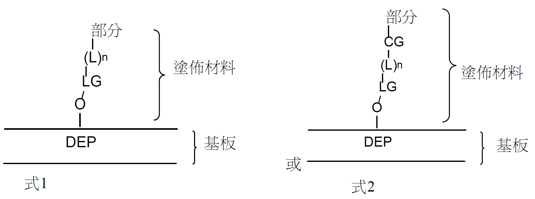
塗佈材料可連接共價DEP組態式或EW組態式基板之表面之氧化物。DEP或EW組態式基板可包含矽、氧化矽、氧化鋁或氧化鉿。氧化物可作為基板之天然化學結構之一部分存在或可如下文所論述引入。The coating material can be attached to the oxide on the surface of the covalent DEP configuration or EW configuration substrate. DEP or EW configurable substrates may contain silicon, silicon oxide, aluminum oxide, or hafnium oxide. The oxide may exist as part of the natural chemical structure of the substrate or may be introduced as discussed below.
塗佈材料可經由連接基團(「LG」)連接至氧化物,該連接基團可為由矽氧烷或膦酸基與氧化物之反應形成之矽烷氧基或膦酸酯基。經組態以提供適用於微流體裝置中之生物學微物件之維持/擴增的有機及/或親水性分子之層之部分可為本文中所描述之部分中之任一者。連接基團LG可直接或間接連接至經組態以提供適用於微流體裝置中之生物學微物件之維持/擴增的有機及/或親水性分子之層之部分。當連接基團LG直接連接至部分時,不存在視情況選用之連接子(「L」)且n為0。當連接基團LG間接連接至部分時,存在連接子L且n為1。連接子L可具有線形部分,其中線形部分之主鏈可包括1至200個選自矽、碳、氮、氧、硫及/或磷原子之任何組合之非氫原子,符合如此項技術中已知的化學鍵結限制。其可間雜有一或多個部分之任何組合,該一或多個部分可選自醚、胺基、羰基、醯胺基及/或膦酸酯基、伸芳基、伸雜芳基或雜環基。在一些實施例中,連接子L之主鏈可包括10至20個原子。在其他實施例中,連接子L之主鏈可包括約5個原子至約200個原子;約10個原子至約80個原子;約10個原子至約50個原子;或約10個原子至約40個原子。在一些實施例中,主鏈原子皆為碳原子。The coating material may be attached to the oxide via a linking group ("LG"), which may be a siloxane or phosphonate group formed by the reaction of a siloxane or phosphonate group with the oxide. The portion configured to provide a layer of organic and/or hydrophilic molecules suitable for the maintenance/amplification of biological micro-objects in a microfluidic device can be any of the portions described herein. The linking group LG can be linked directly or indirectly to a portion of a layer configured to provide a layer of organic and/or hydrophilic molecules suitable for the maintenance/amplification of biological micro-objects in microfluidic devices. When the linking group LG is directly attached to the moiety, there is no optional linker ("L") and n is zero. When the linking group LG is indirectly attached to the moiety, the linker L is present and n is 1. The linker L may have a linear moiety, wherein the backbone of the linear moiety may include 1 to 200 non-hydrogen atoms selected from any combination of silicon, carbon, nitrogen, oxygen, sulfur and/or phosphorus atoms, consistent with those already known in the art. Known chemical bonding limitations. It may be interspersed with any combination of one or more moieties which may be selected from ether, amine, carbonyl, amido and/or phosphonate, arylidene, heteroarylidene or heterocycle base. In some embodiments, the backbone of linker L may include 10 to 20 atoms. In other embodiments, the backbone of linker L can include from about 5 atoms to about 200 atoms; from about 10 atoms to about 80 atoms; from about 10 atoms to about 50 atoms; or from about 10 atoms to about 40 atoms. In some embodiments, the backbone atoms are all carbon atoms.
在一些實施例中,經組態以提供適用於生物學微物件之維持/擴增的有機及/或親水性分子之層之部分可在多步驟過程中添加至基板之表面中且具有式2之結構,如上文所展示。該部分可為上文所描述之部分中之任一者。In some embodiments, portions configured to provide a layer of organic and/or hydrophilic molecules suitable for maintenance/amplification of biological micro-objects can be added to the surface of the substrate in a multi-step process and have
在一些實施例中,偶合基團CG表示來自反應性部分Rx 與反應性配對部分Rpx (亦即,經組態以與反應性部分Rx 反應之部分)之反應之所得基團。舉例而言,一種典型的偶合基團CG可包括甲醯胺基,其為胺基與羧酸之衍生物(諸如經活化之酯、酸氯化物或其類似物)之反應之產物。其他CG可包括伸三唑基、甲醯胺基、硫醯胺基、肟、巰基、二硫化物、醚或烯基,或任何其他可在反應性部分與其相應的反應性配對部分反應時形成之適合的基團。偶合基團CG可位於連接子L之第二端(亦即,靠近經組態以提供適用於微流體裝置中之生物學微物件之維持/擴增的有機及/或親水性分子之層之部分的末端),其可包括如上文所描述之元件之任何組合。在一些其他實施例中,偶合基團CG可間雜至連接子L之主鏈中。當偶合基團CG為伸三唑基時,其可為由克里克偶合反應(Click coupling reaction)產生之產物且可進一步經取代(例如,二苯并環辛烯基稠合之伸三唑基)。In some embodiments, the coupling group CG represents the resulting group from the reaction of a reactive moiety Rx with a reactive counterpart Rpx (ie, a moiety configured to react with a reactive moiety Rx ) . For example, a typical coupling group CG may include a carboxamide group, which is the product of the reaction of an amine group with a derivative of a carboxylic acid, such as an activated ester, acid chloride, or the like. Other CGs can include triazolyl, carboxamido, thioamido, oxime, sulfhydryl, disulfide, ether, or alkenyl groups, or any other that can be formed when a reactive moiety reacts with its corresponding reactive counterpart. suitable group. The coupling group CG can be located at the second end of the linker L (ie, near the layer of organic and/or hydrophilic molecules that are configured to provide suitable maintenance/amplification of biological micro-objects in microfluidic devices. portion), which may include any combination of elements as described above. In some other embodiments, the coupling group CG can be inter-hybridized into the backbone of the linker L. When the coupling group CG is triazolyl, it can be the product resulting from the Click coupling reaction and can be further substituted (eg, dibenzocyclooctenyl fused triazolyl) .
在一些實施例中,使用化學氣相沈積在微流體裝置之內表面上沈積塗佈材料(或表面修飾配位體)。可視情況改良氣相沈積過程,例如藉由預先清潔蓋板110、微流體迴路材料116及/或基板(例如,DEP組態式基板之電極活化基板206之內表面208,或EW組態式基板之支撐結構104之介電層);藉由暴露於溶劑浴;音波處理;或其組合。或者或另外,此類預先清潔可包括在氧電漿清潔劑中處理蓋板110、微流體迴路材料116及/或基板,其可移除各種雜質,同時引入氧化表面(例如,表面處之氧化物,其可如本文中所描述經共價修飾)。或者,液相處理,諸如鹽酸與過氧化氫之混合物或硫酸與過氧化氫之混合物(例如,強清潔性溶液,其可具有約3:1至約7:1的硫酸與過氧化氫之比率)可用於代替氧電漿清潔劑。In some embodiments, chemical vapor deposition is used to deposit the coating material (or surface-modifying ligand) on the inner surface of the microfluidic device. The vapor deposition process can optionally be modified, such as by pre-cleaning the
在一些實施例中,在微流體裝置200經裝配以形成定義微流體迴路120之殼體102之後,使用氣相沈積來塗佈微流體裝置200之內表面。不希望受理論約束,在經完全裝配之微流體迴路120上沈積此類塗佈材料可有利地防止由微流體迴路材料116與電極活化基板206介電層及/或蓋板110之間的弱化鍵引起之分層。在使用兩步驟過程之實施例中,可經由如上文所描述之氣相沈積來引入表面修飾配位體,且隨後引入經組態以提供適用於生物學微物件之維持/擴增的有機及/或親水性分子之層之部分。可藉由使經表面修飾之微流體裝置暴露於含適合的偶合劑之溶液來進行連續反應。In some embodiments, after the
圖2H描繪微流體裝置290之橫截面圖,該微流體裝置具有提供經調節之表面之例示性共價連接之塗佈材料。如所說明,塗佈材料298 (示意性展示)可包含共價結合至基底286 (其可為DEP基板)之內表面294及微流體裝置290之蓋板288之內表面292的密集填充之分子之單層。塗佈材料298可安置於實質上全部內表面294、292上,靠近且面向微流體裝置290之殼體284,在一些實施例中且如上文所論述,包括用於定義微流體裝置290之迴路元件及/或結構之微流體迴路材料之表面(未展示)。在替代性實施例中,塗佈材料298可僅安置於微流體裝置290之一個或一些內表面上。2H depicts a cross-sectional view of a
在圖2H中所展示之實施例中,塗佈材料298可包括有機矽氧烷分子之單層,各分子經由矽烷氧基連接子296共價鍵結至微流體裝置290之內表面292、294。可使用上文所論述之塗佈材料298中之任一者(例如,烷基封端型、氟烷基封端部分、PEG封端部分、聚葡萄糖封端部分或含有用於有機矽烷氧基部分之正或負電荷之末端部分),其中末端部分安置於其面向殼體之末端處(亦即,塗佈材料298之單層之未結合於內表面292、294且靠近殼體284之部分)。In the embodiment shown in FIG. 2H, the
在其他實施例中,用於塗佈微流體裝置290之內表面292、294之塗佈材料298可包括陰離子性、陽離子性或兩性離子性部分或其任何組合。不希望受理論約束,藉由在微流體迴路120之殼體284之內表面處存在陽離子性部分、陰離子性部分及/或兩性離子性部分,塗佈材料298可與水分子形成強氫鍵,使得水合作用之所得水充當避免生物學微物件與非生物分子(例如,基板之矽及/或氧化矽)之相互作用之層(或「遮罩」)。此外,在其中塗佈材料298與塗佈劑結合使用之實施例中,塗佈材料298之陰離子、陽離子及/或兩性離子可與存在於殼體284中之介質180 (例如,塗佈溶液)中的非共價塗佈劑(例如,含蛋白質之溶液)之帶電部分形成離子鍵。In other embodiments, the
在其他實施例中,塗佈材料可在其面向殼體之末端處包含親水性塗佈劑或經化學修飾以在其面向殼體之末端處呈現親水性塗佈劑。在一些實施例中,塗佈材料可包括含有伸烷基醚之聚合物,諸如PEG。在一些實施例中,塗佈材料可包括多醣,諸如聚葡萄糖。與上文所論述之帶電部分(例如,陰離子性、陽離子性及兩性離子性部分)相同,親水性塗佈劑可與水分子形成強氫鍵,使得水合作用之所得水充當避免生物學微物件與非生物分子(例如,基板之矽及/或氧化矽)之相互作用之層(或「遮罩」)。In other embodiments, the coating material may comprise a hydrophilic coating agent at its shell-facing end or be chemically modified to exhibit a hydrophilic coating agent at its shell-facing end. In some embodiments, the coating material may include an alkylene ether-containing polymer, such as PEG. In some embodiments, the coating material may include a polysaccharide, such as polydextrose. As with the charged moieties (eg, anionic, cationic, and zwitterionic moieties) discussed above, hydrophilic coating agents can form strong hydrogen bonds with water molecules, so that the resulting water of hydration acts as a barrier against biological microbes. A layer (or "mask") of interaction of an object with non-biological molecules (eg, silicon and/or silicon oxide of a substrate).
適當的塗層處理及修飾之其他細節可見於2016年4月22日申請之美國申請案第15/135,707號中,且以全文引用之方式併入本文中。Additional details of suitable coating treatments and finishes can be found in US Application No. 15/135,707, filed April 22, 2016, and incorporated herein by reference in its entirety.
用於維持微流體裝置之腔室內的細胞之存活之其他系統組件 . 為了促進細胞群體之生長及/或擴增,可藉由系統之其他組件來提供有助於維持功能細胞的環境條件。舉例而言,此類其他組件可提供營養、細胞生長信號傳導物質、pH值調節、氣體交換、溫度控制,及廢棄產物自細胞之移除。 Other system components for maintaining the survival of cells within the chambers of the microfluidic device . To promote growth and/or expansion of cell populations, environmental conditions that help maintain functional cells can be provided by other components of the system. For example, such other components can provide nutrition, cell growth signaling substances, pH regulation, gas exchange, temperature control, and removal of waste products from cells.
分析由生物學微物件分泌之分析物 . 在一些實施例中,本發明提供用於定量腔室中存在之生物分子之方法、系統及裝置。在一些實施例中,生物分子為生物細胞分泌之分析物或任何其他能夠產生分泌型分析物之生物學微生物體。 Analysis of analytes secreted by biological micro-objects . In some embodiments, the present invention provides methods, systems and devices for quantifying biomolecules present in a chamber. In some embodiments, the biomolecule is an analyte secreted by a biological cell or any other biological microorganism capable of producing a secreted analyte.
在生物生產工業中,一個嚴重的問題係在使用當前可用的儀器及工作流程時,鑑別具有所需生產量及生長習慣之純系群體之費用、時間及困難。舉例而言,產生新的抗體生產線可耗費好幾個月的工作以及在人員、裝備及材料方面的數百萬美元之成本。如本文中所描述,在擴增群體中在極早期(諸如在接種個別奠基細胞之後第3、4、5、6或7天),在微流體裝置內篩選及鑑別有前景的純系之能力可提供顯著的時間及成本優勢。申請人已發現,如本文中所描述之奈米流體環境,特定言之,基於腔室之奈米流體環境提供純系群體彼此之間的例示性隔離,實現自各個純系群體獲得分析結果而不存在來自位於微流體裝置內之其他純系群體之污染之能力。亦發現,在更典型的大規模擴增(例如,搖瓶等)之情況下,用於使用本文中所描述之方法來測定分泌型分析物之相對或絕對量之分析(甚至在純系擴增之早期進行時)可與所需的分泌型分析物之產量相關。此外,在此類早期篩選個別純系之能力亦可實現滿足特定的生長率及/或更穩定的生產之需求之所需純系(例如,高生產性純系,其對培養環境中之材料(諸如代謝廢棄產物或耗竭型營養)之含量之抗性更高)之鑑別。A serious problem in the bioproduction industry is the cost, time, and difficulty of identifying a pure line population with the desired productivity and growth habits using currently available instruments and workflows. For example, generating a new antibody production line can take months of work and cost millions of dollars in personnel, equipment, and materials. As described herein, the ability to screen and identify promising clones within a microfluidic device at a very early stage in an expanded population (such as at 3, 4, 5, 6, or 7 days after seeding individual founder cells) Offers significant time and cost advantages. Applicants have discovered that nanofluidic environments as described herein, in particular, chamber-based nanofluidic environments provide exemplary isolation of clone populations from each other, enabling analytical results to be obtained from individual clone populations without the presence of The ability to contaminate from other pure populations located within the microfluidic device. It was also found that in the case of more typical large-scale amplifications (eg, shake flasks, etc.), assays for determining relative or absolute amounts of secreted analytes using the methods described herein (even in clonal amplifications) performed earlier) can be correlated with the yield of the desired secreted analyte. In addition, the ability to screen individual clones at such an early stage may also enable desired clones to meet specific growth rates and/or requirements for more stable production (eg, highly productive clones that are sensitive to materials in the culture environment, such as metabolic Identification of waste products or depleted nutrients) with higher levels of resistance.
申請人發現之另一優點可在不使用過度的資源之情況下進行作為純系群體之潛在奠基細胞之複數個細胞之更全面的研究,因為本文中所描述之奈米流體腔室(例如,腔室)允許在極其小的體積中同時進行數千個個別奠基細胞之同時生長/分析。Another advantage discovered by Applicants is that a more comprehensive study of multiple cells as potential founder cells of a clonal population can be performed without using undue resources, because the nanofluidic chambers described herein (eg, chambers) chamber) allows simultaneous growth/analysis of thousands of individual founder cells in extremely small volumes.
此外,本文中所描述之奈米流體環境允許檢驗特定條件對細胞之作用及來自重複分析之回饋。舉例而言,可使用與細胞之分泌產物(本文中之方法中之分析物)之大規模生產更密切相關之條件及材料(諸如培養基)來尋找及表徵最適於進一步檢驗之純系。在另一實例中,可以可再現性更高之方式來檢驗用於B細胞抗體刺激之不同刺激方案,且可進行分析以更具可比性地評估一種方案相對於另一種方案之優勢。In addition, the nanofluidic environments described herein allow examining the effects of specific conditions on cells and feedback from repeated analyses. For example, conditions and materials (such as culture media) that are more closely related to the large-scale production of secreted products from cells (analytes in the methods herein) can be used to find and characterize the most suitable clones for further testing. In another example, different stimulation regimens for B cell antibody stimulation can be tested in a more reproducible manner, and analyses can be performed to more comparable assess the advantages of one regimen over another.
使用擴散概況進行偵測及定量 . 如本文中所描述,可使用結合於分泌型分析物之報導分子來對生物學微物件之分泌型分析物之量進行定量。報導分子包括結合待定量之分泌型分析物之結合組分及用於偵測報導分子之量之信號組分。與結合狀態相比(例如,結合於分泌型分析物之一或多個分子),報導分子在其未結合狀態下(例如,未結合於分泌型分析物)具有更高的擴散率。在一些實施例中,未結合及結合之報導分子之間的擴散率之差將取決於與報導分子結合之分泌型分析物分子之大小。在一些實施例中,報導分子可以減緩擴散率之構形與分泌型分析物結合。舉例而言,報導分子可以其中分泌型分析物部分因其構形而聚集且緩慢擴散之構形結合分泌型分析物之多個複本。本文中所描述之方法利用報導分子(未結合)與結合之報導分子:分析物複合物(RMSA)之間的擴散率之差來對分泌型分析物之量進行定量。 Detection and Quantification Using Diffusion Profiles . As described herein, the amount of secreted analyte in biological micro-objects can be quantified using reporter molecules that bind to secreted analytes. The reporter molecule includes a binding component that binds the secreted analyte to be quantified and a signal component that is used to detect the amount of the reporter molecule. The reporter molecule has a higher diffusivity in its unbound state (eg, not bound to the secreted analyte) than in the bound state (eg, bound to one or more molecules of the secreted analyte). In some embodiments, the difference in diffusivity between unbound and bound reporter molecules will depend on the size of the secreted analyte molecule bound to the reporter molecule. In some embodiments, the reporter molecule can bind to the secreted analyte in a configuration that slows the diffusion rate. For example, a reporter molecule can bind multiple copies of a secreted analyte in a configuration in which the secreted analyte moiety aggregates due to its configuration and diffuses slowly. The methods described herein utilize the difference in diffusivity between the reporter (unbound) and the bound reporter:analyte complex (RMSA) to quantify the amount of secreted analyte.
微流體通道中之在流動條件下之擴散分析 .
圖4A-4C說明根據本發明之一些實施例之分析。在圖4A中,藉由使流242內之含有一定濃度之報導分子412之流體流入微流體裝置400之通道122來將各自具有可偵測標記之報導分子412引入微流體通道122。腔室424、426、428各自以流體方式連接至微流體通道122,含有各種數目之分泌生物學分析物410之細胞402、404、406。腔室424、426、428中之每一者包括連接區域436及隔離區域440 (僅為了清楚起見,腔室424為唯一如此標記之欄)。連接區域436及隔離區域440具有如上文所描述之特性,且限制被引入通道122之材料之接觸(例如,在隔離區域440內,在通道122內流動之材料可僅藉由擴散,而非藉由直接流入隔離區域來進入隔離區域)。在圖4A中所說明的時間點時,分泌型分析物410之分子靠近細胞。 Diffusion analysis under flow conditions in a microfluidic channel . Figures 4A-4C illustrate analysis according to some embodiments of the invention. In Figure 4A,
圖4B說明在稍後時間點時的與圖4A中相同之微流體裝置之區域。報導分子412可在通道122及腔室424、426、428內快速擴散,使得報導分子412之濃度在通道122與腔室424、426、428之內部之間平衡。如圖4B中所說明,報導分子412達到在腔室424、426、428內實質上均一的穩態濃度。用不含報導分子412之介質之流242置換含有報導分子412之介質之流242,且通道122不含大量報導分子。Figure 4B illustrates the same region of the microfluidic device as in Figure 4A at a later point in time. The
隨著各腔室424、426、428內之報導分子412與分泌型分析物410之分子接觸,報導分子412可結合於分析物410,形成報導分子:分析物複合物414,且提供與分泌型分析物410之量相關的局部可偵測信號。隨著流242繼續行進,報導分子擴散出腔室,進入通道122且離開微流體裝置。然而,如圖4B中所示,歸因於報導分子:分析物複合物410之較大分子量(及有效大小),其擴散比未結合之報導分子412慢且有差別的是,其擴散速度慢於離開腔室424、426、428之速度。As the
圖4C說明在稍後時間點時的與圖4A及4B中相同的微流體裝置之區域,此時分泌型分析物410及報導分子:分析物複合物414自分泌型分析物410之來源(例如,細胞402、404、406)擴散至通道122。流242在通道122內繼續行進,藉此允許報導分子412比報導分子:分析物複合物410更快地擴散出各腔室424、426、428。Figure 4C illustrates the same region of the microfluidic device as in Figures 4A and 4B at a later point in time when the secreted
報導分子:分析物複合物更緩慢地擴散,因為分泌型分析物分子410與報導分子412相比可能具有更大的分子量(及在溶液中之相關有效大小)。在其中分泌型分析物為抗體且報導分子為肽或適體之實施例中,分子量之差異係顯著的。在任何情況下,結合之報導分子:分析物複合物414之重量(且因此,大小)大於未結合之報導分子412之重量且因此,報導分子:分析物複合物414可比未結合之報導分子412更緩慢地擴散,提供與由未結合之報導分子412提供之均一信號不同的擴散概況及相關可偵測信號。此外,生物學微物件502、504、506繼續分泌分析物410,提供更多的用於與仍安置於腔室524、526、528內之報導分子412結合之目標。可選擇其中正在擴散或已擴散出腔室之未結合之報導分子之百分比超過閾值之時間點,允許來自各腔室424、426、428內之實質上或主要僅報導分子:分析物複合物414之可偵測信號之成像。在一些實施例中,當擴散出腔室之未結合之報導分子412之量為約10%、15%、20%、25%、30%、35%、40%、45%、50%、55%、60%、65%、70%、75%、80%、85%、90%或由兩個前述值定義之任何範圍時,獲取分析影像。或者或另外,在一些實施例中,當擴散出腔室之未結合之報導分子412之量比擴散出腔室之結合之報導分子:分析物複合物414之量大約1.25倍、1.5倍、2.0倍、2.5倍、3.0倍、3.5倍、4.0倍、4.5倍、5.0倍、7.5倍、10倍、25倍、50倍或100倍時,獲取分析影像。Reporter:Analyte complexes diffuse more slowly because secreted
在分析影像中獲得之可偵測信號可與腔室中之生物學微物件之數目成比例。腔室424說明為含有6個生物學微物件,腔室426說明為含有4個生物學微物件且腔室428說明為含有2個生物學微物件且在一些實施例中,來自相應腔室之分析信號可與此等細胞之數目成比例。在一些實施例中,分析物之分泌可取決於分析信號獲取時的細胞循環狀態,且來自複數個腔室中之每一者之信號可能實質上不與各腔室內之細胞之數目成比例。此外,如圖4C中所說明,儘管所有細胞402、404、406皆分泌分析物410,但不同細胞群體(例如,不同純系)可以不同速率分泌生物學分析物410。因此,各腔室之所產生之分析物410之量(及自報導分子:分析物複合物414偵測之擴散概況信號之所得強度)可能不同,甚至在針對各腔室中存在之細胞402、404、406之數目標準化時。可在此時間段期間獲得一或多個分析影像,其可用於表徵經成像之腔室424、426、428內的分泌型分析物410之量。用於實現所產生之分泌型分析物410之量之相對或絕對定量的分析之說明提供於下文中。The detectable signal obtained in analyzing the images can be proportional to the number of biological micro-objects in the chamber.
如上所陳述,因為分泌型分析物分子可能具有比報導分子更大的分子量(及在溶液中之相關有效大小),所以報導分子:分泌型分析物(RMSA)複合物更緩慢地擴散。在其中分泌型分析物為抗體且報導分子為肽或適體之實施例中,分子量之差異係顯著的。在任何情況下,結合之RSMA複合物之重量(且因此,大小)大於未結合之報導分子之重量且因此,RSMA複合物可比未結合之報導分子更緩慢地擴散,提供與由未結合之報導分子提供之均一信號不同的擴散概況及相關可偵測信號。As stated above, the reporter:secreted analyte (RMSA) complex diffuses more slowly because the secreted analyte molecule may have a larger molecular weight (and associated effective size in solution) than the reporter molecule. In embodiments where the secreted analyte is an antibody and the reporter molecule is a peptide or aptamer, the difference in molecular weight is significant. In any event, the weight (and thus, size) of the bound RSMA complexes is greater than the weight of the unbound reporter molecules and, therefore, the RSMA complexes can diffuse more slowly than the unbound reporter molecules, providing a contrast between the unbound reporter molecules and the The molecules provide a uniform signal with different diffusion profiles and associated detectable signals.
未結合之報導子與RMSA複合物之間的分子量差異之重要之處在於可影響本文中所論述之一些分析方法對涉及產生小分子量分子(小分子量分泌型分析物)之工作流程之相容性。因為擴散率天然地為相關組分之重量/大小之結果且不同的擴散概況允許收集有價值的可偵測信號,在結合由細胞分泌之小分子量分子時,如何減緩分析試劑之擴散似乎並不明顯。因此,此可引起結合之螢光物質與游離螢光物質之間的擴散率之不可辨別的差異,且因此似乎不存在用於獲得必要的擴散概況以收集必要的可偵測信號之明確途徑。藉由克服此問題,本文中所揭示之各種實施例可相對於例如小型代謝物、生物燃料或其他相關小分子之分泌來實施。The molecular weight difference between the unbound reporter and the RMSA complex is important in that it can affect the compatibility of some of the analytical methods discussed herein for workflows involving the production of small molecular weight molecules (small molecular weight secreted analytes). . Since diffusivity is naturally a consequence of the weight/size of the relevant components and different diffusion profiles allow the collection of valuable detectable signals, how to slow down the diffusion of analytical reagents when bound to small molecular weight molecules secreted by cells does not seem to matter. obvious. Thus, this can lead to an indiscernible difference in diffusivity between bound and free fluorophores, and thus there does not appear to be a clear route for obtaining the necessary diffusion profile to collect the necessary detectable signal. By overcoming this problem, the various embodiments disclosed herein can be implemented with respect to, for example, the secretion of small metabolites, biofuels, or other related small molecules.
可實現量測小分子之產量,例如藉由顛倒根據各種實施例之細胞株發育分析,其中較亮的螢光腔室將不指示最高生產細胞株,而實際上指示較弱的生產細胞株。在一個實例中,已知結合於小分子目標之分子(例如,大型分子量蛋白質或蛋白質複合物,稱為「錨」)將首先在晶片外與相關目標之螢光版本結合。此螢光複合物(錨+螢光目標)將在整個晶片內平衡,包括含有細胞之腔室內,該等細胞可分泌目標之非螢光版本。在存在此等未經標記之目標之情況下,結合動力學將驅動經標記之目標與腔室內濃度高得多的未經標記之目標之交換。在將通道沖洗乾淨一段時間之後,未由錨結合之螢光目標將自腔室快速擴散。因此,當在此沖洗之後讀取螢光水準時,所觀測之較暗的腔室將等同於分泌更多的小分子量目標之腔室。Measuring the production of small molecules can be accomplished, for example, by inverting the cell line development assay according to various embodiments, where brighter fluorescent chambers will not indicate the highest producer cell line, but in fact a weaker producer cell line. In one example, molecules known to bind to small molecular targets (eg, large molecular weight proteins or protein complexes, referred to as "anchors") will first bind off-chip to fluorescent versions of the relevant targets. This fluorescent complex (anchor + fluorescent target) will equilibrate throughout the wafer, including the chamber containing cells that secrete non-fluorescent versions of the target. In the presence of such unlabeled targets, the binding kinetics will drive the exchange of labeled targets with much higher concentrations of unlabeled targets within the chamber. After flushing the channel for a period of time, the fluorescent targets not bound by the anchor will diffuse rapidly from the chamber. Thus, when the fluorescence level is read after this wash, the darker chambers observed will be equivalent to chambers secreting more small molecular weight target.
圖33A-C說明根據各種實施例之此方法之實例。在圖33A中,將高MW錨蛋白質3710 (例如,抗體)及結合之螢光分子3720 (經標記之目標)一起引入含有細胞3760及經分泌之未經標記之目標3730之腔室3750。在圖33B中,結合動力學驅動經標記之目標3720與未經標記之目標3730之交換。舉例而言,假設需要尋找產生最高量之FcIII肽之細胞。為此,鑒於上述內容,可添加預先結合於錨定晶片之經標記之FcIII。在將此經標記之目標引入腔室之後,隨時間推移,將發生腔室中之由細胞分泌之未經標記之FcIII與預先平衡至錨上之經標記之FcIII之間的交換。最終,在圖33C中,完成交換且可沖洗通道以允許未結合之螢光目標擴散出欄。由此,可使用標準影像擷取及分析(如本文中所論述)來觀測螢光水準。然而,與尋求更亮的腔室(如指示高分泌量)相反,因為移除未結合之螢光目標,較暗的腔室分泌更多的小分子目標。33A-C illustrate an example of this method according to various embodiments. In Figure 33A, a high MW anchor protein 3710 (eg, an antibody) is introduced together with a bound fluorescent molecule 3720 (labeled target) into a
微流體通道中之在非流動條件下之擴散分析
. 圖5A至5C說明根據本發明之一個實施例之分析。在圖5A中,藉由使含有一定濃度之報導分子412之流體流入通道122來將各自具有可偵測標記之報導分子412引入微流體裝置500之微流體通道122。圖5A亦展示以流體方式連接至微流體通道122之腔室524、526、528,其含有各種數目之分泌生物學分析物410之細胞502、504、506。腔室524、526、528中之每一者包括連接區域536及隔離區域540 (僅為了清楚起見,腔室524為唯一的經標記之欄)。連接區域536及隔離區域540具有如上文所描述之特性,且限制被引入通道122之材料之接觸(例如,在隔離區域540內,在通道122內流動之材料可僅藉由擴散,而非藉由直接流入隔離區域來進入隔離區域)。在圖5A中所說明的時間點時,分泌型分析物410之分子靠近細胞。 Diffusion analysis under non-flow conditions in a microfluidic channel . Figures 5A-5C illustrate an analysis according to one embodiment of the present invention. In FIG. 5A ,
圖5B說明在稍後時間點時的與圖5A中相同之微流體裝置之區域。報導分子412可在通道122及腔室524、526、528內快速擴散,使得報導分子412之濃度在通道122與腔室524、526、528之內部之間平衡。如圖5B中所說明,報導分子412達到穩態濃度平衡,使得未結合之報導分子412之濃度可在腔室524、526、528及通道122中為實質上均一的。當報導分子412之濃度平衡至腔室524、526、528中時,通道中之流停止。隨著報導分子412與分泌型分析物410之分子接觸,報導分子412可結合於分析物410,形成報導分子:分析物複合物414,且提供與分泌型分析物410之量相關的局部可偵測信號。Figure 5B illustrates the same region of the microfluidic device as in Figure 5A at a later point in time. The
圖5C說明在稍後時間點時的與圖5A及5B中相同的微流體裝置之區域,此時分泌型分析物410及報導分子:分析物複合物414自分泌型分析物410之來源(例如,細胞502、504、506)擴散至通道122。在此時間點時,通道122中不存在流。Figure 5C illustrates the same region of the microfluidic device as in Figures 5A and 5B at a later time point when the secreted
如上所述,與報導分子412相比,分泌型分析物分子410可具有更大的分子量(及溶液中之相關有效大小)。因此,報導分子:分析物複合物414可比未結合之報導分子412更緩慢地擴散,提供與由未結合之報導分子412提供之均一信號不同的擴散概況及相關可偵測信號。此外,生物學微物件502、504、506繼續分泌分析物410,提供更多的用於與仍安置於腔室524、526、528內之報導分子412結合之目標。As discussed above, the secreted
擴散概況及/或相關信號可與腔室中之生物學微物件之數目成比例。腔室524說明為含有6個生物學微物件,腔室526說明為含有4個生物學微物件且腔室528說明為含有2個生物學微物件。然而,在一些其他實施例中,相應腔室524、526、528中之細胞502、504、506可以大致相同的速率分泌分析物410,且來自報導分子:分析物複合物414之所偵測之信號之所得強度可與各腔室中存在之細胞502、504、506之數目成比例。然而,分析物之分泌可取決於分析信號獲取時之細胞循環狀態。此外,如圖5C中所說明,儘管細胞502、504、506皆分泌分析物,但不同對細胞群體(例如,不同的純系)可以不同速率分泌生物學分析物410。因此,各腔室之所產生之分析物410之量(及自報導分子:分析物複合物414偵測之擴散概況信號之所得強度)可能不同,甚至在針對各腔室中存在之細胞502、504、506之數目標準化時。可在此時間段期間獲得一或多個分析影像,其可用於表徵經成像之腔室524、526、528內的分泌型分析物410之量。用於實現所產生之分泌型分析物410之量之相對或絕對定量的分析之說明提供於下文中。The diffusion profile and/or associated signal can be proportional to the number of biological micro-objects in the chamber.
分泌型分析物.
由生物學微物件分泌之分析物可為蛋白質、醣、核酸、具有小於3 Kd之分子量之有機分子、囊泡、病毒及其任何組合。分泌型分析物可為經天然表現之分析物(例如,原生地表現)或可為經生物工程改造之分析物(例如,由基因插入、缺失、修飾產生之產物及其類似物)。核酸類分泌型分析物可為核糖核酸或脫氧核糖核酸,可包括天然或非天然核苷酸。病毒類分泌型分析物可為病毒粒子、載體或噬菌體。醣類分泌型分析物可為單醣、二醣或多醣。醣之非限制性實例可包括葡萄糖、海藻糖、甘露糖、阿拉伯糖(arabinose)、果糖、核糖、三仙膠或聚葡萄胺糖。所分泌之小型有機分子可包括(但不限於)生物燃料、油、聚合物或藥劑,諸如巨環內酯抗生素。蛋白質類分泌型分析物可為抗體或抗體之片段。蛋白質類分泌型分析物可為血液蛋白質,諸如白蛋白、球蛋白(例如,α2-巨球蛋白、γ球蛋白、β-2微球蛋白、結合球蛋白)、補體蛋白(例如,組分3或4)、轉鐵蛋白、凝血酶原、α1抗胰蛋白酶及其類似物;激素,諸如胰島素、升糖素、生長抑素、生長激素、生長因子(例如,FGF、HGF、NGF、EGF、PDGF、TGF、紅細胞生成素、IGF、TNF)、促卵泡激素、促黃體生成激素、瘦素及其類似物;纖維性蛋白質,諸如絲或細胞外基質蛋白(例如,纖維結合蛋白、層黏連蛋白、膠原蛋白、彈性蛋白、玻璃連結蛋白、腱生蛋白、多功能蛋白聚糖、骨骼唾液蛋白);酶,諸如金屬蛋白酶(例如,基質金屬蛋白酶(MMP))或其他類型之蛋白酶(例如,絲胺酸蛋白酶、半胱胺酸蛋白酶、蘇胺酸蛋白酶、天冬胺酸蛋白酶、麩胺酸蛋白酶、天冬醯胺肽解離酶)、澱粉酶、纖維素酶、過氧化氫酶、果膠酶及其類似物;細菌、酵母或原蟲蛋白質;植物蛋白質;o型或病毒蛋白,諸如衣殼或包膜蛋白。蛋白質類分泌型分析物可為抗體、抗體之片段、酶(包括(但不限於)蛋白水解酶)、經工程改造(通常,細胞內蛋白質)蛋白質,如白蛋白,及/或結構蛋白,包括(但不限於)蠶絲或蜘蛛絲。此清單不具有限制性且可藉由該等方法評估任何可經工程改造以進行分泌之蛋白質。分泌型分析物可為抗體-藥物結合物。可具有蛋白質、醣、核酸、具有小於3 Kd之分子量之有機分子及/或病毒之組合的分泌型分析物之非限制性實例可包括蛋白聚糖或醣蛋白。Secreted Analytes . Analytes secreted by biological micro-objects can be proteins, sugars, nucleic acids, organic molecules with molecular weights less than 3 Kd, vesicles, viruses, and any combination thereof. Secreted analytes can be naturally expressed analytes (eg, natively expressed) or can be bioengineered analytes (eg, products resulting from gene insertions, deletions, modifications, and the like). Nucleic acid-based secretory analytes can be ribonucleic acid or deoxyribonucleic acid, and can include natural or non-natural nucleotides. Viral secretory analytes can be virions, vectors, or phages. Saccharide secretory analytes may be monosaccharides, disaccharides or polysaccharides. Non-limiting examples of sugars may include glucose, trehalose, mannose, arabinose, fructose, ribose, sucrose, or polyglucosamine. Secreted small organic molecules can include, but are not limited to, biofuels, oils, polymers, or pharmaceuticals, such as macrolide antibiotics. The proteinaceous secreted analyte can be an antibody or a fragment of an antibody. Proteinaceous secreted analytes can be blood proteins such as albumin, globulins (eg, alpha 2-macroglobulin, gamma globulin, beta-2 microglobulin, binding globulin), complement proteins (eg,
報導分子及其特徵 . 報導分子可包括經設計以結合分泌型分析物之結合組分且亦可包含可偵測標記。結合組分可為任何適合的經組態以結合分泌型分析物之結合搭配物。結合組分可為蛋白質、肽、核酸或具有小於3 Kd之分子量之小型有機分子。舉例而言,結合組分可為特異性結合另一核酸序列之核酸序列或特異性結合蛋白質之肽(例如,識別特異性抗體之抗原決定基)。在一些實施例中,結合組分可非特異性結合生物學微物件之分泌型分析物家族。舉例而言,結合組分可為特異性結合於IgG域之肽或結合於存在於核酸序列家族中之域之核酸。在一些實施例中,報導分子可為多價的,包含超過一個結合組分以結合分泌型分析物之超過一個複本或分泌型分析物家族之超過一個成員。為了易於論述,如本文中所使用之術語分泌型分析物可指特定的分泌型分析物分子或分泌型分析物家族。因此,RMSA複合物之化學計量可變化。舉例而言,結合分泌型分析物之一個複本之報導分子可以1:1化學計量具有RMSA複合物。或者,RMSA複合物之報導分子:分泌型分析物之化學計量可為2:1、3:1、4:1、2:2、4:2等。報導分子可具有任何適合的分子量,只要表觀「大小」(如由報導分子:分析物複合物之擴散特徵定義,該擴散特徵係取決於分子量)充分「大於」報導分子本身以觀測未結合之報導分子與RMSA複合物之間的不同擴散即可。報導分子之分子量可為分泌型分析物之分子量之約10%、20%、30%、40%、50%、60%、70%、80%、90%或相同。在一些實施例中,報導分子之分子量小於分泌型分析物之分子量之約50%、40%、30%、20%、10%。RMSA複合物之分子量可比報導分子之分子量大至少2倍、4倍、10倍、20倍、30倍、40倍、50倍或其間的任何數目。RMSA複合物之分子量可比未結合之報導分子之分子量大2倍、4倍或50倍。 Reporter Molecules and Characteristics thereof . Reporter molecules may include binding components designed to bind secreted analytes and may also include detectable labels. The binding component can be any suitable binding partner configured to bind the secreted analyte. The binding components can be proteins, peptides, nucleic acids or small organic molecules with molecular weights less than 3 Kd. For example, a binding component can be a nucleic acid sequence that specifically binds another nucleic acid sequence or a peptide that specifically binds a protein (eg, an epitope that recognizes a specific antibody). In some embodiments, the binding component can non-specifically bind to a family of secreted analytes of biological micro-objects. For example, the binding component can be a peptide that specifically binds to an IgG domain or a nucleic acid that binds to a domain present in a family of nucleic acid sequences. In some embodiments, the reporter molecule may be multivalent, comprising more than one binding component to bind more than one replica of a secreted analyte or more than one member of a family of secreted analytes. For ease of discussion, the term secreted analyte as used herein may refer to a particular secreted analyte molecule or family of secreted analytes. Thus, the stoichiometry of the RMSA complex can vary. For example, a reporter molecule that binds one replica of a secreted analyte can have a RMSA complex in a 1:1 stoichiometry. Alternatively, the reporter molecule:secreted analyte stoichiometry of the RMSA complex may be 2:1, 3:1, 4:1, 2:2, 4:2, etc. The reporter molecule can have any suitable molecular weight, so long as the apparent "size" (as defined by the diffusion characteristics of the reporter:analyte complex, which depends on molecular weight) is sufficiently "larger" than the reporter molecule itself to observe unbound molecules. Differential diffusion between the reporter molecule and the RMSA complex is sufficient. The molecular weight of the reporter molecule can be about 10%, 20%, 30%, 40%, 50%, 60%, 70%, 80%, 90% or the same as the molecular weight of the secreted analyte. In some embodiments, the molecular weight of the reporter molecule is less than about 50%, 40%, 30%, 20%, 10% of the molecular weight of the secreted analyte. The molecular weight of the RMSA complex can be at least 2-fold, 4-fold, 10-fold, 20-fold, 30-fold, 40-fold, 50-fold, or any number in between, greater than the molecular weight of the reporter molecule. The molecular weight of the RMSA complex can be 2-fold, 4-fold or 50-fold greater than the molecular weight of the unbound reporter molecule.
一種分泌型分析物:抗體之報導分子 . 適於結合於抗體之報導分子包括經組態以結合IgG之區域之蛋白質、肽及適體。適於在報導分子內使用以偵測抗體之結合組分之非限制性清單展示於表1中。 A secreted analyte: a reporter molecule for an antibody. Reporter molecules suitable for binding to antibodies include proteins, peptides and aptamers configured to bind to regions of IgG. A non-limiting list of binding components suitable for use within reporter molecules to detect antibodies is shown in Table 1.
表
CPD 1-14中之任一者可用於本文中所描述之分析中。以上所列舉之一些CPD為小型肽,已知其結合於IgG之Fc域(關於CPD 4及7-14,參見DeLano WL等人, (2000), Science 287:1279-1283,及美國專利案第7608681B2號,其揭示內容各自以全文引用之方式併入本文中)。Any of CPDs 1-14 can be used in the assays described herein. Some of the CPDs listed above are small peptides known to bind to the Fc domain of IgG (for
CPD 3具有Asp Ser Ala Trp His Leu Gly Glu Leu Val Trp Cys Thr (SEQ ID NO:9)之結構。
CPD4具有Asp Cys Ala Trp His Leu Gly Glu Leu Val Trp Cys Thr (SEQ ID NO:10)之結構。CPD4 has the structure of Asp Cys Ala Trp His Leu Gly Glu Leu Val Trp Cys Thr (SEQ ID NO: 10).
CPD 7具有Xaa1
-Xaa2
-Xaa3
-Xaa4
-Xaa5
-Xaa6
-Xaa7
-Xaa8
-Xaa9
-Xaa10
-Xaa11
-Leu-Val-Trp-Cys-Xaa16
-Xaa17
-Xaa18
-Xaa19
-Xaa20
(SEQ ID NO:1)之結構,其中:Xaa1
為任何胺基酸或不存在;Xaa2
為任何胺基酸或不存在;Xaa3
為任何胺基酸或不存在;Xaa4
為任何胺基酸或不存在;Xaa5
為Cys或Ser;Xaa6
為任何胺基酸;Xaa7
為任何胺基酸;Xaa8
為任何胺基酸;Xaa9
為任何胺基酸;Xaa10
為任何胺基酸;Xaa11
為任何胺基酸;Xaa16
為任何胺基酸或不存在;Xaa17
為任何胺基酸或不存在;Xaa18
為任何胺基酸或不存在;Xaa19
為任何胺基酸或不存在;且Xaa20
為任何胺基酸或不存在。
CPD 8具有Xaa1
-Xaa2
-Xaa3
-Xaa4
-Xaa5
-Xaa6
-Xaa7
-Xaa8
-Xaa9
-Gly-Glu-Leu-Val-Trp-Cys-Xaa16
-Xaa17
-Xaa18
-Xaa19
-Xaa20
(SEQ ID NO:2)之結構,其中:Xaa1
為任何胺基酸或不存在;Xaa2
為任何胺基酸或不存在;Xaa3
為任何胺基酸或不存在;Xaa4
為任何胺基酸或不存在;Xaa5
為Cys或Ser;Xaa6
為任何胺基酸;Xaa7
為任何胺基酸;Xaa8
為任何胺基酸;Xaa9
為任何胺基酸;Xaa16
為任何胺基酸或不存在;Xaa17
為任何胺基酸或不存在;Xaa18
為任何胺基酸或不存在;Xaa19
為任何胺基酸或不存在;且Xaa20
為任何胺基酸或不存在。
CPD 9具有Xaa1 -Xaa2 -Xaa3 -Xaa4 -Xaa5 -Xaa6 -Xaa7 -Xaa8 -Xaa9 -Gly-Glu-Leu-Val-Trp-Cys-Xaa16 -Xaa17 -Xaa18 -Xaa19 -Xaa20 (SEQ ID NO:3)之結構,其中:Xaa1 為任何胺基酸或不存在;Xaa2 為任何胺基酸或不存在;Xaa3 為任何胺基酸或不存在;Xaa4 為任何胺基酸或不存在;Xaa5 為Cys或Ser;Xaa6 為Ala、Ser或Thr;Xaa7 為Trp或Tyr;Xaa8 為His或Trp;Xaa9 為Leu或Met;Xaa16 為任何胺基酸或不存在;Xaa17 為任何胺基酸或不存在;Xaa18 為任何胺基酸或不存在;Xaa19 為任何胺基酸或不存在;且Xaa20 為任何胺基酸或不存在。CPD 9 has Xaa 1 -Xaa 2 -Xaa 3 -Xaa 4 -Xaa 5 -Xaa 6 -Xaa 7 -Xaa 8 -Xaa 9 -Gly-Glu-Leu-Val-Trp-Cys-Xaa 16 -Xaa 17 -Xaa 18 - Structure of Xaa 19 -Xaa 20 (SEQ ID NO: 3), wherein: Xaa 1 is any amino acid or absent; Xaa 2 is any amino acid or absent; Xaa 3 is any amino acid or absent Xaa 4 is any amino acid or absent; Xaa 5 is Cys or Ser; Xaa 6 is Ala, Ser or Thr; Xaa 7 is Trp or Tyr; Xaa 8 is His or Trp; Xaa 9 is Leu or Met; Xaa 16 is any amino acid or absent; Xaa 17 is any amino acid or absent; Xaa 18 is any amino acid or absent; Xaa 19 is any amino acid or absent; and Xaa 20 is any amino acid Acid or not present.
CPD 10具有Xaa1 -Xaa2 -Xaa3 -Xaa4 -Xaa5 -Xaa6 -Xaa7 -Xaa8 -Xaa9 -Gly-Glu-Leu-Val-Trp-Cys-Xaa16 -Xaa17 -Xaa18 -Xaa19 -Xaa20 (SEQ ID NO:4)之結構,其中:Xaa1 為任何胺基酸或不存在;Xaa2 為任何胺基酸或不存在;Xaa3 為任何胺基酸或不存在;Xaa4 為Ser、Arg或Asp;Xaa5 為Cys或Ser;Xaa6 為Ala、Ser或Thr;Xaa7 為Trp或Tyr;Xaa8 為His或Trp;Xaa9 為Leu或Met;Xaa16 為Glu、Ser、Thr或Val;Xaa17 為任何胺基酸或不存在;Xaa18 為任何胺基酸或不存在;Xaa19 為任何胺基酸或不存在;且Xaa20 為任何胺基酸或不存在。CPD 10 has Xaa1 - Xaa2 -Xaa3 - Xaa4- Xaa5 -Xaa6- Xaa7 -Xaa8- Xaa9 -Gly-Glu-Leu-Val-Trp-Cys- Xaa16 - Xaa17 - Xaa18 - Structure of Xaa 19 -Xaa 20 (SEQ ID NO: 4), wherein: Xaa 1 is any amino acid or absent; Xaa 2 is any amino acid or absent; Xaa 3 is any amino acid or absent Xaa 4 is Ser, Arg or Asp; Xaa 5 is Cys or Ser; Xaa 6 is Ala, Ser or Thr; Xaa 7 is Trp or Tyr; Xaa 8 is His or Trp; Xaa 9 is Leu or Met; Xaa 16 is Glu, Ser, Thr or Val; Xaa 17 is any amino acid or absent; Xaa 18 is any amino acid or absent; Xaa 19 is any amino acid or absent; and Xaa 20 is any amino acid or does not exist.
CPD 11具有Xaa1 -Xaa2 -Xaa3 -Xaa4 -Xaa5 -Xaa6 - Xaa7 -Xaa8 -Leu-Val-Trp-Cys-Xaa13 (SEQ ID NO:5)之結構,其中:Xaa1 為任何胺基酸或不存在;Xaa2 為Cys或Ser;Xaa3 為任何胺基酸;Xaa4 為任何胺基酸;Xaa5 為任何胺基酸;Xaa6 為任何胺基酸;Xaa7 為任何胺基酸;Xaa8 為任何胺基酸;且Xaa13 為任何胺基酸或不存在。CPD 11 has the structure of Xaa 1 -Xaa 2 -Xaa 3 -Xaa 4 -Xaa 5 -Xaa 6 -Xaa 7 -Xaa 8 -Leu-Val-Trp-Cys-Xaa 13 (SEQ ID NO: 5), wherein: Xaa 1 is any amino acid or absent; Xaa 2 is Cys or Ser; Xaa 3 is any amino acid; Xaa 4 is any amino acid; Xaa 5 is any amino acid; Xaa 6 is any amino acid; Xaa 7 is any amino acid; Xaa 8 is any amino acid; and Xaa 13 is any amino acid or absent.
CPD 12具有Xaa1
-Xaa2
-Xaa3
-Xaa4
-Xaa5
-Xaa6
-Gly-Glu-Leu-Val-Trp-Cys-Xaa13
(SEQ ID NO:6)之結構,其中:Xaa1
為任何胺基酸或不存在;Xaa2
為Cys或Ser;Xaa3
為任何胺基酸;Xaa4
為任何胺基酸;Xaa5
為任何胺基酸;Xaa6
為任何胺基酸;且Xaa13
為任何胺基酸或不存在。
CPD 13具有Xaa1
-Xaa2
-Xaa3
-Xaa4
-Xaa5
-Xaa6
-Gly-Glu-Leu-Val-Trp-Cys-Xaa13
(SEQ ID NO:7)之結構,其中:Xaa1
為任何胺基酸或不存在;Xaa2
為Cys或Ser;Xaa3
為Ala、Ser或Thr;Xaa4
為Trp或Tyr;Xaa5
為His或Trp;Xaa6
為Leu或Met;且Xaa13
為任何胺基酸或不存在。
CPD 14具有Xaa1 -Xaa2 -Xaa3 -Xaa4 -Xaa5 -Xaa6 -Gly-Glu-Leu-Val-Trp-Cys-Xaa13 (SEQ ID NO:8)之結構,其中:Xaa1 為Ser、Arg或Asp;Xaa2 為Cys或Ser;Xaa3 為Ala、Ser或Thr;Xaa4 為Trp或Tyr;Xaa5 為His或Trp;Xaa6 為Leu或Met;且Xaa13 為Glu、Ser、Thr或Val。CPD 14 has the structure of Xaa 1 -Xaa 2 -Xaa 3 -Xaa 4 -Xaa 5 -Xaa 6 -Gly-Glu-Leu-Val-Trp-Cys-Xaa 13 (SEQ ID NO: 8), wherein: Xaa 1 is Ser, Arg or Asp; Xaa 2 is Cys or Ser; Xaa 3 is Ala, Ser or Thr; Xaa 4 is Trp or Tyr; Xaa 5 is His or Trp; Xaa 6 is Leu or Met; and Xaa 13 is Glu, Ser , Thr, or Val.
結合組分不限於對IgG具有高親和力(例如,奈莫耳,如關於表1之CPD 1及CPD 2已知)之材料。在一些實施例中,具有大於約100毫莫耳或1微莫耳之親和力之結合組分可成功地用於此基於擴散之分析中以偵測抗體。The binding components are not limited to materials with high affinity for IgG (eg, nanomolar, as known for
關於其他類型之分泌型分析物,可使用報導分子之不同類型的結合組分。舉例而言,不可逆蛋白酶抑制劑可用於偵測蛋白水解酶,諸如用於絲胺酸或半胱胺酸蛋白酶之氟甲基酮抑制劑。可使用針對經工程改造之分析物(諸如醣或巨環內酯抗生素)之適體。抗體或其片段可用於偵測白蛋白、結構蛋白質或巨環內酯抗生素。如此項技術中已知,可使用任何適合的針對分泌型分析物之結合組分。For other types of secreted analytes, different types of binding components of reporter molecules can be used. For example, irreversible protease inhibitors can be used to detect proteolytic enzymes, such as fluoromethyl ketone inhibitors for serine or cysteine proteases. Aptamers for engineered analytes such as sugars or macrolide antibiotics can be used. Antibodies or fragments thereof can be used to detect albumin, structural proteins or macrolide antibiotics. As known in the art, any suitable binding components for secreted analytes can be used.
報導分子:純化標籤 . 當前細胞株發育分析可取決於抗體共有的Fc區之存在。然而,許多治療性蛋白及針對合成生物學應用所產生之蛋白質不具有此部分且因此可能與某些細胞株發育分析不相容。許多此等非抗體蛋白質已包括或可經設計以包括經基因編碼之殘基,其引入用於純化之短胺基酸「標籤」。 Reporter: Purification tag . Current cell line developmental assays may depend on the presence of an Fc region shared by antibodies. However, many therapeutic proteins and proteins produced for synthetic biology applications do not have this portion and therefore may be incompatible with certain cell line developmental assays. Many of these non-antibody proteins already include or can be designed to include genetically encoded residues that introduce short amino acid "tags" for purification.
根據各種實施例,可修改當前晶片上效價分析以使用對純化標籤(亦即,用於純化之短胺基酸「標籤」)具有特異性的經螢光標記之小分子。此修改實現對多種類別之當前不可用於許多細胞株發育分析之蛋白質之解決方案。According to various embodiments, current on-chip titer assays can be modified to use fluorescently labeled small molecules specific for purification tags (ie, short amino acid "tags" used for purification). This modification enables solutions to various classes of proteins that are not currently available for developmental analysis of many cell lines.
在一個實例中,將六組胺酸(HIS6 )標籤編碼至相關蛋白質之N端或C端中;接著,使用以高親和力特異性結合六組胺酸之Ni-NTA (Nα,Nα-雙(羧基甲基)-L-離胺酸、鎳(II)錯合物)管柱,使用此標籤純化經HIS6 標記之蛋白質。此化學相互作用可用於用經螢光標記之物質(諸如來自例如Sigma之Ni-NTA-Atto 結合物)標記HIS6標籤。如行業中所熟知,Ni-NTA-Atto結合物可提供經HIS標記之融合蛋白質之特異性及高靈敏度偵測。與Atto染料結合之Ni-NTA-Atto錯合物對聚組胺酸標籤具有特異性且可在最小交叉反應性下使用。特定言之,各Ni-NTA部分結合於一對組胺酸側鏈且各Ni-NTA可由螢光團標記。此外,兩個或三個Ni-NTA部分可共同交聯在一起以提高結合親和力。In one example, a hexahistidine (HIS 6 ) tag is encoded into the N- or C-terminus of the protein of interest; then, Ni-NTA (Nα,Nα-bi (carboxymethyl)-L-lysine, nickel(II) complex) column, this tag was used to purify HIS 6 -tagged proteins. This chemical interaction can be used to label the HIS6 tag with a fluorescently labeled substance such as the Ni-NTA-Atto conjugate from eg Sigma. As is well known in the industry, Ni-NTA-Atto conjugates provide specific and highly sensitive detection of HIS-tagged fusion proteins. Ni-NTA-Atto complexes conjugated to Atto dyes are specific for polyhistidine tags and can be used with minimal cross-reactivity. Specifically, each Ni-NTA moiety is bound to a pair of histidine side chains and each Ni-NTA can be labeled with a fluorophore. Additionally, two or three Ni-NTA moieties can be co-crosslinked together to improve binding affinity.
低分子量分泌物之報導子錯合物 . 如上文所論述,可例如藉由顛倒根據各種實施例之細胞株發育分析來實現量測小分子(低分子量分泌物)之產量,其中較亮的螢光腔室將不指示最高的生產細胞株,而實際上指示較弱的生產細胞株。為此,已知結合於小分子目標之分子(例如,大分子量蛋白質或蛋白質複合物,稱為「錨」)可首先在晶片外與相關目標之螢光版本結合。此螢光報導子複合物(錨+螢光目標)可在整個晶片內平衡,包括含有細胞之腔室內,該等細胞可分泌目標之非螢光版本。在存在此等未經標記之目標之情況下,結合動力學將驅動經標記之目標與腔室內濃度高得多的未經標記之目標之交換。在將通道沖洗乾淨一段時間之後,未由錨結合之螢光目標將自腔室快速擴散。因此,當在此沖洗之後讀取螢光水準時,所觀測之較暗的腔室將等同於分泌更多的小分子量目標之腔室。 Reporter complexes for low molecular weight secretions . As discussed above, measuring the production of small molecules (low molecular weight secretions) can be achieved, for example, by inverting the cell line developmental assays according to various embodiments, wherein the brighter fluorescent The light chamber will not indicate the highest producer cell line, but in fact the weaker producer cell line. To this end, molecules known to bind to small molecular targets (eg, large molecular weight proteins or protein complexes, called "anchors") can first bind off-chip to fluorescent versions of the relevant targets. This fluorescent reporter complex (anchor + fluorescent target) can be equilibrated throughout the wafer, including the chamber containing cells that secrete non-fluorescent versions of the target. In the presence of such unlabeled targets, the binding kinetics will drive the exchange of labeled targets with much higher concentrations of unlabeled targets within the chamber. After flushing the channel for a period of time, the fluorescent targets not bound by the anchor will diffuse rapidly from the chamber. Thus, when the fluorescence level is read after this wash, the darker chambers observed will be equivalent to chambers secreting more small molecular weight target.
可偵測標記 . 報導分子亦可包括可見、發光、磷光或螢光可偵測標記。在一些實施例中,可偵測標記可為螢光標記。可使用任何適合的螢光標記,包括(但不限於)螢光素、若丹明(rhodamine)、花青、菲或任何其他類別之螢光染料標記。適用的螢光染料標記之一些實例包括螢光素(可用作用於標記報導分子之結合組分之硫異氰酸酯活性物質)Alexa Fluor® 594 ((AF594,ThermoFisher Scientific,目錄號A20004 (NHS酯)) MW 819.8,Ex/Em 590/617 nm)或HiLyte FluorTM 555 (AnaSpec Inc.,目錄號AS-81250) MW 869,Ex/Em 550/566 nm (Cy3過濾器)。在一些實施例中,報導分子(諸如適體或擷取寡核苷酸)可包括經FRET標記之寡核苷酸,其可包括(但不限於)分子信標、雙重雜交探針、Scorpion®或Eclipse®探針。經FRET標記之寡核苷酸探針或探針對可包括螢光標記,其直至雜交事件發生才發出螢光。在一些實施例中,可偵測標記直接地或間接地共價連接至報導分子之結合組分。在一些其他實施例中,擷取寡核苷酸可為報導分子之結合組分且內在或外在螢光染料可為可偵測標記,使得報導分子之可偵測標記直至擷取寡核苷酸結合分析物(例如,嵌入染料)時才為可偵測的。在一些實施例中,報導分子之可偵測標記可直至形成RMSA複合物之後才為可偵測的,因為可偵測信號偏移至在結合之前不存在的新波長。在一些實施例中,諸如共價連接至報導分子之結合組分在嵌入染料。在其他實施例中,可偵測標記可為同位素。 Detectable Labels . Reporters may also include visible, luminescent, phosphorescent, or fluorescent detectable labels. In some embodiments, the detectable label can be a fluorescent label. Any suitable fluorescent label can be used including, but not limited to, luciferin, rhodamine, cyanine, phenanthrene, or any other class of fluorescent dye labels. Some examples of suitable fluorescent dye labels include luciferin (a thioisocyanate reactive species useful as a binding moiety for labeling reporter molecules) Alexa Fluor® 594 ((AF594, ThermoFisher Scientific, Cat. No. A20004 (NHS ester)) MW 819.8, Ex/Em 590/617 nm) or HiLyte Fluor ™ 555 (AnaSpec Inc., cat. no. AS-81250) MW 869, Ex/Em 550/566 nm (Cy3 filter). In some embodiments, reporter molecules (such as aptamers or capture oligonucleotides) can include FRET-labeled oligonucleotides, which can include, but are not limited to, molecular beacons, dual hybrid probes, Scorpion® or Eclipse® probes. FRET-labeled oligonucleotide probes or probe pairs can include fluorescent labels that do not fluoresce until a hybridization event occurs. In some embodiments, the detectable label is covalently linked, directly or indirectly, to the binding component of the reporter molecule. In some other embodiments, the capture oligonucleotide may be the binding component of the reporter molecule and the intrinsic or extrinsic fluorescent dye may be a detectable label such that the reporter molecule is detectably labeled until the capture oligonucleotide The acid is only detectable when it binds the analyte (eg, intercalating dye). In some embodiments, the detectable label of the reporter molecule may not be detectable until after the formation of the RMSA complex because the detectable signal is shifted to a new wavelength that was not present prior to binding. In some embodiments, the binding component, such as covalently linked to the reporter molecule, is intercalating the dye. In other embodiments, the detectable label may be an isotope.
在其他實施例中,可偵測標記及結合組分為單一部分,例如提供可偵測信號之蛋白質或核酸(例如,自身可偵測蛋白質,諸如綠色螢光蛋白(GFP),或核糖核酸適體,諸如「Spinach」,其為等效於GFP之RNA)。Spinach合併有3,5-二氟-4-羥基亞苯甲基咪唑啉酮(DFHBI)作為螢光可偵測標記。In other embodiments, the detectable label and binding component are a single moiety, such as a protein or nucleic acid that provides a detectable signal (eg, a self-detectable protein such as green fluorescent protein (GFP), or a ribonucleic acid suitable for body, such as "Spinach", which is an RNA equivalent to GFP). Spinach incorporates 3,5-difluoro-4-hydroxybenzylidazolidinone (DFHBI) as a fluorescently detectable label.
擴散模型化 . 本文中所描述之方法利用與分泌型分析物自腔室之隔離區域至流動區域(例如,微流體通道)之不同擴散相關之模型及觀測結果。多種軟體程式可用於模型化生物學微物件之分泌型分析物之特性,包括(但不限於)COMSOL®、MATLAB®及/或各種數值模型化及電腦輔助設計工具。 Diffusion Modeling . The methods described herein utilize models and observations related to the differential diffusion of secreted analytes from an isolated region of a chamber to a flow region (eg, a microfluidic channel). A variety of software programs are available for modeling the properties of secreted analytes in biological micro-objects, including but not limited to COMSOL®, MATLAB®, and/or various numerical modeling and computer-aided design tools.
圖6展示一種具有一個位於腔室624之底部之生物細胞(602)之腔室之模型,該生物細胞在隔離區域640內,位於腔室624之通向通道122之開口之遠端的位點。擴散線610展示細胞602之分泌型分析物自隔離區域640經由連接區域636達到通道122之擴散軌跡。可發現,隨著擴散材料通過連接區域,擴散線集中且以直線方式流動至通道122。擴散率由分泌型分析物之擴散係數定義且可如下模型化。FIG. 6 shows a model of a chamber with a biological cell (602) at the bottom of the chamber 624 within the
特定分泌型分析物之擴散係數D定義為: D = (1/f ) kT (等式1) 其中f 為摩擦係數,k為玻爾茲曼常數(Boltzman constant)且T為絕對溫度。摩擦係數f 取決於溶劑之黏度(η)以及分泌型分析物之大小及形狀,其中分泌型分析物在該溶劑中擴散。具有球形形狀之分泌型分析物具有最小化摩擦係數,但非對稱形狀(諸如抗體或其他具有既定結構限制之蛋白質之形狀)將產生較大的f 。此外,若分泌型分析物與溶劑(諸如氫鍵結)或與分泌型分析物相關之水合作用之水具有相互作用,則摩擦係數亦將增加。一些通用化擴散係數展示於表2中。The diffusion coefficient D of a particular secreted analyte is defined as: D = (1/ f ) kT (Equation 1) where f is the coefficient of friction, k is the Boltzman constant and T is the absolute temperature. The coefficient of friction f depends on the viscosity (n) of the solvent and the size and shape of the secreted analyte in which it diffuses. Secreted analytes with spherical shapes have a minimized coefficient of friction, but asymmetric shapes (such as those of antibodies or other proteins with given structural constraints) will result in larger f . Furthermore, if the secreted analyte has an interaction with a solvent (such as hydrogen bonding) or water of hydration associated with the secreted analyte, the coefficient of friction will also increase. Some generalized diffusion coefficients are shown in Table 2.
表
分泌型分析物之擴散可由以下等式表示: <x2 > = qi Dt (等式2) 其中<x2 >為均方位移,且x為在時間t內,自所選擇的行進開始點之平均距離。qi 之值取決於是否在1、2或3個維度中評估擴散。Diffusion of secreted analytes can be represented by the following equation: <x 2 > = q i Dt (Equation 2) where <x 2 > is the mean square displacement and x is the travel start point selected in time t average distance. The value of qi depends on whether diffusion is assessed in 1, 2 or 3 dimensions.
藉由此等等式,可模型化報導分子擴散入及擴散出具有定義組態之腔室之時間及RMSA複合物之時間,且圖7A及7B中展示具有在約150 kDa範圍內之分子量之抗體分泌之分析物。在圖7B中,曲線712模型化具有約2.5 kDa之分子量之小型肽(如CPD 3)之特性,其中小型肽計算為能夠在25-30分鐘內自通道擴散至經組態之腔室(如腔室424、524、624及其類似物)中且在其中平衡(分別如圖4A-C、5及6)。相比之下,曲線714模型化具有約45 kDa之分子量之明顯更大的CPD 1之特性。此較大的分子呈現更多的與溶劑相互作用之機會,且在45-50分鐘之間未達到完全平衡。By this equation, the time for the diffusion of the reporter molecule into and out of the chamber with the defined configuration and the time for the RMSA complex can be modeled and shown in Figures 7A and 7B with molecular weights in the range of about 150 kDa. An analyte secreted by an antibody. In Figure 7B,
在圖7B中,針對擴散出經組態之腔室(如424、624)來展示四種不同物質之特性。在此圖中,曲線716展示所計算的小型肽CPD 3擴散出經組態之腔室(如腔室424、524、624及其類似物)之速率。小型肽CPD 3在約25分鐘時自腔室實質上消除。相比之下,當CPD 3結合於分泌型分析物IgG (MS 150 kDa)時,曲線722 (三角形形狀)展示含有CPD 3之RMSA複合物之所計算的擴散特性,其中在60分鐘之後殘餘少量RMSA複合物。曲線718 (菱形形狀)展示CPD 1 (蛋白質A,45 kDa蛋白質)之所計算的擴散特性,其相應地需要超過50分鐘以實質上完全擴散離開。當此蛋白質與所分泌之抗體(MW 150 kDa)複合時,曲線724 (虛線區段)展示與CPD 3:IgG複合物類似的緩慢擴散率,且仍展示在60分鐘之後殘餘複合物。In Figure 7B, the properties of four different species are shown for diffusion out of configured chambers (eg, 424, 624). In this figure,
圖8A展示報導分子與報導分子之兩種不同的結合組分中之每一者的RMSA複合物之間的差之計算值。曲線826展示用於CPD 3:CPD 3/IgG配對之腔室內的濃度之最大差異之分析時間最佳化,以觀測由RMSA複合物產生之最大信號及由未結合之報導分子產生之最小信號,該分析時間最佳化似乎為經復原之介質在微流體通道中流動約15分鐘,該微流體通道將任何擴散之材料排出微流體裝置。曲線828展示CPD 1之差異曲線,其展示腔室內的未結合之CDP-1與含有CPD 1之RMSA複合物之間的濃度之差異,且展示最大差異在稍晚的時間點出現,有時在25分鐘或更長時間之後。圖8B展示未結合之CPD 1之擴散進入(上部圖)及擴散離開(下部圖)之實驗時間,其展示與計算值之合理相關性。此等模型化及執行實驗之集合證實有可能尋找用於觀測實質上來自報導分子:分泌型分析物複合物之可偵測信號之最佳化時間點,以評估特定腔室內分析物分泌之水準。Figure 8A shows calculated values of the difference between the RMSA complexes of the reporter and each of the two different binding components of the reporter.
沿擴散軸之區域之選擇 .
圖9A-B及10A-B展示用於確定用於自分析影像獲取定量量測結果(相對值或絕對值)之區域之模型化實驗。在圖9A-B中,進行擴散流及來自RMSA複合物之所得螢光信號強度之模型化以考慮微流體裝置900之腔室924內的生物細胞902、904、906之位置之作用,該腔室與腔室424、524、624類似。使用距腔室之底部(0微米)約25微米處的細胞902之位置將該作用模型化,該位置為腔室924之通向通道122之開口之遠端;在距腔室924之底部約100微米之距離處將細胞904模型化;且在距腔室924之底部約180微米之距離處將細胞906模型化(參見圖9A及圖9B之橫軸)。為了易於模型化,將各細胞模型化為沿朝向腔室之開口的擴散軌跡之中心軸(由線952說明)安置。因此,位於腔室之隔離區域940內且距腔室之連接區域936足夠遠的此等位置中之每一者確保自隔離區域940內之細胞902、904、906偵測之信號強度不受來自通道122中之流242之流動作用影響。圖9A之y軸表示報導分子(或等效地,RMSA複合物,因為此實驗僅依賴於所偵測之螢光強度)之標準化濃度。如圖9A中所示,細胞902之螢光信號之強度(模型化包括902、904、906皆以相同速率產生分泌型分析物之限制條件)最高,因為與904、906相比,經螢光標記之複合物由於其靠近腔室924之底部之位置而以單向程度更高的方式擴散。細胞904、906具有更高的使經標記之RMSA複合物以所有方向擴散之能力。此模型確定可鑑別一個區域,其中信號強度對由經標記之物質之濃度(例如,RMSA複合物)的變化引起之螢光信號強度變化之敏感度最高,且對細胞902、904、906之確切位置之敏感度最低,該區域為區域944,其沿腔室924與通道122之間的擴散軸安置,如圖9A及9B中所指示。細胞位置非敏感性區域944為用於評估腔室924內生物學微物件之分泌型分析物之相對或絕對量的相關區域(AOI)之至少一部分。在一些實施例中,AOI可包括腔室924及/或通道122之其他部分。 Selection of Regions Along Diffusion Axis . Figures 9A-B and 10A-B show modeling experiments used to determine regions for obtaining quantitative measurements (relative or absolute) from analyzed images. In Figures 9A-B, modeling of the diffusive flow and the resulting fluorescence signal intensity from the RMSA complex is performed to account for the effect of the location of
針對大量細胞最佳化之腔室 .
圖10A及10B說明用於以不同方式組態之腔室1024的以與如圖9A及B中所示類似的方式構築之模型化實驗。展示生物細胞1002、1004、1006在微流體裝置1000之腔室1024 (其與腔室224、226、228類似)內之位置之作用。使用距腔室之底部(0微米)約25微米處的細胞1002之位置將該作用模型化,該位置為腔室1024之通向通道122之開口之遠端;在距腔室1024之底部約100微米之距離處將細胞1004模型化;且在距腔室1024之底部約180微米之距離處將細胞1006模型化(參見圖10A及圖10B之橫軸)。為了易於模型化,將各細胞模型化為沿朝向腔室之開口的擴散軌跡之中心軸(由線1052說明)安置。因此,位於腔室之隔離區域1040內且距腔室之連接區域1036足夠遠的此等位置中之每一者確保自隔離區域1040內之細胞1002、1004、1006偵測之信號強度不受來自通道122中之流242之流動作用影響。圖10A之y軸表示報導分子(或等效地,RMSA複合物,因為此實驗僅依賴於所偵測之螢光強度)之標準化濃度,且所展示之濃度之論述係如關於圖9A所述。此模型確定可鑑別一個區域,其中信號強度對由經標記之物質之濃度(例如,RMSA複合物)的變化引起之螢光信號強度變化之敏感度最高,且對細胞1002、1004、1006之確切位置之敏感度最低,該區域為區域1044,其沿腔室1024與通道122之間的擴散軸安置,如圖10A及10B中所指示。細胞位置非敏感性區域1044為用於評估腔室1024內生物學微物件之分泌型分析物之相對或絕對量的AOI之至少一部分。在一些實施例中,AOI可包括腔室1024及/或通道122之其他部分,其沿腔室1024與通道之間的擴散軸定位。 Chambers Optimized for Large Numbers of Cells . Figures 10A and 10B illustrate modelled experiments constructed in a manner similar to that shown in Figures 9A and B for differently configured
在一些實施例中,可改變腔室之幾何結構以提供分泌型分析物之最佳擴散概況。圖11A說明經設計以提供最佳化擴散概況之包含通道122及腔室1124、1126之微流體裝置1100之一部分。特定言之,腔室1124、1126具有隔離區域,其可容納大量生物學微物件1102,該等生物學微物件可適用於提供較大的信號強度以用於評估細胞1102之分泌型分析物之量(相對或絕對)。In some embodiments, the geometry of the chamber can be altered to provide an optimal diffusion profile for secreted analytes. 11A illustrates a portion of a
在一些實施例中,腔室1124之隔離區域1140可容納0.1至100 nL範圍內之體積。在特定實施例中,如圖11B中所示,隔離區域1140可容納6 nL之體積。腔室1124、1126可容納多達100、200、300、400或500個微物件。在一些實施例中,腔室可容納至多300-400個微物件。In some embodiments, the
腔室1124、1126各自具有連接區域1136,其經組態以分離隔離區域1140中之生物學微物件1102與連接區域1136,產生足夠的用於使分泌型分析物自其來源(例如,分泌分析物之生物學微物件1102中之一者)擴散之距離。此分離減少來自在生物學微物件1102處或上仍相關之RMSA複合物之局部信號之干擾或重疊(例如,非自由擴散),其中其擴散軌跡沿預期擴散軌跡1130之線。藉由消除此重疊,由至少一部分AOI或整個AOI產生之濃度值將表示來自結合之報導分子之在其擴散時之信號。在一些實施例中,藉由相對於隔離區域1140收縮連接區域1136來分離連接區域1136與隔離區域1140。在一些實施例中,連接區域1136將具有10-30微米之寬度範圍及40至200微米之長度範圍。在特定實施例中,連接區域1136之寬度為20微米且長度在100至200微米範圍內。The
圖11B描繪腔室1124內之通過連接區域1136且離開通道122之生物學微物件1102之分泌型分析物之通量線1120及濃度梯度線110。可選擇連接區域1136之部分作為AOI之至少一部分且可為對細胞位置不敏感且對在分析影像中觀測到的強度之變化敏感之區域之一部分。FIG. 11B depicts
評估相關區域 (AOI) .
圖12A展示用於獲取資料之AOI之示意圖,該資料係用於測定來自生物學微物件之分泌型分析物之相對或絕對量。選擇AOI 1250以涵蓋:隔離區域1240中之區域、(微流體裝置1200中之腔室1224之)連接區域1236中之區域;及通道122之一部分,其皆沿自腔室1224至通道122之擴散軸排列。在此實施例中,流動242存在於微流體通道122中,降低併入AOI內之通道之一部分內之任何可偵測信號。進行腔室內AOI端點之選擇以防止與分泌分析物且發出可偵測信號之生物學物件1202之重疊。如圖12A中所示,擴散線1210朝向連接區域1236且在連接區域1236進入時變成與擴散軸對準。亦展示濃度梯度線1220。 Assessment of Area of Interest (AOI) . Figure 12A shows a schematic diagram of the AOI used to obtain data for determining relative or absolute amounts of secreted analytes from biological micro-objects.
圖12B為展示腔室1224之分析影像之照片,該腔室具有「327」之識別號1260,其指示其在微流體裝置1200內之位置。識別號幫助使亮場及螢光影像位置相關聯,且幫助使用者選擇、操作及自所選擇之腔室輸出細胞。圖12B之腔室1224具有存在於隔離區域內之一個生物學微物件1202 (未標記)。分析影像清楚地展示腔室內之來源於生物學微物件1202之大量螢光信號。以照相疊加方式展示AOI 1250且沿擴散軸排列且以擴散軌跡1252之線為中心。AOI為20個像素寬度,其係基於連接區域126 (圖12B中未標註)之寬度而選擇且分成20個子區域。AOI之每個子區域可具有其他像素大小且子區域之數目可在約1至約50個之範圍內變化。AOI之子區域1254為距AOI之所有子區域之通道122最遠的子區域,但經選擇而不與生物學微物件1202重疊。AOI之第二末端處之子區域為子區域1258,其位於通道122內。重要的是,子區域1256之組為圖9A-B及10A-B之細胞位置非敏感性區域944、1044,由其使用所偵測之螢光來評估腔室內生物學微物件之分泌型分析物之相對或絕對量。12B is a photograph showing an analysis image of
圖12C展示在AOI中偵測之螢光之圖形表示,其中橫軸上的值表示子區域1 (對應於圖12B之子區域1254)(AOI之相對於生物學微物件1202之最近側末端處之子區域),且子區域20對應於圖12B之子區域1258 (通道122中AOI之最近側末端處)。AOI中之所偵測之螢光之量與分泌型分析物之量成比例。可使用各種數學操作以獲取關於分泌型分析物之相對或絕對量的資訊且詳細論述於以下章節中。12C shows a graphical representation of fluorescence detected in an AOI, where the values on the horizontal axis represent sub-region 1 (corresponding to
分析影像之正規化 . 在可處理分析影像以評估分泌型分析物之相對或絕對量之前,可將原始分析影像標準化。圖13A展示原始分析影像,其顯示系統組件之誤差,諸如方差及非線性,該等系統組件諸如光源、光調變子系統(例如,DMD)、影像擷取裝置(例如,照相機)。 Normalization of Analysis Images. The raw analysis images can be normalized before the analysis images can be processed to assess relative or absolute amounts of secreted analytes. 13A shows raw analysis images showing errors, such as variance and nonlinearity, of system components such as light sources, light modulation subsystems (eg, DMDs), image capture devices (eg, cameras).
用於在流動條件下進行之分析之方法 A .
在一個實施例中,可藉由自原始分析影像中之各像素減去暗參考影像及信號參考影像校正來標準化原始分析影像,如以下等式:
可藉由在任何介質流入裝置之前對微流體裝置進行成像來獲得暗參考影像。可藉由減去各像素處之暗參考值來校正自體螢光誤差及其他系統誤差。信號參考影像可針對滾降、光致褪色或照相機誤差來校正,且係藉由流動報導分子或僅整個微流體裝置之報導分子獲得以達到報導分子或螢光標記之平衡濃度。在獲取用於定量目的之螢光資料之前,可以此方式校正原始分析影像中之各像素。圖13B中展示標準化分析影像。Dark reference images can be obtained by imaging the microfluidic device before any medium flows into the device. Autofluorescence errors and other systematic errors can be corrected by subtracting the dark reference value at each pixel. Signal reference images can be corrected for roll-off, photobleaching, or camera errors, and are obtained by flowing reporters or just reporters throughout the microfluidic device to achieve equilibrium concentrations of reporters or fluorescent labels. Each pixel in the raw analysis image can be corrected in this way before acquiring fluorescence data for quantification purposes. Normalized analysis images are shown in Figure 13B.
用於在非流動條件下進行之分析之一些實施例之方法 B . 作為標準化中之第一步驟,如上文所描述,自微流體裝置之影像減去暗參考影像,其中存在結合及未結合之報導分子以產生「減去暗參考之影像」。Method B for some embodiments of analyses performed under non-flow conditions . As a first step in normalization, as described above, a dark reference image was subtracted from an image of a microfluidic device, where bound and unbound were present Report the molecule to generate a "dark reference subtracted image".
作為第二步驟,將圖13A之原始分析影像之不存在結合及未結合之報導分子之部分(亦即,定義微流體裝置中之腔室及通道之器壁)移除或自減去自體螢光之影像「掩蔽」以產生「經掩蔽之減去暗參考之影像」。如熟習此項技術者所理解,此步驟亦可在減去自體螢光之前進行。As a second step, the portion of the original analysis image of FIG. 13A in the absence of bound and unbound reporter molecules (ie, the walls that define the chambers and channels in the microfluidic device) is removed or self-subtracted from autologous The fluorescent image is "masked" to produce a "masked minus dark reference image". As understood by those skilled in the art, this step can also be performed prior to subtraction of autofluorescence.
作為產生圖13A之標準化影像之第三步驟,將經掩蔽之減去自體螢光之影像中之各像素之強度值除以基於經掩蔽之減去自體螢光之影像中之所有像素計算之整體平均強度。藉由將各像素之強度值除以整體平均強度,產生包含各像素之增益校正因子之影像或類似資料結構(例如,矩陣)(「增益校正影像」),以用於產生影像之各像素。其他用於產生增益校正影像之方法為熟習此項技術者熟知的。As a third step in generating the normalized image of Figure 13A, the intensity value of each pixel in the masked autofluorescence subtracted image is divided by all pixels in the masked autofluorescence subtracted image based on the calculation the overall average strength. By dividing the intensity value of each pixel by the overall average intensity, an image or similar data structure (eg, a matrix) containing the gain correction factor for each pixel is generated ("gain corrected image") for each pixel of the generated image. Other methods for generating gain corrected images are well known to those skilled in the art.
作為產生圖13A中所描繪之標準化影像之第四步驟,增益校正影像經歷平滑演算法以減少隨機雜訊。在方法之一些實施例中,可不使用此步驟。特定言之,增益校正影像經歷框式濾波器平滑演算法,其使用9像素乘9像素框式濾波器,該濾波器考慮影像之經掩蔽部分以產生各像素之局部平均值。如熟習此項技術者可瞭解,可使用其他平滑演算法,諸如平均值濾波、高斯濾波(Gaussian filtering)、梯度加權濾波、序列統計濾波、穩定平滑濾波、克里明斯雜訊移除濾波(Crimmins noise removal filtering)、邊緣保留濾波及自適應性中值濾波。As a fourth step in generating the normalized image depicted in Figure 13A, the gain corrected image is subjected to a smoothing algorithm to reduce random noise. In some embodiments of the method, this step may not be used. In particular, the gain corrected image is subjected to a box filter smoothing algorithm that uses a 9-pixel by 9-pixel box filter that takes into account masked portions of the image to generate a local average for each pixel. As will be appreciated by those skilled in the art, other smoothing algorithms may be used, such as mean filtering, Gaussian filtering, gradient weighted filtering, sequential statistical filtering, stabilization smoothing filtering, Crimmins noise removal filtering ( Crimmins noise removal filtering), edge preservation filtering and adaptive median filtering.
作為產生圖13B中所描繪之標準化照片之第五步驟,可將經平滑化之增益校正影像乘以減去自體螢光之影像以產生標準化影像。As a fifth step in producing the normalized photo depicted in Figure 13B, the smoothed gain corrected image can be multiplied by the autofluorescence subtracted image to produce a normalized image.
此等方法可以相同或不同序列組合前述步驟及方法中之任一者。Such methods may combine any of the foregoing steps and methods in the same or different sequences.
用於在非流動條件下進行之分析之一些實施例之方法 C . 視通道內未結合之報導分子歸因於其更大的擴散率而大於結合之RMSA複合物之濃度的實質上均一濃度而定,可使用標準化影像之另一種方法。可使用通道之亮度來標準化影像以校正上文所描述之誤差。Method C for some embodiments of assays performed under non-flow conditions . Depending on the substantially uniform concentration of unbound reporter molecules within the channel that is greater than the concentration of bound RMSA complexes due to their greater diffusivity Another method of normalizing images can be used. The image can be normalized using the luminance of the channels to correct for the errors described above.
因此,在替代性實施例中,可使用靠近腔室之通道中之亮度來獲得圖13B之標準化影像,以校正跨越微流體裝置之觀察區域的亮度之量之任何偏差。此標準化方法依賴於以下事實:預期通道不具有任何存在之分析物(或任何RMSA複合物)且因此可使用微流體裝置中之任何不具有存在之分析物之區域進行。Thus, in an alternative embodiment, the normalized image of Figure 13B can be obtained using the luminance in the channel close to the chamber to correct for any deviations in the amount of luminance across the viewing area of the microfluidic device. This normalization method relies on the fact that the channel is not expected to have any analyte present (or any RMSA complex) and thus can be performed using any region of the microfluidic device that does not have analyte present.
為了基於通道強度進行標準化,作為第一步驟,鑑別各腔室之預期其中不具有任何存在之分析物之通道 R 之區域。在一些實施例中,此區域 R 可為對應於腔室上之通道之區域之預定區域 R 。在其他實施例中,可基於其他資訊來鑑別或基於影像來計算各腔室之區域 R 。In order to normalize based on channel intensity, as a first step, the regions of the channels R expected to not have any analytes present in each chamber were identified. In some embodiments, this region R may be a predetermined region R corresponding to the region of the channel on the chamber. In other embodiments, the region R of each chamber may be identified based on other information or calculated based on the images.
關於通道之各區域 R ,基於區域內之像素來計算亮度值 BR 。在計算亮度值之前,可減去、掩蔽或如上文所論述以其他方式處理用於計算亮度值之影像。在一些實施例中, BR 為區域 R 內之像素之平均亮度值。For each region R of the channel, a luminance value BR is calculated based on the pixels within the region. The image used to calculate the luminance value may be subtracted, masked, or otherwise processed as discussed above before calculating the luminance value. In some embodiments, BR is the average luminance value of the pixels in the region R.
在計算各區域 R 之平均亮度值 BR 之後,可將腔室及通道之影像分為一系列區域 A ,其中各區域 A 涵蓋相應的區域 R 。可計算此區域,使得區域 R 在區域 A 之中心中。在特定實施例中,可藉由產生各區域 R 之質心之維諾圖(Voronoi diagram)或德勞尼三角剖分(Delauney triangulation)來計算區域 A 。在其他實施例中,各區域 R 無需位於其相應區域 A 之中心且可基於將微流體裝置分段之預定區域來計算。關於各區域 A ,基於關於最亮的區域所計算的最大亮度值 BRmax 除以與區域 A 相關聯之區域 R 之亮度值 BR 來計算增益校正因子。增益校正因子可用於產生增益校正影像,其可與另一影像(例如,減去自體螢光之影像)相乘以產生標準化影像。在用於標準化之前,增益校正因子影像亦可如上文所描述經平滑化。After calculating the average brightness value BR of each region R , the image of the chamber and the channel can be divided into a series of regions A , wherein each region A covers the corresponding region R. This area can be calculated such that area R is centered in area A. In certain embodiments, the region A may be calculated by generating a Voronoi diagram or Delauney triangulation of the centroids of the regions R. In other embodiments, each region R need not be centered on its corresponding region A and can be calculated based on predetermined regions that segment the microfluidic device. For each region A , a gain correction factor is calculated based on the maximum brightness value BRmax calculated for the brightest region divided by the brightness value BR of the region R associated with region A. The gain correction factor can be used to generate a gain corrected image, which can be multiplied by another image (eg, an image with autofluorescence subtracted) to generate a normalized image. The gain correction factor image may also be smoothed as described above before being used for normalization.
分析信號之定量 . 在一些實施例中,可使用RMSA之擴散概況來對腔室中存在之RMSA複合物之量進行定量。擴散概況提供一系列值(「濃度值」),其表示RMSA複合物之在自其來源擴散至通道時之濃度。 Quantification of Analytical Signal . In some embodiments, the diffusion profile of RMSA can be used to quantify the amount of RMSA complex present in the chamber. The diffusion profile provides a series of values ("concentration values") that represent the concentration of the RMSA complex as it diffuses from its source into the channel.
在鑑別AOI之後,可應用其他轉換。舉例而言,可藉由廢棄離群值及/或異常像素、其他形式之整體/局部標準化、空間變換及轉換像素之空間(例如,自多維空間轉換成二維空間或反之亦然)來處理各線中之像素。After identifying the AOI, other transformations can be applied. For example, can be handled by discarding outliers and/or outlier pixels, other forms of global/local normalization, spatial transformation, and transforming the space of pixels (eg, from multi-dimensional space to two-dimensional space or vice versa) Pixels in each line.
取決於實施例,可以不同方式使用強度值來計算濃度值。在一些實施例中,可在固定點對AOI進行取樣以產生對應於固定點處之強度值之濃度值之集合。在一些實施例中,可在一系列區段中將AOI分段且可計算各區段之中值或平均強度。基於實施例及所需解析度,所計算的濃度值之數目可低至1個且高達表示擴散軌跡之線中之像素之數目。Depending on the embodiment, the intensity values may be used in different ways to calculate the concentration values. In some embodiments, the AOI may be sampled at a fixed point to generate a set of concentration values corresponding to intensity values at the fixed point. In some embodiments, the AOI can be segmented in a series of segments and the median or average intensity of each segment can be calculated. Depending on the embodiment and the desired resolution, the number of calculated concentration values can be as low as 1 and as high as the number of pixels in the line representing the diffusion trajectory.
取決於實施例,濃度值可以不同方式組合以對來自存在之結合之報導分子之信號之量(且因此分泌型分析物之量)進行定量。在一些實施例中,可標繪濃度值以評估濃度值是否呈現符合擴散概況之特徵。取決於實施例,可使用多種演算法以針對濃度值來擬合線且計算線之特徵,諸如斜率及與線相關聯之誤差。適合的線擬合演算法包括:最小二乘法、多項式擬合、曲線擬合及erfc擬合。熟習此項技術者已知其他演算法。下文更全面地描述轉換螢光強度值以獲得濃度值之方法。Depending on the embodiment, the concentration values can be combined in different ways to quantify the amount of signal (and thus the amount of secreted analyte) from the bound reporter molecule present. In some embodiments, the concentration values may be plotted to assess whether the concentration values exhibit characteristics consistent with a diffusion profile. Depending on the embodiment, various algorithms may be used to fit the line to the concentration values and calculate the characteristics of the line, such as the slope and the error associated with the line. Suitable line fitting algorithms include: least squares, polynomial fitting, curve fitting and erfc fitting. Other algorithms are known to those skilled in the art. Methods of converting fluorescence intensity values to obtain concentration values are described more fully below.
圖14A為具有識別號「1107」之一個腔室1424之分析影像(照片),且其中展示預期擴散軌跡1452之一條線。AOI 1450投影至分析影像上且在此實例中,具有約12個像素之寬度,且其沿由線定義之軸分段成20個相同區段(未展示區段)。計算20個相同區段中之每一者之中值強度且接著標繪為圖14B之圖中之濃度值。在圖之橫軸上,區段編號1-20係根據其距來源(亦即,分泌分泌型分析物之細胞)之距離來編號,其中具有低數值之區段編號表示最靠近距通道最遠的腔室之區域中之細胞之AOI之區段。Figure 14A is an analysis image (photograph) of a chamber 1424 with identification number "1107", and one line of the expected diffusion trajectory 1452 is shown therein.
圖14B描繪表示一組腔室之濃度值之一系列曲線,其係根據先前段落及以下其他章節中論述之方法產生。為了產生圖14B中展示之一系列曲線,不基於腔室中之細胞之數目來標準化所產生之各腔室之濃度值。然而,在替代性實施例中,可基於各腔室中之細胞之數目來標準化濃度值及所得曲線。如圖14B中所示,各腔室之(濃度值之)曲線之斜率可用於評估各腔室中存在之分泌型分析物之相對量。換言之,斜率可用作得分,使得可將腔室相對於彼此進行分級及排序且在本文中之一些實施例中,「斜率」及「得分」可互換使用。在一些情況下,得分可稱為分泌得分。更特定言之,在其中由腔室中存在之生物學微物件(例如,細胞)產生分泌型分析物之情況下,斜率可用於評估各腔室中之細胞產生分泌型分析物之相對能力(例如,細胞分泌抗體之相對能力)。如下文所論述,可使用不同的方法計算分泌型分析物之相對或絕對量,包括將AOI之子區域中之所有點求和,該子區域對腔室中細胞之位置不敏感且對所觀測之螢光強度之變化之敏感性最高(例如,圖12B之區域1256、圖10A-B之1044及圖9A-B之944)。Figure 14B depicts a series of curves representing concentration values for a set of chambers, generated according to the methods discussed in the preceding paragraph and in other sections below. To generate a series of curves shown in Figure 14B, the concentration values generated for each chamber were not normalized based on the number of cells in the chamber. However, in alternative embodiments, the concentration values and resulting curves may be normalized based on the number of cells in each chamber. As shown in Figure 14B, the slope of the curve (of the concentration values) for each chamber can be used to assess the relative amount of secreted analyte present in each chamber. In other words, the slope can be used as a score so that the chambers can be ranked and ordered relative to each other and in some embodiments herein, "slope" and "score" are used interchangeably. In some cases, the score may be referred to as a secretion score. More specifically, in cases where secreted analytes are produced by biological micro-objects (eg, cells) present in the chambers, the slope can be used to assess the relative ability of cells in each chamber to produce secreted analytes ( For example, the relative ability of cells to secrete antibodies). As discussed below, different methods can be used to calculate relative or absolute amounts of secreted analytes, including summing all points in a sub-region of the AOI that is insensitive to the location of the cells in the chamber and to what is observed. Sensitivity to changes in fluorescence intensity is highest (eg,
此外,可評估曲線之形狀以評估各腔室之濃度值是否符合所預期的參數或指示系統誤差。舉例而言,圖14B中之標記有「欄1497」之曲線之形狀不對應於所觀測之其他腔室之曲線之形狀,而標記有「欄1107」之曲線之形狀對應於所預期的擴散概況。如圖14A中所示,欄1107具有自腔室至通道之報導分子之可見梯度,引起其曲線對應於所預期的擴散概況。如圖14C中所示,具有識別號欄1497之腔室1426具有所預期之擴散軌跡1452之線及AOI 1450。然而,腔室1426靠近含有氣泡之通道,其中氣泡之彎月面1401在影像中以白色橢圓形式出現。氣泡之存在引起圖14B中所描繪之欄1497之異常曲線。在各種實施例中,可選擇可應用線性回歸之經分段之AOI之區域作為區段(子區域)9-13,其如上文所論述涵蓋連接區域之一部分且已鑑別為對螢光強度變化之敏感性最高且對腔室內生物學微物件之位置之敏感性最低。In addition, the shape of the curve can be evaluated to assess whether the concentration values for each chamber conform to expected parameters or to indicate systematic errors. For example, the shape of the curve labeled "Column 1497" in Figure 14B does not correspond to the shape of the curves of the other chambers observed, while the shape of the curve labeled "Column 1107" corresponds to the expected diffusion profile . As shown in Figure 14A, column 1107 has a visible gradient of reporter molecules from the chamber to the channel, causing its curve to correspond to the expected diffusion profile. As shown in FIG. 14C, the chamber 1426 with the identification number column 1497 has the line and
圖15展示經由本文中所描述之方法中之任一者產生的複數個表示強度值(且藉此,濃度值)之曲線之重疊,其係自微流體裝置內之複數個腔室獲得。為了易於重疊,已將針對圖之縱軸標繪的各曲線中之各點之強度值標準化。沿橫軸之值以等於零之「y」之值開始,表示各AOI之y維度中之第一像素(且在實體上位於微流體裝置之通道內及腔室外部,與圖9A-B、10A-B、12A-b以及14A及C中所展示之AOI類似)。沿橫軸之標記有「200」之點對應於複數個腔室之各AOI中之最後一個像素,其為最靠近分泌分析物之細胞(且因此發出來自RMSA複合物之可偵測信號之源)之AOI之邊界。如所展示,自AOI之對腔室內之細胞之位置之敏感性最低且對螢光強度之變化之敏感性最高的部分1544獲得之濃度值展示於曲線之與在約90與約130之間的y值相關聯之部分中。可發現,賦予此區域中之線形形狀且獲取其斜率之數學操作緊密表示資料之狀態。15 shows an overlay of a plurality of curves representing intensity values (and thus, concentration values) generated by any of the methods described herein, obtained from a plurality of chambers within a microfluidic device. Intensity values for each point in each curve plotted against the vertical axis of the graph have been normalized for ease of overlap. Values along the horizontal axis begin with a value of "y" equal to zero, representing the first pixel in the y dimension of each AOI (and physically located within the channel and outside of the chamber of the microfluidic device, as in Figures 9A-B, 10A - AOIs shown in B, 12A-b and 14A and C are similar). The point marked "200" along the horizontal axis corresponds to the last pixel in each AOI of the plurality of chambers, which is closest to the analyte-secreting cell (and thus the source of the detectable signal from the RMSA complex) ) the boundary of the AOI. As shown, the concentration values obtained from the
跨越含有數千個純系群體(各自來源於置放於單獨的腔室中之單個細胞)之奈米流體裝置進行分析可提供純系群體中之每一者之定量。如圖16A及B中所示,尋找稀有的高生產純系之能力得到增強。若假設來自細胞之隨機分泌池之效價之分佈由柏松統計(Poisson statistics)良好地描述,則應針對伽瑪分佈(gamma distribution)來擬合效價分佈。在圖16A中,在效價(其係自得分獲得且針對複數個腔室中之每一者中存在的細胞之數目標準化,且以任意單位(A.U.)表示)之柱狀圖分佈上疊加之曲線展示良好一致性。大部分純系群體以小於50至小於100 A.U.表現分析物,且極少數的個別效價在250 A.U.及更高的高範圍中。現展示相同的資料,其針對生長速率繪製相對比生產率(沿橫軸)。在圖上疊加之曲線展示恆定效價之線,其又展示大部分純系是否為快速或緩慢生長純系、以小於100 A.U.表現分析物及不為針對細胞株發育所尋求合乎需要的高生產純系。區域1670、1680及1690內鑑別之僅極少數純系為稀有的高生產純系。然而,此等純系並非由最初接種之單細胞產生之最快生產純系。若此等細胞與其他細胞混合作為更大的生長環境(諸如孔盤或搖瓶)之一部分,則此等稀有的高生產純系將最有可能由於更快地生長、生產性較低之純系而過度生長。試圖鑑別此等純系是否為用於擴增之隨機單細胞集合之一個所嘗試之選擇將需要大規模取樣工作及大規模資源投入,以使細胞數目增長達到具有發現其之機率所需之程度。在本文中提供之系統中,可獲得所有純系群體之效價(或得分)且已知生產性純系之實體位置(參見以下圖21)。此外,僅可選擇及實體上移動所選擇之純系以用於進一步擴增/次選殖;可個別地進行選擇及移動以防止由其他細胞群體引起之污染。篩選由最初接種之細胞產生之所有純系之機會可提供顯著改良之用於篩選及選擇分泌所需分析物之細胞之方法。Analysis across a nanofluidic device containing thousands of clonal populations, each derived from a single cell placed in a separate chamber, can provide quantification of each of the clonal populations. As shown in Figures 16A and B, the ability to find rare high-producing pure lines is enhanced. If it is assumed that the distribution of titers from the random secretory pool of cells is well described by Poisson statistics, the titer distribution should be fitted to a gamma distribution. In Figure 16A, superimposed on the histogram distribution of titers (which were obtained from the scores and normalized to the number of cells present in each of the plurality of chambers, and expressed in arbitrary units (AU)) The curves show good consistency. The majority of the clone population expressed analytes at less than 50 to less than 100 A.U., and very few individual titers were in the high range of 250 A.U. and higher. The same data is now shown plotting relative specific productivity (along the horizontal axis) against growth rate. The curves superimposed on the graph show the line of constant titer, which in turn shows whether the majority of the clones are fast or slow growing clones, express analytes at less than 100 A.U. and are not high producing clones that are desirable for cell line development. Only a very small number of pure lines identified within
根據各種實施例,在光致褪色之後之螢光恢復(FRAP)可為另一種用於進行所分泌之分子之晶片上濃度量測(亦即,分泌率)之技術。特定言之,應可藉由監測在光致褪色之後的螢光恢復來偵測未標記之由細胞分泌之分子之濃度及/或結合親和力。可跨越本文中所論述之各種細胞株發育分析(CLD分析)中之各種點來實施該技術,諸如在通常進行以在整個晶片上產生均勻的試劑濃度之平衡步驟期間。可在此步驟期間進行FRAP,其中在各腔室中存在游離試劑群體、所分泌之分子群體及結合於相關所分泌之分子之試劑群體。藉由將腔室之一個區域(諸如,50-100 μm框或甚至頸部本身)光致褪色,可觀測到游離試劑及結合之群體再擴散至該區域中。游離試劑通常由於其快速擴散率而快速恢復,而結合之複合物由於其較慢的擴散率而緩慢地恢復。接著,快速恢復過程量值(圖31中之h1;t1為完成該快速恢復過程所需之時間)與緩慢恢復過程量值(圖31中之h2;t2為完成該緩慢恢復過程所需之時間)之比率可形成濃度(分泌率)之量測值,其中恢復時間常數分別由試劑及結合之複合物之分子量決定。圖31之部分A表示低分泌分子,而圖31之部分B表示高分泌分子。此外,下文中更詳細論述之光電定位(OptoElectroPositioning;OEP)技術可用於獲得更多的光功率以降低漂白時間、允許使用穩定性較低之染料及實現在監測步驟期間在較低的投影儀功率下進行成像。According to various embodiments, fluorescence recovery after photobleaching (FRAP) may be another technique for performing on-chip concentration measurements (ie, secretion rates) of secreted molecules. In particular, it should be possible to detect the concentration and/or binding affinity of unlabeled cell-secreted molecules by monitoring fluorescence recovery following photofading. This technique can be implemented across various points in the various cell line development assays (CLD assays) discussed herein, such as during an equilibration step that is typically performed to produce uniform reagent concentrations across the wafer. FRAP can be performed during this step, wherein in each chamber there is a population of free reagents, a population of secreted molecules, and a population of reagents bound to the relevant secreted molecule. By photofading an area of the chamber, such as the 50-100 μm frame or even the neck itself, re-diffusion of free reagent and bound populations into this area can be observed. Free reagents generally recover quickly due to their fast diffusivity, while bound complexes recover slowly due to their slower diffusivity. Next, the fast recovery process value (h1 in Figure 31; t1 is the time required to complete the fast recovery process) and the slow recovery process value (h2 in Figure 31; t2 is the time required to complete the slow recovery process) ) can form a measure of concentration (secretion rate), where the recovery time constant is determined by the molecular weight of the reagent and bound complex, respectively. Part A of Figure 31 represents low secretory molecules, while Part B of Figure 31 represents high secreted molecules. In addition, OptoElectroPositioning (OEP) techniques, discussed in more detail below, can be used to obtain more optical power to reduce bleaching times, allow the use of less stable dyes, and enable lower projector power during monitoring steps image below.
因此,根據各種實施例,提供用於評估生物學微物件或由其產生之生物學微物件群體之分析物之分泌量之方法。該方法可包含將生物學微物件引入微流體裝置之腔室,其中微流體裝置包含具有流動區域之殼體,其中腔室以流體方式連接至流動區域,且其中腔室含有第一流體介質。該方法可進一步包括使生物學微物件或由其產生之生物學微物件群體將分析物分泌至腔室內之第一流體介質中,及將第二流體介質引入流動區域保持第一時間段,其中第二流體介質包含複數個報導分子。該方法可進一步包括使複數個報導分子中之一部分擴散至腔室中且結合於其中分泌之分析物,藉此產生複數個報導分子:分泌型分析物(RMSA)複合物,及偵測位於微流體裝置內的相關區域內之報導分子,其中相關區域包括腔室之至少一部分。報導分子(或各報導分子)可包含經組態以結合分泌型分析物之結合組分及可偵測標記。Thus, according to various embodiments, methods are provided for assessing the secretion amount of an analyte of a biological micro-object or a population of biological micro-objects generated therefrom. The method can include introducing the biological micro-object into a chamber of a microfluidic device, wherein the microfluidic device includes a housing having a flow region, wherein the chamber is fluidly connected to the flow region, and wherein the chamber contains a first fluid medium. The method can further include causing the biological micro-object, or a population of biological micro-objects generated therefrom, to secrete the analyte into the first fluid medium within the chamber, and introducing the second fluid medium into the flow region for a first period of time, wherein The second fluid medium contains a plurality of reporter molecules. The method may further include diffusing a portion of the plurality of reporter molecules into the chamber and binding to the analyte secreted therein, thereby generating a plurality of reporter molecule:secreted analyte (RMSA) complexes, and detecting a micro-localized analyte complex. A reporter molecule within a region of interest within a fluidic device, wherein the region of interest comprises at least a portion of the chamber. The reporter molecule (or each reporter molecule) can comprise a binding moiety and a detectable label configured to bind the secreted analyte.
根據各種實施例,提供非暫時性電腦可讀媒體,其中儲存用於引起電腦引導系統進行一種方法之程式,該方法係用於使用FRAP技術來測定由生物學微物件或由其產生之生物學微物件群體產生之分析物之量。用於此目的之實例電腦系統係由說明可實施本發明教示之實施例之電腦系統3100之圖25之方塊圖提供。下文中將提供電腦系統3100之細節。According to various embodiments, a non-transitory computer-readable medium is provided in which a program is stored for causing a computer-guided system to perform a method for determining the biology of biological micro-objects or produced therefrom using FRAP technology The amount of analyte produced by the microobject population. An example computer system for this purpose is provided by the block diagram of FIG. 25 illustrating a
根據用於使用FRAP技術來評估生物學微物件或由其產生之生物學微物件群體之分析物之分泌量之各種實施例,可偵測標記可包含可見、發光、磷光或螢光標記。報導分子之可偵測標記可為螢光標記,其中該偵測報導分子包含偵測來自相關區域內之報導分子之螢光標記之螢光發射。According to various embodiments for using FRAP techniques to assess the secretion of analytes from biological micro-objects or populations of biological micro-objects generated therefrom, detectable labels may comprise visible, luminescent, phosphorescent or fluorescent labels. The detectable label of the reporter molecule may be a fluorescent label, wherein the detection of the reporter molecule comprises detection of fluorescent emission from the fluorescent label of the reporter molecule within the region of interest.
根據用於使用FRAP技術來評估生物學微物件或由其產生之生物學微物件群體之分析物之分泌量之各種實施例,方法可進一步包含使微流體裝置之包含腔室之部分暴露於電磁輻射保持第二時間段,該電磁輻射包含能夠激發報導分子之螢光標記之波長。方法可進一步包含偵測相關區域內之螢光發射係在第二時間段之後進行、偵測相關區域內之螢光發射係在第三時間段期間進行兩次或更多次及/或偵測相關區域內之螢光發射係在第三時間段期間實質上連續地進行。According to various embodiments for using FRAP techniques to assess the secretion amount of an analyte of a biological micro-object or a population of biological micro-objects generated therefrom, the method can further comprise exposing a portion of the microfluidic device comprising the chamber to electromagnetic The radiation is maintained for a second period of time, the electromagnetic radiation comprising a wavelength capable of exciting the fluorescent label of the reporter molecule. The method may further include detecting fluorescent emissions within the region of interest after a second time period, detecting fluorescent emissions within the region of interest two or more times during a third time period and/or detecting Fluorescent emission within the region of interest occurs substantially continuously during the third time period.
根據用於使用FRAP技術來評估生物學微物件或由其產生之生物學微物件群體之分析物之分泌量之各種實施例,方法可進一步包括使微流體裝置之包含至少一部分腔室但非流動區域之部分暴露於電磁輻射保持第四時間段,其中第四時間段足以使該腔室部分中存在之任何報導分子之螢光標記發生光致褪色,及偵測腔室之光致褪色部分內之螢光發射。偵測腔室之光致褪色部分內之螢光發射可在第四時間段之後進行、可在第五時間段期間進行兩次或更多次;及/或可在第五時間段期間實質上連續地進行。此外,偵測腔室之光致褪色部分內之螢光發射可在該持續第四時間段之暴露之後約5秒至約20秒進行。此外,持續第四時間段之暴露及偵測腔室之光致褪色部分中之螢光發射之步驟可重複一或多次。According to various embodiments for using FRAP techniques to assess the secretion amount of an analyte of a biological micro-object or a population of biological micro-objects generated therefrom, the method can further comprise causing the microfluidic device to comprise at least a portion of the chamber but not to flow A portion of the region is exposed to electromagnetic radiation for a fourth period of time, wherein the fourth period of time is sufficient to photobleach the fluorescent labels of any reporter molecules present in the portion of the chamber, and detect within the photobleached portion of the chamber fluorescent emission. Fluorescent emission within the photobleached portion of the detection chamber may occur after the fourth time period, may occur two or more times during the fifth time period; and/or may be substantially during the fifth time period Do it continuously. Additionally, the detection of fluorescent emission within the photobleached portion of the chamber may occur from about 5 seconds to about 20 seconds after the exposure for the fourth period of time. Additionally, the steps of exposing for the fourth time period and detecting fluorescent emission in the photobleached portion of the chamber may be repeated one or more times.
根據用於使用FRAP技術來評估生物學微物件或由其產生之生物學微物件群體之分析物之分泌量之各種實施例,相關區域包含腔室之光致褪色部分。According to various embodiments for using FRAP techniques to assess secretion of analytes from biological micro-objects or populations of biological micro-objects generated therefrom, the region of interest comprises the photobleached portion of the chamber.
根據用於使用FRAP技術來評估生物學微物件或由其產生之生物學微物件群體之分析物之分泌量之各種實施例,腔室具有隔離區域及以流體方式連接隔離區域與流動區域之連接區域,其中隔離區域及連接區域經組態使得隔離區域中之流體介質之組分實質上僅藉由擴散來與流動區域中之流體介質之組分進行交換。According to various embodiments for assessing secretion of analytes by biological micro-objects or populations of biological micro-objects generated therefrom using FRAP techniques, the chamber has an isolation region and a connection fluidly connecting the isolation region and the flow region A region in which the isolation region and the connecting region are configured such that the components of the fluid medium in the isolation region exchange substantially only by diffusion with the components of the fluid medium in the flow region.
根據用於使用FRAP技術來評估生物學微物件或由其產生之生物學微物件群體之分析物之分泌量之各種實施例,生物學微物件為生物細胞且其中該方法進一步包含將腔室內之生物細胞擴增至生物細胞之純系群體中。According to various embodiments for using FRAP techniques to assess the secretion of an analyte from a biological micro-object or a population of biological micro-objects generated therefrom, the biological micro-object is a biological cell and wherein the method further comprises transferring the analyte within the chamber. Biological cells are expanded into a clonal population of biological cells.
根據用於使用FRAP技術來評估生物學微物件或由其產生之生物學微物件群體之分析物之分泌量之各種實施例,方法可進一步包含用培養基灌注流動區域,其中灌注可在將生物學微物件引入腔室之後且在將第二流體介質引入流動區域之前進行。According to various embodiments for using FRAP techniques to assess the secretion of analytes from biological micro-objects or populations of biological micro-objects generated therefrom, the method can further comprise perfusing the flow region with culture medium, wherein perfusion can be performed in the biological micro-objects This occurs after the introduction of the micro-objects into the chamber and before the introduction of the second fluid medium into the flow area.
根據用於使用FRAP技術來評估生物學微物件或由其產生之生物學微物件群體之分析物之分泌量之各種實施例,第一時間段為約30分鐘至約60分鐘。According to various embodiments for using FRAP techniques to assess the amount of secretion of an analyte of a biological micro-object or a population of biological micro-objects generated therefrom, the first period of time is about 30 minutes to about 60 minutes.
根據用於使用FRAP技術來評估生物學微物件或由其產生之生物學微物件群體之分析物之分泌量之各種實施例,方法可進一步包括將第三流體介質引入流動區域,其中第三流體介質不包含任何報導分子,及使至少一部分未結合之報導分子擴散出腔室,其中偵測位於相關區域內之報導分子係在所選擇的時間進行,使得擴散出腔室之未結合之報導分子之量比擴散出腔室之RMSA複合物之量大至少2倍。According to various embodiments for using FRAP techniques to assess secretion of analytes from biological micro-objects or populations of biological micro-objects generated therefrom, the method may further comprise introducing a third fluid medium into the flow region, wherein the third fluid The medium does not contain any reporter molecules and diffuses at least a portion of the unbound reporter molecules out of the chamber, wherein the detection of the reporter molecules located in the region of interest is performed at a time selected such that the unbound reporter molecules diffuse out of the chamber The amount is at least 2 times greater than the amount of RMSA complex diffusing out of the chamber.
根據用於使用FRAP技術來評估生物學微物件或由其產生之生物學微物件群體之分析物之分泌量之各種實施例,方法可進一步包括將第三流體介質引入流動區域,其中相關區域可包括沿著自腔室內至流動區域中之擴散軸排列的腔室之至少一部分。偵測位於相關區域內之報導分子之步驟可包含量測來自相關區域之可偵測信號之強度,其中至少一些可偵測信號係由位於相關區域內之報導分子之可偵測標記發出。According to various embodiments for using FRAP techniques to assess secretion of analytes by biological micro-objects or populations of biological micro-objects generated therefrom, the method may further comprise introducing a third fluid medium into the flow region, wherein the region of interest may be Include at least a portion of the chamber aligned along a diffusion axis from within the chamber into the flow region. The step of detecting the reporter located in the region of interest can include measuring the intensity of detectable signals from the region of interest, at least some of the detectable signal being emitted by detectable labels of the reporter located in the region of interest.
根據用於使用FRAP技術來評估生物學微物件或由其產生之生物學微物件群體之分析物之分泌量之各種實施例,方法可進一步包括將第三流體介質引入流動區域,偵測位於相關區域內之報導分子之步驟可進一步包含藉由自所量測之可偵測信號之強度減去背景信號之強度來測定減去背景之信號強度。方法可進一步包含在將生物學微物件引入腔室之前的時間量測相關區域內之背景信號之強度。可針對在腔室內觀測到的細胞數目來標準化所量測之可偵測信號之強度或減去背景之信號強度。According to various embodiments for using FRAP techniques to assess the secretion of analytes from biological micro-objects or populations of biological micro-objects generated therefrom, the method may further comprise introducing a third fluid medium into the flow region, detecting a location in the relevant The step of reporter molecules within the region may further comprise determining the background-subtracted signal intensity by subtracting the background signal intensity from the measured detectable signal intensity. The method may further comprise measuring the intensity of the background signal in the region of interest at a time prior to introducing the biological micro-object into the chamber. The measured detectable signal intensity or background subtracted signal intensity can be normalized to the number of cells observed within the chamber.
根據用於使用FRAP技術來評估生物學微物件或由其產生之生物學微物件群體之分析物之分泌量之各種實施例,方法可進一步包含對分析物之分泌量進行定量。方法可進一步包含提供腔室之分泌得分。可根據如實施例12至25中任一項之方法(亦即,來自以下所選實施例之敍述)來測定分泌得分。According to various embodiments for using FRAP techniques to assess the amount of secretion of an analyte of a biological micro-object or a population of biological micro-objects generated therefrom, the method can further comprise quantifying the amount of secretion of the analyte. The method can further comprise providing a secretory score for the chamber. The secretion score can be determined according to the method of any one of Examples 12 to 25 (ie, from the description of the selected examples below).
根據用於使用FRAP技術來評估生物學微物件或由其產生之生物學微物件群體之分析物之分泌量之各種實施例,報導分子之結合組分可包含肽或蛋白質。報導分子之結合組分可包含具有SEQ ID NO:1至10中之任一者之序列之肽。報導分子之結合組分可包含蛋白質A、蛋白質G,或蛋白質A或蛋白質G之IgG結合片段。According to various embodiments for using FRAP technology to assess the secretion amount of an analyte of a biological micro-object or a population of biological micro-objects generated therefrom, the binding component of the reporter molecule may comprise a peptide or protein. The binding component of the reporter molecule may comprise a peptide having the sequence of any one of SEQ ID NOs: 1-10. The binding component of the reporter molecule may comprise protein A, protein G, or an IgG binding fragment of protein A or protein G.
根據用於使用FRAP技術來評估生物學微物件或由其產生之生物學微物件群體之分析物之分泌量之各種實施例,由生物學微物件分泌之分析物可為抗體。由生物學微物件分泌之分析物可為除抗體以外的蛋白質。According to various embodiments for using FRAP techniques to assess the amount of analyte secreted by a biological micro-object or a population of biological micro-objects generated therefrom, the analyte secreted by the biological micro-object may be an antibody. Analytes secreted by biological micro-objects can be proteins other than antibodies.
根據用於使用FRAP技術來評估生物學微物件或由其產生之生物學微物件群體之分析物之分泌量之各種實施例,微流體裝置可包含複數個腔室,其中將生物學微物件引入複數個腔室中之至少兩者中,且其中該方法之其餘部分係針對至少兩個腔室中之每一者進行。方法可進一步包含比較複數個腔室中之至少兩者之腔室分泌量。According to various embodiments for using FRAP techniques to assess the secretion of analytes from biological micro-objects or populations of biological micro-objects generated therefrom, a microfluidic device may comprise a plurality of chambers into which the biological micro-objects are introduced in at least two of the plurality of chambers, and wherein the remainder of the method is performed for each of the at least two chambers. The method may further comprise comparing the chamber secretion amounts of at least two of the plurality of chambers.
根據用於使用FRAP技術來評估生物學微物件或由其產生之生物學微物件群體之分析物之分泌量之各種實施例,相關區域可包含對應於腔室內之區域之影像區域,該區域對量測分析物濃度波動之敏感性最高、對量測分析物波動時腔室中之生物學微物件之位置之敏感性最低且沿腔室與流動區域之間的擴散軸延伸。According to various embodiments for using FRAP techniques to assess secretion of analytes from biological micro-objects or populations of biological micro-objects generated therefrom, the region of interest may comprise an image region corresponding to a region within the chamber that is relevant to The highest sensitivity to measuring analyte concentration fluctuations, the lowest sensitivity to the location of biological micro-objects in the chamber when the analyte fluctuations are measured, and extending along the diffusion axis between the chamber and the flow region.
現參考圖32,根據各種實施例,提供一種用於FRAP之方法。在圖32之部分A中,跨越腔室使試劑平衡。在圖32之部分B中,使用例如結構光誘導局部光致褪色。如此圖中所說明,局部區域為框3540。在圖32之部分C中,在未褪色的游離試劑進入局部區域3550時已觀測到部分恢復。如上文所論述,游離試劑通常由於其快速擴散率而快速恢復。在圖32之部分D中,在未褪色的結合之複合物進入局部區域時觀測到完全恢復(未繪圖,因為已達到平衡,因此消除任何可觀測的局部區域)。如上文所論述,結合之複合物通常由於其較慢的擴散率及通常較高的分子量而緩慢地恢復(比游離試劑慢)。32, according to various embodiments, a method for FRAP is provided. In Part A of Figure 32, the reagents are equilibrated across the chamber. In Part B of Figure 32, localized photobleaching is induced using, for example, structured light. As illustrated in this figure, the local area is
FRAP具有許多潛在優點。舉例而言,FRAP可允許重複分析或在試劑平衡之任何時間進行。FRAP可比典型擴散梯度技術更快地進行。FRAP使用者可獲取重複時間序列分泌量測結果以解析隨時間推移之生物學尖峰雜訊,因此潛在地引起具有較少細胞及較短培養時間之經改良之生物學雜訊統計。濃度量測將在視場內及視場之間為獨立的,因為該技術量測腔室內快速及緩慢恢復過程之相對值。此不應受腔室之成像順序或腔室所處之視場之部分影響。此外,舉例而言,FRAP可用於量測結合親和力,因為上文所描述之比率亦將受親和力顯著影響。FRAP has many potential advantages. For example, FRAP can allow for repeated assays or at any time during reagent equilibration. FRAP can be performed faster than typical diffusion gradient techniques. FRAP users can obtain repeated time-series secretion measurements to resolve biological spikes over time, thus potentially leading to improved biological noise statistics with fewer cells and shorter incubation times. Concentration measurements will be independent within and between fields of view because the technique measures the relative value of fast and slow recovery processes within the chamber. This should not be affected by the imaging sequence of the chambers or the portion of the field of view in which the chambers are located. Furthermore, for example, FRAP can be used to measure binding affinity, since the ratios described above will also be significantly affected by affinity.
因此,根據各種實施例,提供用於評估生物學微物件或由其產生之生物學微物件群體之分析物之分泌量之方法。該方法可包含將生物學微物件引入微流體裝置之腔室,其中微流體裝置包含具有流動區域之殼體,其中腔室以流體方式連接至流動區域,且其中腔室含有第一流體介質。該方法可進一步包括使生物學微物件或由其產生之生物學微物件群體將分析物分泌至腔室內之第一流體介質中,及將第二流體介質引入流動區域保持第一時間段 ,其中第二流體介質包含複數個報導分子。該方法可進一步包括使複數個報導分子中之一部分擴散至腔室中且結合於其中分泌之分析物,藉此產生複數個報導分子:分泌型分析物(RMSA)複合物,及偵測位於微流體裝置內的相關區域內之報導分子,其中相關區域包括腔室之至少一部分。報導分子(或各報導分子)可包含經組態以結合分泌型分析物之結合組分及可偵測標記。Thus, according to various embodiments, methods are provided for assessing the secretion amount of an analyte of a biological micro-object or a population of biological micro-objects generated therefrom. The method can include introducing the biological micro-object into a chamber of a microfluidic device, wherein the microfluidic device includes a housing having a flow region, wherein the chamber is fluidly connected to the flow region, and wherein the chamber contains a first fluid medium. The method can further include causing the biological micro-object, or a population of biological micro-objects generated therefrom, to secrete the analyte into the first fluid medium within the chamber, and introducing the second fluid medium into the flow region for a first period of time , wherein The second fluid medium contains a plurality of reporter molecules. The method may further include diffusing a portion of the plurality of reporter molecules into the chamber and binding to the analyte secreted therein, thereby generating a plurality of reporter molecule:secreted analyte (RMSA) complexes, and detecting a micro-localized analyte complex. A reporter molecule within a region of interest within a fluidic device, wherein the region of interest comprises at least a portion of the chamber. The reporter molecule (or each reporter molecule) can comprise a binding moiety and a detectable label configured to bind the secreted analyte.
根據各種實施例,提供非暫時性電腦可讀媒體,其中儲存用於引起電腦引導系統進行一種方法之程式,該方法係用於使用FRAP技術來測定由生物學微物件或由其產生之生物學微物件群體產生之分析物之量。用於此目的之實例電腦系統係由說明可實施本發明教示之實施例之電腦系統3100之圖25之方塊圖提供。下文中將提供電腦系統3100之細節。According to various embodiments, a non-transitory computer-readable medium is provided in which a program is stored for causing a computer-guided system to perform a method for determining the biology of biological micro-objects or produced therefrom using FRAP technology The amount of analyte produced by the microobject population. An example computer system for this purpose is provided by the block diagram of FIG. 25 illustrating a
根據用於使用FRAP技術來評估生物學微物件或由其產生之生物學微物件群體之分析物之分泌量之各種實施例,可偵測標記可包含可見、發光、磷光或螢光標記。報導分子之可偵測標記可為螢光標記,其中該偵測報導分子包含偵測來自相關區域內之報導分子之螢光標記之螢光發射。According to various embodiments for using FRAP techniques to assess the secretion of analytes from biological micro-objects or populations of biological micro-objects generated therefrom, detectable labels may comprise visible, luminescent, phosphorescent or fluorescent labels. The detectable label of the reporter molecule may be a fluorescent label, wherein the detection of the reporter molecule comprises detection of fluorescent emission from the fluorescent label of the reporter molecule within the region of interest.
根據用於使用FRAP技術來評估生物學微物件或由其產生之生物學微物件群體之分析物之分泌量之各種實施例,方法可進一步包含使微流體裝置之包含腔室之部分暴露於電磁輻射保持第二時間段,該電磁輻射包含能夠激發報導分子之螢光標記之波長。方法可進一步包含偵測相關區域內之螢光發射係在第二時間段之後進行、偵測相關區域內之螢光發射係在第三時間段期間進行兩次或更多次及/或偵測相關區域內之螢光發射係在第三時間段期間實質上連續地進行。According to various embodiments for using FRAP techniques to assess the secretion amount of an analyte of a biological micro-object or a population of biological micro-objects generated therefrom, the method can further comprise exposing a portion of the microfluidic device comprising the chamber to electromagnetic The radiation is maintained for a second period of time, the electromagnetic radiation comprising a wavelength capable of exciting the fluorescent label of the reporter molecule. The method may further include detecting fluorescent emissions within the region of interest after a second time period, detecting fluorescent emissions within the region of interest two or more times during a third time period and/or detecting Fluorescent emission within the region of interest occurs substantially continuously during the third time period.
根據用於使用FRAP技術來評估生物學微物件或由其產生之生物學微物件群體之分析物之分泌量之各種實施例,方法可進一步包括使微流體裝置之包含至少一部分腔室但非流動區域之部分暴露於電磁輻射保持第四時間段,其中第四時間段足以使該腔室部分中存在之任何報導分子之螢光標記發生光致褪色,及偵測腔室之光致褪色部分內之螢光發射。偵測腔室之光致褪色部分內之螢光發射可在第四時間段之後進行、可在第五時間段期間進行兩次或更多次;及/或可在第五時間段期間實質上連續地進行。此外,偵測腔室之光致褪色部分內之螢光發射可在該持續第四時間段之暴露之後約5秒至約20秒進行。此外,持續第四時間段之暴露及偵測腔室之光致褪色部分中之螢光發射之步驟可重複一或多次。According to various embodiments for using FRAP techniques to assess the secretion amount of an analyte of a biological micro-object or a population of biological micro-objects generated therefrom, the method can further comprise causing the microfluidic device to comprise at least a portion of the chamber but not to flow A portion of the region is exposed to electromagnetic radiation for a fourth period of time, wherein the fourth period of time is sufficient to photobleach the fluorescent labels of any reporter molecules present in the portion of the chamber, and detect within the photobleached portion of the chamber fluorescent emission. Fluorescent emission within the photobleached portion of the detection chamber may occur after the fourth time period, may occur two or more times during the fifth time period; and/or may be substantially during the fifth time period Do it continuously. Additionally, the detection of fluorescent emission within the photobleached portion of the chamber may occur from about 5 seconds to about 20 seconds after the exposure for the fourth period of time. Additionally, the steps of exposing for the fourth time period and detecting fluorescent emission in the photobleached portion of the chamber may be repeated one or more times.
根據用於使用FRAP技術來評估生物學微物件或由其產生之生物學微物件群體之分析物之分泌量之各種實施例,相關區域包含腔室之光致褪色部分。According to various embodiments for using FRAP techniques to assess secretion of analytes from biological micro-objects or populations of biological micro-objects generated therefrom, the region of interest comprises the photobleached portion of the chamber.
方法 . 提供用於評估生物學微物件或由其產生之生物學微物件群體之分析物之分泌量之方法,該方法包含將生物學微物件引入微流體裝置之腔室,其中微流體裝置包括具有流動區域之殼體,其中腔室以流體方式連接至流動區域,且其中腔室含有第一流體介質;使生物學微物件或由其產生之生物學微物件群體將分析物分泌至腔室內之第一流體介質中;將第二流體介質引入流動區域,其中第二流體介質含有複數個報導分子,且其中各報導分子包括結合組分,其經組態以結合所分泌之分析物;及可偵測標記;使複數個報導分子中之一部分擴散至腔室中且結合於其中分泌之分析物,籍此產生複數個報導分子:分泌型分析物(RMSA)複合物;及偵測位於微流體裝置內的相關區域內之報導分子,其中相關區域包括腔室之至少一部分。 Method . A method for assessing secretion of an analyte of a biological micro-object or a population of biological micro-objects produced therefrom is provided, the method comprising introducing the biological micro-object into a chamber of a microfluidic device, wherein the microfluidic device comprises A housing having a flow region, wherein a chamber is fluidly connected to the flow region, and wherein the chamber contains a first fluid medium; causing a biological micro-object or a population of biological micro-objects generated therefrom to secrete an analyte into the chamber into the first fluid medium; introducing a second fluid medium into the flow region, wherein the second fluid medium contains a plurality of reporter molecules, and wherein each reporter molecule includes a binding component configured to bind the secreted analyte; and A detectable label; causing a portion of the plurality of reporter molecules to diffuse into the chamber and bind to the analyte secreted therein, thereby generating a plurality of reporter molecule:secreted analyte (RMSA) complexes; A reporter molecule within a region of interest within a fluidic device, wherein the region of interest comprises at least a portion of the chamber.
在一些實施例中,流動區域亦可含有第一流體介質。在其他實施例中,流動區域可含有與第一流體介質不同的流體介質。In some embodiments, the flow region may also contain the first fluid medium. In other embodiments, the flow region may contain a different fluid medium than the first fluid medium.
在一些實施例中,報導分子可結合分泌型分析物,藉此形成RMSA複合物,其可具有RMSA複合物之1:1、2:1、3:1、4:1、2:2、4:2及其類似物之化學計量之報導分子:分泌型分析物。In some embodiments, the reporter molecule can bind the secreted analyte, thereby forming an RMSA complex, which can have 1:1, 2:1, 3:1, 4:1, 2:2, 4 of the RMSA complex : 2 and its analogs of stoichiometric reporter molecules: secreted analytes.
在用於評估分析物之分泌量之方法之各種實施例中,偵測報導分子可包括偵測未結合之報導分子以及偵測作為RMSA複合物之一部分之報導分子。In various embodiments of the method for assessing the secreted amount of an analyte, detecting the reporter molecule can include detecting the unbound reporter molecule and detecting the reporter molecule that is part of the RMSA complex.
在各種實施例中,腔室可具有隔離區域及將隔離區域以流體方式連接至流動區域之連接區域,其中隔離區域及連接區域經組態使得隔離區域中之流體介質之組分實質上僅藉由擴散而與流動區域中之流體介質之組分進行交換。In various embodiments, the chamber may have an isolation region and a connection region fluidly connecting the isolation region to the flow region, wherein the isolation region and the connection region are configured such that the components of the fluid medium in the isolation region are substantially only Exchange by diffusion with the components of the fluid medium in the flow area.
在用於評估分析物之分泌量之方法之各種實施例中,該方法進一步包括將腔室內之生物學微物件擴增至生物學微物件之純系群體中。In various embodiments of the method for assessing secretion of an analyte, the method further comprises amplifying the biological micro-objects within the chamber into a clonal population of biological micro-objects.
在各種實施例中,該方法可進一步包括用培養基灌注流動區域,其中灌注係在將生物學微物件引入腔室之後且在將第二流體介質引入流動區域之前進行。在一些實施例中,培養基可與第一介質相同。In various embodiments, the method may further comprise perfusing the flow area with the culture medium, wherein the perfusion is performed after introducing the biological micro-object into the chamber and before introducing the second fluid medium into the flow area. In some embodiments, the medium can be the same as the first medium.
在各種實施例中,培養基可包括以下中之一或多者:可溶性餵養細胞組分、既定溶解氧組分、既定pH值組分、耗竭型生長培養基組分及/或可溶性刺激性組分。在一些實施例中,在微流體裝置內培養之細胞之存活率可藉由包括飼養細胞之上清液培養基之一部分來改良,該等飼養細胞提供刺激或以其他方式支持微流體裝置內之細胞培養之輔助生物分子。飼養細胞本身可能不存在於微流體裝置內,但可在標準反應容器中培養。可進行藉由存在飼養細胞而調節之培養基之一部分之收集且將其遞送至微流體裝置。在其他實施例中,可量測溶解氧之量且視需要改變,其與諸如培養孔盤、搖瓶及其類似物中之調節相比可為本文所描述之微流體環境內之便捷過程。在一些其他實施例中,可監測及改變微流體環境內之培養基之pH值,其與以標準方式使用之塑膠製品相比亦為更便捷的過程。In various embodiments, the medium can include one or more of the following: a soluble feeder cell component, a defined dissolved oxygen component, a defined pH component, a depleting growth medium component, and/or a soluble stimulatory component. In some embodiments, the viability of cells cultured within the microfluidic device can be improved by including a portion of the supernatant medium of feeder cells that provide stimulation or otherwise support the cells within the microfluidic device Auxiliary biomolecules for culture. Feeder cells themselves may not be present within the microfluidic device, but can be cultured in standard reaction vessels. Collection of a portion of the medium conditioned by the presence of feeder cells can be performed and delivered to a microfluidic device. In other embodiments, the amount of dissolved oxygen can be measured and changed as needed, which can be a convenient process within the microfluidic environment described herein compared to conditioning such as in culture plates, shake flasks, and the like. In some other embodiments, the pH of the culture medium within the microfluidic environment can be monitored and changed, which is also a more convenient process than using plastics in a standard manner.
在其他實施例中,可向微流體環境中添加耗竭型生長培養基,其可充當選擇機制以分析微流體環境內之哪些純系仍可更容易地產生分泌型分析物或可用於模擬各種類型之反應容器(其可包括孔盤、搖瓶及生物反應器)之按比例放大之環境。在其他實施例中,可溶性刺激性組分,諸如抗體(包括(但不限於)CD28)、細胞介素、生長因子及其類似物,其可刺激微流體環境內之細胞與引入刺激性組分之前相比更快速地產生分析物或產生不同的分析物。在其他實施例中,可向培養基中添加一或多種經組態以防止細胞彼此及與腔室黏附之化合物及/或試劑。In other embodiments, depleting growth media can be added to the microfluidic environment, which can serve as a selection mechanism to analyze which clones within the microfluidic environment can still more readily produce secreted analytes or can be used to simulate various types of reactions Scale-up environment of vessels (which may include well plates, shake flasks, and bioreactors). In other embodiments, soluble stimulatory components, such as antibodies (including but not limited to CD28), interferons, growth factors, and the like, can stimulate cells within the microfluidic environment and introduce stimulatory components Produce analytes more rapidly or produce different analytes than before. In other embodiments, one or more compounds and/or agents configured to prevent cells from adhering to each other and to the chamber can be added to the culture medium.
在一些實施例中,對培養基進行之此等添加中之一或多者可賦予腔室內之一或多種細胞選擇壓力。In some embodiments, one or more of these additions to the medium may impart one or more selective pressures on cells within the chamber.
在各種實施例中,將第二流體介質引入流動區域包括使第二流體介質流經流動區域保持第一時間段。在一些實施例中,第一時間段可基於未結合之報導分子之擴散概況之模型化。在一些實施例中,第一時間段可為約30至約60分鐘。In various embodiments, introducing the second fluid medium into the flow region includes flowing the second fluid medium through the flow region for a first period of time. In some embodiments, the first time period can be based on modeling of the diffusion profile of unbound reporter molecules. In some embodiments, the first period of time may be about 30 to about 60 minutes.
該方法可進一步包括將第三流體介質引入流動區域,其中第三流體介質不包括報導分子;及使至少一部分未結合之報導分子擴散出腔室,其中偵測位於相關區域內之報導分子係在所選擇的時間進行,使得擴散出腔室之未結合之報導分子之量比擴散出腔室之RMSA複合物之量大至少2倍。偵測可包括偵測未結合之報導分子及偵測作為RMSA複合物之一部分之報導分子。在各種實施例中,將第三流體介質引入流動區域可包括使第三流體介質流經流動區域保持第二時間段。在一些實施例中,可基於未結合之報導分子及RMSA複合物之擴散概況之模型化來選擇第二時間段。The method may further include introducing a third fluid medium into the flow region, wherein the third fluid medium does not include reporter molecules; and diffusing at least a portion of the unbound reporter molecules out of the chamber, wherein the detection of the reporter molecules located within the region of interest is at The time is selected so that the amount of unbound reporter molecule diffusing out of the chamber is at least 2 times greater than the amount of RMSA complex diffusing out of the chamber. Detection can include detection of unbound reporter molecules and detection of reporter molecules that are part of the RMSA complex. In various embodiments, introducing the third fluid medium into the flow region may include flowing the third fluid medium through the flow region for a second period of time. In some embodiments, the second time period can be selected based on modeling of the diffusion profile of the unbound reporter and the RMSA complex.
在各種實施例中,相關區域可包括沿著自腔室內至進入流動區域之擴散軸排列之腔室之至少一部分。在各種實施例中,偵測位於相關區域內之報導分子可包括量測來自相關區域之可偵測信號之強度,其中至少一些可偵測信號係由位於相關區域內之報導分子之可偵測標記發出。在一些實施例中,至少50%、55%、60%、65%、70%、75%、80%、85%、90%、95%、98%或更多的可偵測信號係由位於相關區域內之報導分子之可偵測標記發出。在一些實施例中,偵測位於相關區域內之報導分子可進一步包括藉由自所量測之可偵測信號之強度減去背景信號之強度來測定減去背景之信號強度。在每次偵測報導分子時可不量測背景信號。在一些實施例中,可基於已知/標準條件(例如,晶片類型、晶片中腔室之位置、可偵測標記之類型、第一流體介質之組分)來預先測定背景信號。In various embodiments, the region of interest may include at least a portion of the chambers aligned along a diffusion axis from within the chamber to the entry flow region. In various embodiments, detecting a reporter located within the region of interest can include measuring the intensity of detectable signals from the region of interest, at least some of the detectable signal being detectable by the reporter located within the region of interest mark issued. In some embodiments, at least 50%, 55%, 60%, 65%, 70%, 75%, 80%, 85%, 90%, 95%, 98% or more of the detectable signals are generated at Detectable labels of reporter molecules in the relevant region are emitted. In some embodiments, detecting the reporter molecule located within the region of interest may further comprise determining the background-subtracted signal intensity by subtracting the background signal intensity from the measured detectable signal intensity. The background signal may not be measured each time the reporter is detected. In some embodiments, the background signal can be pre-determined based on known/standard conditions (eg, wafer type, location of chambers in the wafer, type of detectable label, composition of the first fluid medium).
該方法可進一步包括在將生物學微物件引入腔室之前的時間量測相關區域內之背景信號之強度。在各種實施例中,可針對在腔室內觀測到的細胞數目來標準化所量測之可偵測信號之強度或減去背景之信號強度。The method may further include measuring the intensity of the background signal in the region of interest at a time prior to introducing the biological micro-object into the chamber. In various embodiments, the measured detectable signal intensity or background-subtracted signal intensity can be normalized for the number of cells observed within the chamber.
在各種實施例中,該方法可進一步包括對分析物之分泌量進行定量。對生產者之分泌量進行定量可基於多種量測結果中之任一者,諸如所量測之可偵測信號之強度或減去背景之信號強度,其中任一者可針對視場中之漸暈來標準化。該方法可進一步包括提供腔室之分泌得分。可根據以下章節中之方法中之任一者來測定分泌得分,該等章節描述用於處理所偵測及/或標準化之螢光信號之方法。In various embodiments, the method may further comprise quantifying the secreted amount of the analyte. Quantification of producer secretion can be based on any of a variety of measurements, such as the measured detectable signal intensity or background-subtracted signal intensity, either of which can be directed to gradual changes in the field of view. Halo to standardize. The method can further include providing a secretory score for the chamber. Secretion scores can be determined according to any of the methods in the following sections that describe methods for processing detected and/or normalized fluorescent signals.
在各種實施例中,分泌型分析物之分子量可為報導分子之分子量之至少兩倍。在一些實施例中,分泌型分析物之分子量可比報導分子之分子量大至少四倍。在其他實施例中,分泌型分析物之分子量可比報導分子之分子量大至少十倍。In various embodiments, the molecular weight of the secreted analyte may be at least twice the molecular weight of the reporter molecule. In some embodiments, the molecular weight of the secreted analyte may be at least four times greater than the molecular weight of the reporter molecule. In other embodiments, the molecular weight of the secreted analyte may be at least ten times greater than the molecular weight of the reporter molecule.
在各種實施例中,報導分子之結合組分可包括至少一種胺基酸及/或至少一種核酸。在一些實施例中,報導分子之結合組分可包括肽或蛋白質。在一些實施例中,報導分子之結合組分可包括具有SEQ ID NO:1至10中之任一者之序列之肽。在一些其他實施例中,報導分子之結合組分包含蛋白質A、蛋白質G,或蛋白質A或蛋白質G之IgG結合片段。在各種實施例中,報導分子之結合組分可包括適體。In various embodiments, the binding component of the reporter molecule can include at least one amino acid and/or at least one nucleic acid. In some embodiments, the binding component of the reporter molecule may comprise a peptide or protein. In some embodiments, the binding component of the reporter molecule can include a peptide having the sequence of any one of SEQ ID NOs: 1-10. In some other embodiments, the binding component of the reporter molecule comprises protein A, protein G, or an IgG-binding fragment of protein A or protein G. In various embodiments, the binding component of the reporter molecule can include an aptamer.
在各種實施例中,可偵測標記可包括可見、發光、磷光或螢光標記。在一些實施例中,可偵測標記可為螢光標記。In various embodiments, the detectable labels may include visible, luminescent, phosphorescent, or fluorescent labels. In some embodiments, the detectable label can be a fluorescent label.
在各種實施例中,由生物學微物件分泌之分析物可包括蛋白質;醣;核酸;除蛋白質、醣或核酸以外之有機分子;囊泡;或病毒。在一些實施例中,由生物學微物件分泌之分析物可為抗體。在其他實施例中,由生物學微物件分泌之分析物可為除抗體以外之蛋白質。In various embodiments, analytes secreted by biological micro-objects can include proteins; sugars; nucleic acids; organic molecules other than proteins, sugars, or nucleic acids; vesicles; or viruses. In some embodiments, the analyte secreted by the biological micro-object may be an antibody. In other embodiments, the analyte secreted by the biological micro-object may be a protein other than an antibody.
在各種實施例中,微流體裝置可包括複數個腔室,其中安置步驟可包括在複數個腔室之至少一部分內安置生物學微物件。在各種實施例中,該方法可進一步包括比較複數個腔室中之腔室之子集中之各腔室的分泌量之步驟。該方法可進一步包括比較複數個腔室中之超過一個腔室之得分之步驟。在一些實施例中,該方法可進一步包括對分泌量進行定量之步驟。在各種實施例中,該方法可進一步包括選擇複數個腔室中之一或多者及將生物學微物件或由其產生之生物學微物件群體導出所選擇的一或多個腔室之步驟。在各種實施例中,此方法藉由進一步擴增及分析所得次純系群體而允許次純系之次選殖及比較性分析。此可藉由將所選擇的純系群體移至微流體裝置內之另一組腔室且針對所選擇的群體中之各個細胞再次擴增來實現。在其他實施例中,該方法可進一步包括將所選擇的生物學微物件或由其產生之生物學微物件群體導出微流體裝置之步驟。在各種實施例中,可對各所選擇的腔室個別地進行自腔室導出至通道或自腔室及/或通道導出微流體裝置之步驟(例如,可在一系列導出步驟中導出來自所選擇的腔室集合之細胞,每次一個腔室)。在一些實施例中,安置於腔室內之細胞可來源於先前分析之腔室,實現次純系之次選殖及比較性分析。舉例而言,特異性抗體之絕對或相對值可用於選擇及擴增產生大量特異性抗體之細胞。類似地,蛋白質(例如,具有IgG域之抗體)之家族之絕對或相對值可用於選擇及擴增產生大量抗體之細胞。在一些實施例中,將選擇來自與表示分泌型分析物之量的相對或絕對值相關聯之腔室之所有細胞且在相同腔室或晶片之其他所含區域中擴增。在其他實施例中,將選擇來自與表示分泌型分析物之量的相對或絕對值相關聯之相同腔室之細胞中之一或多者且在不同腔室中擴增。在一些實施例中,可對經擴增之細胞重複進行上文論述之用於產生相對或絕對值之步驟(1次、2次、3次、4次或更多次)。In various embodiments, the microfluidic device can include a plurality of chambers, wherein the disposing step can include disposing a biological micro-object within at least a portion of the plurality of chambers. In various embodiments, the method may further comprise the step of comparing the secretion amount of each chamber in the subset of the plurality of chambers. The method may further include the step of comparing the scores of more than one chamber of the plurality of chambers. In some embodiments, the method may further comprise the step of quantifying the amount of secretion. In various embodiments, the method may further comprise the steps of selecting one or more of the plurality of chambers and exporting the biological micro-object or a population of biological micro-objects generated therefrom out of the selected one or more chambers . In various embodiments, this method allows for subcolonization and comparative analysis of hypoclonal lines by further amplifying and analyzing the resulting population of hypoclonal lines. This can be accomplished by moving the selected clonal population to another set of chambers within the microfluidic device and reamplifying for individual cells in the selected population. In other embodiments, the method may further comprise the step of exporting the selected biological micro-objects, or populations of biological micro-objects generated therefrom, out of the microfluidic device. In various embodiments, the step of exporting from the chamber to the channel or the microfluidic device from the chamber and/or channel may be performed individually for each selected chamber (eg, the export from the selected chamber may be performed in a series of export steps cells in a collection of chambers, one chamber at a time). In some embodiments, cells housed in chambers can be derived from previously analyzed chambers, enabling subcolonization and comparative analysis of sub-pure lines. For example, absolute or relative values of specific antibodies can be used to select and expand cells that produce large numbers of specific antibodies. Similarly, absolute or relative values of families of proteins (eg, antibodies with IgG domains) can be used to select and expand cells that produce large numbers of antibodies. In some embodiments, all cells from a chamber associated with a relative or absolute value representing the amount of secreted analyte will be selected and expanded in the same chamber or other contained region of the wafer. In other embodiments, one or more of the cells from the same chamber associated with the relative or absolute value representing the amount of secreted analyte will be selected and expanded in a different chamber. In some embodiments, the steps discussed above for generating relative or absolute values can be repeated (1, 2, 3, 4, or more times) on the expanded cells.
在另一實施例中,應用此方法可允許檢驗特定條件對細胞之作用及來自重複分析之回饋。舉例而言,可使用與分泌型分析物之大規模生產更緊密相關之條件及材料,以尋找及表徵最適合用於進一步檢驗之純系。在另一實例中,可以可再現性更高之方式來檢驗用於B細胞抗體刺激之不同刺激方案,且可進行分析以更具可比性地評估一種方案相對於另一種方案之優勢。In another embodiment, application of this method may allow testing of the effects of specific conditions on cells and feedback from repeated analyses. For example, conditions and materials more closely related to large-scale production of secreted analytes can be used to find and characterize the most suitable clones for further testing. In another example, different stimulation regimens for B cell antibody stimulation can be tested in a more reproducible manner, and analyses can be performed to more comparable assess the advantages of one regimen over another.
根據各種實施例,提供用於評估生物學微物件或由其產生之生物學微物件群體之分析物之分泌量之方法。該方法可包含將生物學微物件引入微流體裝置之腔室,其中微流體裝置可包含具有流動區域之殼體,其中腔室以流體方式連接至流動區域,且其中腔室含有第一流體介質。該方法可進一步包含使生物學微物件或由其產生之生物學微物件群體將包含外源性標籤之分析物分泌至腔室內之第一流體介質中,及將第二流體介質引入流動區域,其中第二流體介質包含複數個報導分子。該方法可進一步包括使複數個報導分子中之一部分擴散至腔室中且結合於其中分泌之分析物,藉此產生複數個報導分子:分泌型分析物(RMSA)複合物,及偵測位於微流體裝置內的相關區域內之報導分子,其中相關區域包括腔室之至少一部分。報導分子(或各報導分子)可包括經組態以結合分泌型分析物之外源性標籤之結合組分及可偵測標記。According to various embodiments, methods are provided for assessing the secretion amount of an analyte of a biological micro-object or a population of biological micro-objects generated therefrom. The method can include introducing the biological micro-object into a chamber of a microfluidic device, wherein the microfluidic device can include a housing having a flow region, wherein the chamber is fluidly connected to the flow region, and wherein the chamber contains a first fluid medium . The method can further comprise causing the biological micro-object, or a population of biological micro-objects generated therefrom, to secrete the analyte comprising the exogenous tag into the first fluid medium within the chamber, and introducing the second fluid medium into the flow region, wherein the second fluid medium contains a plurality of reporter molecules. The method may further include diffusing a portion of the plurality of reporter molecules into the chamber and binding to the analyte secreted therein, thereby generating a plurality of reporter molecule:secreted analyte (RMSA) complexes, and detecting a micro-localized analyte complex. A reporter molecule within a region of interest within a fluidic device, wherein the region of interest comprises at least a portion of the chamber. The reporter molecule (or each reporter molecule) can include a binding moiety configured to bind the exogenous tag of the secreted analyte and a detectable label.
根據各種實施例,提供非暫時性電腦可讀媒體,其中儲存用於引起電腦引導系統進行一種方法之程式,該方法係用於利用外源性標籤來測定由生物學微物件或由其產生之生物學微物件群體產生之分析物之量。用於此目的之實例電腦系統係由說明可實施本發明教示之實施例之電腦系統3100之圖25之方塊圖提供。下文中將提供電腦系統3100之細節。According to various embodiments, a non-transitory computer-readable medium is provided in which a program is stored for causing a computer-directed system to perform a method for utilizing an exogenous tag to measure a biological micro-object by or produced therefrom. The amount of analyte produced by a population of biological microobjects. An example computer system for this purpose is provided by the block diagram of FIG. 25 illustrating a
根據用於利用外源性標籤來評估生物學微物件或由其產生之生物學微物件群體之分析物之分泌量之各種實施例,腔室可具有隔離區域及以流體方式連接隔離區域與流動區域之連接區域,其中隔離區域及連接區域經組態使得隔離區域中之流體介質之組分實質上僅藉由擴散來與流動區域中之流體介質之組分進行交換。According to various embodiments for utilizing exogenous tags to assess secretion of analytes from biological micro-objects or populations of biological micro-objects generated therefrom, a chamber may have an isolated region and fluidly connect the isolated region to flow A connecting region of regions, wherein the isolating region and the connecting region are configured such that the components of the fluid medium in the isolating region exchange substantially only by diffusion with the components of the fluid medium in the flow region.
根據用於利用外源性標籤來評估生物學微物件或由其產生之生物學微物件群體之分析物之分泌量之各種實施例,生物學微物件為生物細胞其中該方法進一步包含將腔室內之生物細胞擴增至生物細胞之純系群體中。According to various embodiments for utilizing exogenous tags to assess secretion of analytes in biological micro-objects or populations of biological micro-objects generated therefrom, the biological micro-objects are biological cells wherein the method further comprises placing a chamber within a The biological cells are expanded into a pure population of biological cells.
根據用於利用外源性標籤來評估生物學微物件或由其產生之生物學微物件群體之分析物之分泌量之各種實施例,方法可進一步包括用培養基灌注流動區域,其中灌注可在將生物學微物件引入腔室之後且在將第二流體介質引入流動區域之前進行。According to various embodiments for utilizing exogenous tags to assess secretion of analytes by biological micro-objects or populations of biological micro-objects generated therefrom, the method may further comprise perfusing the flow area with culture medium, wherein perfusion may be performed in the This occurs after the introduction of the biological micro-object into the chamber and before the introduction of the second fluid medium into the flow area.
根據用於利用外源性標籤來評估生物學微物件或由其產生之生物學微物件群體之分析物之分泌量之各種實施例,將第二流體介質引入流動區域可包含使第二流體介質流經流動區域保持第一時間段。第一時間段可為約30分鐘至約60分鐘。According to various embodiments for utilizing exogenous tags to assess the secretion of analytes of biological micro-objects or populations of biological micro-objects generated therefrom, introducing the second fluid medium into the flow region can include causing the second fluid medium to Flow through the flow region is maintained for the first period of time. The first period of time may be about 30 minutes to about 60 minutes.
根據用於利用外源性標籤來評估生物學微物件或由其產生之生物學微物件群體之分析物之分泌量之各種實施例,可偵測標記可包含可見、發光、磷光或螢光標記。報導分子之可偵測標記可為螢光標記,且其中該偵測報導分子包含偵測來自相關區域內之報導分子之螢光標記之螢光發射。According to various embodiments for utilizing exogenous labels to assess secretion of analytes in biological micro-objects or populations of biological micro-objects generated therefrom, detectable labels may comprise visible, luminescent, phosphorescent or fluorescent labels . The detectable label of the reporter molecule may be a fluorescent label, and wherein the detection of the reporter molecule comprises detection of fluorescent emission from the fluorescent label of the reporter molecule within the region of interest.
根據用於利用外源性標籤來評估生物學微物件或由其產生之生物學微物件群體之分析物之分泌量之各種實施例,方法可進一步包含使微流體裝置之包含腔室之部分暴露於電磁輻射保持第二時間段,該電磁輻射包含能夠激發報導分子之螢光標記之波長。此外,偵測相關區域內之螢光發射可在第二時間段之後進行、在第三時間段期間進行兩次或更多次;及/或在第三時間段期間實質上連續地進行。According to various embodiments for utilizing exogenous tags to assess secretion of analytes of biological micro-objects or populations of biological micro-objects generated therefrom, the method may further comprise exposing a portion of the microfluidic device comprising the chamber The electromagnetic radiation comprises wavelengths capable of exciting the fluorescent label of the reporter molecule for a second period of time. Furthermore, detecting fluorescent emissions within the region of interest can occur after the second time period, two or more times during the third time period; and/or substantially continuously during the third time period.
根據用於利用外源性標籤來評估生物學微物件或由其產生之生物學微物件群體之分析物之分泌量之各種實施例,方法可進一步包括使微流體裝置之包含至少一部分腔室但非流動區域之部分暴露於電磁輻射保持第四時間段,其中第四時間段足以使該腔室部分中存在之任何報導分子之螢光標記發生光致褪色,及偵測腔室之光致褪色部分內之螢光發射。此外,偵測腔室之光致褪色部分內之螢光發射可在第四時間段之後進行、在第五時間段期間進行兩次或更多次;及/或在第五時間段期間實質上連續地進行。甚至此外,持續第四時間段之暴露及偵測腔室之光致褪色部分中之螢光發射之該等步驟可重複一或多次。下文中更詳細地論述用於產生所分泌之分子之晶片上濃度量測結果(亦即,分泌率)的腔室上之區域(區、相關區域或相關區)在光致褪色之後的螢光恢復(FRAP)之過程。According to various embodiments for utilizing exogenous tags to assess secretion of analytes of biological micro-objects or populations of biological micro-objects generated therefrom, the method may further comprise causing a microfluidic device comprising at least a portion of the chamber but A portion of the non-flow region is exposed to electromagnetic radiation for a fourth period of time, wherein the fourth period of time is sufficient to photobleach the fluorescent labels of any reporter molecules present in the chamber portion, and to detect photobleach of the chamber Fluorescent emission within the section. Additionally, the fluorescent emission within the photobleached portion of the detection chamber may be performed after the fourth time period, two or more times during the fifth time period; and/or substantially during the fifth time period Do it continuously. Even further, the steps of exposing for the fourth time period and detecting fluorescent emission in the photobleached portion of the chamber may be repeated one or more times. Fluorescence of regions (regions, regions of interest, or regions of interest) on the chambers used to generate on-wafer concentration measurements (ie, secretion rates) of secreted molecules after photobleaching is discussed in more detail below. Recovery (FRAP) process.
根據用於利用外源性標籤來評估生物學微物件或由其產生之生物學微物件群體之分析物之分泌量之各種實施例,方法可進一步包含將第三流體介質引入流動區域,其中第三流體介質不包含任何報導分子;及使至少一部分未結合之報導分子擴散出腔室,其中偵測位於相關區域內之報導分子係在所選擇的時間進行,使得擴散出腔室之未結合之報導分子之量比擴散出腔室之RMSA複合物之量大至少2倍。According to various embodiments for utilizing exogenous tags to assess secretion of analytes from biological micro-objects or populations of biological micro-objects generated therefrom, the method may further comprise introducing a third fluid medium into the flow region, wherein the first The three-fluid medium does not contain any reporter molecules; and diffuses at least a portion of the unbound reporter molecules out of the chamber, wherein the detection of the reporter molecules located in the region of interest is performed at times selected such that the unbound reporter molecules diffuse out of the chamber The amount of reporter molecule is at least 2 times greater than the amount of RMSA complex diffusing out of the chamber.
根據用於利用外源性標籤來評估生物學微物件或由其產生之生物學微物件群體之分析物之分泌量之各種實施例,方法可進一步包含對分析物之分泌量進行定量。方法可進一步包含提供腔室之分泌得分。According to various embodiments for utilizing exogenous tags to assess the amount of secretion of an analyte of a biological micro-object or a population of biological micro-objects generated therefrom, the method may further comprise quantifying the amount of secretion of the analyte. The method can further comprise providing a secretory score for the chamber.
根據用於利用外源性標籤來評估生物學微物件或由其產生之生物學微物件群體之分析物之分泌量之各種實施例,分泌型分析物之外源性標籤可包含肽序列。肽序列可包含FLAG抗原決定基、聚組胺酸序列、血球凝集素(HA)抗原決定基或Myc抗原決定基。肽序列可包含胺基酸序列(自N端至C端)DYKDDDDK (SEQ ID NO:11)。肽序列可包含胺基酸序列(自N端至C端)HHHHHH (SEQ ID NO:12)。According to various embodiments for utilizing an exogenous tag to assess the secreted amount of an analyte of a biological micro-object or a population of biological micro-objects generated therefrom, the exogenous tag of the secreted analyte may comprise a peptide sequence. The peptide sequence may comprise a FLAG epitope, a polyhistidine sequence, a hemagglutinin (HA) epitope, or a Myc epitope. The peptide sequence may comprise the amino acid sequence (from N-terminus to C-terminus) DYKDDDDK (SEQ ID NO: 11). The peptide sequence may comprise the amino acid sequence (from N-terminus to C-terminus) HHHHHH (SEQ ID NO: 12).
根據用於利用外源性標籤來評估生物學微物件或由其產生之生物學微物件群體之分析物之分泌量之各種實施例,報導分子之結合組分為抗體。報導分子之結合組分可包含螯合劑。According to various embodiments for using exogenous tags to assess the amount of analyte secreted by a biological micro-object or a population of biological micro-objects generated therefrom, the binding component of the reporter molecule is an antibody. The binding component of the reporter molecule may comprise a chelating agent.
根據用於利用外源性標籤來評估生物學微物件或由其產生之生物學微物件群體之分析物之分泌量之各種實施例,由生物學微物件分泌之分析物可包含蛋白質。由生物學微物件分泌之分析物可為抗體。According to various embodiments for using exogenous tags to assess the amount of analyte secreted by a biological micro-object or a population of biological micro-objects generated therefrom, the analyte secreted by the biological micro-object may comprise a protein. Analytes secreted by biological micro-objects can be antibodies.
根據用於利用外源性標籤來評估生物學微物件或由其產生之生物學微物件群體之分析物之分泌量之各種實施例,微流體裝置可包含複數個腔室,其中將生物學微物件引入複數個腔室中之至少兩者中,且其中該方法之其餘部分係針對至少兩個腔室中之每一者進行。方法可進一步包含比較複數個腔室中之至少兩者之腔室分泌量。方法可進一步包含選擇至少兩個腔室中之一或多者,及將一或多個生物學微物件自所選擇的腔室中之每一者導出微流體裝置。According to various embodiments for utilizing exogenous tags to assess secretion of analytes from biological micro-objects or populations of biological micro-objects generated therefrom, a microfluidic device may comprise a plurality of chambers in which the biological micro-objects are The article is introduced into at least two of the plurality of chambers, and wherein the remainder of the method is performed for each of the at least two chambers. The method may further comprise comparing the chamber secretion amounts of at least two of the plurality of chambers. The method can further include selecting one or more of the at least two chambers, and directing one or more biological micro-objects from each of the selected chambers out of the microfluidic device.
現轉向圖17,圖17中呈現工作流程1700以說明根據本發明之一些實施例的用於對腔室中存在之分泌型分析物之量進行定量之功能。Turning now to FIG. 17, a
在框1702中,在微流體裝置中之一或多個腔室中維持產生分泌型分析物之生物學微物件。舉例而言,生物學微物件可在腔室內培養或使用各種手段(包括重力及/或介電泳力,其可為光學致動)裝載至腔室中。各腔室可含有單一生物學微物件或複數個生物學微物件。複數個生物學微物件可為由單一生物學微物件產生之生物學微物件之純系群體(例如,純系細胞群體),或可為生物學微物件之異源群體。In
在框1704中,向通道及腔室提供具有信號組分及結合分泌型分析物之結合組分之報導分子。舉例而言,報導分子可流入通道且使其擴散至對通道開放之腔室中。可使用其他向通道提供報導分子之手段。In
在框1706中,使報導分子在微流體裝置內(例如,在通道及腔室內)擴散直至其達到其未結合之狀態下之穩態濃度平衡。取決於報導分子之分子量,實現穩態濃度平衡所需之時間量可變化。In
在框1708中,報導分子結合腔室中存在之分泌型分析物。在一些實施例中,通道內恢復流動且未結合之報導分子擴散出腔室。In
在框1710中,產生包含未結合之報導分子及RMSA複合物之腔室及通道之影像。取決於報導分子之信號組分,可能需要使微流體裝置經歷特定光(例如,使螢光團經歷特定頻率之光)或引入其他試劑以觀察信號組分。In
在框1712中,分析腔室及通道之影像以計算腔室中存在之分泌型分析物之量。In
根據本文中所論述之各種實施例,微流體裝置可包含複數個腔室,其中將生物學微物件引入複數個腔室中之至少兩者中,且其中該方法之其餘部分係針對至少該兩個腔室中之每一者進行。此外,提供用於純系發育之實例方法,該方法進一步包含比較複數個腔室中之至少兩者之腔室分泌量。此外,方法可包括自複數個腔室選擇腔室集合,其中該集合中之各腔室具有指示其中所含的生物學微物件或純系群體為最高分析物生產者之得分;自微流體裝置導出所選擇的腔室集合中之各腔室內所含的一或多個生物學微物件;在相應的反應容器中擴增來自所選擇的腔室集合中之各腔室的經導出之一或多個生物學微物件;及測定各相應的反應容器中所分泌之分析物之量,藉此測定各生物學微物件或純系群體之分泌量。According to various embodiments discussed herein, a microfluidic device can include a plurality of chambers, wherein a biological micro-object is introduced into at least two of the plurality of chambers, and wherein the remainder of the method is directed to at least the two each of the chambers. Furthermore, example methods for clonal development are provided, the methods further comprising comparing the amount of chamber secretion of at least two of the plurality of chambers. In addition, the method can include selecting a set of chambers from the plurality of chambers, wherein each chamber in the set has a score indicating that the biological micro-object or population of pure lines contained therein is the highest analyte producer; derived from the microfluidic device one or more biological micro-objects contained within each chamber of the selected set of chambers; amplifying one or more derived ones from each of the chambers of the selected set of chambers in the corresponding reaction vessel each biological micro-object; and measuring the amount of analyte secreted in each corresponding reaction vessel, thereby measuring the secretion amount of each biological micro-object or a pure population.
根據各種實施例,提供非暫時性電腦可讀媒體,其中儲存用於引起電腦引導系統進行用於純系發育之方法之至少一部分之程式。系統可至少進行直至且包括自微流體裝置導出所選擇的腔室集合之各腔室內所包含之一或多個生物學微物件之步驟。用於此目的之實例電腦系統係由說明可實施本發明教示之實施例之電腦系統3100之圖25之方塊圖提供。下文中將提供電腦系統3100之細節。According to various embodiments, a non-transitory computer-readable medium is provided in which a program for causing a computer to direct a system to perform at least a portion of a method for pure lineage is stored. The system can perform at least up to and including the steps of deriving from the microfluidic device one or more biological micro-objects contained within each chamber of the selected set of chambers. An example computer system for this purpose is provided by the block diagram of FIG. 25 illustrating a
現轉向圖18,圖18中呈現工作流程1800以說明根據本發明之一些實施例的用於計算表示分泌型分析物之量之絕對或相對值之功能。Turning now to FIG. 18, a
在框1802中,將包含通道及腔室之微流體裝置之影像標準化以校正系統誤差。如上文所論述,多種不同標準化演算法可用於校正系統誤差。在一些實施例中,使用增益校正因子來標準化影像。在一些實施例中,使用與腔室相鄰的通道中存在之螢光信號之量來標準化影像。在一些實施例中,在標準化期間自微流體裝置之影像減去自體螢光影像。In
在框1804中,鑑別表示自腔室內之分泌型分析物之來源(例如,腔室內之細胞)至靠近腔室之通道的預期擴散軌跡之軸之線。鑑別沿預期擴散軌跡之軸排列且自腔室內延伸至通道中之AOI。至少一部分AOI包括對信號強度之敏感性最高同時亦對腔室內之細胞位置不敏感之區域。如上文所論述,AOI及相應的對信號之敏感性最高/對細胞位置不敏感之區域可藉由以計算方式模型化多種不同參數來測定,該等參數包括(但不限於):腔室之幾何結構、腔室內分泌型分析物之來源之位置、分泌型分析物之分子量以及通道內流之存在(或不存在)。In
在框1806中,基於含有對細胞位置不敏感且對信號變化之敏感性最高的至少一部分AOI之AOI來產生一或多個濃度值。根據實施例,可基於將AOI內之像素取樣或將AOI分段成像素組來計算濃度值。In
在框1808中,使用一或多個濃度值來計算表示各腔室中存在之分泌型分析物之量之相對或絕對值。如上文所論述,所計算的既定腔室之一或多個濃度值可基於各腔室中存在之生物學微物件(例如,細胞)之數目來標準化。在一些實施例中,可使用一或多個濃度值來產生表示分泌型分析物之來源對通道之擴散概況之曲線或其他複合值。在此等實施例中,針對濃度值(或其他複合值)之曲線擬合的線之斜率可評估與腔室相關聯之分泌得分且可用於相對於其他腔室來評估各腔室中存在之分泌型分析物之量(亦即,分泌型分析物之相對值)。In
在另一態樣中,提供用於純系發育之方法,該方法包括:將個別生物學微物件引入微流體裝置之複數個腔室中之每一者,其中微流體裝置進一步包括具有流動區域之殼體,且其中複數個腔室中之每一者以流體方式連接至流動區域且含有第一流體介質;使各生物學微物件或由其產生之生物學微物件之純系群體將分析物分泌至相應腔室中所含的第一流體介質中;將第二流體介質引入流動區域,其中第二流體介質包括複數個報導分子,其中各報導分子包括經組態以結合分泌型分析物之結合組分;及可偵測標記;使複數個報導分子之中一部分擴散至複數個腔室中之每一者中且結合於其中分泌之分析物之至少一部分,藉此在複數個腔室中之每一者中產生複數個報導分子:分泌型分析物(RMSA)複合物;對於複數個腔室中之每一者,偵測由相應的相關區域發出之信號之強度,其中相關區域包括相應腔室之至少一部分,且其中至少一部分由相關區域發出之信號係由位於相關區域內之報導分子之可偵測標記發出;對於複數個腔室中之每一者,基於所偵測之由相應的相關區域發出之信號強度來測定得分;自複數個腔室選擇腔室集合,其中該集合中之各腔室具有指示其中所含的生物學微物件或純系群體為最高分析物生產者之得分;自微流體裝置導出所選擇的腔室集合中之各腔室內所含的一或多個生物學微物件;在相應的反應容器中擴增來自所選擇的腔室集合中之各腔室的經導出之一或多個生物學微物件;及測定各相應反應容器中所分泌之分析物之量,藉此測定各生物學微物件或純系群體之分泌量。最高分析物生產者可為前50%生產者在之一者。在一些實施例中,最高分析物生產者以前55%、60%、65%、70%、75%、80%、85%、90%、92%、94%、95%、96%、97%、98%、99%生產純系或更高的速率產生分析物。或者,最高生產者可以大於臨限量之量產生分析物。In another aspect, a method for pure line development is provided, the method comprising: introducing an individual biological micro-object into each of a plurality of chambers of a microfluidic device, wherein the microfluidic device further comprises a a housing, and wherein each of the plurality of chambers is fluidly connected to the flow area and contains a first fluid medium; causing each biological micro-object or a pure population of biological micro-objects produced therefrom to secrete the analyte into a first fluid medium contained in a corresponding chamber; introducing a second fluid medium into the flow region, wherein the second fluid medium includes a plurality of reporter molecules, wherein each reporter molecule includes a binding configured to bind the secreted analyte a component; and a detectable label; diffusing a portion of the plurality of reporter molecules into each of the plurality of chambers and binding to at least a portion of the analyte secreted therein, thereby allowing a A plurality of reporter:secreted analyte (RMSA) complexes are generated in each; for each of the plurality of chambers, the intensity of the signal emitted by the corresponding region of interest is detected, wherein the region of interest includes the corresponding chamber At least a portion of the chamber, and at least a portion of which is signaled by the region of interest is emitted by a detectable label of a reporter located within the region of interest; for each of the plurality of chambers, based on the detected Determining the score by the intensity of the signal emanating from the region of interest; selecting a set of chambers from a plurality of chambers, wherein each chamber in the set has a score indicating that the biological micro-object or pure population contained therein is the highest analyte producer; Deriving from the microfluidic device one or more biological micro-objects contained within each chamber of the selected set of chambers; amplifying the probiotics from each of the chambers of the selected set of chambers in the corresponding reaction vessel Deriving one or more biological micro-objects; and measuring the amount of analyte secreted in each corresponding reaction vessel, thereby determining the secretion amount of each biological micro-object or a pure population. The highest analyte producer may be one of the top 50% producers. In some embodiments, the highest analyte producer is 55%, 60%, 65%, 70%, 75%, 80%, 85%, 90%, 92%, 94%, 95%, 96%, 97% , 98%, 99% production of pure lines or higher rates of production of analytes. Alternatively, the highest producer may produce the analyte in an amount greater than the threshold amount.
在各種實施例中,得分可為由相應相關區域發出的信號之強度,或其可基於由相應相關區域發出之信號之強度來計算。In various embodiments, the score may be the strength of the signal emitted by the respective correlation region, or it may be calculated based on the strength of the signal emitted by the respective correlation region.
複數個腔室至之每一者可具有隔離區域及將隔離區域以流體方式連接至流動區域之連接區域,其中隔離區域及連接區域經組態使得隔離區域中之流體介質之組分實質上僅藉由擴散而與流動區域中之流體介質之組分進行交換。Each of the plurality of chambers may have an isolation region and a connection region fluidly connecting the isolation region to the flow region, wherein the isolation region and the connection region are configured such that the composition of the fluid medium in the isolation region is substantially only Exchange with components of the fluid medium in the flow region by diffusion.
在各種實施例中,該方法進一步包括將複數個腔室中之一些或所有腔室內之個別生物學微物件擴增至生物學微物件之純系群體中。在各種實施例中,該方法進一步包括用培養基灌注流動區域,其中灌注係在將個別生物學微物件引入複數個腔室之後且在將第二流體介質引入流動區域之前進行。培養基可與第一介質相同。可連續地或間歇地進行灌注。In various embodiments, the method further comprises amplifying the individual biological micro-objects in some or all of the plurality of chambers into a clonal population of biological micro-objects. In various embodiments, the method further comprises perfusing the flow area with the culture medium, wherein the perfusion is performed after introducing the individual biological micro-objects into the plurality of chambers and before introducing the second fluid medium into the flow area. The medium can be the same as the first medium. Perfusion can be performed continuously or intermittently.
在一些實施例中,培養基可包括以下中之一或多者:可溶性餵養細胞組分、既定溶解氧組分、既定pH值組分、耗竭型生長培養基組分及/或可溶性刺激性組分。在一些實施例中,在微流體裝置內培養之細胞之存活率可藉由包括飼養細胞之上清液培養基之一部分來改良,該等飼養細胞提供刺激或以其他方式支持微流體裝置內之細胞培養之輔助生物分子。飼養細胞本身可能不存在於微流體裝置內,但可在標準反應容器中培養。可進行藉由存在飼養細胞而調節之培養基之一部分之收集且將其遞送至微流體裝置。在其他實施例中,可量測溶解氧之量且視需要改變,其與諸如培養孔盤、搖瓶及其類似物中之調節相比可為本文所描述之微流體環境內之便捷過程。在一些其他實施例中,可監測及改變微流體環境內之培養基之pH值,其與以標準方式使用之塑膠製品相比亦為更便捷的過程。In some embodiments, the medium may include one or more of the following: soluble feeder cell components, defined dissolved oxygen components, defined pH components, depleted growth medium components, and/or soluble stimulatory components. In some embodiments, the viability of cells cultured within the microfluidic device can be improved by including a portion of the supernatant medium of feeder cells that provide stimulation or otherwise support the cells within the microfluidic device Auxiliary biomolecules for culture. Feeder cells themselves may not be present within the microfluidic device, but can be cultured in standard reaction vessels. Collection of a portion of the medium conditioned by the presence of feeder cells can be performed and delivered to a microfluidic device. In other embodiments, the amount of dissolved oxygen can be measured and changed as needed, which can be a convenient process within the microfluidic environment described herein compared to conditioning such as in culture plates, shake flasks, and the like. In some other embodiments, the pH of the culture medium within the microfluidic environment can be monitored and changed, which is also a more convenient process than using plastics in a standard manner.
在其他實施例中,可向微流體環境中添加耗竭型生長培養基,其可充當選擇機制以分析微流體環境內之哪些純系仍可更容易地產生分泌型分析物或可用於模擬各種類型之反應容器(其可包括孔盤、搖瓶及生物反應器)之按比例放大之環境。在其他實施例中,可溶性刺激性組分,諸如抗體(包括(但不限於)CD28)、細胞介素、生長因子及其類似物,其可刺激微流體環境內之細胞與引入刺激性組分之前相比更快速地產生分析物或產生不同的分析物。在其他實施例中,可向培養基中添加一或多種經組態以防止細胞彼此及與腔室黏附之化合物及/或試劑。In other embodiments, depleting growth media can be added to the microfluidic environment, which can serve as a selection mechanism to analyze which clones within the microfluidic environment can still more readily produce secreted analytes or can be used to simulate various types of reactions Scale-up environment of vessels (which may include well plates, shake flasks, and bioreactors). In other embodiments, soluble stimulatory components, such as antibodies (including but not limited to CD28), interferons, growth factors, and the like, can stimulate cells within the microfluidic environment and introduce stimulatory components Produce analytes more rapidly or produce different analytes than before. In other embodiments, one or more compounds and/or agents configured to prevent cells from adhering to each other and to the chamber can be added to the culture medium.
在方法之各種實施例中,將第二流體介質引入流動區域可包括使第二流體介質流經流動區域保持第一時間段。可基於未結合之報導分子之擴散概況之模型化來選擇第一時間段。在一些實施例中,第一時間段可為約30至約60分鐘。In various embodiments of the method, introducing the second fluid medium into the flow region may include flowing the second fluid medium through the flow region for a first period of time. The first time period can be selected based on modeling of the diffusion profile of the unbound reporter molecule. In some embodiments, the first period of time may be about 30 to about 60 minutes.
在各種實施例中,該方法進一步包括:將第三流體介質引入流動區域,其中第三流體介質不包含報導分子;及使至少一部分未結合之報導分子擴散出腔室,其中偵測由複數個腔室中之每一者之相應的相關區域發出之信號之強度係在所選擇的時間進行,使得擴散出腔室之未結合之報導分子之量比擴散出腔室之RMSA複合物之量大至少2倍。在一些實施例中,將第三流體介質引入流動區域可包括使第三流體介質流經流動區域保持第二時間段。在一些實施例中,可基於未結合之報導分子及RMSA複合物之擴散概況之模型化來選擇第二時間段。在一些實施例中,第二時間段可為約20至約50分鐘。In various embodiments, the method further comprises: introducing a third fluid medium into the flow region, wherein the third fluid medium does not contain reporter molecules; and diffusing at least a portion of the unbound reporter molecules out of the chamber, wherein detection is performed by a plurality of The intensity of the signal from the corresponding region of interest in each of the chambers is timed so that the amount of unbound reporter molecule diffusing out of the chamber is greater than the amount of RMSA complex diffusing out of the chamber at least 2 times. In some embodiments, introducing the third fluid medium into the flow region may include flowing the third fluid medium through the flow region for a second period of time. In some embodiments, the second time period can be selected based on modeling of the diffusion profile of the unbound reporter and the RMSA complex. In some embodiments, the second period of time may be about 20 to about 50 minutes.
在方法之各種實施例中,相關區域可包括沿著自腔室內至進入流動區域之擴散軸排列之腔室之至少一部分。In various embodiments of the method, the region of interest may include at least a portion of the chamber aligned along a diffusion axis from within the chamber to the entry flow region.
在方法之各種實施例中,偵測由複數個腔室中之每一者之相應的相關區域發出之信號之強度可包括自所量測之可偵測信號之強度減去背景信號之強度以測定減去背景之信號強度。在每次偵測報導分子時可不量測背景信號。在一些實施例中,可基於已知/標準條件(例如,晶片類型、晶片中腔室之位置、可偵測標記之類型、第一流體介質之組分)來預先測定背景信號。In various embodiments of the method, detecting the intensity of the signal emanating from the corresponding region of interest of each of the plurality of chambers may include subtracting the intensity of the background signal from the measured intensity of the detectable signal to The background-subtracted signal intensity was determined. The background signal may not be measured each time the reporter is detected. In some embodiments, the background signal can be pre-determined based on known/standard conditions (eg, wafer type, location of chambers in the wafer, type of detectable label, composition of the first fluid medium).
在各種實施例中,該方法可進一步包括在將生物學微物件引入腔室中之前的時間,量測複數個腔室中之每一者之相應的相關區域內的背景信號之強度。在一些實施例中,可針對在相應的腔室內觀測到的細胞數目來標準化所量測之可偵測信號之強度或減去背景之信號強度。In various embodiments, the method may further include measuring the intensity of the background signal within the respective region of interest of each of the plurality of chambers at a time prior to introducing the biological micro-object into the chamber. In some embodiments, the measured detectable signal intensity or background-subtracted signal intensity can be normalized for the number of cells observed within the corresponding chamber.
在各種實施例中,根據以下章節中之方法中之任一者來測定複數個腔室之得分,該等章節描述處理所偵測及/或標準化之螢光信號之方法。In various embodiments, the scores of the plurality of chambers are determined according to any of the methods in the following sections that describe methods of processing the detected and/or normalized fluorescent signals.
在各種實施例中,分泌型分析物之分子量可為報導分子之分子量之至少兩倍。在一些實施例中,分泌型分析物之分子量可比報導分子之分子量大至少四倍。在其他實施例中,分泌型分析物之分子量可比報導分子之分子量大至少十倍。In various embodiments, the molecular weight of the secreted analyte may be at least twice the molecular weight of the reporter molecule. In some embodiments, the molecular weight of the secreted analyte may be at least four times greater than the molecular weight of the reporter molecule. In other embodiments, the molecular weight of the secreted analyte may be at least ten times greater than the molecular weight of the reporter molecule.
在各種實施例中,報導分子之結合組分可包括至少一種胺基酸及/或至少一種核酸。在一些實施例中,報導分子之結合組分可包括肽或蛋白質。在一些實施例中,報導分子之結合組分可包括具有SEQ ID NO:1至10中之任一者之序列之肽。在一些其他實施例中,報導分子之結合組分包含蛋白質A、蛋白質G,或蛋白質A或蛋白質G之IgG結合片段。在各種實施例中,報導分子之結合組分可包括適體。In various embodiments, the binding component of the reporter molecule can include at least one amino acid and/or at least one nucleic acid. In some embodiments, the binding component of the reporter molecule may comprise a peptide or protein. In some embodiments, the binding component of the reporter molecule can include a peptide having the sequence of any one of SEQ ID NOs: 1-10. In some other embodiments, the binding component of the reporter molecule comprises protein A, protein G, or an IgG-binding fragment of protein A or protein G. In various embodiments, the binding component of the reporter molecule can include an aptamer.
在各種實施例中,可偵測標記可包括可見、發光、磷光或螢光標記。在一些實施例中,可偵測標記可為螢光標記。In various embodiments, the detectable labels may include visible, luminescent, phosphorescent, or fluorescent labels. In some embodiments, the detectable label can be a fluorescent label.
在各種實施例中,由生物學微物件分泌之分析物可包括蛋白質;醣;核酸;除蛋白質、醣或核酸以外之有機分子;囊泡;或病毒。在一些實施例中,由生物學微物件分泌之分析物可為抗體。在其他實施例中,由生物學微物件分泌之分析物可為除抗體以外之蛋白質。In various embodiments, analytes secreted by biological micro-objects can include proteins; sugars; nucleic acids; organic molecules other than proteins, sugars, or nucleic acids; vesicles; or viruses. In some embodiments, the analyte secreted by the biological micro-object may be an antibody. In other embodiments, the analyte secreted by the biological micro-object may be a protein other than an antibody.
在各種實施例中,反應容器可為孔盤中之孔、搖瓶或生物反應器。反應容器可具有大於約20微升、約100微升、約1毫升、約10毫升、約100 mL、約1 L或更大的體積。生物反應器可具有以下特徵中之一或多者:pH值及溶解氧(DO)之閉環控制以及O2及CO2之獨立控制;用於反應器設置、進料、鹼基添加及取樣之自動液體操作,其可更緊密近似於用於分泌型分析物之大量生產之反應器之環境,該反應器可具有20 L、50 L、50 gal、200 gal或更大的體積。生物反應器可具有相對較小的體積,諸如10 mL或15 mL (例如,ambr15TM (TAP Biosystems)生物反應器)。生物反應器可具有整合式存活率分析功能。In various embodiments, the reaction vessel can be a well in a well plate, a shake flask, or a bioreactor. The reaction vessel can have a volume greater than about 20 microliters, about 100 microliters, about 1 milliliter, about 10 milliliters, about 100 mL, about 1 L, or more. Bioreactors may have one or more of the following features: closed loop control of pH and dissolved oxygen (DO) and independent control of O2 and CO2; automated liquids for reactor setup, feeding, base addition and sampling In operation, it can more closely approximate the environment of a reactor for mass production of secreted analytes, which can have a volume of 20 L, 50 L, 50 gal, 200 gal, or more. The bioreactor can have a relatively small volume, such as 10 mL or 15 mL (eg, ambr15 ™ (TAP Biosystems) bioreactor). Bioreactors can have integrated viability analysis capabilities.
圖19中呈現工作流程1900以說明根據本發明之一些實施例之用於評估表示細胞之純系群體中之分泌型分析物之量的絕對或相對值之功能。A
在框1902處,選擇單個細胞用於擴增。如上文所論述,可基於分析之結果來選擇細胞或可基於其他特徵(諸如表型及/或形態)來選擇細胞。At
在框1904處,將單個細胞擴增至細胞之純系群體中。在一些實施例中,可在細胞增殖時分析細胞之純系群體之態樣。舉例而言,可分析增殖率、細胞形態及細胞黏附以評估細胞之整體健康及/或存活率。At
在框1906處,評估由細胞之純系群體產生之分泌型分析物之絕對或相對值。在一些實施例中,可如上文關於圖12A-C及15所描述來評估絕對或相對值。在一些實施例中,可使用其他方法來評估絕對或相對值,諸如美國專利申請案第14/964,025號中描述之方法,其以全文引用之方式併入本文中。At
在框1908處,可基於由細胞之純系群體產生之分泌型分析物之絕對或相對值來選擇來自細胞之純系群體之細胞中之一或多者。在一些實施例中,可基於在如上文所論述之細胞增殖期間觀測到的細胞之純系群體之態樣來選擇一或多種細胞。在一些實施例中,可導出所選擇的細胞以用於分析或進一步擴增(例如,以細胞株形式擴增以產生分泌型分析物)。如上文所論述,在一些實施例中,可重複擴增單個細胞及針對分泌型分析物之產生來分析純系群體之過程,以評估第二分泌型分析物之絕對或相對量或評估單個細胞是否穩定地產生在框1906處定量之分泌型分析物。At
分泌型分析物濃度之絕對值:滴定曲線 . 在一些實施例中,擴散之理論模型可用於基於一或多個濃度值及/或一個腔室中之生物學微物件之分泌型分析物之已知數量來產生絕對值。取決於實施例,可使用不同的擴散之理論模型基於一或多個濃度值來計算分析物之絕對值。取決於實施例,理論模型可模型化各種現象或評估不同假設。 Absolute Values of Secreted Analyte Concentrations: Titration Curves . In some embodiments, theoretical models of diffusion can be used for the quantification of secreted analytes based on one or more concentration values and/or biological micro-objects in a chamber. know the quantity to produce the absolute value. Depending on the embodiment, the absolute value of the analyte may be calculated based on one or more concentration values using different theoretical models of diffusion. Depending on the embodiment, theoretical models can model various phenomena or evaluate different hypotheses.
在一些實施例中,可使用滴定曲線產生生物學微物件之分泌型分析物之絕對值。在此等情況下,可將各種已知量之分析物引入微流體裝置且用於產生表示分析物之已知量之絕對值。表示分析物之已知量之絕對值可用於產生滴定曲線,其部分表示分析物之絕對值與各種已知量之間的線性關係。在一些實施例中,可產生對應於分析物之已知量的多種絕對值,使得滴定曲線含有「動態範圍」,其展示在各種系統參數下分析物之準確定量之上限及下限(亦即,產生具有線性關係之絕對值之分析物之最高及最低量)。In some embodiments, titration curves can be used to generate absolute values for secreted analytes of biological micro-objects. In these cases, various known amounts of the analyte can be introduced into the microfluidic device and used to generate an absolute value representing the known amount of the analyte. Absolute values representing known quantities of analytes can be used to generate titration curves, portions of which represent linear relationships between absolute values of analytes and various known quantities. In some embodiments, multiple absolute values corresponding to known amounts of the analyte can be generated such that the titration curve contains a "dynamic range" that shows upper and lower limits for accurate quantification of the analyte under various system parameters (ie, The highest and lowest amounts of analyte that yield absolute values with a linear relationship).
取決於實施例,可使用各種用於複製所預期的擴散概況之方法,以實現以與腔室中來源處產生之分析物(例如,由腔室中之細胞)相同之方式產生已知濃度的分析物之濃度值。在一些實施例中,將不同的已知濃度之相關分析物與報導分子一起培育。在大部分實施例中,報導分子之濃度將超過結合分析物之所有複本所必需的報導分子之量。在一些實施例中,報導分子之濃度將為結合分析物之所有複本所必需的量之約5-200倍。然而,此範圍可基於報導分子對分析物之結合親和力而變化。舉例而言,在其中報導分子對分析物具有強結合親和力之實施例中,報導分子之濃度可在結合分析物之所有複本所必需之量的2-200倍範圍內。在其中使用經FITC標記之CPD 4 (表1)結合IgG之特定實施例中,經FITC標記之CPD 4之濃度可在結合IgG之所有複本所必需的量之5-100倍範圍內。該方法不限於使用CPD 4,而是可使用任何適用於擴散分析本身之報導分子。舉例而言,經螢光標記之CPD 1、CPD 2、CPD 3、CPD 5、CPD 6 (表1)可用於產生滴定曲線,且螢光團可為任何適當選擇之螢光團,諸如Alexa Fluor® 594或HiLyte FluorTM
555。Depending on the embodiment, various methods for replicating the expected diffusion profile can be used to achieve a known concentration of analyte produced in the same manner as the analyte produced at the source in the chamber (eg, by cells in the chamber). The concentration value of the analyte. In some embodiments, different known concentrations of relevant analytes are incubated with reporter molecules. In most embodiments, the concentration of reporter molecule will exceed the amount of reporter molecule necessary to bind all replicates of the analyte. In some embodiments, the concentration of reporter molecules will be about 5-200 times the amount necessary to bind all replicates of the analyte. However, this range may vary based on the binding affinity of the reporter molecule for the analyte. For example, in embodiments where the reporter molecule has a strong binding affinity for the analyte, the concentration of the reporter molecule may range from 2-200 times the amount necessary to bind all copies of the analyte. In particular examples in which FITC-labeled CPD4 (Table 1) was used to bind IgG, the concentration of FITC-labeled CPD4 could range from 5-100-fold the amount necessary to bind all copies of IgG. The method is not limited to the use of
在一些實施例中,可藉由向包含分泌型分析物之腔室提供未結合之報導分子來產生預期擴散概況。隨時間推移,在足以使未結合之報導分子及結合之報導分子:分析物複合物達到平衡之時間段(例如,平衡週期)之後,報導分子及報導分子:分析物複合物在微流體裝置之整個腔室及通道內達到平衡狀態。在一些情況下,在接近平衡狀態及/或處於平衡狀態時獲取影像。例示性時間段或平衡週期為1-3小時。然而,平衡週期可大於10分鐘、大於30分鐘、大於1小時、大於1.5小時、大於2小時、大於2.5小時、大於3小時、大於3.5小時、大於4小時或大於4.5小時,或者或另外,在RMSA複合物及未結合之報導分子達到平衡狀態之後,或在經過平衡週期之後,可向通道提供另一介質之流,其藉由用不包含報導分子之液體介質置換流動區域中之液體介質來消除報導分子(亦即,沖洗)。因此,在此類情況下,將來自通道及腔室之波及區域之RMSA複合物及未結合之報導分子沖洗出流動區域。此外,位於腔室內之RMSA複合物及未結合之報導分子自腔室擴散至通道。然而,如上文所論述,未結合之報導分子具有比RMSA複合物更高的擴散率。因此,未結合之報導分子比RMSA複合物明顯更快地擴散出微流體裝置,該等RMSA複合物具有更大的質量且因此具有更大的半徑。因為具有較大半徑之分子較慢地擴散(參見以下史扥克斯-愛因斯坦等式(Stokes-Einstein equation))且具有較小半徑之分子較快速地擴散,游離試劑(其具有較小半徑)將比包含分泌型分析物及結合之報導子之RMSA複合物更快地擴散出欄。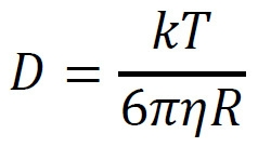
此差異允許基於AOI (相關區域)之子區域之中值強度值來定量濃度值,如上文關於圖12A-C及15所描述以及下文關於特定資料操作所論述。This difference allows concentration values to be quantified based on sub-region median intensity values of the AOI (region of interest), as described above with respect to Figures 12A-C and 15 and discussed below with respect to specific data manipulations.
圖20描繪根據特定實施例產生之滴定曲線。特定言之,圖20描繪對應於IgG之已知量(在x軸上以微克/毫升展示)之一系列絕對值(在y軸上標記為「晶片上分析效價得分」)。特定言之,用於產生圖20中展示之滴定曲線之IgG之已知量為0.001526、0.003052、0.006104、0.012207、0.024414、0.048828、0.097656、0.195313、0.390625、0.78125、1.5625、3.125、6.25、12.5微克/毫升。Figure 20 depicts titration curves generated according to certain embodiments. In particular, Figure 20 depicts a series of absolute values (labeled "on-wafer assay titer score" on the y-axis) corresponding to a known amount of IgG (shown in micrograms/ml on the x-axis). In particular, the known amounts of IgG used to generate the titration curves shown in Figure 20 were 0.001526, 0.003052, 0.006104, 0.012207, 0.024414, 0.048828, 0.097656, 0.195313, 0.390625, 0.78125, 1.5625, 3.125, 6.5 μg/g/6.5 ml.
為了產生表示圖20中展示之IgG之已知量之絕對值(經標記之分析得分),在含有經FITC標記之CPD 4之溶液中培育已知量之IgG。為了確保IgG之所有複本之結合及偵測,溶液中包括6倍量的結合IgG之所有複本所需之經FITC標記之CPD 4。接著,由溶液灌注微流體裝置45分鐘,接著用細胞株培養基(ThermoFisher CD CHO培養基)以10微升/秒之速度沖洗通道。在沖洗通道之後,使經FITC標記之CPD 4及IgG自腔室擴散至通道保持10分鐘。接著,將微流體裝置成像且用於產生如下文所描述之微流體裝置中的各腔室之分析得分。此過程最初在最高量(亦即,12.5微克/毫升)之IgG下進行,且每次使用較低量之IgG連續重複。To generate absolute values representing known amounts of IgG shown in Figure 20 (labeled analysis scores), known amounts of IgG were incubated in solutions containing FITC-labeled
在將微流體裝置成像之後,藉由獲得微流體裝置中之各腔室之所產生之個別絕對值之平均值來計算各已知量之IgG之分析得分。藉由獲得如上文關於圖12-15所描述之腔室之所產生之濃度值之斜率來產生個別絕對值中之每一者。特定言之,基於濃度值來計算各腔室之斜率,該等濃度值係基於所選擇的AOI產生。在產生濃度值之前,將影像標準化且經歷增益校正因子,如上文關於圖13A-B所描述。在計算各腔室之斜率之後,使用微流體裝置中之所有腔室之所有斜率之平均值作為分析得分。After imaging the microfluidic device, the analysis score for each known amount of IgG was calculated by taking the average of the individual absolute values generated for each chamber in the microfluidic device. Each of the individual absolute values is generated by obtaining the slope of the resulting concentration values for the chamber as described above with respect to Figures 12-15. In particular, the slope of each chamber is calculated based on the concentration values generated based on the selected AOI. Before generating density values, images were normalized and subjected to gain correction factors, as described above with respect to Figures 13A-B. After calculating the slope for each chamber, the average of all slopes for all chambers in the microfluidic device was used as the analysis score.
在產生之後,可使用滴定曲線(諸如圖20中所描繪之滴定曲線)產生未知量的分泌型分析物之絕對值。如圖20中所示,可藉由任何線擬合演算法來擬合滴定曲線中之分析得分,以產生定義絕對值(亦即,分析得分)與已知量之分析物(亦即,IgG)之間的關係之斜率等式。接著,可使用斜率等式產生表示在實驗條件(亦即,產生未知量之分析物之細胞)下存在之分析物之量之絕對值,得到在實驗條件下觀測到的分析得分。為了產生圖20中展示之滴定曲線,使用Tableau軟體產生基於分析得分之標準差的使用95%置信區間之對數擬合模型。After generation, a titration curve, such as the one depicted in Figure 20, can be used to generate absolute values for unknown amounts of secreted analytes. As shown in Figure 20, the analytical scores in the titration curve can be fitted by any line fitting algorithm to generate a defined absolute value (ie, the analytical score) with a known amount of analyte (ie, IgG ) is the slope equation of the relationship. Next, the slope equation can be used to generate an absolute value representing the amount of analyte present under the experimental conditions (ie, cells producing an unknown amount of analyte), resulting in an analysis score observed under the experimental conditions. To generate the titration curves shown in Figure 20, Tableau software was used to generate a log-fit model using 95% confidence intervals based on the standard deviation of the analysis scores.
如圖20中所示,已知量之IgG之分析得分說明以約1微克/毫升起始之線性關係。亦即,分析得分說明回應於增加量之IgG的成比例增加。在低於1微克/毫升之濃度下,未觀測到線性關係。因此,圖20中展示之滴定曲線展示具有在約1微克/毫升下準確定量之下限之動態範圍。圖20中展示之滴定曲線未說明上限,因為對應於最高量之IgG之分析得分在分析得分之範圍內,該分析得分呈現在已知量之IgG下之線性關係。As shown in Figure 20, the analytical scores for known amounts of IgG illustrate a linear relationship starting at about 1 microgram/ml. That is, the analysis score illustrates a proportional increase in response to increasing amounts of IgG. At concentrations below 1 μg/ml, no linear relationship was observed. Thus, the titration curve shown in Figure 20 exhibits a dynamic range with an accurate lower limit of quantitation at about 1 μg/ml. The titration curve shown in Figure 20 does not illustrate an upper limit, as the assay score corresponding to the highest amount of IgG is within the range of assay scores that exhibit a linear relationship for known amounts of IgG.
如圖20中所描繪之曲線中所示,通常在實驗條件(亦即,腔室內之分泌IgG之細胞)下觀測到的分析得分在滴定曲線中以灰色標記且標記為「分析效價之典型範圍」。因為在實驗條件下觀測到的分析得分在說明與已知量之IgG之線性關係的分析得分之範圍內,因此關於圖20產生之斜率可以用於計算在實驗條件下通常產生之IgG之量。As shown in the curves depicted in Figure 20, the assay scores typically observed under experimental conditions (ie, IgG-secreting cells within the chamber) are marked in grey in the titration curves and labeled "Typical for assay titers" Scope". Because the assay scores observed under experimental conditions were within the range of assay scores that illustrate a linear relationship to known amounts of IgG, the slopes generated with respect to Figure 20 can be used to calculate the amount of IgG typically generated under experimental conditions.
套組 . 可提供用於評估生物學微物件或由其產生之生物學微物件群體之分析物之分泌量之套組,其包括:微流體裝置,其包含具有流動區域之殼體;及腔室,其中腔室以流體方式連接至流動區域,且其中流動區域及腔室經組態以含有流體介質;及報導分子,其包含可偵測標記及經組態以結合分析物之結合組分。 Kit . A kit may be provided for assessing the secretion amount of an analyte of a biological micro-object or a population of biological micro-objects generated therefrom, comprising: a microfluidic device comprising a housing having a flow region; and a cavity a chamber, wherein the chamber is fluidly connected to a flow region, and wherein the flow region and the chamber are configured to contain a fluid medium; and a reporter molecule that includes a detectable label and a binding component configured to bind the analyte .
在套組之各種實施例中,微流體裝置之腔室可具有隔離區域及以流體方式將隔離區域連接至流動區域之連接區域,其中隔離區域及連接區域經組態使得流體介質實質上僅藉由擴散而在腔室之流動區域與隔離區域之間交換。在各種實施例中,微流體裝置之殼體可包括基底,其上安置有流動區域及腔室。在一些實施例中,殼體之基底可包括具有介電泳組態之基板。介電泳組態可為光學致動的。在各種實施例中,流動區域可為通道。在一些實施例中,微流體裝置可包括複數個腔室,其可與如本文中所描述之任何腔室類似地經組態。在一些實施例中,微流體裝置之至少一個內表面包括經共價修飾之表面。在各種實施例中,套組之微流體裝置可與本文中所描述之任何微流體裝置類似地經組態且可以任何組合形式具有微流體迴路元件之任何組分、尺寸及/或多樣性。In various embodiments of the kit, the chamber of the microfluidic device can have an isolation region and a connection region fluidly connecting the isolation region to the flow region, wherein the isolation region and the connection region are configured such that the fluid medium is substantially only Exchange between the flow area and the isolation area of the chamber by diffusion. In various embodiments, the housing of the microfluidic device can include a substrate on which the flow regions and chambers are disposed. In some embodiments, the base of the housing may include a substrate having a dielectrophoretic configuration. The dielectrophoretic configuration can be optically actuated. In various embodiments, the flow regions may be channels. In some embodiments, a microfluidic device can include a plurality of chambers, which can be configured similarly to any of the chambers as described herein. In some embodiments, at least one inner surface of the microfluidic device includes a covalently modified surface. In various embodiments, the microfluidic devices of the kit can be configured similarly to any of the microfluidic devices described herein and can have any composition, size, and/or diversity of microfluidic circuit elements in any combination.
在套組之各種實施例中,報導分子之結合組分可包括至少一種胺基酸及/或至少一種核酸。在一些實施例中,報導分子之結合組分可包括肽或蛋白質。在各種實施例中,肽或蛋白質結合組分可為結合人類或鼠類IgG之肽或蛋白質。在一些實施例中,報導分子之結合組分可為以下中之任一者:CPD 1、CPD 2、CPD 3、CPD 4、CPD 7、CPD 8、CPD 9、CPD 10、CPD 11、CPD 12、CPD 13或CPD 14 (參見表1)。在一些實施例中,報導分子之結合組分可CPD 1、CPD 2、CPD 3或CPD 4 (參見表1)。在一些實施例中,結合人類或鼠類IgG之蛋白質結合組分可為CPD 1或CPD 2 (參見表1)。在其他實施例中,報導分子之結合組分包括適體。在各種實施例中,適體可為CPD 5或CPD 6 (表1)。在一些實施例中,報導分子之適體結合組分結合於IgG之Fc。In various embodiments of the kit, the binding component of the reporter molecule can include at least one amino acid and/or at least one nucleic acid. In some embodiments, the binding component of the reporter molecule may comprise a peptide or protein. In various embodiments, the peptide or protein binding component may be a peptide or protein that binds human or murine IgG. In some embodiments, the binding component of the reporter molecule can be any of the following:
在套組之各種實施例中,報導分子之可偵測標記可包括可見、發光、磷光或螢光標記。在一些實施例中,可偵測標記為螢光標記。螢光標記可為若丹明、螢光素或花青螢光染料。In various embodiments of the kit, the detectable label of the reporter molecule may comprise a visible, luminescent, phosphorescent or fluorescent label. In some embodiments, the detectable label is a fluorescent label. The fluorescent label can be a rhodamine, fluorescein or cyanine fluorescent dye.
在套組之各種實施例中,套組亦可包括流體介質。流體介質可經組態以維持、擴增或向生物學微物件或由其產生之生物學微物件之群體提供選擇性壓力。In various embodiments of the kit, the kit may also include a fluid medium. The fluid medium can be configured to maintain, amplify, or provide selective pressure to biological micro-objects or populations of biological micro-objects generated therefrom.
在套組之各種實施例中,套組亦可包括經組態以調節微流體裝置之一或多個表面之試劑。在一些實施例中,試劑可經組態以共價修飾微流體裝置之一或多個表面。In various embodiments of the kit, the kit may also include reagents configured to condition one or more surfaces of the microfluidic device. In some embodiments, the reagents can be configured to covalently modify one or more surfaces of the microfluidic device.
根據各種實施例,提供用於評估生物學微物件或由其產生之生物學微物件群體之分析物之分泌量之套組。套組可包括微流體裝置及報導子複合物。微流體裝置可包含具有流動區域及複數個腔室之殼體,其中各腔室以流體方式連接至流動區域,且其中流動區域及腔室經組態以含有流體介質。報導子複合物可包含經組態以結合於分泌型分析物之第一複合物組分,及結合於第一複合物組分且包含可偵測標記之第二複合物組分,其中分泌型分析物與第一複合物組分之結合可抑制或防止第二複合物組分與第一複合物組分之結合。電腦實施之系統 According to various embodiments, kits are provided for assessing the secretion amount of an analyte of a biological micro-object or a population of biological micro-objects generated therefrom. A kit can include a microfluidic device and a reporter complex. A microfluidic device can include a housing having a flow region and a plurality of chambers, wherein each chamber is fluidly connected to the flow region, and wherein the flow region and the chamber are configured to contain a fluid medium. The reporter complex can comprise a first complex component configured to bind to a secreted analyte, and a second complex component bound to the first complex component and comprising a detectable label, wherein the secreted The binding of the analyte to the first complex component can inhibit or prevent the binding of the second complex component to the first complex component. computer-implemented system
電腦實施之系統
. 圖25為說明可實施各種實施例之電腦系統3100之方塊圖。根據各種實施例,電腦系統3100可包括匯流排3102或用於傳達資訊之其他通訊機構,及用於處理資訊之與匯流排3102耦合之處理器3104。在各種實施例中,電腦系統3100亦可包括記憶體3106,其可為如所說明之隨機存取記憶體(RAM)或其他動態儲存裝置,其與匯流排3102耦合以用於確定由處理器3104執行之指令。記憶體3106亦可用於在待由處理器3104執行之指令之執行期間儲存暫時性變數或其他中間資訊。在各種實施例中,電腦系統3100可進一步包括另一記憶3108,諸如唯讀記憶體(ROM)3108或其他靜態儲存裝置,其與匯流排3102耦合以用於儲存靜態資訊及處理器3104之指令。可提供儲存裝置3110 (諸如磁碟或光碟)且與匯流排3102耦合以用於儲存資訊及指令。 Computer Implemented System . Figure 25 is a block diagram illustrating a
在各種實施例中,電腦系統3100可經由匯流排3102耦接至顯示器3112,諸如陰極射線管(CRT)或液晶顯示器(LCD),以用於向電腦使用者顯示資訊。輸入裝置3114 (包括字母數字及其他按鍵)可耦接至匯流排3102以用於向處理器3104傳達資訊及命令選擇。另一類型之使用者輸入裝置為用於將方向資訊及命令選擇傳達至處理器3104且用於控制顯示器3112上之游標移動的游標控制件3116,諸如,滑鼠、軌跡球或游標方向按鍵。此輸入裝置3114通常在兩個軸,第一軸(亦即,x)及第二軸(亦即,y)上具有兩個自由度,其允許裝置指定平面中之位置。然而,應理解,本文中亦涵蓋實現3維(x、y及z)游標移動之輸入裝置3114。In various embodiments, the
與本文中之各種實施例一致,可由電腦系統3100回應於執行記憶體3106中所含的一或多個指令之一或多個序列之處理器3104而提供結果。可將此類指令自另一電腦可讀媒體或電腦可讀儲存媒體(諸如儲存裝置3110)讀取至記憶體3106中。執行記憶體3106中所含的指令序列可引起處理器3104進行本文中所描述之方法。或者,可使用硬佈線電路代替軟體指令或與軟體指令組合使用以實施本發明之教示。因此,本發明之教示之實施不限於硬體電路及軟體之任何特定組合。Consistent with the various embodiments herein, results may be provided by
如本文中所使用,術語「電腦可讀媒體」(例如,資料儲存器、資料儲存裝置等)或「電腦可讀儲存媒體」係指任何參與向處理器3104提供用於執行之指令之媒體。此類媒體可呈多種形式,包括(但不限於)非揮發性媒體、揮發性媒體及傳輸媒體。非揮發性媒體之實例可包括(但不限於)光學、固態、磁碟,諸如儲存裝置3110。揮發性媒體之實例可包括(但不限於)動態記憶體,諸如記憶體3106。傳輸媒體之實例可包括(但不限於)同軸電纜、銅線及光纖,包括包含匯流排3102之導線。As used herein, the term "computer-readable medium" (eg, data storage, data storage device, etc.) or "computer-readable storage medium" refers to any medium that participates in providing instructions to
電腦可讀媒體之常見形式包括例如軟碟、可撓性碟、硬碟、磁帶或任何其他磁性媒體、CD-ROM、任何其他光學媒體、打孔卡、紙帶、具有孔圖案之任何其他實體媒體、RAM、PROM及EPROM、FLASH-EPROM、任何其他記憶體晶片或卡匣,或可供電腦讀取之任何其他有形媒體。Common forms of computer readable media include, for example, floppy disks, flexible disks, hard disks, magnetic tapes or any other magnetic media, CD-ROMs, any other optical media, punch cards, paper tape, any other entity with a pattern of holes Media, RAM, PROM and EPROM, FLASH-EPROM, any other memory chip or cartridge, or any other tangible medium that can be read by a computer.
除電腦可讀媒體以外,可以通訊設備或系統中包括之傳輸媒體上之信號形式提供指令或資料,以向電腦系統3100之處理器3104提供用於執行之一或多個指令之序列。舉例而言,通訊設備可包括具有指示指令及資料之信號的收發器。指令及資料經組態以使一或多個處理器實施本文中之揭示內容中所概述之功能。資料通訊傳播連接件之代表性實例可包括(但不限於)電話數據機連接件、廣域網路(WAN)、區域網路(LAN)、紅外線資料連接件、NFC連接件等。In addition to computer-readable media, instructions or data may be provided in the form of signals on transmission media included in a communication device or system to provide a sequence for execution of one or more instructions to
應瞭解,本文中所描述之方法、流程圖、圖及隨附揭示內容可使用呈獨立裝置形式之電腦系統3100或在共用電腦處理資源之分散式網路(諸如雲計算)上實施。分析物定量器系統 It should be appreciated that the methods, flowcharts, diagrams, and accompanying disclosure described herein may be implemented using
分析物定量器系統 . 根據各種實施例,揭示用於測定由微物件產生之分析物之量之系統及方法。分析物可包括例如來自微物件之分泌物,其中微物件可為生物學微物件。分析物可包括例如蛋白質;醣;核酸;抗體;抗原;除蛋白質、醣或核酸以外之有機分子;囊泡;或病毒。分析物之量可為如下文將論述之相對量。 Analyte Quantifier System . According to various embodiments, systems and methods for determining the amount of analyte produced by a micro-object are disclosed. Analytes can include, for example, secretions from micro-objects, where the micro-objects can be biological micro-objects. Analytes can include, for example, proteins; sugars; nucleic acids; antibodies; antigens; organic molecules other than proteins, sugars, or nucleic acids; vesicles; or viruses. The amount of analyte can be a relative amount as will be discussed below.
圖26為根據各種實施例之用於測定由微物件產生之分析物之量的系統之示意圖。如本文中所描繪,系統3200可包括影像獲取單元3202、影像處理單元3204及用於經由相關輸入裝置(未描繪)來輸出資料及接收使用者輸入之顯示器3212。26 is a schematic diagram of a system for determining the amount of analyte produced by a micro-object, according to various embodiments. As depicted herein,
影像獲取單元3202(諸如(但不限於)以上圖1中所描繪之成像模組164)可包括微流體裝置固持器3214 (諸如(但不限於)以上圖1及3B中所描繪之支撐結構104及300)及成像元件3216 (諸如(但不限於)以上提及之成像裝置194)。Image acquisition unit 3202 (such as, but not limited to,
微流體裝置固持器3214可經定向及設計以固定微流體裝置。微流體裝置可包括本文中所描述之各種實例中之任一者(諸如(但不限於)以上圖1B-1C、2A-2B、2D、2G-2H、3A、4A-4C、5A-5C、9B、10B、11A-11B及12A-12B中所描繪之微流體裝置200、230、250、280、290、320、400、500、900、1000、1100及1200)。或者,固持器3214可與微流體裝置整合在一起。微流體裝置可包括流動區域及一個腔室或複數個腔室,其可以流體方式連接至流動區域,其中各腔室可固持一或多個微物件。如先前所述,腔室可為例如腔室。應瞭解,腔室視其用於之特定應用所需要而可具有任何形狀、大小或定向。如先前所論述,流動區域可為單一微流體通道或複數個微流體流動通道(諸如(但不限於)以上圖1A及2A-2C中所描繪之通道122,及如以上圖2D-2F中所描繪之流動通道264),其提供單一流道或複數個流道(諸如(但不限於)以上圖1A及2B中所描繪之流道106,及如以上圖2C-2D、4A-4C、5A、9B、10B、12A中所描繪之介質之流242及278)。流動區域可與單一或複數個腔室流體連通。或者,流動區域可經由可逆密封件(諸如閥)與單一腔室或複數個腔室流體連通。流動區域可經組態以經由如先前所描述之入口接收材料流。材料流可包括例如微物件、結合劑或試劑之流,或包括材料之介質之流。微流體裝置可進一步經組態以接收通過流道且進入腔室之結合劑(諸如報導分子)之流。在結合於分析物時,結合劑可發射電磁輻射,諸如由結合劑之可偵測標記發射之光(例如,螢光、UV等)。分析物可包括例如來自微物件之分泌物,其中微物件可為生物學微物件。分析物可包括例如蛋白質;醣;核酸;抗體;抗原;除蛋白質、醣或核酸以外之有機分子;囊泡;或病毒。The
成像元件216可經組態以擷取微流體裝置之複數個腔室及流動區域之一或多個分析影像3222 (參見圖27)。成像元件3216可進一步經組態以擷取待結合一或多個分析影像3222分析及實施之一或多個相應背景影像3218 (參見圖27)及/或一或多個相應信號參考影像3220 (參見圖3),如下文詳細論述。The
在將任何外來物質(諸如微物件、結合劑或其他試劑)引入微流體裝置之前,可藉由成像元件3216來獲取背景影像3218 (參見例如圖27)。由此,背景影像3218擷取裝置中,特定言之相關區域中之任何背景雜訊,如下文進一步論述。背景雜訊可歸因於例如假像或儀器設置及成像參數,例如來自激發源之光、照相機雜訊及環境光。背景雜訊亦可歸因於由例如樣品、容器、成像介質之自體螢光施加之背景螢光,或由未結合於特定目標之螢光團產生之螢光。背景影像中包括哪些影像區域取決於系統上如何實施影像。舉例而言,如下文將詳細地描述,取決於所使用之校準方法,可能需要不同的背景影像區域。A
在將結合劑引入腔室達到使結合劑濃度在相關區域(「AOI」)中平衡之程度之後,可藉由成像元件3216來獲取信號參考影像3220 (參見例如圖27)。由此,信號參考影像3220擷取裝置中之影像獲取畸變。此類畸變可由例如微流體或成像元件設計引起。影像畸變類型可包括例如影像邊緣效應、透視畸變、針筒畸變、枕形畸變、鬍子畸變及色像差。信號參考影像區域可包括AOI、靠近腔室及相關AOI之流動區域或其兩者之影像。信號參考影像中包括哪些影像區域取決於系統上如何實施影像。舉例而言,如下文進一步詳細提供,取決於由系統實施之校準方法,可利用不同的信號參考影像區域。After the binding agent is introduced into the chamber to the extent that the concentration of binding agent equilibrates in the area of interest ("AOI"), a
圖26之系統3200之影像處理單元3204可以通訊方式連接至影像獲取單元3202。在各種實施例中,影像處理單元3204可包括相關區域測定引擎3206 (AOI引擎3206)及評分引擎3210。應瞭解,描繪為影像處理單元3204之一部分(及本文中所描述之)各組件(例如,引擎、模組等)可實施為硬體、韌體、軟體或其任何組合。The
在各種實施例中,影像處理單元3204可實施為具有影像獲取單元3202之整合式儀器系統總成。亦即,影像處理單元3204及影像獲取單元3202可收納於同一個殼體總成中且經由習知裝置/組件連接構件(例如,串列匯流排、光學電纜線、電學電纜線等)通訊。In various embodiments, the
在各種實施例中,影像處理單元3204可實施為獨立計算裝置(如以上圖26中所展示),其經由光學、串聯埠、網路或數據機連接以通訊方式連接至影像獲取單元3202。舉例而言,影像處理單元可經由LAN或WAN連接來連接,該連接實現將由影像獲取單元3202獲取之成像資料傳輸至分析之影像處理單元3204。In various embodiments, the
在各種實施例中,可在共有電腦處理資源之分散式網路(諸如,雲計算網路)上實施影像處理單元3204之功能,該分散式網路經由WAN(或等效)連接以通訊方式連接至影像獲取單元3202。舉例而言,可分割影像處理單元3204之功能性以在雲處理服務(諸如AMAZON WEB SERVICES™)上之一或多個計算節點中實施。In various embodiments, the functions of
相關區域測定引擎3206 (AOI引擎3206)可經設計及組態以接收來自成像元件3216之所擷取之分析影像且定義分析影像中所描繪之各腔室之AOI。相關區域測定引擎3206可經程式化以定義適當的AOI,此係藉由在AOI內包括對量測分析物濃度波動之敏感性最高的腔室內之影像區域來實現。舉例而言,此可為腔室內可由成像元件3216量測到電磁輻射(諸如光發射(例如,螢光、UV等))之最小波動之區域。此外,影像區域可包括對量測分析物波動時腔室中之微物件之位置之敏感性最低之影像區域。舉例而言,此將為腔室內電磁輻射(諸如光發射(例如,螢光、UV等))之量測結果之敏感性受腔室中微物件之存在之影響最小的區域。AOI甚至亦可定義為沿相應腔室與流動區域之間的擴散軸3302延伸(參見圖28),該流動區域與該相應腔室流體連通。如下文將更詳細地論述,此AOI亦可為腔室之未波及區域,如例如圖32中所說明。The relevant area determination engine 3206 (AOI engine 3206) can be designed and configured to receive the captured analysis image from the
在圖28中所描繪之例示性實施例中,可使用關於微流體裝置及其相應腔室之空間資訊來測定擴散軸3302。該空間資訊可來源於系統3200中所含的CAD模型、相關軟體或用於產生既定的未經排列之AOI 3224之單獨的套裝軟體。接著,用於成像元件及微流體裝置之校準演算法可將影像資料映射至此CAD模型以獲得適當的擴散軸3302。基於此映射應用空間校正轉變3226,相關區域測定引擎3206可產生經排列之AOI 3228之集合。AOI可由相關區域測定引擎3206自動測定或可經由顯示器3212之使用者輸入來人工測定。In the exemplary embodiment depicted in Figure 28, the
圖26之系統3200之評分引擎3210可經設計及組態以分析各腔室之相關區域內之至少一部分影像區域,以測定指示各腔室中之分析物之量之得分。此外,因為得分可為可藉由評分引擎3210與其他得分進行比較以指示分析物之相對量或濃度之無量綱值,對於使用者,可將所測定之得分轉換為濃度單位。The
為了測定得分,評分引擎3210可使用各種模型。如下文所論述,一些模型可為利用例如定量結合於各腔室、流動區域或其兩者中之分析物的結合劑(諸如報導分子)之量之螢光資料之模型。分析物可包括例如來自腔室內之微物件之分泌物,其中微物件可為生物學微物件。評分引擎3210可使用結合之報導分子資料(諸如螢光值),特定言之,在整個AOI上,以測定相應腔室之得分,其指示該腔室中之分析物之量。評分模型之非限制性實例包括對各腔室之AOI之一部分影像區域上的光發射資料(例如,螢光值或一些其他類型之可偵測信號)應用線性回歸分析、對AOI應用S形曲線模型、使用AOI之平均強度(其對於產生相關分析物之生物學微物件之位置而言為恆定的)或整合各腔室之AOI之一部分影像區域上的光發射資料(例如,螢光值或一些其他類型之可偵測信號)。To determine the score, the
舉例而言,S形曲線模型化藉由S形曲或邏輯、曲線、等式及細節來模擬AOI中之擴散梯度。使用參數(諸如生長率、漸近線之間的差及反曲點位置)之組合之定量模型可產生必需的準確性及/或精確性。取決於所使用之S形曲線之確切形式,可例如藉由非線性回歸或曲線回歸來估計模型之參數。通用模型參數估計技術包括例如雷文柏格-馬括特(Levenberg-Marquardt)、單工及模擬黏接。探試技術可用於初始化參數以進一步幫助確保迭代擬合技術(諸如非線性回歸)期間之收斂。舉例而言,可藉由AOI之端值處的子區域之平均值來粗略地估計上漸近線及下漸近線。For example, sigmoid modeling simulates diffusion gradients in AOI by sigmoid or logic, curves, equations, and details. A quantitative model using a combination of parameters such as growth rate, difference between asymptotes, and inflection point location can yield the requisite accuracy and/or precision. Depending on the exact form of the sigmoid curve used, the parameters of the model can be estimated, for example, by nonlinear regression or curve regression. Common model parameter estimation techniques include, for example, Levenberg-Marquardt, simplex, and simulated bonding. Heuristic techniques can be used to initialize parameters to further help ensure convergence during iterative fitting techniques such as nonlinear regression. For example, the upper and lower asymptotes can be roughly estimated by the average of the subregions at the endpoints of the AOI.
或者,如圖27之實施例中所描繪,在對AOI應用以上評分模型之前,評分引擎3210可沿擴散軸3302將經排列之AOI 3228劃分為單獨的區段3230 (參見圖28)。圖28描繪微流體裝置之一部分之實例,該微流體裝置包括流動區域3308、腔室3306、擴散軸3302、複數個區段3304及微物件3310。區段3304之數目可視進行必要的評分模型之需要而變化。區段3304之數目可為例如20。對於區段3304,評分引擎3210可計算中位值3232,其中值可為例如電磁輻射值,諸如螢光值,其指示結合於各腔室3306、流動區域3308或其兩者內之分析物之結合劑(諸如報導分子)之量。分析物可包括例如來自微物件3310之分泌物,其中微物件可為生物學微物件。接著,評分引擎3210可經由子部分定量過程3234,基於參數集合來測定區段之子集(或組) 3304。Alternatively, as depicted in the embodiment of Figure 27, prior to applying the above scoring model to the AOI, the
評分引擎3210可使用編碼至評分引擎3210中或在其遠端提供之指令集合(例如,無線、遠端軟體程式、使用者輸入),經由子部分定量過程3234來測定區段之子集(或組)3304。指令集合可基於例如使用例如微物件類型、腔室中之微物件計數、區段計數(或組計數)、子部分計數及子部分位置之不同組合進行之先前數值模擬。使用此資料,可編碼使相關微物件與各種數值模擬相關聯之指令,以測定區段之適當子集以用於相關生物學微物件之分析。Scoring
區段3304之子集可包括總區段計數內之測定該腔室3306之得分所必需的區段之任何組。舉例而言,基於所提供之參數或指令之集合,評分引擎3210可將組9-13鑑別為用於測定特定腔室之得分之組之子集。應用評分模型,諸如先前描述之模型,評分引擎3210接著可測定該腔室之得分,諸如分泌得分3236。The subset of
或者,根據各種實施例,影像處理單元3204可進一步包括校準引擎3208,如例如圖26及圖27中所描繪。校準引擎3208可經設計及組態以對由來自微流體裝置及在分析影像擷取期間之背景雜訊引起之影像畸變應用各腔室之AOI標準化過程3238。接著,可藉由評分引擎3210對所得經校準之影像AOI進行評分。如上所述,背景雜訊可歸因於例如假像或儀器設置及成像參數,例如來自激發源之光、照相機雜訊及環境光。背景雜訊亦可歸因於由例如樣品、容器、成像介質之自體螢光施加之背景螢光,或由未結合於特定目標之螢光團產生之螢光。分析影像擷取期間之影像畸變可由例如微流體裝置設計或成像裝置設計引起。影像畸變類型可包括例如影像邊緣效應、投影儀不均勻性、照相機虛化、透視畸變、針筒畸變、枕形畸變、鬍子畸變及色像差。Alternatively, according to various embodiments, the
對於先前來自微流體裝置及/或在分析影像擷取期間引入之影像畸變,校準引擎3208可經設計及組態以標準化各腔室之AOI,或至少各腔室之AOI之影像區域。校準引擎3208可藉由自分析影像及/或信號參考影像減去背景影像且考慮信號參考影像中擷取之影像獲取畸變來達成此目的。接著,可藉由評分引擎3210對所得經標準化之影像AOI進行評分。The
存在用於標準化影像以用於特徵提取及異常偵測之各種模型。在一個實施例中,經由統計推斷進行之資料排除可在標準化AOI之前移除異常。可藉由基本統計轉換(諸如計算所有AOI資料之分佈內的既定資料點之z得分)來偵測異常,諸如可具有極低或極高強度之外來材料。Various models exist for normalizing images for feature extraction and anomaly detection. In one embodiment, data exclusion via statistical inference can remove anomalies prior to normalizing the AOI. Anomalies, such as foreign materials that may have very low or very high intensities, can be detected by basic statistical transformations, such as computing z-scores for a given data point within the distribution of all AOI data.
根據各種實施例,經由統計推斷進行之資料排除可在標準化AOI之前移除異常。因為理想的擴散概況通常沿與擴散軸正交之任何線具有恆定值,有可能以統計方式推斷AOI中是否存在異常(諸如外來材料)及自模型化排除此等資料點。AOI中各資料點可轉換成z得分,指示其由隨機變動引起之出現概率。舉例而言,考慮AOI,其中I
為既定點處之強度值,µ為平均強度值,σ為標準差,y
表示擴散方向且x
與其正交,可經由等式(1)來計算既定點處之z得分:
由以上等式產生之z得分可用於排除具有大於既定閾值之z得分幅值之資料。可重複此過程以迭代地移除不同大小及強度之異常。The z-score generated by the above equation can be used to exclude data with z-score magnitudes greater than a predetermined threshold. This process can be repeated to iteratively remove anomalies of different sizes and intensities.
根據各種實施例,分段模型化可在標準化AOI之前移除異常。基於擴散概況理想地在沿與擴散軸正交之任何方向上恆定之原理,可獨立地跨越AOI之N個行來擬合分析模式。在理想系統中,此等模型將皆產生相同參數估計值。在實踐中,其將為正態分佈。然而,在異常(諸如未對準或存在外來材料)之情況下,參數估計值之分佈中將存在其他模式。藉由組合資訊,諸如針對AOI-欄資料之模型與所有參數估計值之分佈內的既定參數之量值之發生率之相關性,可測定哪些模型反映異常結果且因此應自進一步分析排除。此可與上文所描述之z得分技術結合使用,以適當地標準化相關資料。According to various embodiments, segmented modeling may remove anomalies prior to normalizing the AOI. Based on the principle that the diffusion profile is ideally constant along any direction orthogonal to the diffusion axis, the analytical model can be fitted independently across the N rows of the AOI. In an ideal system, these models would all produce the same parameter estimates. In practice it will be normally distributed. However, in the case of anomalies such as misalignment or the presence of foreign material, there will be other patterns in the distribution of parameter estimates. By combining information, such as the correlation of the model for the AOI-column data with the incidence of the magnitude of a given parameter within the distribution of all parameter estimates, it is possible to determine which models reflect abnormal results and should therefore be excluded from further analysis. This can be used in conjunction with the z-score technique described above to properly normalize the relevant data.
根據各種實施例,根據等式(2),可使用背景影像「a」及信號參考影像「c」以擷取方式產生點x,y處之分析影像之標準化值(I 校正
):
根據各種實施例,產生G得分以標準化AOI中之所有資料點。在擷取背景影像「a」及信號參考影像「c」之後,可根據等式(3)來計算校正因子「G」:
接著,對於AOI之評分,可如下應用校正因子G以根據等式(4)來測定分析影像之標準化值(I 校正
):
使用分析影像之標準化值,評分引擎3210可進一步經設計及組態以分析各腔室之標準化相關區域之一部分,以測定指示各腔室中之分析物之量之得分。如上文所論述,評分模型之實例包括對各腔室之標準化相關區域之一部分應用線性回歸分析,或整合各腔室之一部分標準化相關區域上之螢光值(或一些其他類型之可偵測信號)。Using the normalized values of the analyzed images, the
或者,根據各種實施例,而非使用AOI之信號參考影像及背景影像,校準引擎3208可應用上述實施例以使用靠近腔室及相關AOI之流動區域以及微流體裝置之不含有生物學微物件之其他區域之信號參考影像及/或背景影像進行校準。此等「非AOI」影像可與分析影像資料結合使用以標準化分析影像資料,如上文詳細論述。Alternatively, according to various embodiments, instead of using the signal reference image and background image of the AOI, the
根據各種實施例,可將影像獲取單元3202及影像處理單元3204整合至單一實體單元中。或者,影像獲取單元3202及影像處理單元3204可單獨定向,在獨立單元中提供使得各單元仍以通訊方式連接以交換資訊。According to various embodiments, the
上文所描述之影像處理單元3204之各組件可為硬體或可部分或完全為軟體模組。The components of the
圖29為展示用於測定由微物件產生之分析物之量的方法之示例性流程圖。如本文中所描繪,步驟3410詳細說明可由圖26之系統3200之影像獲取單元3202之相關區域引擎3206利用之例示性工作流程。在步驟3410中,相關區域引擎3206接收微流體裝置之成像資料,該微流體裝置包括流動區域及複數個以流體方式連接至流動區域之腔室,其中成像資料可包括背景雜訊影像、信號參考影像及分析物分析影像中之一者或組合。在將任何外來物質(諸如微物件、結合劑或其他試劑)引入微流體裝置之前,可藉由成像元件3216來獲取背景影像。由此,背景影像擷取任何與系統3200相關聯之背景雜訊及裝置上之區域之影像擷取。先前已描述背景雜訊之實例。在將結合劑引入腔室達到使得裝置中之結合劑濃度平衡之程度之後,可藉由成像元件3216來獲取信號參考影像。由此,信號參考影像擷取與系統3200相關聯之影像獲取畸變及裝置上之區域之相關影像擷取。29 is an exemplary flowchart showing a method for determining the amount of analyte produced by a micro-object. As depicted herein,
所接收之成像資料可包括例如由螢光測定之螢光發射資料,該螢光係由結合於一或多個腔室、流動區域或其兩者中之分析物之結合劑(諸如報導分子)發射。分析物可包括例如來自微物件之分泌物,其中微物件可為生物學微物件。來自生物學微物件之分泌物可包括例如蛋白質、醣、核酸、具有小於3 Kd之分子量之有機分子或病毒。如先前所述,腔室可為例如腔室。Received imaging data may include, for example, fluorescence emission data measured by fluorescence from binding agents (such as reporters) of analytes bound in one or more chambers, flow regions, or both emission. Analytes can include, for example, secretions from micro-objects, where the micro-objects can be biological micro-objects. Secretions from biological micro-objects can include, for example, proteins, sugars, nucleic acids, organic molecules with molecular weights less than 3 Kd, or viruses. As previously described, the chamber may be, for example, a chamber.
如本文中所描繪,步驟3420及3430詳細說明可由圖26之系統3200之影像處理單元3204之評分引擎3210利用之例示性工作流程。在步驟3420中,影像處理單元3204可定義各腔室之相關區域(「AOI」)。AOI可包括腔室內之對量測分析物濃度波動之敏感性最高之影像區域。流動區域AOI可進一步包括對量測分析物波動時對腔室中微物件之位置之敏感性最低之影像區域且此外,影像區域可沿腔室與流動區域之間的擴散軸延伸。As depicted herein,
在步驟3430中,評分引擎3210可藉由分析各腔室之一部分AOI來測定指示各腔室中之分析物之量之得分。為了測定各腔室之得分,評分引擎3210可使用如上文所論述之各種模型。一些模型可為利用例如螢光資料之模型,該螢光資料定量結合於分析物之結合劑(諸如報導分子)之量。分析物可包括例如來自腔室內之微物件之分泌物,其中微物件可為生物學微物件。評分引擎3210可使用結合之報導分子資料(或螢光值),特定言之,在整個AOI上,以測定相應腔室之得分,其指示該腔室中之分析物之量。評分模型之非限制性實例包括對各腔室之標準化相關區域之一部分應用線性回歸分析,或整合各腔室之一部分標準化相關區域上之螢光值(或一些其他類型之可偵測信號)。In
圖30說明可應用於成像資料以獲得分析物分析影像中之各腔室之標準化AOI之校準方法。如本文中所描繪,步驟3510至3530詳細說明可由圖26之影像處理單元3204之校準引擎3208利用之校準方法之例示性工作流程。Figure 30 illustrates a calibration method that can be applied to imaging data to obtain normalized AOI for each chamber in an analyte analysis image. As depicted herein, steps 3510-3530 detail an exemplary workflow of a calibration method that may be utilized by the
在步驟3510中,校準引擎3208可接收來自影像獲取單元3202之成像資料,如先前所論述,其可包括背景影像、信號參考影像及分析物分析影像之成像資料中之一者或組合。如先前所論述,成像資料可呈來自微流體裝置上之各腔室之相關區域之螢光值形式。經成像之螢光可為來源於背景雜訊(對於背景影像)、來自填充相關區域之結合劑(對於信號參考影像)或來自結合於分析物之結合劑(諸如報導分子,對於分析物分析影像)之發射之螢光,該分析物可包括例如來自腔室中存在之生物學微物件之分泌物。In
在步驟3520中,校準引擎3208可自信號參考影像及分析物分析影像值減除背景影像值。由此,自信號參考影像及分析物分析影像值移除系統中已存在之任何背景雜訊,以獲得兩種影像之不再受雜訊影響之背景校正值。In
在步驟3530中,校準引擎3208可藉由比較信號參考影像及分析物分析影像值之背景校正值來進一步校正分析物分析影像值,以考慮先前所描述之影像獲取畸變,其將在整個信號參考影像中鑑別。該比較將產生標準化分析物分析影像值,尤其在AOI內。上文提供用於測定標準化值之相關公式及計算方法之實例。In
使用標準化資料,評分引擎3210可藉由分析各腔室之當前經標準化之AOI之一部分來測定指示各腔室中之分析物之量之得分。Using the normalized data, the
取決於應用,可由各種手段實施本文中所描述之方法。舉例而言,此等方法可以硬體、韌體、軟體或其任何組合來實施。對於硬體實施,處理單元可在一或多個特殊應用積體電路(ASIC)、數位信號處理器(DSP)、數位信號處理裝置(DSPD)、可程式化邏輯裝置(PLD)、場可程式化閘陣列(FPGA)、處理器、控制器、微控制器、微處理器、電子裝置、經設計以執行本文中所描述之功能的其他電子單元或其組合內實施。The methods described herein can be implemented by various means, depending on the application. For example, these methods may be implemented in hardware, firmware, software, or any combination thereof. For a hardware implementation, the processing unit may be one or more of an application specific integrated circuit (ASIC), digital signal processor (DSP), digital signal processing device (DSPD), programmable logic device (PLD), field programmable FPGAs, processors, controllers, microcontrollers, microprocessors, electronic devices, other electronic units designed to perform the functions described herein, or combinations thereof.
在各種實施例中,本發明之教示之方法可實施為以習知程式化語言(諸如C、C++等)書寫之韌體及/或軟體程式及應用程式。若實施為韌體及/或軟體,則本文中所描述之實施例可在儲存用於引起電腦進行上文所描述之方法之程式的非暫時性電腦可讀媒體上實施。應理解,本文中所描述之各種引擎可在電腦系統(諸如圖25之電腦系統3100)上提供,藉此處理器3104將執行由此等引擎提供之分析及測定,運作由記憶體組件3106/3108/3110及經由輸入裝置3114提供之使用者輸入中之任一者或組合提供之指令。鉤狀區域模擬 In various embodiments, the methods of the teachings of the present invention may be implemented as firmware and/or software programs and applications written in conventional programming languages (such as C, C++, etc.). If implemented as firmware and/or software, the embodiments described herein may be implemented on a non-transitory computer-readable medium storing programs for causing a computer to perform the methods described above. It should be understood that the various engines described herein may be provided on a computer system, such as
將由腔室及流動區域構成之幾何結構內之層流及擴散運輸模型化,以測定腔室內對RMSA複合物(例如,結合之RMSA複合物、結合之複合物等)信號敏感之位置。使用單一腔室幾何結構以參數化模型。模擬中使用之邊界條件展示於圖40A中。當不具有可溶性報導分子(例如,報導分子、報導子等)之液體介質經由流動區域流如微流體時,在具有可溶性報導分子之液體介質預先流入流動區域之後,流體流場在時間上為恆定的且輸入流速率為4.8 mm/s以符合在分析之沖洗步驟期間以實驗方式使用之1.7 µL /s之體積流率。獨立地考慮各物質(例如,可溶性報導分子、RMSA複合物等)且在幾何結構中將游離可溶性報導分子之初始濃度設定為1 mol/m3 。濃度為擴散等式中之常數項,因此此值可針對標準曲線之各條件之實際值來標準化。在t=0時,將入口處之濃度設定為零以符合在進行分析之前之沖洗。通道之出口為自由邊界,允許將流體及分子運輸出幾何結構。Laminar and diffusive transport within the geometry consisting of the chamber and flow region is modeled to determine the locations within the chamber that are sensitive to RMSA complexes (eg, bound RMSA complexes, bound complexes, etc.). Use a single chamber geometry to parameterize the model. The boundary conditions used in the simulation are shown in Figure 40A. When a liquid medium without soluble reporter molecules (eg, reporter molecules, reporters, etc.) flows through a flow region such as microfluidics, the fluid flow field is constant in time after the liquid medium with soluble reporter molecules pre-flows into the flow region and an input flow rate of 4.8 mm/s to match the volume flow rate of 1.7 µL/s experimentally used during the flushing step of the analysis. Each species (eg, soluble reporter, RMSA complex, etc.) was considered independently and the initial concentration of free soluble reporter was set to 1 mol/m 3 in the geometry. Concentration is a constant term in the diffusion equation, so this value can be normalized to actual values for each condition of the standard curve. At t=0, the concentration at the inlet was set to zero to accommodate flushing prior to analysis. The outlet of the channel is a free boundary that allows the transport of fluids and molecules out of the geometry.
使用史扥克斯-愛因斯坦等式(D=kT/(6πηr))來估計擴散係數,其中k為玻爾茲曼常數,T為絕對溫度,η為液體動態黏度且r為分子之半徑。游離報導分子之半徑可估計為Rmin = 0.066 M1/3 ,其中M為分子之分子量(道爾頓(Dalton))且Rmin 係以奈米表示。此提供報導分子之最小估計大小,因為假設其為經填充之球。Use the Stokes-Einstein equation (D=kT/(6πηr)) to estimate the diffusion coefficient, where k is the Boltzmann constant, T is the absolute temperature, η is the dynamic viscosity of the liquid and r is the radius of the molecule . The radius of the free reporter molecule can be estimated as R min = 0.066 M 1/3 , where M is the molecular weight of the molecule (Daltons) and R min is expressed in nanometers. This provides the smallest estimated size of the reporter molecule since it is assumed to be a filled sphere.
例示性相關可溶性報導分子以及分子量及所估計的擴散係數以及一些代表性分子量之擴散係數列舉於表3中。
用例示性報導分子SpotLight Hu3進行標準曲線實驗以基於偵測之最小化CV (方差係數)及最大化下限來測定應何時進行螢光量測。在標準曲線中,在96孔盤中培育可溶性報導分子及分泌型分析物分子之混合物且接著導入晶片。在平衡之後,自通道以0.17 µL/s沖洗混合物。在此沖洗期間,對晶片進行螢光成像以觀測離開腔室之報導分子及RMSA複合物之擴散。所使用之條件概述於表4中。在所有條件下,報導分子相對於分泌型分析物為至少8倍莫耳過量。
將使用以下假設在數值模擬中重新建立此等條件。首先,基於所有目標分子由報導分子結合且解離比量測之持續時間慢之假設,忽略結合動力學。因此,可在以下初始濃度下獨立地處理報導分子及RMSA複合物之擴散:[RMSA複合物]=[分泌型分析物],及[報導分子]=[報導分子]o - [[分泌型分析物]。另一種假設為忽略可溶性報導分子之平衡與分析沖洗之間的沖洗步驟。此外,亦忽略各腔室之間的擴散相互作用。These conditions will be re-established in numerical simulations using the following assumptions. First, binding kinetics are ignored based on the assumption that all target molecules are bound by the reporter and dissociate slower than the measured duration. Thus, the diffusion of reporter and RMSA complexes can be processed independently at the following initial concentrations: [RMSA complex] = [secretory analyte], and [reporter] = [reporter] o - [[secretory assay thing]. Another hypothesis is to ignore the wash step between the equilibration of soluble reporter molecules and the analytical wash. Furthermore, diffusive interactions between the chambers are also ignored.
為了模型化標準曲線,用表3中列舉之擴散係數進行報導分子及結合之RMSA複合物之兩種獨立模擬。除報導分子(分子量越低,擴散性越高)及結合之RMSA複合物(分子量越高,擴散性越低)之擴散係數將變化以外,各模擬之條件幾乎相同。使用圖40B中展示之邊界條件,在10秒解析下產生擴散出欄之報導分子及結合之RMSA複合物之時間依賴性模擬保持一小時(3600秒)。在各時間點時,計算空間中各點之濃度。此展示於圖40C中,該圖說明分析之原理。儘管報導分子及結合之RMSA複合物以相同濃度開始,但欄中之擴散性較高之報導分子之濃度降低得比結合之RMSA複合物快。因此,具有分泌分泌型分析物之生物學微物件之腔室將呈現比不具有分泌分泌型分析物之生物學微物件之腔室更大的螢光強度。To model the standard curve, two independent simulations of reporter and bound RMSA complexes were performed with the diffusion coefficients listed in Table 3. The conditions for each simulation were nearly identical except that the diffusion coefficients of the reporter molecule (lower molecular weight, higher diffusivity) and bound RMSA complexes (higher molecular weight, lower diffusivity) would vary. Using the boundary conditions shown in Figure 40B, a time-dependent simulation generating a diffusing reporter and bound RMSA complex at a 10 second resolution was held for one hour (3600 seconds). At each time point, the concentration of each point in the space is calculated. This is shown in Figure 40C, which illustrates the principle of the analysis. Although the reporter and bound RMSA complexes started at the same concentration, the concentration of the more diffusive reporter in the column decreased faster than the bound RMSA complex. Thus, chambers of biological micro-objects with secreted analytes will exhibit greater fluorescence intensity than chambers of biological micro-objects that do not secrete secreted analytes.
藉由在固定空間點處對模擬物中之濃度進行取樣,可分析自欄發生之擴散。對於結合之RMSA複合物,腔室內之三個不同位置之時程展示於圖40D中。腔室之連接區域中之叉號(圖40D之A及B)在前兩分鐘經歷超指數衰變,因為分子被二次流掃除且接著隨時間推移以指數方式降低。然而,腔室之鉤狀區域(圖40D之C)在整個時程內以指數方式衰變。藉由獲取圖40D之A與B之間的腔室之連接區域之底部中的螢光信號之斜率來對分析進行評分。應用標準化以一次量測內之時間變化,因為儀器在若干個視場內對微流體晶片進行成像,以及單一視場中之空間變化。在如何對分析進行評分方面可存在更高的複雜性,但整個分析區域內之濃度之線性斜率與得分成比例。By sampling the concentration in the simulant at fixed spatial points, the diffusion occurring from the column can be analyzed. For bound RMSA complexes, the time course for three different locations within the chamber is shown in Figure 40D. The crosses in the connecting regions of the chambers (A and B of Figure 40D) undergo superexponential decay for the first two minutes as the molecules are swept away by the secondary flow and then decrease exponentially over time. However, the hooked region of the chamber (C of Figure 40D) decays exponentially over the entire time course. The analysis was scored by taking the slope of the fluorescent signal in the bottom of the connecting region of the chamber between A and B of Figure 40D. Normalization is applied to temporal variation within a measurement, as the instrument images microfluidic wafers in several fields of view, as well as spatial variation within a single field of view. There may be more complexity in how the analysis is scored, but the linear slope of the concentration over the entire analysis area is proportional to the score.
組合游離報導分子及結合之複合物(RMSA複合物)模擬以構造擴散梯度分析之模型。可使用報導分子及RMSA複合物(例如,結合之RMSA複合物)濃度模擬結果之線性組合來產生標準曲線條件之總螢光信號及分析得分。假設在標準曲線量測期間,所有目標分泌型分析物與報導分子結合,因此[RMSA複合物]=[分泌型分析物]且僅自報導分子濃度減去,得到[報導子]=[報導子]o
- [分泌型分析物]。可將此等值乘以模擬值(其以初始濃度為1開始),得到總信號(以濃度之單位形式):
分析得分為跨越如圖40D中所示之腔室之連接區域中之兩個位置的信號之斜率,但因為所有條件之空間距離相同,因為可將得分簡化為
使用信號及得分之關係,可由報導分子及RMSA複合物之模擬來創建標準曲線之條件。對於32 µg/mL (213 nM)之分泌型分析物及4 µg/mL (1.7 µM)之報導子,分析區域中之平均信號及分析得分展示於圖40E中,其中標繪個別組分貢獻。在早期時間,總信號及分析得分由報導分子貢獻主導,因為初始報導分子莫耳濃度明顯更高。報導分子貢獻比RMSA複合物降低得快,因為其具有更高的擴散性。報導分子及目標對分析得分之貢獻在約830秒時達到對等,隨後RMSA複合物貢獻主導分析得分。圖6展示標準曲線中使用之各種抗體濃度之分析得分。圖6之插圖中展示580秒之單一標準曲線。觀測到與圖40F中相同的趨勢,其中隨時間增加而觀測到分泌型分析物與報導子(例如,可溶性報導分子)之間的更大的相對分離,但總信號亦實質上降低。Using the relationship of signal and score, the conditions of the standard curve can be created from the simulation of reporter and RMSA complexes. For the secreted analyte at 32 μg/mL (213 nM) and the reporter at 4 μg/mL (1.7 μM), the average signal and analysis scores in the analysis area are shown in Figure 40E, where individual component contributions are plotted. At early times, the overall signal and analysis scores were dominated by reporter contributions, as the initial reporter molar concentrations were significantly higher. The reporter contribution decreases faster than the RMSA complex because of its higher diffusivity. Contributions of reporter and target to the analysis score were equivalent at approximately 830 seconds, with the RMSA complex then contributing to the analysis score. Figure 6 shows the analytical scores for various antibody concentrations used in the standard curve. A single standard curve for 580 seconds is shown in the inset of FIG. 6 . The same trend was observed as in Figure 40F, where greater relative separation between secreted analytes and reporters (eg, soluble reporters) was observed with increasing time, but the overall signal was also substantially reduced.
合理的進行量測之時間為對目標濃度之變化之敏感性最高之時間,其由標準曲線之斜率指示。作為時間之函數的標準曲線之斜率(ΔnM信號/nM目標)展示於圖40G中。已基於由信號參考影像(例如,螢光參考影像)設定分析暴露時間之假設,針對報導分子濃度來標準化斜率。若在分泌分析期間使用相同暴露時間,則此將設定之動態量測範圍之上邊界。圖式指示在開始沖洗之後8-10分鐘進行之分析將具有最高敏感性,其中在540秒時具有最大值。此方法強調報導分子及RMSA複合物之不同擴散之間的競爭及自欄發生之總擴散。在早期時間,信號由報導分子主導,而在較晚時間,總信號降低。此分析之最終問題為區分不同腔室之分泌。此方法指示最佳量測時間為標準曲線之斜率最大化之時間。A reasonable time to perform a measurement is the time of greatest sensitivity to changes in target concentration, as indicated by the slope of the standard curve. The slope of the standard curve (ΔnM signal/nM target) as a function of time is shown in Figure 40G. The slope has been normalized for reporter concentration based on the assumption that the analysis exposure time is set by a signal reference image (eg, a fluorescent reference image). If the same exposure time is used during secretion analysis, this will set the upper bound of the dynamic measurement range. The graph indicates that the analysis performed 8-10 minutes after starting the flush will have the highest sensitivity, with a maximum at 540 seconds. This method emphasizes the competition between the different diffusions of the reporter and the RMSA complex and the total diffusion that occurs from the column. At early times, the signal is dominated by the reporter, while at later times, the overall signal decreases. The final problem of this analysis is to distinguish secretion from different compartments. This method indicates that the optimal measurement time is the time at which the slope of the standard curve is maximized.
此預測近似於憑經驗確定之時間,即12分鐘,且表明此方法可具有應用於其他分子量組合之價值。由於在分析之計時器開始之後進行之泵操作,在微流體晶片在沖洗期間發現不具有報導分子之介質之前的實際時間可能更接近11分鐘。此外,如擴散係數之論述中所述,將過高估計兩種物質之擴散率,因此亦可促成為何預測建議在更早時間點時之量測。This prediction approximates the empirically determined time, ie, 12 minutes, and suggests that this method may have value in application to other molecular weight combinations. The actual time before the microfluidic wafer found media without reporter molecules during the rinse period was probably closer to 11 minutes due to the pump operation after the timer for analysis started. Furthermore, as discussed in the discussion of diffusion coefficients, the diffusivity of the two species will be overestimated, thus also contributing to why predictions recommend measurements at earlier time points.
相關不同分子量組合之實例使用二級抗體結合目標抗體。在此情況下,報導分子之分子量為150 kD且RMSA複合物為300 kD。使用表3中提供之擴散係數,使用64 µg/mL之報導分子濃度進行類似分析且相對於標準CLD分析之所得敏感性展示於圖8中。此為比標準CLD分析中使用之SpotLight Hu3之濃度低約4倍之莫耳濃度,因此敏感性比在使用與SpotLight Hu3-IgG1條件相同之莫耳比情況下發現之結果高4倍。然而,必須亦假設KD 足夠低以確保所有目標皆與報導分子固持件結合。在任何情況下,此方法表明對於此分子量組合,在20-22分鐘之間的沖洗可最大化分析敏感性。可推斷有可能進行其中報導分子及目標分子具有類似分子量之擴散梯度分析。Examples of related combinations of different molecular weights use secondary antibodies to bind target antibodies. In this case, the molecular weight of the reporter molecule is 150 kD and the RMSA complex is 300 kD. Using the diffusion coefficients provided in Table 3, a similar analysis was performed using a reporter concentration of 64 μg/mL and the resulting sensitivity relative to the standard CLD analysis is shown in FIG. 8 . This is about 4-fold lower molar concentration than the concentration of SpotLight Hu3 used in the standard CLD assay, so the sensitivity is 4-fold higher than that found using the same molar ratio as SpotLight Hu3-IgGl conditions. However, it must also be assumed that KD is low enough to ensure that all targets are bound to the reporter holder. In any case, this method shows that for this molecular weight combination, a washout between 20-22 minutes maximizes analytical sensitivity. It can be concluded that it is possible to perform a diffusion gradient analysis in which the reporter and target molecules have similar molecular weights.
總而言之,已產生擴散梯度分析之數值模型以預測用於最大化分析敏感性之最佳沖洗時間。藉由組合在灌注期間報導分子及RMSA複合物自欄之擴散之獨立模型,可產生作為時間之函數之標準曲線以測定何時對欄中之抗體濃度之變化之敏感性最高。此方法預測最佳量測時間為在用介質沖洗通道之後8-10分鐘,而以實驗方式測定之時間為12分鐘。此預測足夠接近以實驗方式使用之時間(12分鐘),表明此方法可具有應用於其他分子量組合之價值。最終,接著考慮在較低莫耳濃度下之經抗體設定大小之報導分子且測定分析敏感性在20-22分鐘沖洗之後最大化,但與使用低分子量報導分子相比具有較低的絕對敏感性。In summary, numerical models of diffusion gradient analysis have been generated to predict optimal wash times for maximizing analytical sensitivity. By combining independent models of the diffusion of reporter and RMSA complexes from the column during perfusion, a standard curve as a function of time can be generated to determine when the sensitivity to changes in antibody concentration in the column is highest. This method predicts that the optimal measurement time is 8-10 minutes after flushing the channel with medium, while the experimentally determined time is 12 minutes. This prediction is close enough to the time used experimentally (12 min) to indicate that this method may have value for application to other molecular weight combinations. Finally, antibody-sized reporters at lower molar concentrations were then considered and assay sensitivity maximized after a 20-22 minute washout, but with lower absolute sensitivity compared to using low molecular weight reporters .
此外,已產生用於估計分析之敏感性何時最高之方法,且此方法亦可用於測定腔室內之哪些位置提供對目標分子濃度之變化之最高敏感性。一個候選位置在腔室之鉤狀區內。此位置距欄中之波及區域更遠,因此此處的信號衰退僅為擴散性且頸部中不應存在細胞,除非欄過度生長。圖S2中展示使用平均信號代替斜率且根據主正文中概述之相同方法,在560秒時產生0.02718%動態範圍/nM抗體之最高敏感性及與當前方法大致相同的最佳窗口(8-10分鐘)。在與當前分析相同之條件下,相對於頸部中之信號之斜率量測鉤狀區中之平均信號可使分析敏感性提高2.8倍。必須以實驗方式驗證此結果,但此方法可用於提供最佳量測位置之定量估計。分析物定量器系統 In addition, a method has been developed for estimating when the sensitivity of the assay is highest, and this method can also be used to determine which locations within the chamber provide the highest sensitivity to changes in target molecule concentration. One candidate location is in the hook region of the chamber. This location is further away from the swept area of the bar, so the signal decline here is only diffuse and there should be no cells in the neck unless the bar is overgrown. Shown in Figure S2 using the mean signal instead of slope and according to the same method outlined in the main text, yielded the highest sensitivity of 0.02718% dynamic range/nM antibody at 560 seconds and an optimal window (8-10 minutes) roughly the same as the current method ). Under the same conditions as the current analysis, measuring the average signal in the hook region relative to the slope of the signal in the neck increases the sensitivity of the analysis by a factor of 2.8. This result must be verified experimentally, but this method can be used to provide a quantitative estimate of the optimal measurement location. Analyte Quantifier System
分析物定量器系統 . 根據各種實施例,如上文所論述,論述用於測定由微物件產生之分析物之量之系統及方法。分析物可包括例如來自微物件之分泌物,其中微物件可為生物學微物件。分析物可包括例如蛋白質;醣;核酸;抗體;抗原;除蛋白質、醣或核酸以外之有機分子;囊泡;或病毒。分析物之量可為如下文將論述之相對量。 Analyte Quantifier System . According to various embodiments, as discussed above, systems and methods for determining the amount of analyte produced by a micro-object are discussed. Analytes can include, for example, secretions from micro-objects, where the micro-objects can be biological micro-objects. Analytes can include, for example, proteins; sugars; nucleic acids; antibodies; antigens; organic molecules other than proteins, sugars, or nucleic acids; vesicles; or viruses. The amount of analyte can be a relative amount as will be discussed below.
如上文所論述,圖26為根據各種實施例之用於測定由微物件產生之分析物之量的系統之示意圖。如本文中所描繪,系統3200可包括影像獲取單元3202、影像處理單元3204及用於經由相關輸入裝置(未描繪)來輸出資料及接收使用者輸入之顯示器3212。As discussed above, Figure 26 is a schematic diagram of a system for determining the amount of analyte produced by a micro-object, according to various embodiments. As depicted herein,
如上文所論述,影像獲取單元3202(諸如(但不限於)以上圖1中所描繪之成像模組164)可包括微流體裝置固持器3214 (諸如(但不限於)以上圖1及3B中所描繪之支撐結構104及300)及成像元件3216 (諸如(但不限於)以上提及之成像裝置194)。As discussed above, image acquisition unit 3202 (such as, but not limited to,
如上文所論述,微流體裝置固持器3214可經定向及設計以固定微流體裝置。微流體裝置可包括本文中所描述之各種實例中之任一者(諸如(但不限於)以上圖1B-1C、2A-2B、2D、2G-2H、3A、4A-4C、5A-5C、9B、10B、11A-11B及12A-12B中所描繪之微流體裝置200、230、250、280、290、320、400、500、900、1000、1100及1200)。或者,固持器3214可與微流體裝置整合在一起。微流體裝置可包括流動區域及一個腔室或複數個腔室,其可以流體方式連接至流動區域,其中各腔室可固持一或多個微物件。如先前所述,腔室可為例如腔室。應瞭解,腔室視其用於之特定應用所需要而可具有任何形狀、大小或定向。如先前所論述,流動區域可為單一微流體通道或複數個微流體流動通道(諸如(但不限於)以上圖1A及2A-2C中所描繪之通道122,及如以上圖2D-2F中所描繪之流動通道264),其提供單一流道或複數個流道(諸如(但不限於)以上圖1A及2B中所描繪之流道106,及如以上圖2C-2D、4A-4C、5A、9B、10B、12A中所描繪之介質之流242及278)。流動區域可與單一或複數個腔室流體連通。或者,流動區域可經由可逆密封件(諸如閥)與單一腔室或複數個腔室流體連通。流動區域可經組態以經由如先前所描述之入口接收材料流。材料流可包括例如微物件、結合劑或試劑之流,或包括材料之介質之流。微流體裝置可進一步經組態以接收通過流道且進入腔室之結合劑(諸如報導分子)之流。在結合於分析物時,結合劑可發射電磁輻射,諸如由結合劑之可偵測標記發射之光(例如,螢光、UV等)。分析物可包括例如來自微物件之分泌物,其中微物件可為生物學微物件。分析物可包括例如蛋白質;醣;核酸;抗體;抗原;除蛋白質、醣或核酸以外之有機分子;囊泡;或病毒。As discussed above, the
現參考圖34,其說明根據各種實施例之用於評估分析物之量之示意圖之實例,成像元件216可經組態以擷取微流體裝置之複數個腔室及流動區域之一或多個分析影像3822。成像元件3216可進一步經組態以擷取待結合一或多個分析影像3822分析及實施之一或多個相應背景影像3818及/或一或多個相應信號參考影像3820,如下文詳細論述。Referring now to FIG. 34, which illustrates an example of a schematic diagram for assessing the amount of analyte in accordance with various embodiments,
在將任何外來物質(諸如微物件、結合劑或其他試劑)引入微流體裝置之前,可藉由成像元件3216 (參見圖26)來獲取背景影像3818。由此,背景影像3818擷取裝置中,特定言之相關區域中之任何背景雜訊,如下文進一步論述。舉例而言且如先前所論述,背景雜訊可歸因於假像或儀器設置及成像參數,例如來自激發源之光、照相機雜訊及環境光。舉例而言且如先前所論述,背景雜訊亦可歸因於由樣品、容器、成像介質之自體螢光施加之背景螢光,或由未結合於特定目標之螢光團產生之螢光。背景影像中包括哪些影像區域取決於系統上如何實施影像。舉例而言,如先前所論述,取決於所使用之校準方法,可能所需不同的背景影像區域。
在將結合劑引入腔室達到使結合劑(例如,報導子)濃度在相關區域(「AOI」)中平衡之程度之後,可藉由成像元件3216來獲取信號參考影像3820 (參見圖26)。由此,信號參考影像3820擷取裝置中之影像獲取畸變。此類畸變可由例如微流體或成像元件設計引起。影像畸變類型可包括例如影像邊緣效應、透視畸變、針筒畸變、枕形畸變、鬍子畸變及色像差。信號參考影像區域可包括AOI、靠近腔室及相關AOI之流動區域或其兩者之影像。信號參考影像中包括哪些影像區域取決於系統上如何實施影像。舉例而言,如下文進一步詳細提供,取決於由系統實施之校準方法,可利用不同的信號參考影像區域。在一些情況下,可在引入不含結合劑(例如,報導子)之流體介質之後獲取信號參考影像,其中在將包含結合劑之流體介質引入微流體裝置之後灌注不含結合劑之流體介質;在此等情況下,信號參考影像可稱為「擴散參考影像」。After the binding agent is introduced into the chamber to the extent that the concentration of binding agent (eg, reporter) equilibrates in the region of interest ("AOI"), a
如先前所論述,圖26之系統3200之影像處理單元3204可以通信方式連接至影像獲取單元3202。類似地,圖34之影像處理單元3804可以通訊方式連接至影像獲取單元3202。在各種實施例中,影像處理單元3804可包括相關區域測定引擎3806 (AOI引擎)及評分引擎3810。應瞭解,描繪為影像處理單元3804之一部分(及本文中所描述之)各組件(例如,引擎、模組等)可實施為硬體、韌體、軟體或其任何組合。As previously discussed, the
在各種實施例中,影像處理單元3804可實施為具有影像獲取單元3202之整合式儀器系統總成(參見圖26)。亦即,影像處理單元3804及影像獲取單元3202可收納於同一個殼體總成中且經由習知裝置/組件連接構件(例如,串列匯流排、光學電纜線、電學電纜線等)通訊。In various embodiments, the
在各種實施例中,影像處理單元3804可實施為獨立計算裝置(如以上圖31中所展示),其經由光學、串聯埠、網路或數據機連接以通信方式連接至影像獲取單元3202。舉例而言,影像處理單元可經由LAN或WAN連接來連接,該連接實現將由影像獲取單元3202獲取之成像資料傳輸至分析之影像處理單元3204。In various embodiments, the
在各種實施例中,可在共有電腦處理資源之分散式網路(諸如,雲計算網路)上實施影像處理單元3804之功能,該分散式網路經由WAN(或等效)連接以通訊方式連接至影像獲取單元3202。舉例而言,可分割影像處理單元3804之功能性以在雲處理服務(諸如AMAZON WEB SERVICES™)上之一或多個計算節點中實施。In various embodiments, the functions of the
相關區域測定引擎3806 (AOI引擎)可經設計及組態以接收來自成像元件3216 (參見圖26)之所擷取之分析影像且定義分析影像中所描繪之各腔室之AOI。相關區域測定引擎3806可經程式化以定義適當的AOI,此係藉由在AOI內包括對量測分析物濃度波動之敏感性最高的腔室內之影像區域來進行。舉例而言,此將為腔室內可由成像元件3216 (參見圖26)量測到電磁輻射(諸如光發射(例如,螢光、UV等))之最小波動之區域。此外,影像區域可包括對量測分析物波動時腔室中之微物件之位置之敏感性最低之影像區域。舉例而言,此可為腔室內電磁輻射(諸如光發射(例如,螢光、UV等))之量測結果之敏感性受腔室中微物件之存在之影響最小的區域。甚至可進一步將AOI定義為在腔室3702之未波及區域內(參見圖35)。The relevant area determination engine 3806 (AOI engine) can be designed and configured to receive the captured analysis image from the imaging element 3216 (see Figure 26) and define the AOI for each chamber depicted in the analysis image. The correlation
參考圖35中所描繪之微流裝置之腔室3706之實例橫截面,可使用關於微流體裝置及其相應腔室之空間資訊來測定擴散軸3702。該空間資訊可來源於系統3200中所含的CAD模型、相關軟體或用於產生既定的未經排列之AOI 3824 (參見圖34)之單獨的套裝軟體。接著,用於成像元件及微流體裝置之校準演算法可將影像資料映射至此CAD模型以獲得相關區域3702。下文將更詳細地論述圖35中所描繪之實例裝置之組件及特徵。Referring to the example cross-section of the
返回圖34,基於此映射來應用空間校正轉變3826,相關區域測定引擎3806可產生經排列之AOI 3828之集合。AOI可由相關區域測定引擎3806自動測定或可經由顯示器3212之使用者輸入來人工測定(參見圖26)。Returning to FIG. 34, based on this mapping applying the
如上文所論述,圖26 (及圖27)之系統3200之評分引擎3210可經設計及組態以分析各腔室之相關區域內之至少一部分影像區域,以測定指示各腔室中之分析物之量之得分。此外,因為得分可為可藉由評分引擎3210與其他得分進行比較以指示分析物之相對量或濃度之無量綱值,對於使用者,可將所測定之得分轉換為濃度單位。可以實質上相同的方式操作圖34之評分引擎。As discussed above, the
為了測定得分,根據各種實施例,評分引擎3810可使用各種模型,諸如上文參考圖26及27所論述之模型。此外,與上文參考影像處理單元3204所揭示類似,影像處理單元3804可進一步包括校準引擎3808。校準引擎3808可經設計及組態以對由來自微流體裝置及在分析影像擷取期間之背景雜訊引起之影像畸變應用各腔室之AOI標準化過程3838。接著,可藉由評分引擎3810對所得經校準之影像AOI進行評分。如上所述,背景雜訊可歸因於例如假像或儀器設置及成像參數,例如來自激發源之光、照相機雜訊及環境光。背景雜訊亦可歸因於由例如樣品、容器、成像介質之自體螢光施加之背景螢光,或由未結合於特定目標之螢光團產生之螢光。分析影像擷取期間之影像畸變可由例如微流體裝置設計或成像裝置設計引起。影像畸變類型可包括例如影像邊緣效應、投影儀不均勻性、照相機虛化、透視畸變、針筒畸變、枕形畸變、鬍子畸變及色像差。To determine the score, according to various embodiments, the
對於先前來自微流體裝置及/或在分析影像擷取期間引入之影像畸變,校準引擎3808可經設計及組態以標準化各腔室之AOI,或至少各腔室之AOI之影像區域。校準引擎3808可藉由自分析影像及/或信號參考影像減去背景影像且考慮信號參考影像中擷取之影像獲取畸變來實現此目的。接著,可藉由評分引擎3810對所得經標準化之影像AOI進行評分。評分引擎3810可經設計及組態以應用AOI定量過程3834,以測定分泌得分3836。The
如上文所論述,存在用於標準化影像以用於特徵提取及異常偵測之各種模型。本文中將不再詳細敍述此等模型,但已在上文中極詳細地論述。As discussed above, there are various models for normalizing images for feature extraction and anomaly detection. These models will not be described in detail here, but have been discussed in great detail above.
根據各種實施例,可將影像獲取單元3802及影像處理單元3604整合至單一實體單元中。或者,影像獲取單元3202 (參見圖26)及影像處理單元3804可單獨定向,在獨立單元中提供使得各單元仍以通訊方式連接以交換資訊。According to various embodiments, the image acquisition unit 3802 and the image processing unit 3604 may be integrated into a single physical unit. Alternatively, the image acquisition unit 3202 (see FIG. 26) and the
上文所描述之影像處理單元3804之各組件可為硬體或可部分或完全為軟體模組。The components of the
取決於應用,可由各種手段實施本文中所描述之方法。舉例而言,此等方法可以硬體、韌體、軟體或其任何組合來實施。對於硬體實施,處理單元可在一或多個特殊應用積體電路(ASIC)、數位信號處理器(DSP)、數位信號處理裝置(DSPD)、可程式化邏輯裝置(PLD)、場可程式化閘陣列(FPGA)、處理器、控制器、微控制器、微處理器、電子裝置、經設計以執行本文中所描述之功能的其他電子單元或其組合內實施。The methods described herein can be implemented by various means, depending on the application. For example, these methods may be implemented in hardware, firmware, software, or any combination thereof. For a hardware implementation, the processing unit may be one or more of an application specific integrated circuit (ASIC), digital signal processor (DSP), digital signal processing device (DSPD), programmable logic device (PLD), field programmable FPGAs, processors, controllers, microcontrollers, microprocessors, electronic devices, other electronic units designed to perform the functions described herein, or combinations thereof.
在各種實施例中,本發明之教示之方法可實施為以習知程式化語言(諸如C、C++等)書寫之韌體及/或軟體程式及應用程式。若實施為韌體及/或軟體,則本文中所描述之實施例可在儲存用於引起電腦進行上文所描述之方法之程式的非暫時性電腦可讀媒體上實施。應理解,本文中所描述之各種引擎可在電腦系統(諸如圖1之電腦系統3100)上提供,藉此處理器3104將執行由此等引擎提供之分析及測定,經歷由記憶體組件3106/3108/3110及經由輸入裝置3114提供之使用者輸入中之任一者或組合提供之指令。In various embodiments, the methods of the teachings of the present invention may be implemented as firmware and/or software programs and applications written in conventional programming languages (such as C, C++, etc.). If implemented as firmware and/or software, the embodiments described herein may be implemented on a non-transitory computer-readable medium storing programs for causing a computer to perform the methods described above. It should be understood that the various engines described herein may be provided on a computer system, such as
如上文詳細論述,圖17說明根據各種實施例之用於定量腔室中存在之分泌型分析物之量之功能。如上文詳細論述,圖18說明根據各種實施例之用於計算表示分泌型分析物之量的絕對或相對值之功能。如上文詳細論述,圖19說明根據各種實施例之用於評估表示細胞之純系群體中之分泌型分析物之量的絕對或相對值之功能。下文詳細論述用於定量分泌型分析物之量、計算表示分泌型分析物之量之絕對或相對值或評估表示細胞之純系群體中之分泌型分析物之量的絕對或相對值之方法之各種其他實施例。方法 1 As discussed in detail above, Figure 17 illustrates functionality for quantifying the amount of secreted analyte present in a chamber, according to various embodiments. As discussed in detail above, Figure 18 illustrates functions for calculating absolute or relative values representing amounts of secreted analytes, according to various embodiments. As discussed in detail above, Figure 19 illustrates a function for assessing absolute or relative values representing the amount of a secreted analyte in a clonal population of cells, according to various embodiments. Various methods for quantifying the amount of secreted analyte, calculating absolute or relative values representing the amount of secreted analyte, or evaluating absolute or relative values representing the amount of secreted analyte in a pure population of cells are discussed in detail below. other embodiments.
根據各種實施例,提供用於評估生物學微物件或生物學微物件群體之分析物之分泌量之方法。該方法之實例說明於例如圖36中。參考圖36,在步驟3910中,將生物學微物件3710 (參見圖35)引入一個腔室或微流體裝置之腔室。參考圖35,微流體裝置可包括具有流動區域3708之殼體,其中腔室3706 (或腔室3706)以流體方式連接至流動區域3708,且其中腔室含有基礎流體介質。使生物學微物件3710或由其產生之生物學微物件群體將分析物分泌至腔室內之基礎流體介質中。According to various embodiments, methods are provided for assessing the secretion amount of an analyte of a biological micro-object or population of biological micro-objects. An example of this method is illustrated, for example, in FIG. 36 . Referring to Figure 36, in
回到圖36,在步驟3920中,將含有複數個報導分子之第一流體介質引入流動區域及腔室。各報導分子可包括經組態以結合於分泌型分析物之結合區域及可偵測標記。Returning to Figure 36, in
在步驟3930中,擴散至腔室中之複數個報導分子之一部分可結合於其中分泌之分析物,藉此產生複數個報導分子:分泌型分析物(RMSA)複合物。In
在步驟3940中,將第二流體介質引入流動區域,其中第二流體介質不包含任何報導分子。接著,在步驟3950中,未結合之報導分子可擴散出腔室。接著,在微流體裝置3960內之相關區域內經由獲取相關腔室及流動區域之影像來偵測報導分子。接著,在步驟3970中,分析影像以計算腔室中之所分泌之產物之量。In
在各種實施例中,相關區域在腔室之未波及區域內,例如圖35中在3702處所描繪。在各種實施例中,相關區域位於腔室之對腔室內細胞之位置之敏感性最低之區域中。在各種實施例中,相關區域將經定位以距腔室內之生物學物件(例如,細胞)至少1微米、2微米、3微米、4微米、5微米、6微米、7微米、8微米、9微米或10微米。相關區域亦可位於腔室之對由腔室之邊緣產生之人工背景信號之敏感性最低之區域中。在各種實施例中,相關區域將經定位以距腔室之邊緣或器壁至少1微米、2微米、3微米、4微米、5微米、6微米、7微米、8微米、9微米或10微米。In various embodiments, the region of interest is within an unswept region of the chamber, such as depicted at 3702 in FIG. 35 . In various embodiments, the region of interest is located in the region of the chamber that is least sensitive to the location of cells within the chamber. In various embodiments, the region of interest will be positioned to be at least 1 micron, 2 microns, 3 microns, 4 microns, 5 microns, 6 microns, 7 microns, 8 microns, 9 microns from biological objects (eg, cells) within the chamber microns or 10 microns. The region of interest may also be located in the region of the chamber that is least sensitive to artificial background signals generated by the edges of the chamber. In various embodiments, the region of interest will be positioned to be at least 1, 2, 3, 4, 5, 6, 7, 8, 9, or 10 microns from the edge or wall of the chamber .
在一些實施例中,報導分子可結合分泌型分析物,藉此形成RMSA複合物,其可具有RMSA複合物之1:1、2:1、3:1、4:1、2:2、4:2及其類似物之化學計量之報導分子:分泌型分析物。In some embodiments, the reporter molecule can bind the secreted analyte, thereby forming an RMSA complex, which can have 1:1, 2:1, 3:1, 4:1, 2:2, 4 of the RMSA complex : 2 and its analogs of stoichiometric reporter molecules: secreted analytes.
在各種實施例中,偵測報導分子之步驟可包括偵測未結合之報導分子以及偵測作為RMSA複合物之一部分之報導分子。In various embodiments, the step of detecting the reporter molecule can include detecting the unbound reporter molecule and detecting the reporter molecule that is part of the RMSA complex.
回到圖35,舉例而言,根據各種實施例,腔室可具有隔離區域3705及使隔離區域3705以流體方式連接至流動區域3708之連接區域3704,其中隔離區域3705及連接區域3704經組態使得隔離區域3705中任何實施之流體介質之組分實質上僅藉由擴散與流動區域3708中任何實施之流體介質之組分進行交換。35, for example, according to various embodiments, a chamber may have an
根據用於評估或測定分析物之分泌量之各種實施例,該方法進一步包括將腔室內之生物學微物件擴增至生物學微物件之純系群體中。According to various embodiments for assessing or determining secretion of an analyte, the method further includes expanding the biological micro-objects within the chamber into a pure population of biological micro-objects.
根據用於評估或測定分析物之分泌量之各種實施例,該方法可進一步包括用培養基灌注流動區域,其中灌注可在將生物學微物件引入腔室之後且在將第一流體介質引入流動區域之前進行。在一些實施例中,當引入生物學微物件時,培養基可與腔室中之基礎流體介質相同。培養基可包括例如以下中之一或多者:可溶性餵養細胞組分、既定溶解氧組分、既定pH值組分、耗竭型生長培養基組分及/或可溶性刺激性組分。在各種實施例中,在微流體裝置內培養之細胞之存活率可藉由包括飼養細胞之上清液培養基之一部分來改良,該等飼養細胞提供刺激或以其他方式支持微流體裝置內之細胞培養之輔助生物分子。飼養細胞本身可能不存在於微流體裝置內,但可在標準反應容器中培養。According to various embodiments for assessing or determining the amount of secretion of an analyte, the method may further include perfusing the flow area with culture medium, wherein the perfusion may follow the introduction of the biological micro-object into the chamber and after introduction of the first fluid medium into the flow area performed before. In some embodiments, the culture medium can be the same as the base fluid medium in the chamber when the biological micro-object is introduced. The medium may include, for example, one or more of the following: soluble feeder cell components, defined dissolved oxygen components, defined pH components, depleted growth medium components, and/or soluble stimulatory components. In various embodiments, the viability of cells cultured within a microfluidic device can be improved by including a portion of the supernatant medium of feeder cells that provide stimulation or otherwise support cells within the microfluidic device Auxiliary biomolecules for culture. Feeder cells themselves may not be present within the microfluidic device, but can be cultured in standard reaction vessels.
可進行藉由存在飼養細胞而調節之培養基之一部分之收集且將其遞送至微流體裝置。在各種實施例中,可量測溶解氧之量且視需要改變,其與諸如培養孔盤、搖瓶及其類似物中之調節相比可為本文所描述之微流體環境內之更便捷的過程。在各種實施例中,可監測及改變微流體環境內之培養基之pH值,其與以標準方式使用之塑膠製品相比亦為更便捷的過程。Collection of a portion of the medium conditioned by the presence of feeder cells can be performed and delivered to a microfluidic device. In various embodiments, the amount of dissolved oxygen can be measured and changed as needed, which can be more convenient within the microfluidic environments described herein than adjustments such as in culture plates, shake flasks, and the like. process. In various embodiments, the pH of the culture medium within the microfluidic environment can be monitored and changed, which is also a more convenient process than using plastics in a standard manner.
在各種實施例中,可向微流體環境中添加耗竭型生長培養基,其可充當選擇機制以分析微流體環境內之哪些純系仍可更容易地產生分泌型分析物或可用於估計各種類型之反應容器(其可包括孔盤、搖瓶及生物反應器)之按比例放大之環境。在各種實施例中,可下微流體環境中添加可溶性刺激性組分,諸如抗體(包括(但不限於)CD28)、細胞介素、生長因子及其類似物,以刺激微流體環境內之細胞與引入刺激性組分之前相比更快速地產生分析物或產生不同的分析物。在各種實施例中,可向培養基中添加一或多種經組態以防止細胞彼此及與腔室黏附之化合物及/或試劑。In various embodiments, a depleting growth medium can be added to the microfluidic environment, which can serve as a selection mechanism to analyze which clones within the microfluidic environment can still more readily produce secreted analytes or can be used to estimate various types of responses Scale-up environment of vessels (which may include well plates, shake flasks, and bioreactors). In various embodiments, soluble stimulatory components, such as antibodies (including but not limited to CD28), cytokines, growth factors, and the like, can be added to the microfluidic environment to stimulate cells within the microfluidic environment The analyte is produced more rapidly or a different analyte is produced than before the introduction of the stimulating component. In various embodiments, one or more compounds and/or agents configured to prevent cells from adhering to each other and to the chamber can be added to the culture medium.
在各種實施例中,對培養基進行之上文所提及之添加中之一或多者可賦予腔室內之一或多種細胞選擇壓力。In various embodiments, one or more of the above-mentioned additions to the culture medium may impart one or more selective pressures on the cells within the chamber.
在各種實施例中,將第一流體介質引入流動區域包括使第一流體介質流經流動區域保持第一時間段。在一些實施例中,第一時間段可基於未結合之報導分子之擴散概況之模型化。在各種實施例中,第一時間段可為約30至約60分鐘。In various embodiments, introducing the first fluid medium into the flow region includes flowing the first fluid medium through the flow region for a first period of time. In some embodiments, the first time period can be based on modeling of the diffusion profile of unbound reporter molecules. In various embodiments, the first period of time may be about 30 to about 60 minutes.
如上所述,根據各種實施例,該方法可進一步包括將第二流體介質引入流動區域及欄,其中第二流體介質不包括報導分子;及使至少一部分未結合之報導分子擴散出腔室,其中偵測位於相關區域內之報導分子係在所選擇的時間進行,使得擴散出腔室之未結合之報導分子之量比擴散出腔室之RMSA複合物之量大至少2倍。偵測可包括偵測未結合之報導分子及偵測作為RMSA複合物之一部分之報導分子。在各種實施例中,將第二流體介質引入流動區域可包括使第二流體介質流經流動區域保持第二時間段。在各種實施例中,可基於未結合之報導分子及RMSA複合物之擴散概況之模型化來選擇第二時間段。As described above, according to various embodiments, the method may further include introducing a second fluid medium into the flow region and column, wherein the second fluid medium does not include reporter molecules; and diffusing at least a portion of the unbound reporter molecules out of the chamber, wherein Detection of reporter molecules located within the region of interest is performed at times selected such that the amount of unbound reporter molecules diffusing out of the chamber is at least 2-fold greater than the amount of RMSA complex diffusing out of the chamber. Detection can include detection of unbound reporter molecules and detection of reporter molecules that are part of the RMSA complex. In various embodiments, introducing the second fluid medium into the flow region may include flowing the second fluid medium through the flow region for a second period of time. In various embodiments, the second time period can be selected based on modeling of the diffusion profile of the unbound reporter and the RMSA complex.
在各種實施例中,相關區域可包括沿著自腔室內至進入流動區域之擴散軸排列之腔室之至少一部分。在各種實施例中,偵測位於相關區域內之報導分子可包括量測來自相關區域之可偵測信號之強度,其中至少一些可偵測信號係由位於相關區域內之報導分子之可偵測標記發出。在各種實施例中,至少50%、55%、60%、65%、70%、75%、80%、85%、90%、95%、98%或更多的可偵測信號係由位於相關區域內之報導分子之可偵測標記發出。在各種實施例中,偵測位於相關區域內之報導分子可進一步包括藉由自所量測之可偵測信號之強度減去背景信號之強度來測定減去背景之信號強度。在每次偵測報導分子時可不量測背景信號。在各種實施例中,可基於已知/標準條件(例如,晶片類型、晶片中腔室之位置、可偵測標記之類型、基礎流體介質之組分)來預先測定背景信號。In various embodiments, the region of interest may include at least a portion of the chambers aligned along a diffusion axis from within the chamber to the entry flow region. In various embodiments, detecting a reporter located within the region of interest can include measuring the intensity of detectable signals from the region of interest, at least some of the detectable signal being detectable by the reporter located within the region of interest mark issued. In various embodiments, at least 50%, 55%, 60%, 65%, 70%, 75%, 80%, 85%, 90%, 95%, 98% or more of the detectable signals are generated at Detectable labels of reporter molecules in the relevant region are emitted. In various embodiments, detecting the reporter molecule located within the region of interest may further comprise determining the background-subtracted signal intensity by subtracting the background signal intensity from the measured detectable signal intensity. The background signal may not be measured each time the reporter is detected. In various embodiments, the background signal may be pre-determined based on known/standard conditions (eg, wafer type, location of chambers in the wafer, type of detectable label, composition of the base fluid medium).
根據各種實施例,可在將生物學微物件引入腔室之前的時間量測相關區域內之背景信號之強度。在各種實施例中,可針對在腔室內觀測到的生物學物件(例如,細胞)之數目來標準化所量測之可偵測信號之強度或減去背景之信號強度。According to various embodiments, the intensity of the background signal in the region of interest may be measured at the time prior to the introduction of the biological micro-object into the chamber. In various embodiments, the measured detectable signal intensity or background-subtracted signal intensity may be normalized for the number of biological objects (eg, cells) observed within the chamber.
在各種實施例中,可定量分析物之分泌量,其中定量可基於多種量測結果中之任一者,諸如所量測之可偵測信號之強度或減去背景之信號強度,其中任一者可藉由視場中之漸暈(與影像中心相比,影像之亮度或飽和度朝著邊緣方向之降低)來標準化。In various embodiments, the amount of analyte secreted can be quantified, wherein the quantification can be based on any of a variety of measurements, such as the measured detectable signal intensity or background-subtracted signal intensity, any of which This can be normalized by vignetting in the field of view (the decrease in the brightness or saturation of the image towards the edges compared to the center of the image).
在各種實施例中,可提供或測定腔室之分泌得分。下文將詳細論述分泌評分。In various embodiments, the secretion score of the chamber can be provided or determined. Secretory scores are discussed in detail below.
在各種實施例中,分泌型分析物之分子量可為報導分子之分子量之至少兩倍。在各種實施例中,分泌型分析物之分子量可比報導分子之分子量大至少四倍。在各種實施例中,分泌型分析物之分子量可比報導分子之分子量大至少十倍。In various embodiments, the molecular weight of the secreted analyte may be at least twice the molecular weight of the reporter molecule. In various embodiments, the molecular weight of the secreted analyte may be at least four times greater than the molecular weight of the reporter molecule. In various embodiments, the molecular weight of the secreted analyte may be at least ten times greater than the molecular weight of the reporter molecule.
在各種實施例中,報導分子之結合組分可包括至少一種胺基酸及/或至少一種核酸。在各種實施例中,報導分子之結合組分可包括肽或蛋白質。在各種實施例中,報導分子之結合組分可包括具有SEQ ID NO:1至10中之任一者之序列之肽。在各種實施例中,報導分子之結合組分包含蛋白質A、蛋白質G,或蛋白質A或蛋白質G之IgG結合片段。在各種實施例中,報導分子之結合組分可包括適體。In various embodiments, the binding component of the reporter molecule can include at least one amino acid and/or at least one nucleic acid. In various embodiments, the binding component of the reporter molecule may comprise a peptide or protein. In various embodiments, the binding component of the reporter molecule can comprise a peptide having the sequence of any one of SEQ ID NOs: 1-10. In various embodiments, the binding component of the reporter molecule comprises protein A, protein G, or an IgG-binding fragment of protein A or protein G. In various embodiments, the binding component of the reporter molecule can include an aptamer.
在各種實施例中,可偵測標記可包括例如可見、發光、磷光或螢光標記。在各種實施例中,可偵測標記可為螢光標記。In various embodiments, the detectable labels may include, for example, visible, luminescent, phosphorescent, or fluorescent labels. In various embodiments, the detectable labels can be fluorescent labels.
在各種實施例中,由生物學微物件分泌之分析物可包括蛋白質;醣;核酸;除蛋白質、醣或核酸以外之有機分子;囊泡;或病毒。在各種實施例中,由生物學微物件分泌之分析物可為抗體。在各種實施例中,由生物學微物件分泌之分析物可為除抗體以外之蛋白質。In various embodiments, analytes secreted by biological micro-objects can include proteins; sugars; nucleic acids; organic molecules other than proteins, sugars, or nucleic acids; vesicles; or viruses. In various embodiments, the analyte secreted by the biological micro-object may be an antibody. In various embodiments, the analyte secreted by the biological micro-object may be a protein other than an antibody.
在各種實施例中,微流體裝置可包括複數個腔室,其中安置步驟可包括在複數個腔室之至少一部分內安置生物學微物件。在各種實施例中,圖36中例示之方法可進一步包括比較複數個腔室中之腔室之子集中之各腔室的分泌量之步驟。該方法可進一步包括比較複數個腔室中之超過一個腔室之得分之步驟。在各種實施例中,該方法可進一步包括對分泌量進行定量之步驟。在各種實施例中,該方法可進一步包括選擇複數個腔室中之一或多者及將生物學微物件或由其產生之生物學微物件群體導出所選擇的一或多個腔室之步驟。In various embodiments, the microfluidic device can include a plurality of chambers, wherein the disposing step can include disposing a biological micro-object within at least a portion of the plurality of chambers. In various embodiments, the method illustrated in FIG. 36 may further comprise the step of comparing the secretion amount of each chamber in a subset of the plurality of chambers. The method may further include the step of comparing the scores of more than one chamber of the plurality of chambers. In various embodiments, the method may further comprise the step of quantifying the amount of secretion. In various embodiments, the method may further comprise the steps of selecting one or more of the plurality of chambers and exporting the biological micro-object or a population of biological micro-objects generated therefrom out of the selected one or more chambers .
根據本文中之各種實施例之方法可藉由進一步擴增及分析所得次純系群體來實現次純系之次選殖及比較性分析。此可例如藉由將所選擇的純系群體移至微流體裝置內之另一組腔室且針對所選擇的群體中之各個細胞再次擴增來實現。在各種實施例中,由圖36例示之方法可進一步包括將所選擇的生物學微物件或由其產生之生物學微物件群體導出至流動區域(或通道)或導出微流體裝置。在各種實施例中,可對各所選擇的腔室個別地進行自腔室導出至通道或自腔室及/或通道導出微流體裝置之步驟(例如,可在一系列導出步驟中導出來自所選擇的腔室集合之細胞,每次一個腔室)。在各種實施例中,安置於腔室內之細胞可來源於先前分析之腔室,實現次純系之次選殖及比較性分析。舉例而言,特異性抗體之絕對或相對值可用於選擇及擴增產生大量特異性抗體之細胞。類似地,蛋白質(例如,具有IgG域之抗體)之家族之絕對或相對值可用於選擇及擴增產生大量抗體之細胞。在各種實施例中,將選擇來自與表示分泌型分析物之量的相對或絕對值相關聯之腔室之所有細胞且在相同腔室或晶片之其他所含區域中擴增。在各種實施例中,可選擇來自與表示分泌型分析物之量的相對或絕對值相關聯之相同腔室之細胞中之一或多者且在不同腔室中擴增。在各種實施例中,可對經擴增之細胞重複進行產生分泌型分析物之相對或絕對值(1次、2次、3次、4次或更多次)。The methods according to the various embodiments herein may enable subcolonization and comparative analysis of subpopulations by further amplifying and analyzing the resulting subpopulation population. This can be accomplished, for example, by moving the selected clonal population to another set of chambers within the microfluidic device and re-expanding for individual cells in the selected population. In various embodiments, the method illustrated by Figure 36 may further comprise exporting the selected biological micro-objects or populations of biological micro-objects generated therefrom to a flow area (or channel) or microfluidic device. In various embodiments, the step of exporting from the chamber to the channel or the microfluidic device from the chamber and/or channel may be performed individually for each selected chamber (eg, the export from the selected chamber may be performed in a series of export steps cells in a collection of chambers, one chamber at a time). In various embodiments, cells housed in chambers can be derived from previously analyzed chambers, enabling subcolonization and comparative analysis of sub-pure lines. For example, absolute or relative values of specific antibodies can be used to select and expand cells that produce large numbers of specific antibodies. Similarly, absolute or relative values of families of proteins (eg, antibodies with IgG domains) can be used to select and expand cells that produce large numbers of antibodies. In various embodiments, all cells from a chamber associated with a relative or absolute value representing the amount of secreted analyte will be selected and expanded in the same chamber or other contained region of the wafer. In various embodiments, one or more of the cells from the same chamber associated with the relative or absolute value representing the amount of secreted analyte may be selected and expanded in a different chamber. In various embodiments, the expanded cells can be repeated (1, 2, 3, 4 or more times) to generate relative or absolute values of secreted analyte.
根據各種實施例,應用本文中所論述之各種方法可允許檢驗特定條件對細胞之作用及來自重複分析之回饋。舉例而言,可使用與分泌型分析物之大規模生產更緊密相關之條件及材料,以尋找及表徵最適合用於進一步檢驗之純系。在另一實例中,可以可再現性更高之方式來檢驗用於B細胞抗體刺激之不同刺激方案,且可進行分析以更具可比性地評估一種方案相對於另一種方案之優勢。方法 2 According to various embodiments, application of the various methods discussed herein may allow for examination of the effects of specific conditions on cells and feedback from repeated analyses. For example, conditions and materials more closely related to large-scale production of secreted analytes can be used to find and characterize the most suitable clones for further testing. In another example, different stimulation regimens for B cell antibody stimulation can be tested in a more reproducible manner, and analyses can be performed to more comparable assess the advantages of one regimen over another.
根據各種實施例,提供用於評估生物學微物件或生物學微物件群體之分析物之分泌量之方法。該方法之實例說明於例如圖37中。參考圖37,在步驟4010中,向流動區域及腔室提供包含複數個報導分子之第一流體介質。在各種實施例中,此等報導分子包含經組態以結合分泌型分析物之結合組分;及可偵測標記。According to various embodiments, methods are provided for assessing the secretion amount of an analyte of a biological micro-object or population of biological micro-objects. An example of this method is illustrated, for example, in FIG. 37 . Referring to Figure 37, in
在步驟4020中,獲取腔室及流動區域之影像以量測相關區域內之可偵測信號之強度。接著,在步驟4030中,將不含任何報導分子之第二流體介質引入流動區域。接著,在4040中,將生物學微物件引入腔室。使生物學微物件將分析物分泌至腔室內之介質中。接著,在步驟4050中,將包含複數個報導分子之第三流體介質引入流動區域。在步驟4060中,擴散至腔室中之複數個報導分子之一部分可結合於其中分泌之分析物,藉此產生複數個報導分子:分泌型分析物(RMSA)複合物。接著,在微流體裝置4070內之相關區域內經由獲取相關腔室及流動區域之影像來偵測報導分子。接著,在步驟4080中,分析影像以計算腔室中之所分泌之產物之量。In
在各種實施例中,相關區域包含自腔室內沿擴散軸排列至流動區域中之腔室之至少一部分。實例提供於圖28中。如圖27及28中所描繪,可將相關區域分成複數個區段3230。可計算每個區段3232之平均信號且可針對組3234之子部分進行定量。此可用於測定分泌得分3236。In various embodiments, the region of interest comprises at least a portion of the chambers aligned from within the chamber along the diffusion axis into the flow region. An example is provided in Figure 28. As depicted in Figures 27 and 28, the region of interest may be divided into a plurality of
[ 方法 3] 或者,根據各種實施例,相關區域在腔室之未波及區域內,例如圖35在3702處所描繪。在各種實施例中,相關區域位於腔室之對腔室內細胞之位置之敏感性最低之區域中。在各種實施例中,相關區域將經定位以距腔室內之生物學物件(例如,細胞)至少1微米、2微米、3微米、4微米、5微米、6微米、7微米、8微米、9微米或10微米。相關區域亦可位於腔室之對由腔室之邊緣產生之人工背景信號之敏感性最低之區域中。在各種實施例中,相關區域將經定位以距腔室之邊緣或器壁至少1微米、2微米、3微米、4微米、5微米、6微米、7微米、8微米、9微米或10微米。 [ Method 3] Alternatively, according to various embodiments, the region of interest is within an unswept region of the chamber, such as depicted at 3702 in FIG. 35 . In various embodiments, the region of interest is located in the region of the chamber that is least sensitive to the location of cells within the chamber. In various embodiments, the region of interest will be positioned to be at least 1 micron, 2 microns, 3 microns, 4 microns, 5 microns, 6 microns, 7 microns, 8 microns, 9 microns from biological objects (eg, cells) within the chamber microns or 10 microns. The region of interest may also be located in the region of the chamber that is least sensitive to artificial background signals generated by the edges of the chamber. In various embodiments, the region of interest will be positioned to be at least 1, 2, 3, 4, 5, 6, 7, 8, 9, or 10 microns from the edge or wall of the chamber .
在各種實施例中,報導分子可結合分泌型分析物,藉此形成RMSA複合物,其可具有RMSA複合物之1:1、2:1、3:1、4:1、2:2、4:2及其類似物之化學計量之報導分子:分泌型分析物。In various embodiments, the reporter molecule can bind the secreted analyte, thereby forming an RMSA complex, which can have 1:1, 2:1, 3:1, 4:1, 2:2, 4 of the RMSA complex : 2 and its analogs of stoichiometric reporter molecules: secreted analytes.
在各種實施例中,偵測報導分子之步驟可包括偵測未結合之報導分子以及偵測作為RMSA複合物之一部分之報導分子。In various embodiments, the step of detecting the reporter molecule can include detecting the unbound reporter molecule and detecting the reporter molecule that is part of the RMSA complex.
根據用於評估或測定分析物之分泌量之各種實施例,該方法進一步包括將腔室內之生物學微物件擴增至生物學微物件之純系群體中。According to various embodiments for assessing or determining secretion of an analyte, the method further includes expanding the biological micro-objects within the chamber into a pure population of biological micro-objects.
根據用於評估或測定分析物之分泌量之各種實施例,該方法可進一步包括用培養基灌注流動區域,其中灌注可在將生物學微物件引入腔室之後且在將第三流體介質引入流動區域之前進行。在一些實施例中,當引入生物學微物件時,培養基可與腔室中之第二介質相同。培養基可包括例如以下中之一或多者:可溶性餵養細胞組分、既定溶解氧組分、既定pH值組分、耗竭型生長培養基組分及/或可溶性刺激性組分。在各種實施例中,在微流體裝置內培養之細胞之存活率可藉由包括飼養細胞之上清液培養基之一部分來改良,該等飼養細胞提供刺激或以其他方式支持微流體裝置內之細胞培養之輔助生物分子。飼養細胞本身可能不存在於微流體裝置內,但可在標準反應容器中培養。According to various embodiments for assessing or determining the amount of secretion of an analyte, the method may further include perfusing the flow area with culture medium, wherein the perfusion may follow the introduction of the biological micro-object into the chamber and after introduction of the third fluid medium into the flow area performed before. In some embodiments, the culture medium can be the same as the second medium in the chamber when the biological micro-object is introduced. The medium may include, for example, one or more of the following: soluble feeder cell components, defined dissolved oxygen components, defined pH components, depleted growth medium components, and/or soluble stimulatory components. In various embodiments, the viability of cells cultured within a microfluidic device can be improved by including a portion of the supernatant medium of feeder cells that provide stimulation or otherwise support cells within the microfluidic device Auxiliary biomolecules for culture. Feeder cells themselves may not be present within the microfluidic device, but can be cultured in standard reaction vessels.
可進行藉由存在飼養細胞而調節之培養基之一部分之收集且將其遞送至微流體裝置。在各種實施例中,可量測溶解氧之量且視需要改變,其與諸如培養孔盤、搖瓶及其類似物中之調節相比可為本文所描述之微流體環境內之更便捷的過程。在各種實施例中,可監測及改變微流體環境內之培養基之pH值,其與以標準方式使用之塑膠製品相比亦為更便捷的過程。Collection of a portion of the medium conditioned by the presence of feeder cells can be performed and delivered to a microfluidic device. In various embodiments, the amount of dissolved oxygen can be measured and changed as needed, which can be more convenient within the microfluidic environments described herein than adjustments such as in culture plates, shake flasks, and the like. process. In various embodiments, the pH of the culture medium within the microfluidic environment can be monitored and changed, which is also a more convenient process than using plastics in a standard manner.
在各種實施例中,可向微流體環境中添加耗竭型生長培養基,其可充當選擇機制以分析微流體環境內之哪些純系仍可更容易地產生分泌型分析物或可用於模擬各種類型之反應容器(其可包括孔盤、搖瓶及生物反應器)之按比例放大之環境。在各種實施例中,可下微流體環境中添加可溶性刺激性組分,諸如抗體(包括(但不限於)CD28)、細胞介素、生長因子及其類似物,以刺激微流體環境內之細胞與引入刺激性組分之前相比更快速地產生分析物或產生不同的分析物。在各種實施例中,可向培養基中添加一或多種經組態以防止細胞彼此及與腔室黏附之化合物及/或試劑。In various embodiments, a depleting growth medium can be added to the microfluidic environment, which can serve as a selection mechanism to analyze which clones within the microfluidic environment can still more readily produce secreted analytes or can be used to simulate various types of reactions Scale-up environment of vessels (which may include well plates, shake flasks, and bioreactors). In various embodiments, soluble stimulatory components, such as antibodies (including but not limited to CD28), cytokines, growth factors, and the like, can be added to the microfluidic environment to stimulate cells within the microfluidic environment The analyte is produced more rapidly or a different analyte is produced than before the introduction of the stimulating component. In various embodiments, one or more compounds and/or agents configured to prevent cells from adhering to each other and to the chamber can be added to the culture medium.
在各種實施例中,對培養基進行之上文所提及之添加中之一或多者可賦予腔室內之一或多種細胞選擇壓力。In various embodiments, one or more of the above-mentioned additions to the culture medium may impart one or more selective pressures on the cells within the chamber.
在各種實施例中,相關區域可包括沿著自腔室內至進入流動區域之擴散軸排列之腔室之至少一部分。在各種實施例中,偵測位於相關區域內之報導分子可包括量測來自相關區域之可偵測信號之強度,其中至少一些可偵測信號係由位於相關區域內之報導分子之可偵測標記發出。在各種實施例中,至少50%、55%、60%、65%、70%、75%、80%、85%、90%、95%、98%或更多的可偵測信號係由位於相關區域內之報導分子之可偵測標記發出。在各種實施例中,偵測位於相關區域內之報導分子可進一步包括藉由自所量測之可偵測信號之強度減去背景信號之強度來測定減去背景之信號強度。在每次偵測報導分子時可不量測背景信號。在各種實施例中,可基於已知/標準條件(例如,晶片類型、晶片中腔室之位置、可偵測標記之類型、流體介質之組分)來預先測定背景信號。In various embodiments, the region of interest may include at least a portion of the chambers aligned along a diffusion axis from within the chamber to the entry flow region. In various embodiments, detecting a reporter located within the region of interest can include measuring the intensity of detectable signals from the region of interest, at least some of the detectable signal being detectable by the reporter located within the region of interest mark issued. In various embodiments, at least 50%, 55%, 60%, 65%, 70%, 75%, 80%, 85%, 90%, 95%, 98% or more of the detectable signals are generated at Detectable labels of reporter molecules in the relevant region are emitted. In various embodiments, detecting the reporter molecule located within the region of interest may further comprise determining the background-subtracted signal intensity by subtracting the background signal intensity from the measured detectable signal intensity. The background signal may not be measured each time the reporter is detected. In various embodiments, the background signal can be pre-determined based on known/standard conditions (eg, wafer type, location of chambers in wafer, type of detectable label, composition of fluid medium).
根據各種實施例,可在將生物學微物件引入腔室之前的時間量測相關區域內之背景信號之強度。在各種實施例中,可針對在腔室內觀測到的生物學物件(例如,細胞)之數目來標準化所量測之可偵測信號之強度或減去背景之信號強度。According to various embodiments, the intensity of the background signal in the region of interest may be measured at the time prior to the introduction of the biological micro-object into the chamber. In various embodiments, the measured detectable signal intensity or background-subtracted signal intensity may be normalized for the number of biological objects (eg, cells) observed within the chamber.
在各種實施例中,該方法可進一步包括對分析物之分泌量進行定量。對生產者之分泌量進行定量可基於多種量測方法中之任一者,諸如先前論述之量測方法。In various embodiments, the method may further comprise quantifying the secreted amount of the analyte. Quantifying the amount of secretion by the producer can be based on any of a variety of measurements, such as those discussed previously.
在各種實施例中,分泌型分析物之分子量可為報導分子之分子量之至少兩倍。在各種實施例中,分泌型分析物之分子量可比報導分子之分子量大至少四倍。在各種實施例中,分泌型分析物之分子量可比報導分子之分子量大至少十倍。In various embodiments, the molecular weight of the secreted analyte may be at least twice the molecular weight of the reporter molecule. In various embodiments, the molecular weight of the secreted analyte may be at least four times greater than the molecular weight of the reporter molecule. In various embodiments, the molecular weight of the secreted analyte may be at least ten times greater than the molecular weight of the reporter molecule.
在各種實施例中,報導分子之結合組分可包括至少一種胺基酸及/或至少一種核酸。在各種實施例中,報導分子之結合組分可包括肽或蛋白質。在各種實施例中,報導分子之結合組分可包括具有SEQ ID NO:1至10中之任一者之序列之肽。在各種實施例中,報導分子之結合組分包含蛋白質A、蛋白質G,或蛋白質A或蛋白質G之IgG結合片段。在各種實施例中,報導分子之結合組分可包括適體。In various embodiments, the binding component of the reporter molecule can include at least one amino acid and/or at least one nucleic acid. In various embodiments, the binding component of the reporter molecule may comprise a peptide or protein. In various embodiments, the binding component of the reporter molecule can comprise a peptide having the sequence of any one of SEQ ID NOs: 1-10. In various embodiments, the binding component of the reporter molecule comprises protein A, protein G, or an IgG-binding fragment of protein A or protein G. In various embodiments, the binding component of the reporter molecule can include an aptamer.
在各種實施例中,可偵測標記可包括例如可見、發光、磷光或螢光標記。在各種實施例中,可偵測標記可為螢光標記。In various embodiments, the detectable labels may include, for example, visible, luminescent, phosphorescent, or fluorescent labels. In various embodiments, the detectable labels can be fluorescent labels.
在各種實施例中,由生物學微物件分泌之分析物可包括蛋白質;醣;核酸;除蛋白質、醣或核酸以外之有機分子;囊泡;或病毒。在各種實施例中,由生物學微物件分泌之分析物可為抗體。在各種實施例中,由生物學微物件分泌之分析物可為除抗體以外之蛋白質。In various embodiments, analytes secreted by biological micro-objects can include proteins; sugars; nucleic acids; organic molecules other than proteins, sugars, or nucleic acids; vesicles; or viruses. In various embodiments, the analyte secreted by the biological micro-object may be an antibody. In various embodiments, the analyte secreted by the biological micro-object may be a protein other than an antibody.
在各種實施例中,微流體裝置可包括複數個腔室,其中安置步驟可包括在複數個腔室之至少一部分內安置生物學微物件。在各種實施例中,例如圖37中例示之方法可進一步包括比較複數個腔室中之腔室之子集中之各腔室的分泌量之步驟。該方法可進一步包括比較複數個腔室中之超過一個腔室之得分之步驟。在各種實施例中,該方法可進一步包括對分泌量進行定量之步驟。在各種實施例中,該方法可進一步包括選擇複數個腔室中之一或多者及將生物學微物件或由其產生之生物學微物件群體導出所選擇的一或多個腔室之步驟。In various embodiments, the microfluidic device can include a plurality of chambers, wherein the disposing step can include disposing a biological micro-object within at least a portion of the plurality of chambers. In various embodiments, the method such as illustrated in FIG. 37 may further comprise the step of comparing the secretion amount of each chamber in a subset of the plurality of chambers. The method may further include the step of comparing the scores of more than one chamber of the plurality of chambers. In various embodiments, the method may further comprise the step of quantifying the amount of secretion. In various embodiments, the method may further comprise the steps of selecting one or more of the plurality of chambers and exporting the biological micro-object or a population of biological micro-objects generated therefrom out of the selected one or more chambers .
如先前詳細論述,根據本文中之各種實施例之方法可藉由進一步擴增及分析所得次純系群體來實現次純系之次選殖及比較性分析。此可例如藉由將所選擇的純系群體移至微流體裝置內之另一組腔室且針對所選擇的群體中之各個細胞再次擴增來實現。在各種實施例中,例如由圖37例示之方法可進一步包括將所選擇的生物學微物件或由其產生之生物學微物件群體導出至流動區域(或通道)或導出微流體裝置。在各種實施例中,可對各所選擇的腔室個別地進行自腔室導出至通道或自腔室及/或通道導出微流體裝置之步驟(例如,可在一系列導出步驟中導出來自所選擇的腔室集合之細胞,每次一個腔室)。在各種實施例中,安置於腔室內之細胞可來源於先前分析之腔室,實現次純系之次選殖及比較性分析。舉例而言,特異性抗體之絕對或相對值可用於選擇及擴增產生大量特異性抗體之細胞。類似地,蛋白質(例如,具有IgG域之抗體)之家族之絕對或相對值可用於選擇及擴增產生大量抗體之細胞。在各種實施例中,將選擇來自與表示分泌型分析物之量的相對或絕對值相關聯之腔室之所有細胞且在相同腔室或晶片之其他所含區域中擴增。在各種實施例中,可選擇來自與表示分泌型分析物之量的相對或絕對值相關聯之相同腔室之細胞中之一或多者且在不同腔室中擴增。在各種實施例中,可對經擴增之細胞重複進行產生分泌型分析物之相對或絕對值(1次、2次、3次、4次或更多次)。As previously discussed in detail, the methods according to various embodiments herein can enable subcolonization and comparative analysis of hypoploids by further amplifying and analyzing the resulting population of hypoploids. This can be accomplished, for example, by moving the selected clonal population to another set of chambers within the microfluidic device and re-expanding for individual cells in the selected population. In various embodiments, the method such as exemplified by FIG. 37 may further comprise exporting the selected biological micro-objects or populations of biological micro-objects generated therefrom to a flow area (or channel) or microfluidic device. In various embodiments, the step of exporting from the chamber to the channel or the microfluidic device from the chamber and/or channel may be performed individually for each selected chamber (eg, the export from the selected chamber may be performed in a series of export steps cells in a collection of chambers, one chamber at a time). In various embodiments, cells housed in chambers can be derived from previously analyzed chambers, enabling subcolonization and comparative analysis of sub-pure lines. For example, absolute or relative values of specific antibodies can be used to select and expand cells that produce large numbers of specific antibodies. Similarly, absolute or relative values of families of proteins (eg, antibodies with IgG domains) can be used to select and expand cells that produce large numbers of antibodies. In various embodiments, all cells from a chamber associated with a relative or absolute value representing the amount of secreted analyte will be selected and expanded in the same chamber or other contained region of the wafer. In various embodiments, one or more of the cells from the same chamber associated with the relative or absolute value representing the amount of secreted analyte may be selected and expanded in a different chamber. In various embodiments, the expanded cells can be repeated (1, 2, 3, 4 or more times) to generate relative or absolute values of secreted analyte.
如上文所論述,應用本文中所論述之各種實施例可允許檢驗特定條件對細胞之作用及來自重複分析之回饋。舉例而言,可使用與分泌型分析物之大規模生產更緊密相關之條件及材料,以尋找及表徵最適合用於進一步檢驗之純系。在另一實例中,可以可再現性更高之方式來檢驗用於B細胞抗體刺激之不同刺激方案,且可進行分析以更具可比性地評估一種方案相對於另一種方案之優勢。方法 3 ( 參見論述代替方法 2 之頸部區域實施例之鉤狀區域之方法 2 部分 ) 方法 4 As discussed above, application of the various embodiments discussed herein may allow testing of the effects of specific conditions on cells and feedback from repeated analyses. For example, conditions and materials more closely related to large-scale production of secreted analytes can be used to find and characterize the most suitable clones for further testing. In another example, different stimulation regimens for B cell antibody stimulation can be tested in a more reproducible manner, and analyses can be performed to more comparable assess the advantages of one regimen over another. Method 3 ( See the
根據各種實施例,提供用於評估生物學微物件或微物件群體之分析物之分泌量之方法。圖38說明描述此方法之實例過程之工作流程。在步驟4110中,向流動區域(通道)及腔室提供包含複數個報導分子之第一流體介質。在各種實施例中,此等報導分子包含經組態以結合分泌型分析物之結合組分;及可偵測標記。According to various embodiments, methods are provided for assessing the secretion amount of an analyte of a biological micro-object or population of micro-objects. Figure 38 illustrates a workflow describing an example process of this method. In
回到圖38,在步驟4120中,獲取腔室及流動區域之影像以量測相關區域內之可偵測信號之強度。接著,在步驟4130中,將不含任何報導分子之第二流體介質引入流動區域。接著,在步驟4140中,將生物學微物件引入腔室。使生物學微物件將分析物分泌至腔室內之介質中。Returning to Figure 38, in
接著,在步驟4150中,將包含複數個報導分子之第三流體介質引入流動區域。此外,接著使複數個報導分子之一部分擴散至腔室中。在步驟4160中,報導分子結合於腔室中分泌之分析物以產生複數個報導分子:分泌型分析物(RMSA)複合物。Next, in
在步驟4170中,獲取腔室及流動區域之影像以偵測微流體裝置內之相關區域內之報導分子。在步驟4180中,向腔室及流動區域提供不包含任何報導分子之第四流體介質,以促進報導分子擴散出腔室。接著,在微流體裝置4190內之相關區域內經由獲取相關腔室及流動區域之影像來偵測報導分子。接著,在步驟4195中,分析影像以計算腔室中之所分泌之產物之量。In
在各種實施例中,相關區域包含自腔室內沿擴散軸排列至流動區域中之腔室之至少一部分。實例提供於圖28中。如圖27及28中所描繪,可將相關區域分成複數個區段3230。可計算每個區段3232之平均信號且可針對組3234之子部分進行定量。此可用於測定分泌得分3236。In various embodiments, the region of interest comprises at least a portion of the chambers aligned from within the chamber along the diffusion axis into the flow region. An example is provided in Figure 28. As depicted in Figures 27 and 28, the region of interest may be divided into a plurality of
[ 方法 5] 或者,根據各種實施例,相關區域在腔室之未波及區域內,例如圖35在3702處所描繪。在各種實施例中,相關區域位於腔室之對腔室內細胞之位置之敏感性最低之區域中。在各種實施例中,相關區域將經定位以距腔室內之生物學物件(例如,細胞)至少1微米、2微米、3微米、4微米、5微米、6微米、7微米、8微米、9微米或10微米。相關區域亦可位於腔室之對由腔室之邊緣產生之人工背景信號之敏感性最低之區域中。在各種實施例中,相關區域將經定位以距腔室之邊緣或器壁至少1微米、2微米、3微米、4微米、5微米、6微米、7微米、8微米、9微米或10微米。 [ Method 5] Alternatively, according to various embodiments, the region of interest is within an unswept region of the chamber, such as depicted at 3702 in FIG. 35 . In various embodiments, the region of interest is located in the region of the chamber that is least sensitive to the location of cells within the chamber. In various embodiments, the region of interest will be positioned to be at least 1 micron, 2 microns, 3 microns, 4 microns, 5 microns, 6 microns, 7 microns, 8 microns, 9 microns from biological objects (eg, cells) within the chamber microns or 10 microns. The region of interest may also be located in the region of the chamber that is least sensitive to artificial background signals generated by the edges of the chamber. In various embodiments, the region of interest will be positioned to be at least 1, 2, 3, 4, 5, 6, 7, 8, 9, or 10 microns from the edge or wall of the chamber .
關於所形成之RMSA複合物之化學計量以及其偵測,參考以上詳細論述。Regarding the stoichiometry of the RMSA complex formed and its detection, reference is made to the detailed discussion above.
根據各種實施例,關於腔室及流動區域之特徵,參考以上詳細論述。Reference is made to the detailed discussion above with respect to the characteristics of the chamber and flow region, according to various embodiments.
關於與微物件之純系群體、用培養基灌注流動區域、培養基組成、耗竭型生長培養基、可溶性刺激性組分、相關區域、減去背景之信號、信號標準化、分泌得分、分泌型分析物分子量、報導分子組合物(例如,胺基酸、核酸)、可偵測標記特徵及特性以及分泌型分析物組合物相關之論述,參考以上詳細論述。About clonal populations with micro-objects, perfusion of flow areas with medium, medium composition, depleted growth medium, soluble stimulatory components, regions of interest, background-subtracted signal, signal normalization, secretion score, secreted analyte molecular weight, reporting For discussion of molecular compositions (eg, amino acids, nucleic acids), detectable label characteristics and properties, and secreted analyte compositions, reference is made to the detailed discussion above.
在各種實施例中,微流體裝置可包括複數個腔室,其中安置或提供生物學微物件之步驟可包括在複數個腔室之至少一部分內安置或提供生物學微物件。在各種實施例中,該方法可進一步包括比較複數個腔室中之腔室之子集中之各腔室的分泌量之步驟。該方法可進一步包括比較複數個腔室中之超過一個腔室之得分之步驟。在各種實施例中,該方法可進一步包括對分泌量進行定量之步驟。在各種實施例中,該方法可進一步包括選擇複數個腔室中之一或多者及將生物學微物件或由其產生之生物學微物件群體導出所選擇的一或多個腔室之步驟。In various embodiments, a microfluidic device can include a plurality of chambers, wherein the step of disposing or providing the biological micro-object can include disposing or providing the biological micro-object within at least a portion of the plurality of chambers. In various embodiments, the method may further comprise the step of comparing the secretion amount of each chamber in the subset of the plurality of chambers. The method may further include the step of comparing the scores of more than one chamber of the plurality of chambers. In various embodiments, the method may further comprise the step of quantifying the amount of secretion. In various embodiments, the method may further comprise the steps of selecting one or more of the plurality of chambers and exporting the biological micro-object or a population of biological micro-objects generated therefrom out of the selected one or more chambers .
根據本文中之各種實施例之方法可藉由進一步擴增及分析所得次純系群體來實現次純系之次選殖及比較性分析。此可例如藉由將所選擇的純系群體移至微流體裝置內之另一組腔室且針對所選擇的群體中之各個細胞再次擴增來實現。在各種實施例中,該方法可進一步包括將所選擇的生物學微物件或由其產生之生物學微物件群體導出至流動區域(或通道)或導出微流體裝置。在各種實施例中,可對各所選擇的腔室個別地進行自腔室導出至通道或自腔室及/或通道導出微流體裝置之步驟(例如,可在一系列導出步驟中導出來自所選擇的腔室集合之細胞,每次一個腔室)。在各種實施例中,安置於腔室內之細胞可來源於先前分析之腔室,實現次純系之次選殖及比較性分析。舉例而言,特異性抗體之絕對或相對值可用於選擇及擴增產生大量特異性抗體之細胞。類似地,蛋白質(例如,具有IgG域之抗體)之家族之絕對或相對值可用於選擇及擴增產生大量抗體之細胞。在各種實施例中,可選擇來自與表示分泌型分析物之量的相對或絕對值相關聯之腔室之所有細胞且在相同腔室或晶片之其他所含區域中擴增。在各種實施例中,將選擇來自與表示分泌型分析物之量的相對或絕對值相關聯之相同腔室之細胞中之一或多者且在不同腔室中擴增。在各種實施例中,可對經擴增之細胞重複進行產生分泌型分析物之相對或絕對值(1次、2次、3次、4次或更多次)。The methods according to the various embodiments herein may enable subcolonization and comparative analysis of subpopulations by further amplifying and analyzing the resulting subpopulation population. This can be accomplished, for example, by moving the selected clonal population to another set of chambers within the microfluidic device and re-expanding for individual cells in the selected population. In various embodiments, the method may further comprise exporting the selected biological micro-objects, or populations of biological micro-objects generated therefrom, to a flow region (or channel) or to a microfluidic device. In various embodiments, the step of exporting from the chamber to the channel or the microfluidic device from the chamber and/or channel may be performed individually for each selected chamber (eg, the export from the selected chamber may be performed in a series of export steps cells in a collection of chambers, one chamber at a time). In various embodiments, cells housed in chambers can be derived from previously analyzed chambers, enabling subcolonization and comparative analysis of sub-pure lines. For example, absolute or relative values of specific antibodies can be used to select and expand cells that produce large numbers of specific antibodies. Similarly, absolute or relative values of families of proteins (eg, antibodies with IgG domains) can be used to select and expand cells that produce large numbers of antibodies. In various embodiments, all cells from a chamber associated with a relative or absolute value representing the amount of secreted analyte can be selected and expanded in the same chamber or other contained region of the wafer. In various embodiments, one or more of the cells from the same chamber associated with the relative or absolute value representing the amount of secreted analyte will be selected and expanded in a different chamber. In various embodiments, the expanded cells can be repeated (1, 2, 3, 4 or more times) to generate relative or absolute values of secreted analyte.
在另一實施例中,應用此方法可允許檢驗特定條件對細胞之作用及來自重複分析之回饋。舉例而言,可使用與分泌型分析物之大規模生產更緊密相關之條件及材料,以尋找及表徵最適合用於進一步檢驗之純系。在另一實例中,可以可再現性更高之方式來檢驗用於B細胞抗體刺激之不同刺激方案,且可進行分析以更具可比性地評估一種方案相對於另一種方案之優勢。方法 5 [ 參見以上章節 ] 方法 6 In another embodiment, application of this method may allow testing of the effects of specific conditions on cells and feedback from repeated analyses. For example, conditions and materials more closely related to large-scale production of secreted analytes can be used to find and characterize the most suitable clones for further testing. In another example, different stimulation regimens for B cell antibody stimulation can be tested in a more reproducible manner, and analyses can be performed to more comparable assess the advantages of one regimen over another. Method 5 [ See above section ] Method 6
根據各種實施例,提供用於評估複數個生物學微物件或生物學微物件群體之分析物之相對分泌量之方法。圖39說明描述此方法之實例過程之工作流程。如圖39中所說明,根據各種實施例,該方法包括視情況選用之步驟4210、4220、4230、4270及4280,其可視情況進行以在實驗期間增強量測結果,例如以提高信雜比、移除背景雜訊或校正系統誤差。下文進一步描述視情況選用之步驟4210、4220、4230、4270及4280中之每一者。According to various embodiments, methods are provided for assessing the relative secretion amounts of analytes of a plurality of biological micro-objects or populations of biological micro-objects. Figure 39 illustrates a workflow describing an example process of this method. As illustrated in Figure 39, according to various embodiments, the method includes
參考圖39,在步驟4240中,該方法包括將包含複數個生物學微物件之第一流體介質引入微流體裝置之複數個腔室。在各種實施例中,微流體裝置包含具有流動區域之殼體,其中複數個腔室中之各腔室以流體方式連接至流動區域。在微流體裝置內,使複數個生物學微物件或生物學微物件群體將可溶性分析物分泌至複數個腔室內之第一流體介質中。Referring to Figure 39, in
在步驟4250中,該方法包括將第二流體介質引入流動區域。根據各種實施例,第二流體介質含有複數個可溶性報導分子,其中各可溶性報導分子含有經組態以結合分泌型分析物之結合組分及可偵測標記。此外,接著使複數個可溶性報導分子之一部分擴散至腔室中。In
在步驟4260中,可溶性報導分子結合於腔室中分泌之分析物以產生複數個可溶性報導分子:分泌型分析物(RMSA)複合物。接著,藉由在步驟4290中對位於微流體裝置內的相關區域內之可溶性報導分子進行成像及在步驟4295中分析影像以計算微流體裝置之腔室中之分泌或所分泌之產物之相對量來偵測此等複合物。In
在各種實施例中,複數個腔室中之各腔室包含與流動區域中之第二流體介質之二次流隔離之隔離區域。在各種實施例中,複數個腔室中之各腔室包含與流動區域中之第二流體介質之直接流隔離之連接區域。In various embodiments, each of the plurality of chambers includes an isolation region isolated from the secondary flow of the second fluid medium in the flow region. In various embodiments, each of the plurality of chambers includes a connection region isolated from direct flow of the second fluid medium in the flow region.
在各種實施例中,將複數個生物學微物件中之個別生物學微物件安置於複數個腔室中之個別腔室中。在各種實施例中,可溶性報導分子之濃度為分析物之可溶性報導分子之KD 之約1-10倍。In various embodiments, individual biological micro-objects of the plurality of biological micro-objects are disposed in individual chambers of the plurality of chambers. In various embodiments, the concentration of soluble reporter is about 1-10 times the KD of the soluble reporter of the analyte.
在各種實施例中,流動區域中之第二流體介質以約0.1-10秒之再新率再新,且再新率為用於置換流動區域中之全部體積之流體之持續時間。In various embodiments, the second fluid medium in the flow region is refreshed at a refresh rate of about 0.1-10 seconds, and the refresh rate is the duration of time used to displace the entire volume of fluid in the flow region.
在各種實施例中,使複數個報導分子中之一部分擴散至複數個腔室中包括使複數個報導分子跨越流動區域及複數個腔室達到平衡狀態。在各種實施例中,在自引入第二流體介質3小時內達到平衡狀態。In various embodiments, diffusing a portion of the plurality of reporter molecules into the plurality of chambers includes allowing the plurality of reporter molecules to reach an equilibrium state across the flow region and the plurality of chambers. In various embodiments, the equilibrium state is reached within 3 hours from the introduction of the second fluid medium.
在各種實施例中,該方法進一步包括獲得複數個腔室中之每一者之分泌量或分泌得分,及基於所獲得之分泌得分將複數個腔室分級。In various embodiments, the method further includes obtaining a secretion amount or secretion score for each of the plurality of chambers, and ranking the plurality of chambers based on the obtained secretion score.
在各種實施例中,可溶性報導分子包括至少兩種不同的報導分子,各自具有不同標記。在各種實施例中,各腔室包括通向流動區域之單一開口。在各種實施例中,流動區域包含微流體通道且各腔室包括隔離區域及將隔離區域以流體方式連接至微流體通道之連接區域。連接區域具有通向微流體通道之近端開口及通向隔離區域之遠端開口。In various embodiments, the soluble reporter molecule includes at least two different reporter molecules, each with a different label. In various embodiments, each chamber includes a single opening to the flow area. In various embodiments, the flow region includes a microfluidic channel and each chamber includes an isolation region and a connection region fluidly connecting the isolation region to the microfluidic channel. The connection region has a proximal opening to the microfluidic channel and a distal opening to the isolation region.
在各種實施例中,相關區域包括自腔室內沿擴散軸排列至流動區域中之腔室之至少一部分。實例提供於圖28中。如圖27及28中所描繪,可將相關區域分成複數個區段3230。可計算每個區段3232之平均信號且可針對組3234之子部分進行定量。此可用於測定分泌得分3236。或者,根據各種實施例,相關區域在腔室之未波及區域內,例如圖35在3702處所描繪。在各種實施例中,相關區域位於腔室之對腔室內細胞之位置之敏感性最低之區域中。在各種實施例中,相關區域將經定位以距腔室內之生物學物件(例如,細胞)至少1微米、2微米、3微米、4微米、5微米、6微米、7微米、8微米、9微米或10微米。相關區域亦可位於腔室之對由腔室之邊緣產生之人工背景信號之敏感性最低之區域中。在各種實施例中,相關區域將經定位以距腔室之邊緣或器壁至少1微米、2微米、3微米、4微米、5微米、6微米、7微米、8微米、9微米或10微米。In various embodiments, the region of interest includes at least a portion of the chambers aligned along the diffusion axis from within the chamber into the flow region. An example is provided in Figure 28. As depicted in Figures 27 and 28, the region of interest may be divided into a plurality of
在各種實施例中,相關區域至少部分位於腔室之隔離區域內。在各種實施例中,相關區域位於腔室之鉤狀區域內。在各種實施例中,相關區域靠近其中複數個生物學微物件中之一個生物學微物件所處之區域。In various embodiments, the region of interest is located at least partially within the isolated region of the chamber. In various embodiments, the region of interest is located within the hooked region of the chamber. In various embodiments, the region of interest is proximate to the region where one of the plurality of biological micro-objects is located.
在各種實施例中,相關區域係沿著複數個腔室與流動區域之間的擴散軸(例如,沿著複數個腔室之隔離區域與微流體通道之間的擴散軸,諸如沿著由連接區域界定之擴散軸)。在各種實施例中,相關區域不沿著複數個腔室與流動區域之間的擴散軸(例如,不沿著複數個腔室之隔離區域與微流體通道之間的擴散軸,或不沿著由連接區域界定之擴散軸)。In various embodiments, the region of interest is along the diffusion axis between the plurality of chambers and the flow region (eg, along the diffusion axis between the isolation region of the plurality of chambers and the microfluidic channel, such as along the zone-defining diffusion axis). In various embodiments, the region of interest is not along the diffusion axis between the plurality of chambers and the flow region (eg, not along the diffusion axis between the isolation region of the plurality of chambers and the microfluidic channel, or not along the diffusion axis between the plurality of chambers and the microfluidic channel) Diffusion axis bounded by the connecting area).
在各種實施例中,相關區域包括對應於複數個腔室中之一個腔室內之區域之影像區域,該影像區域對量測分析物濃度波動之敏感性最高且對量測分析物波動時腔室中之生物學微物件之位置之敏感性最低。In various embodiments, the region of interest includes an image region corresponding to a region within one of the plurality of chambers, the image region being most sensitive to fluctuations in the measured analyte concentration and the chamber when the measured analyte fluctuates The location of the biological micro-objects is the least sensitive.
在各種實施例中,偵測位於微流體裝置內的相關區域內之報導分子係在報導分子擴散至複數個腔室中且報導分子與腔室中分泌之分析物之結合處於或接近穩定狀態條件之後進行。In various embodiments, the detection of a reporter molecule located within a region of interest within the microfluidic device occurs when the reporter molecule diffuses into the plurality of chambers and the binding of the reporter molecule to the analyte secreted in the chambers is at or near steady state conditions Afterwards.
如圖39中所說明,該方法包括視情況選用之步驟4280,將第三流體介質引入流動區域,其中第三流體介質不包含任何報導分子以促進或實現至少一部分未結合之可溶性報導分子擴散出複數個腔室。As illustrated in Figure 39, the method includes the
在各種實施例中,來自第二流體介質之複數個可溶性報導分子為第一複數個可溶性報導分子,且在將複數個生物學微物件引入微流體裝置之複數個腔室之前。在各種實施例中,該方法視情況包括在視情況選用之步驟4210中,將第四流體介質引入流動區域,其中第四流體介質包含第二複數個可溶性報導分子。In various embodiments, the plurality of soluble reporter molecules from the second fluid medium are the first plurality of soluble reporter molecules and prior to introducing the plurality of biological micro-objects into the plurality of chambers of the microfluidic device. In various embodiments, the method optionally includes, in an
該方法進一步包括在視情況選用之步驟4220中,獲取包括複數個腔室及流動區域之微流體裝置之影像,接著在視情況選用之步驟4230中,將第五流體介質引入流動區域,其中第五流體介質不包含可溶性報導分子。The method further includes, in an
在各種實施例中,影像為已在t=0時獲取之第一影像,可溶性報導分子之偵測包含在視情況選用之步驟4270中,在t=1時獲取第二影像。在t=1時,未結合之可溶性報導分子在流動區域與複數個腔室之間的擴散達到穩定狀態。在各種實施例中,使用第二影像測定流動區域與複數個腔室之間的未結合之報導分子之擴散是否已達到穩定狀態。In various embodiments, the image is the first image that has been acquired at t=0, the detection of soluble reporter molecules is included in
在各種實施例中,相關區域包含複數個腔室中之各腔室之至少一部分連接區域,該方法進一步包括:自第二影像至少減去第一影像以產生經校正之影像;及分析經校正之影像以測定相關區域中之可溶性RMSA複合物之相對量,該相關區域包含複數個腔室中之至少一部分的各連接區域之至少一部分。在各種實施例中,使用相關區域中之可溶性RMSA複合物之相對量產生可溶性RMSA複合物之量的變化之線性近似,使用線性近似之斜率來比較各腔室之分泌型分析物之產量。In various embodiments, the region of interest includes at least a portion of the connection region of each of the plurality of chambers, the method further comprising: subtracting at least the first image from the second image to generate a corrected image; and analyzing the corrected image to determine the relative amount of soluble RMSA complex in the region of interest comprising at least a portion of each linking region of at least a portion of the plurality of chambers. In various embodiments, the relative amount of soluble RMSA complex in the region of interest is used to generate a linear approximation of the change in the amount of soluble RMSA complex, and the slope of the linear approximation is used to compare the production of secreted analytes for each chamber.
在各種實施例中,該方法進一步包括:在引入第四流體介質之前獲取背景影像;及藉由自第二影像至少減去第一影像及背景影像來獲得經校正之影像。In various embodiments, the method further comprises: acquiring a background image prior to introducing the fourth fluid medium; and obtaining a corrected image by subtracting at least the first image and the background image from the second image.
在各種實施例中,相關區域為複數個腔室中之各腔室之鉤狀區域,該方法進一步包括:自第二影像至少減去第一影像以產生經校正之影像;及分析經校正之影像以對複數個腔室中之至少一部分的鉤狀區域中之可溶性RMSA複合物之相對量進行定量,其中使用鉤狀區域中之可溶性RMSA複合物之相對量來比較各腔室之可溶性分泌型分析物之產量。In various embodiments, the region of interest is a hooked region of each of the plurality of chambers, the method further comprising: subtracting at least the first image from the second image to generate a corrected image; and analyzing the corrected image Imaging to quantify the relative amount of soluble RMSA complex in the hook region of at least a portion of the plurality of chambers, wherein the relative amount of soluble RMSA complex in the hook region is used to compare the soluble secretory form of each chamber Yield of analyte.
在各種實施例中,該方法進一步包括:在引入第四流體介質之前獲取背景影像;及藉由自第二影像至少減去第一影像及背景影像來獲得經校正之影像。In various embodiments, the method further comprises: acquiring a background image prior to introducing the fourth fluid medium; and obtaining a corrected image by subtracting at least the first image and the background image from the second image.
在各種實施例中,第一複數個及第二複數個可溶性報導分子包含相同標記。在各種實施例中,第一複數個及第二複數個可溶性報導分子包含兩種不同的報導分子,各自具有不同標記。In various embodiments, the first plurality and the second plurality of soluble reporter molecules comprise the same label. In various embodiments, the first plurality and the second plurality of soluble reporter molecules comprise two different reporter molecules, each having a different label.
在各種實施例中,影像為在t=0時獲取之第一影像,該方法進一步包括:在將第三流體介質引入流動區域之前且在使複數個可溶性報導分子中之一部分擴散至複數個腔室中且結合於其中分泌之可溶性分析物之後,獲取微流體裝置之第二影像。In various embodiments, the image is a first image acquired at t=0, the method further comprising: prior to introducing the third fluid medium into the flow region and before diffusing a portion of the plurality of soluble reporter molecules to the plurality of cavities After being in the chamber and bound to the soluble analyte secreted therein, a second image of the microfluidic device is acquired.
在各種實施例中,報導分子之偵測包含獲取微流體裝置之第三影像。In various embodiments, the detection of the reporter molecule includes acquiring a third image of the microfluidic device.
在各種實施例中,相關區域包含複數個腔室中之各腔室之連接區域之至少一部分,該方法進一步包含:自第三影像至少減去第一影像以產生經校正之影像;及分析經校正之影像以對複數個腔室中之至少一部分的各連接區域之複數個子區域中之每一者中的可溶性RMSA複合物之量進行定量,其中使用複數個子區域中之一部分中的可溶性RMSA複合物之量產生線性近似,且使用線性近似之斜率來比較各腔室之分泌型分析物之產量。In various embodiments, the region of interest comprises at least a portion of a connecting region of each of the plurality of chambers, the method further comprising: subtracting at least the first image from the third image to generate a corrected image; and analyzing the Corrected images to quantify the amount of soluble RMSA complex in each of the plurality of sub-regions of each junction region of at least a portion of the plurality of chambers, wherein the soluble RMSA complex in a portion of the plurality of sub-regions is used A linear approximation was generated for the amount of analyte, and the slope of the linear approximation was used to compare the production of secreted analyte for each chamber.
在各種實施例中,該方法進一步包括:在引入第四流體介質之前獲取背景影像;及藉由自第三影像至少減去第一影像及背景影像來獲得經校正之影像。In various embodiments, the method further comprises: acquiring a background image prior to introducing the fourth fluid medium; and obtaining a corrected image by subtracting at least the first image and the background image from the third image.
在各種實施例中,該方法進一步包括:在引入第四流體介質之前獲取背景影像;及藉由自第三影像至少減去第一影像、第二影像及背景影像來獲得經校正之影像。In various embodiments, the method further includes: acquiring a background image prior to introducing the fourth fluid medium; and obtaining a corrected image by subtracting at least the first image, the second image, and the background image from the third image.
在各種實施例中,相關區域為複數個腔室中之各腔室之鉤狀區域,該方法進一步包括:自第三影像至少減去第一影像以產生經校正之影像;及分析經校正之影像以對複數個腔室中之至少一部分的鉤狀區域中之RMSA複合物之量進行定量,其中使用鉤狀區域中之RMSA複合物之量來比較各腔室之分泌型分析物之產量。In various embodiments, the region of interest is a hooked region of each of the plurality of chambers, the method further comprising: subtracting at least the first image from the third image to generate a corrected image; and analyzing the corrected image Imaging is used to quantify the amount of RMSA complex in the hook region of at least a portion of the plurality of chambers, wherein the amount of RMSA complex in the hook region is used to compare the production of secreted analyte in each chamber.
在各種實施例中,該方法進一步包括:在引入第一流體介質之前獲取背景影像;及藉由自第三影像至少減去第一影像及背景影像來獲得經校正之影像。In various embodiments, the method further comprises: acquiring a background image prior to introducing the first fluid medium; and obtaining a corrected image by subtracting at least the first image and the background image from the third image.
在各種實施例中,該方法進一步包括:在引入第一流體介質之前獲取背景影像;及藉由自第三影像至少減去第一影像、第二影像及背景影像來獲得經校正之影像。In various embodiments, the method further comprises: acquiring a background image prior to introducing the first fluid medium; and obtaining a corrected image by subtracting at least the first image, the second image, and the background image from the third image.
在各種實施例中,分泌型分析物之分子量可為可溶性報導分子之分子量之至少兩倍。在各種實施例中,分泌型分析物之分子量可比可溶性報導分子之分子量大至少四倍。在各種實施例中,分泌型分析物之分子量比可溶性報導分子之分子量大至少十倍。在各種實施例中,由生物學微物件分泌之分析物包含蛋白質;醣;核酸;除蛋白質、醣或核酸以外之有機分子;囊泡;或病毒。在各種實施例中,由生物學微物件分泌之分析物為抗體或視情況地,醣化抗體。In various embodiments, the molecular weight of the secreted analyte may be at least twice the molecular weight of the soluble reporter molecule. In various embodiments, the molecular weight of the secreted analyte can be at least four times greater than the molecular weight of the soluble reporter molecule. In various embodiments, the molecular weight of the secreted analyte is at least ten times greater than the molecular weight of the soluble reporter molecule. In various embodiments, analytes secreted by biological micro-objects comprise proteins; sugars; nucleic acids; organic molecules other than proteins, sugars, or nucleic acids; vesicles; or viruses. In various embodiments, the analyte secreted by the biological micro-object is an antibody or, optionally, a glycated antibody.
在各種實施例中,報導分子之結合組分結合於抗體重鏈H1域。在各種實施例中,報導分子之結合組分結合於抗體輕鏈(例如,包括輕鏈肽之一或多個胺基酸殘基之抗原決定基)。在各種實施例中,報導分子之結合組分結合於λ輕鏈(例如,包括λ輕鏈肽之一或多個胺基酸殘基之抗原決定基)。在各種實施例中,報導分子之結合組分結合於κ輕鏈(例如,包括κ輕鏈肽之一或多個胺基酸殘基之抗原決定基)。In various embodiments, the binding component of the reporter molecule binds to the H1 domain of the antibody heavy chain. In various embodiments, the binding component of the reporter molecule binds to an antibody light chain (eg, an epitope comprising one or more amino acid residues of the light chain peptide). In various embodiments, the binding component of the reporter molecule binds to a lambda light chain (eg, an epitope comprising one or more amino acid residues of a lambda light chain peptide). In various embodiments, the binding component of the reporter molecule binds to a kappa light chain (eg, an epitope comprising one or more amino acid residues of a kappa light chain peptide).
在各種實施例中,將生物學微物件引入複數個腔室中之至少兩個腔室中之每一者,且其中該方法之其餘部分係針對該至少兩個腔室中之每一者進行。In various embodiments, the biological micro-object is introduced into each of at least two of the plurality of chambers, and wherein the remainder of the method is performed for each of the at least two chambers .
在各種實施例中,該方法進一步包括:比較複數個腔室中之至少兩個腔室之腔室分泌量。在各種實施例中,該方法進一步包括:比較複數個腔室中之超過一個腔室之分泌得分。In various embodiments, the method further comprises: comparing the chamber secretion amounts of at least two chambers of the plurality of chambers. In various embodiments, the method further comprises: comparing secretion scores for more than one chamber of the plurality of chambers.
在各種實施例中,將複數個生物學微物件引入微流體裝置之複數個腔室包括選擇生物學微物件及將所選擇的生物學微物件選擇性地移至複數個腔室中。在各種實施例中,選擇為陽性選擇(例如,用指示健康細胞或細胞之基因體中之表現構築體之成功/靶向整合之標記物將生物學微物件染色,且選擇陽性染色之生物學微物件)。在各種實施例中,提供一種方法,其中選擇為陰性選擇(例如,用指示不健康細胞或細胞之基因體中之表現構築體之不成功整合之標記物將生物學微物件染色,且選擇未染色之生物學微物件)。可用於陽性或陰性選擇之標記物之非限制性實例包括(但不限於):可評估細胞活力之試劑(例如,Annexin V、碘化丙錠等)、可評估代謝狀態之試劑(例如,線粒體膜電位試劑「米托ID染色(mito ID stain)」、可評估IgG表現之試劑(例如,蛋白質-A FITC、多株Ab、抗Fc螢光團等)、靶向一或多個細胞表面標記物之抗原特異性染色劑及/或葡萄糖攝取劑(例如,2-NBDG)。In various embodiments, introducing the plurality of biological micro-objects into the plurality of chambers of the microfluidic device includes selecting the biological micro-objects and selectively moving the selected biological micro-objects into the plurality of chambers. In various embodiments, the selection is a positive selection (eg, staining the biological micro-object with a marker indicative of successful/targeted integration of an expression construct in a healthy cell or a cell's genome, and selecting a biologically stained positive micro-object). In various embodiments, a method is provided wherein selection is negative selection (eg, staining biological micro-objects with markers indicative of unsuccessful integration of unhealthy cells or expression constructs in the gene body of cells, and selecting unstained biological micro-objects). Non-limiting examples of markers that can be used for positive or negative selection include, but are not limited to: reagents that can assess cell viability (eg, Annexin V, propidium iodide, etc.), reagents that can assess metabolic status (eg, mitochondrial Membrane potential reagent "mito ID stain", reagents that can assess IgG performance (eg, protein-A FITC, polyclonal Ab, anti-Fc fluorophore, etc.), targeting one or more cell surface markers Antigen-specific stains and/or glucose uptake agents (eg, 2-NBDG).
在各種實施例中,提供用於純系發育之方法,其進一步包含:自複數個腔室選擇腔室集合,其中該集合中之各腔室具有指示其中所含的生物學微物件或純系群體為最高分析物生產者之得分;自微流體裝置導出所選擇的腔室集合中之各腔室內所含的一或多個生物學微物件;在相應的反應容器中擴增來自所選擇的腔室集合中之各腔室的經導出之一或多個生物學微物件;及測定各相應的反應容器中所分泌之分析物之量,藉此測定各生物學微物件或純系群體之分泌量。In various embodiments, methods for clonal development are provided, further comprising: selecting a set of chambers from a plurality of chambers, wherein each chamber in the set has a biological micro-object or a population of clonal lines that indicates that contained therein is Score for highest analyte producer; export from a microfluidic device one or more biological micro-objects contained in each chamber of the selected set of chambers; amplify from the selected chamber in the corresponding reaction vessel one or more of the derived biological micro-objects from each chamber in the collection; and determining the amount of analyte secreted in each corresponding reaction vessel, thereby determining the amount of secretion of each biological micro-object or pure population.
關於所形成之RMSA複合物之化學計量以及其偵測,參考以上詳細論述。Regarding the stoichiometry of the RMSA complex formed and its detection, reference is made to the detailed discussion above.
根據各種實施例,關於腔室及流動區域之特徵,參考以上詳細論述。Reference is made to the detailed discussion above with respect to the characteristics of the chamber and flow region, according to various embodiments.
關於與微物件之純系群體、用培養基灌注流動區域、培養基組成、耗竭型生長培養基、可溶性刺激性組分、相關區域、減去背景之信號、信號標準化、分泌得分、分泌型分析物分子量、報導分子組合物(例如,胺基酸、核酸)、可偵測標記特徵及特性以及分泌型分析物組合物相關之論述,參考以上詳細論述。About clonal populations with micro-objects, perfusion of flow areas with medium, medium composition, depleted growth medium, soluble stimulatory components, regions of interest, background-subtracted signal, signal normalization, secretion score, secreted analyte molecular weight, reporting For discussion of molecular compositions (eg, amino acids, nucleic acids), detectable label characteristics and properties, and secreted analyte compositions, reference is made to the detailed discussion above.
在各種實施例中,微流體裝置可包括複數個腔室,其中安置或提供生物學微物件之步驟可包括在複數個腔室之至少一部分內安置或提供生物學微物件。在各種實施例中,該方法可進一步包括比較複數個腔室中之腔室之子集中之各腔室的分泌量之步驟。該方法可進一步包括比較複數個腔室中之超過一個腔室之得分之步驟。在各種實施例中,該方法可進一步包括對分泌量進行定量之步驟。在各種實施例中,該方法可進一步包括選擇複數個腔室中之一或多者及將生物學微物件或由其產生之生物學微物件群體導出所選擇的一或多個腔室之步驟。In various embodiments, a microfluidic device can include a plurality of chambers, wherein the step of disposing or providing the biological micro-object can include disposing or providing the biological micro-object within at least a portion of the plurality of chambers. In various embodiments, the method may further comprise the step of comparing the secretion amount of each chamber in the subset of the plurality of chambers. The method may further include the step of comparing the scores of more than one chamber of the plurality of chambers. In various embodiments, the method may further comprise the step of quantifying the amount of secretion. In various embodiments, the method may further comprise the steps of selecting one or more of the plurality of chambers and exporting the biological micro-object or a population of biological micro-objects generated therefrom out of the selected one or more chambers .
根據本文中之各種實施例之方法可藉由進一步擴增及分析所得次純系群體來實現次純系之次選殖及比較性分析。此可例如藉由將所選擇的純系群體移至微流體裝置內之另一組腔室且針對所選擇的群體中之各個細胞再次擴增來實現。在各種實施例中,該方法可進一步包括將所選擇的生物學微物件或由其產生之生物學微物件群體導出至流動區域(或通道)或導出微流體裝置。在各種實施例中,可對各所選擇的腔室個別地進行自腔室導出至通道或自腔室及/或通道導出微流體裝置之步驟(例如,可在一系列導出步驟中導出來自所選擇的腔室集合之細胞,每次一個腔室)。在各種實施例中,安置於腔室內之細胞可來源於先前分析之腔室,實現次純系之次選殖及比較性分析。舉例而言,特異性抗體之絕對或相對值可用於選擇及擴增產生大量特異性抗體之細胞。類似地,蛋白質(例如,具有IgG域之抗體)之家族之絕對或相對值可用於選擇及擴增產生大量抗體之細胞。在各種實施例中,可選擇來自與表示分泌型分析物之量的相對或絕對值相關聯之腔室之所有細胞且在相同腔室或晶片之其他所含區域中擴增。在各種實施例中,將選擇來自與表示分泌型分析物之量的相對或絕對值相關聯之相同腔室之細胞中之一或多者且在不同腔室中擴增。在各種實施例中,可對經擴增之細胞重複進行產生分泌型分析物之相對或絕對值(1次、2次、3次、4次或更多次)。The methods according to the various embodiments herein may enable subcolonization and comparative analysis of subpopulations by further amplifying and analyzing the resulting subpopulation population. This can be accomplished, for example, by moving the selected clonal population to another set of chambers within the microfluidic device and re-expanding for individual cells in the selected population. In various embodiments, the method may further comprise exporting the selected biological micro-objects, or populations of biological micro-objects generated therefrom, to a flow region (or channel) or to a microfluidic device. In various embodiments, the step of exporting from the chamber to the channel or the microfluidic device from the chamber and/or channel may be performed individually for each selected chamber (eg, the export from the selected chamber may be performed in a series of export steps cells in a collection of chambers, one chamber at a time). In various embodiments, cells housed in chambers can be derived from previously analyzed chambers, enabling subcolonization and comparative analysis of sub-pure lines. For example, absolute or relative values of specific antibodies can be used to select and expand cells that produce large numbers of specific antibodies. Similarly, absolute or relative values of families of proteins (eg, antibodies with IgG domains) can be used to select and expand cells that produce large numbers of antibodies. In various embodiments, all cells from a chamber associated with a relative or absolute value representing the amount of secreted analyte can be selected and expanded in the same chamber or other contained region of the wafer. In various embodiments, one or more of the cells from the same chamber associated with the relative or absolute value representing the amount of secreted analyte will be selected and expanded in a different chamber. In various embodiments, the expanded cells can be repeated (1, 2, 3, 4 or more times) to generate relative or absolute values of secreted analyte.
在另一實施例中,應用此方法可允許檢驗特定條件對細胞之作用及來自重複分析之回饋。舉例而言,可使用與分泌型分析物之大規模生產更緊密相關之條件及材料,以尋找及表徵最適合用於進一步檢驗之純系。在另一實例中,可以可再現性更高之方式來檢驗用於B細胞抗體刺激之不同刺激方案,且可進行分析以更具可比性地評估一種方案相對於另一種方案之優勢。問題解決方案 In another embodiment, application of this method may allow testing of the effects of specific conditions on cells and feedback from repeated analyses. For example, conditions and materials more closely related to large-scale production of secreted analytes can be used to find and characterize the most suitable clones for further testing. In another example, different stimulation regimens for B cell antibody stimulation can be tested in a more reproducible manner, and analyses can be performed to more comparable assess the advantages of one regimen over another. problem solution
如前所述,微流體總成通常包括一系列腔室或樣品位置。許多此等總成大體上包括一或多個入口及出口以將樣品、試劑、探針等移入及移出腔室或樣品位置,以促進微流體總成內之反應及偵測。通常,該情況在腔室或樣品位置相對於入口及出口串聯安置時發生,使得某些腔室之位置更靠近入口,而其他腔室之位置更靠近出口。因此,產生技術問題,因為此等組態可由於腔室對入口及/或出口之鄰近度而產生樣品、試劑或微物件之濃度之本質梯度,其在比較各腔室之平衡值時可無意地引起量測結果之系統偏差。As previously mentioned, microfluidic assemblies typically include a series of chambers or sample locations. Many of these assemblies generally include one or more inlets and outlets to move samples, reagents, probes, etc. into and out of a chamber or sample location to facilitate reactions and detection within the microfluidic assembly. Typically, this occurs when the chambers or sample positions are placed in series with respect to the inlet and outlet, such that some chambers are positioned closer to the inlet and other chambers are positioned closer to the outlet. Thus, a technical problem arises, as these configurations can create intrinsic gradients in the concentration of samples, reagents or micro-objects due to the proximity of the chambers to the inlet and/or outlet, which can be unintentional when comparing the equilibrium values of the chambers cause systematic deviations in the measurement results.
為了說明此技術問題,考慮若報導分子正被遞送通過相關入口,則靠近入口之腔室由於其對入口之鄰近度而通常將比靠近出口之腔室接收更多的報導分子。因此,各腔室內之螢光偵測可能需要不同的時間段以達到平衡狀態,其中此時間段取決於腔室相對於入口及/或出口之位置。在其中跨越微流體裝置中之複數個腔室獲得時間依賴性現象之相對量測結果之情況下,由於在整個晶片上達到平衡狀態所花費之時間之不等性而顯露技術問題。此不等性可產生不太準確地表示整個晶片上各腔室之所量測之現象之相對量測結果(得分、值等),及/或限制可分析之所量測之組分之動態範圍。To illustrate this technical problem, consider that if reporter molecules are being delivered through the relevant inlet, chambers near the inlet will generally receive more reporter molecules than chambers near the outlet due to their proximity to the inlet. Therefore, fluorescence detection within each chamber may require different time periods to reach equilibrium, where the time period depends on the position of the chamber relative to the inlet and/or outlet. In situations where relative measurements of time-dependent phenomena are obtained across multiple chambers in a microfluidic device, technical problems arise due to the disparity in the time it takes to reach equilibrium across the wafer. This disparity can produce relative measurement results (scores, values, etc.) that less accurately represent the measured phenomenon of each chamber across the wafer, and/or limit the dynamics of the measured components that can be analyzed Scope.
舉例而言,此技術問題擴展至其中總成包括用於移除先前遞送至總成之物質(例如,在此情況下,報導分子)之沖洗程序之情形。在實例情況下,由於在各種腔室中沖洗報導分子之效能亦將為不均一的,亦將顯露技術問題。與以上實例類似,在此等類型之沖洗情形下,儘管靠近入口之腔室將具有更多的報導分子,但由於其對入口之鄰近度,又將成功地自此等腔室沖洗掉比靠近出口之腔室更多的報導分子。因此,在靠近入口處的前面的腔室之通道區域與鄰近靠近出口之後面的腔室之通道區域之間,歸因於擴散出腔室且進入通道以形成跨越通道之濃度梯度之樣品、試劑或微物件,各腔室與微流體總成中之其他腔室相比又不具有相對相同的報導分子分佈。因為通道及腔室中之所量測之組分(例如,樣品、試劑或微物件等)之間的濃度差與擴散常數成正比,與所量測之組分之擴散相關聯之任何相對量度或得分皆將具有系統偏差。For example, this technical problem extends to situations where the assembly includes a flushing procedure for removing substances previously delivered to the assembly (eg, in this case, the reporter). In an example case, a technical problem would also be revealed as the efficiency of flushing reporter molecules in the various chambers would also be non-uniform. Similar to the above example, in these types of flushing situations, although chambers near the inlet will have more reporter molecules, they will in turn be successfully flushed from these chambers than near the inlet due to their proximity to the inlet. More reporter molecules in the exit chamber. Thus, between the channel area of the front chamber near the inlet and the channel area adjacent to the back chamber near the outlet, due to sample, reagent diffusing out of the chamber and into the channel to form a concentration gradient across the channel or micro-objects, each chamber does not have relatively the same distribution of reporter molecules compared to other chambers in the microfluidic assembly. Since the concentration difference between the measured component (eg, sample, reagent, or micro-object, etc.) in the channel and chamber is proportional to the diffusion constant, any relative measure associated with the diffusion of the measured component Or the scores will be systematically biased.
因此,舉例而言,對於包括一系列腔室或樣品位置、入口及出口之微流體總成,待解決之技術問題為當存在任何所遞送之組分(例如,樣品、試劑或探針)之不相等分佈時,誤差可引起與各腔室相關聯之相對量度,諸如腔室中之可溶性分泌型分析物之相對濃度。Thus, for example, for a microfluidic assembly comprising a series of chambers or sample locations, inlets and outlets, the technical problem to be solved is when there are any delivered components (eg, samples, reagents or probes) in the When distributed unequally, errors can result in relative measures associated with each chamber, such as relative concentrations of soluble secreted analytes in the chambers.
本文中所提供之各種實施例,諸如由圖37及38說明之例示性實施例解決至少關於以下提供之原因所描述之技術問題。Various embodiments provided herein, such as the exemplary embodiments illustrated by Figures 37 and 38, address at least the technical problems described for reasons provided below.
申請人意外發現可經由最佳化再新率(例如,流體交換率、交換率,諸如約0.1-10秒)來減少跨越微流體總成(例如,微流體晶片)之一系列腔室或樣品位置之系統誤差之技術問題。再新率可為通道體積與流動速率之比率或換言之,用新試劑置換通道之整個體積之速率。因此,最佳化再新率使流體通道成為更好的試劑來源(例如,在整個微流體裝置中更恆定的試劑濃度)。此係重要的,因為隨著流動區域(例如,通道)變成整個微流體晶片上更恆定的「源」,靠近腔室中之分泌型分析物或「槽」之區域中之條件(例如,跨越通道且進入腔室之游離報導子之梯度)變得更恆定,且因此改良由擴散出腔室之RMSA複合物產生之信號之信號/雜訊比。Applicants have unexpectedly discovered that spanning a series of chambers or samples in a microfluidic assembly (eg, a microfluidic wafer) can be reduced by optimizing regeneration rates (eg, fluid exchange rates, exchange rates, such as about 0.1-10 seconds). The technical problem of systematic error of position. The regeneration rate may be the ratio of channel volume to flow rate or, in other words, the rate at which the entire volume of the channel is replaced with new reagent. Therefore, optimizing the regeneration rate makes the fluidic channel a better source of reagents (eg, more constant reagent concentrations throughout the microfluidic device). This is important because as the flow regions (eg, channels) become more constant "sources" across the microfluidic wafer, conditions in regions close to secreted analytes or "slots" in the chamber (eg, across channel and the gradient of free reporter into the chamber) becomes more constant and thus improves the signal/noise ratio of the signal generated by the RMSA complex diffusing out of the chamber.
亦可藉由校正所獲取之影像以克服整個晶片上之雜訊作用(例如,平場校正(Flat field correction))來解決跨越微流體總成(例如,微流體晶片)之一系列腔室或樣品位置之系統誤差之技術問題。如所論述,可使用例如背景參考及信號參考(例如,螢光參考及擴散參考)來實現校正。此外,獲取多個影像可進一步幫助求取雜訊之平均值。A series of chambers or samples across a microfluidic assembly (eg, a microfluidic wafer) can also be addressed by correcting the acquired image to overcome noise effects across the wafer (eg, flat field correction) The technical problem of systematic error of position. As discussed, corrections may be accomplished using, for example, background references and signal references (eg, fluorescence references and diffusion references). In addition, acquiring multiple images can further aid in averaging the noise.
降低整個微流體總成,例如晶片上之系統誤差(例如,入口處之腔室之環境及出口處之腔室之環境中之誤差)可改良整個系統之腔室之相對評分之準確性。藉由例如在報導子流入通道時(在沖洗步驟之前)使用平衡(亦即,穩定狀態)分析進行成像來實現整個系統之經改良之相對分級/評分。此亦引起操作參數之意外發現。舉例而言,發現引入通道之可溶性報導子之最佳濃度在Kd (解離常數,根據濃度陳述)之約1-10倍範圍內。此外,舉例而言,跨越通道及腔室之試劑之平衡所需之時間可經組態以在約1-3小時內。最佳化參數之此等及其他實例提高量測結果之訊號雜訊比,引起整個晶片之腔室之分級/評分之改良。Reducing systematic errors (eg, in the environment of the chamber at the inlet and the environment of the chamber at the outlet) throughout the microfluidic assembly, eg, on the wafer, can improve the accuracy of the relative scoring of the chambers of the overall system. Improved relative ranking/scoring of the entire system is achieved by, for example, imaging using equilibrium (ie, steady state) analysis while the reporter is flowing into the channel (before the wash step). This also leads to unexpected discoveries of operating parameters. For example, the optimal concentration of soluble reporter introduced into the channel was found to be in the range of about 1-10 times the Kd (dissociation constant, stated in terms of concentration). Furthermore, for example, the time required for equilibration of reagents across channels and chambers can be configured to be within about 1-3 hours. These and other examples of optimizing parameters increase the signal-to-noise ratio of the measurement results, resulting in improved classification/scoring of chambers across the wafer.
除解決技術問題以外,此等參數亦共同實現可使用不同分子量之試劑及可對不同分子量之分泌型分析物進行之分析。在各種實施例中,在不同分子量之試劑之各種組合情況下及對不同分子量之分泌型分析物使用相同方案。在各種實施例中,在單一試劑情況下使用相同方案以用於偵測不同重量之分泌型分析物。在各種實施例中,在不同分子量之試劑情況下對不同分子量之分泌型分析物使用相同方案。In addition to solving technical problems, these parameters together also enable the use of reagents of different molecular weights and the analysis that can be performed on secreted analytes of different molecular weights. In various embodiments, the same protocol is used with various combinations of reagents of different molecular weights and for secreted analytes of different molecular weights. In various embodiments, the same protocol is used with a single reagent for detecting different weights of secreted analytes. In various embodiments, the same protocol is used for different molecular weight secreted analytes with different molecular weight reagents.
此外,因為使用平衡(例如,穩定狀態)分析進行成像係時間獨立的,因此可獲取多個影像且用於求取雜訊之平均值。平衡分析更敏感、更精確且支持可應用此分析之多種多樣的新的目標分泌型分子及新的偵測試劑。Furthermore, because imaging using equilibrium (eg, steady state) analysis is time-independent, multiple images can be acquired and used to average noise. Equilibrium assays are more sensitive, more precise and support a wide variety of new target secreted molecules and new detection reagents to which this assay can be applied.
最佳化擴散分析效能之重要考慮因素為理解通道與腔室(例如,欄)之間的擴散及此擴散如何在各種步驟期間在整個微流體總成(例如,晶片)中變化。在平衡期間,可導入偵測試劑且自通道擴散至腔室(例如,欄)中,從而降低通道中之偵測試劑之濃度。在此情況下,通道充當「源」(高濃度區域)且腔室(例如,欄)充當「槽」(低濃度區域)。目標蛋白質結合具有分泌細胞之腔室(例如,欄)中之偵測試劑,有效地增加腔室(例如,欄)充當更大的槽之能力。為了維持恆定濃度(恆定源),需要藉由連續灌注偵測試劑來持續地補充通道中之偵測試劑。因此,最佳化再新率為約0.1-10秒。An important consideration in optimizing diffusion analysis performance is understanding the diffusion between channels and chambers (eg, columns) and how this diffusion varies throughout the microfluidic assembly (eg, wafer) during various steps. During equilibration, the detection reagent can be introduced and diffused from the channel into the chamber (eg, column), thereby reducing the concentration of the detection reagent in the channel. In this case, the channels act as "sources" (areas of high concentration) and the chambers (eg, columns) act as "sinks" (areas of low concentration). The target protein binds the detection reagent in the chamber (eg, column) with secreting cells, effectively increasing the ability of the chamber (eg, column) to act as a larger groove. In order to maintain a constant concentration (constant source), the detection reagent in the channel needs to be continuously replenished by continuous perfusion of the detection reagent. Therefore, the optimal refresh rate is about 0.1-10 seconds.
因為在經由針將流體抽取至微流體晶片之情況下存在自入口(最靠近泵之晶片孔口)至出口(最靠近針之晶片孔口)之定向流或反之亦然,分子之濃度隨著其擴散至晶片中之腔室(例如,欄)中而降低。結果為出口處之腔室(例如,欄)具有較低的通道中之偵測試劑之濃度,在晶片上產生梯度直至系統完全平衡。「源」與「槽」之此相互作用亦在具有分泌分子之細胞之腔室(例如,欄)之情況下發生。在此情況下,腔室(例如,欄)充當源且通道為所分泌之分子之槽。擴散至通道中之所分泌之分子沿流體通道之路徑長度積聚。此作用產生沿增加之所分泌之分子之流動方向(入口至出口)之梯度。Because there is a directional flow from the inlet (the wafer aperture closest to the pump) to the outlet (the wafer aperture closest to the needle) or vice versa in the case of fluid extraction through the needle to the microfluidic wafer, the concentration of molecules increases with It diffuses into chambers (eg, columns) in the wafer and decreases. The result is that the chamber (eg, column) at the outlet has a lower concentration of detection reagent in the channel, creating a gradient across the wafer until the system is fully equilibrated. This interaction of "source" and "slot" also occurs in the case of compartments (eg, columns) with cells that secrete molecules. In this case, the chamber (eg, column) acts as the source and the channel is the sink for the secreted molecules. The secreted molecules that diffuse into the channel accumulate along the path length of the fluid channel. This effect creates a gradient in the direction of flow (inlet to outlet) of the increased secreted molecules.
在兩種情況下,此作用可由較快的流動速率緩和,以幫助通道充當更均一的「源」或「槽」。儘管腔室(例如,欄)中之流體主要由擴散控制,但通道中之層流在腔室(例如,欄)內產生小型渦流。此等渦流之存在可增加通道與腔室(例如,欄)之間的交換率且此外,交換率可隨層流速率之增加而增加。In both cases, this effect can be mitigated by a faster flow rate to help the channel act as a more uniform "source" or "sink". While fluid in the chamber (eg, column) is primarily controlled by diffusion, laminar flow in the channel creates small vortices within the chamber (eg, column). The presence of these vortices can increase the exchange rate between the channel and the chamber (eg, column) and furthermore, the exchange rate can increase with increasing laminar flow rate.
穩定狀態或平衡分析解決其他技術問題。舉例而言,如圖41A及B中所說明(平均得分對比通道分數),已以通道分數之函數形式量測沖洗分析之系統偏差。對於圖41A及B中所說明之實例,藉由將單一純系細胞株裝載至晶片上且用POR沖洗分析及原型BKM平衡分析分析晶片來產生資料。Steady state or equilibrium analysis addresses other technical problems. For example, as illustrated in Figures 41A and B (average score vs. channel score), the systematic bias of washout analysis has been measured as a function of channel score. For the example illustrated in Figures 41A and B, data were generated by loading a single clonal cell line onto a wafer and analyzing the wafer with a POR wash assay and a prototype BKM equilibrium assay.
儘管各欄中之分數將變化,但各通道分數中之平均得分應理論上為近似的(以藍色展示)。然而,沖洗分析中之顯著斜率(自入口至出口之平均得分之37%變化)指示顯著偏差,而平衡(例如,穩定狀態)分析(或在游離試劑之平衡期間獲取之影像,未在沖洗期間獲取影像)展示極少的或無偏差(以通道分數之函數形式)。沖洗分析中之系統誤差之根本原因可能為整個晶片之不完全平衡之結果或在平衡期間較慢的灌注速率之結果。舉例而言,較慢的灌注速率不移除流動區域中之所分泌之蛋白質及用新鮮介質置換通道,而所分泌之蛋白質在跨越通道之梯度之上游擴散出腔室(例如,最靠近入口)且進入流動區域(例如,通道)且接著進入下游腔室(例如,最靠近出口)。此來自流入流動區域且進入靠近下游腔室之流動區域之上游流動區域中之所分泌之蛋白質之梯度又改變下游欄中之穩定狀態平衡,藉此增加靠近下游欄之流動區域中之RMSA之濃度且因此在下游欄之得分中引入誤差。Although the scores in each column will vary, the average score in each channel score should theoretically be approximate (shown in blue). However, the significant slope (37% change in mean score from inlet to outlet) in the washout analysis indicates a significant deviation, while the equilibrium (eg, steady state) analysis (or images acquired during equilibration of free reagents, not during washout) acquisition image) showing little or no bias (as a function of channel score). The root cause of systematic errors in washout analysis may be the result of incomplete equilibration of the entire wafer or the result of slower perfusion rates during equilibration. For example, slower perfusion rates do not remove secreted proteins in the flow region and replace the channel with fresh medium, while secreted proteins diffuse out of the chamber upstream of the gradient across the channel (eg, closest to the inlet) and into the flow region (eg, channel) and then into the downstream chamber (eg, closest to the outlet). This gradient of secreted proteins from the inflow flow region and into the upstream flow region of the flow region near the downstream chamber in turn changes the steady state equilibrium in the downstream column, thereby increasing the concentration of RMSA in the flow region near the downstream column And thus introduce an error in the score of the downstream column.
來自代表性分析標準曲線之其他資料展示呈欄中之濃度之函數形式之偏差及呈視場(FOV)之函數形式之成像順序(資料未展示)。在當前分析中,擴散參考可為經校正之影像針對信號中之變化校正之影像集合,該變化係歸因於游離試劑隨時間推移而進行之擴散。此校正未校正如在高分泌腔室情況下最顯著的由擴散出腔室之結合之複合物之較高濃度梯度驅動之信號之時間依賴性(如費克定律(Fick's Law)中所描述,擴散率取決於梯度之量值。梯度越大,濃度隨時間推移之變化越大)。因為在穩定狀態平衡下不存在時間依賴性,平衡將消除此誤差及對擴散參考校正之需求。Additional data from representative analytical standard curves show deviation as a function of concentration in columns and imaging order as a function of field of view (FOV) (data not shown). In the current analysis, the diffusion reference may be a set of images corrected for changes in the signal due to the diffusion of free reagents over time. This correction does not correct for the time dependence of the signal driven by higher concentration gradients of bound complexes diffusing out of the chamber, as is most pronounced in the case of high secretory chambers (as described in Fick's Law, The diffusivity depends on the magnitude of the gradient. The larger the gradient, the greater the change in concentration over time). Equilibration will eliminate this error and the need for diffusion reference correction because there is no time dependence at steady state equilibrium.
總而言之,平衡分析藉由消除通道分數及FOV/時間系統誤差來改良量測準確性。其可允許使用對大範圍分子量起作用之單一平衡時間。舉例而言,使用2至2.5小時之平衡時間可引起所有小於150 kDa之試劑之99%平衡。此外,儘管小分子快速地擴散出腔室且因此不會在腔室中大量積聚,但使用大型偵測試劑將產生較大的結合之複合物,減緩離開腔室之擴散。隨著系統在存在偵測試劑之情況下平衡達到穩定狀態,腔室中之目標蛋白質之量將增加,產生較高信號及改良之敏感性。In summary, balanced analysis improves measurement accuracy by eliminating channel fraction and FOV/time systematic errors. It allows the use of a single equilibration time that works over a wide range of molecular weights. For example, using an equilibration time of 2 to 2.5 hours can result in 99% equilibration of all reagents less than 150 kDa. Furthermore, while small molecules diffuse out of the chamber quickly and thus do not accumulate in large amounts in the chamber, the use of large detection reagents will generate larger bound complexes, slowing diffusion out of the chamber. As the system equilibrates to a steady state in the presence of the detection reagent, the amount of target protein in the chamber will increase, resulting in higher signal and improved sensitivity.
如先前所論述,獲取多個影像可進一步幫助求取雜訊之平均值,因此改良信號雜訊比。求取N個影像之平均值可使雜訊降低N之平方根。舉例而言,求取總共四個影像之平均值將使雜訊之降低因子達到二,而求取九個影像之平均值將使雜訊之降低因子達到三。舉例而言,為了說明純系之秩順序之一致性且因此量測之準確性之改良,在系統完全平衡之後以10分鐘間隔獲取11個序列影像之集合。參考圖42A及42B,進行最高分泌純系之子集(65個最高純系中之63個,不包括2個高離群值)之相關性之分析。圖42A說明單一影像之間的相關性,而圖42B說明來自前5個影像之得分之平均值與最後6個影像之平均值之比較。當前,使用評分區域中之區域9-13來計算得分。使區域擴展至5-15以計算進一步降低雜訊之得分(亦即,梯度之斜率)。單一影像之間的平均相關性改良至R2 =0.75 +/- 0.1且比較第5與第6影像平均值使相關性改良至R2 =0.90。此外,比較單一影像之選擇,平均相關性(R2 )為0.33 +/- 0.25 (095% CI),其中最小值為0.15且最大值為0.62。比較來自前5個影像之平均得分與最後6個影像之平均得分,R2 改良至0.71。分泌型分析物 As previously discussed, acquiring multiple images can further aid in averaging the noise, thus improving the signal-to-noise ratio. Taking the average of N images reduces the noise by the square root of N. For example, averaging a total of four images will result in a noise reduction factor of two, while averaging nine images will result in a noise reduction factor of three. For example, to illustrate the consistency of the rank order of the pure line and thus the improvement in the accuracy of the measurement, a set of 11 sequential images was acquired at 10 minute intervals after the system was fully equilibrated. Referring to Figures 42A and 42B, an analysis of the correlation of a subset of the highest secreting clones (63 of the 65 highest clones, excluding 2 high outliers) was performed. Figure 42A illustrates the correlation between single images, while Figure 42B illustrates the comparison of the average of the scores from the first 5 images to the average of the last 6 images. Currently, scores are calculated using zones 9-13 of the scoring zones. The region was expanded to 5-15 to calculate the score for further noise reduction (ie, the slope of the gradient). The mean correlation between individual images was improved to R 2 =0.75 +/- 0.1 and comparing the 5th and 6th image means improved the correlation to R 2 =0.90. In addition, comparing single image selections, the mean correlation (R 2 ) was 0.33 +/- 0.25 (095% CI), with a minimum value of 0.15 and a maximum value of 0.62. Comparing the mean score from the first 5 images with the mean score from the last 6 images, the R2 improved to 0.71. secreted analytes
分泌型分析物 .
由生物學微物件分泌之分析物可為蛋白質、醣、核酸、具有小於3 Kd之分子量之有機分子、囊泡、病毒及其任何組合。分泌型分析物可為經天然表現之分析物(例如,原生地表現)或可為經生物工程改造之分析物(例如,由基因插入、缺失、修飾產生之產物及其類似物)。核酸類分泌型分析物可為核糖核酸或脫氧核糖核酸,可包括天然或非天然核苷酸。病毒類分泌型分析物可為病毒粒子、載體或噬菌體。醣類分泌型分析物可為單醣、二醣或多醣。醣之非限制性實例可包括葡萄糖、海藻糖、甘露糖、阿拉伯糖、果糖、核糖、三仙膠或聚葡萄胺糖。所分泌之小型有機分子可包括(但不限於)生物燃料、油、聚合物或藥劑,諸如巨環內酯抗生素。蛋白質類分泌型分析物可為抗體或抗體之片段。蛋白質類分泌型分析物可為血液蛋白質,諸如白蛋白、球蛋白(例如,α2-巨球蛋白、γ球蛋白、β-2微球蛋白、結合球蛋白)、補體蛋白(例如,組分3或4)、轉鐵蛋白、凝血酶原、α1抗胰蛋白酶及其類似物;激素,諸如胰島素、升糖素、生長抑素、生長激素、生長因子(例如,FGF、HGF、NGF、EGF、PDGF、TGF、紅細胞生成素、IGF、TNF)、促卵泡激素、促黃體生成激素、瘦素及其類似物;纖維性蛋白質,諸如絲或細胞外基質蛋白(例如,纖維結合蛋白、層黏連蛋白、膠原蛋白、彈性蛋白、玻璃連結蛋白、腱生蛋白、多功能蛋白聚糖、骨骼唾液蛋白);酶,諸如金屬蛋白酶(例如,基質金屬蛋白酶(MMP))或其他類型之蛋白酶(例如,絲胺酸蛋白酶、半胱胺酸蛋白酶、蘇胺酸蛋白酶、天冬胺酸蛋白酶、麩胺酸蛋白酶、天冬醯胺肽解離酶)、澱粉酶、纖維素酶、過氧化氫酶、果膠酶及其類似物;細菌、酵母或原蟲蛋白質;植物蛋白質;o型或病毒蛋白,諸如衣殼或包膜蛋白。蛋白質類分泌型分析物可為抗體、抗體之片段、酶(包括(但不限於)蛋白水解酶)、經工程改造(通常,細胞內蛋白質)蛋白質,如白蛋白,及/或結構蛋白,包括(但不限於)蠶絲或蜘蛛絲。此清單不具有限制性且可藉由該等方法評估任何可經工程改造以進行分泌之蛋白質。分泌型分析物可為抗體-藥物結合物。可具有蛋白質、醣、核酸、具有小於3 Kd之分子量之有機分子及/或病毒之組合的分泌型分析物之非限制性實例可包括蛋白聚糖或醣蛋白。報導分子及其特徵 Secreted Analytes . Analytes secreted by biological micro-objects can be proteins, sugars, nucleic acids, organic molecules with molecular weights less than 3 Kd, vesicles, viruses, and any combination thereof. Secreted analytes can be naturally expressed analytes (eg, natively expressed) or can be bioengineered analytes (eg, products resulting from gene insertions, deletions, modifications, and the like). Nucleic acid-based secretory analytes can be ribonucleic acid or deoxyribonucleic acid, and can include natural or non-natural nucleotides. Viral secretory analytes can be virions, vectors, or phages. Saccharide secretory analytes may be monosaccharides, disaccharides or polysaccharides. Non-limiting examples of sugars can include glucose, trehalose, mannose, arabinose, fructose, ribose, sucrose, or polyglucosamine. Secreted small organic molecules can include, but are not limited to, biofuels, oils, polymers, or pharmaceuticals, such as macrolide antibiotics. The proteinaceous secreted analyte can be an antibody or a fragment of an antibody. Proteinaceous secreted analytes can be blood proteins such as albumin, globulins (eg, alpha 2-macroglobulin, gamma globulin, beta-2 microglobulin, binding globulin), complement proteins (eg,
報導分子及其特徵 . 報導分子可包括經設計以結合分泌型分析物之結合組分且亦可包含可偵測標記。結合組分可為任何適合的經組態以結合分泌型分析物之結合搭配物。結合組分可為蛋白質、肽、核酸或具有小於3 Kd之分子量之小型有機分子。舉例而言,結合組分可為特異性結合另一核酸序列之核酸序列或特異性結合蛋白質之肽(例如,識別特異性抗體之抗原決定基)。在一些實施例中,結合組分可非特異性結合生物學微物件之分泌型分析物家族。舉例而言,結合組分可為特異性結合於IgG域之肽或結合於存在於核酸序列家族中之域之核酸。在一些實施例中,報導分子可為多價的,包含超過一個結合組分以結合分泌型分析物之超過一個複本或分泌型分析物家族之超過一個成員。為了易於論述,如本文中所使用之術語分泌型分析物可指特定的分泌型分析物分子或分泌型分析物家族。因此,RMSA複合物之化學計量可變化。舉例而言,結合分泌型分析物之一個複本之報導分子可以1:1化學計量具有RMSA複合物。或者,RMSA複合物之報導分子:分泌型分析物之化學計量可為2:1、3:1、4:1、2:2、4:2等。報導分子可具有任何適合的分子量,只要表觀「大小」(如由報導分子:分析物複合物之擴散特徵定義,該擴散特徵係取決於分子量)充分「大於」報導分子本身以觀測未結合之報導分子與RMSA複合物之間的不同擴散即可。報導分子之分子量可為分泌型分析物之分子量之約10%、20%、30%、40%、50%、60%、70%、80%、90%或相同。在一些實施例中,報導分子之分子量小於分泌型分析物之分子量之約50%、40%、30%、20%、10%。RMSA複合物之分子量可比報導分子之分子量大至少2倍、4倍、10倍、20倍、30倍、40倍、50倍或其間的任何數目。RMSA複合物之分子量可比未結合之報導分子之分子量大2倍、4倍或50倍。實驗 Reporter Molecules and Characteristics thereof . Reporter molecules may include binding components designed to bind secreted analytes and may also include detectable labels. The binding component can be any suitable binding partner configured to bind the secreted analyte. The binding components can be proteins, peptides, nucleic acids or small organic molecules with molecular weights less than 3 Kd. For example, a binding component can be a nucleic acid sequence that specifically binds another nucleic acid sequence or a peptide that specifically binds a protein (eg, an epitope that recognizes a specific antibody). In some embodiments, the binding component can non-specifically bind to a family of secreted analytes of biological micro-objects. For example, the binding component can be a peptide that specifically binds to an IgG domain or a nucleic acid that binds to a domain present in a family of nucleic acid sequences. In some embodiments, the reporter molecule may be multivalent, comprising more than one binding component to bind more than one replica of a secreted analyte or more than one member of a family of secreted analytes. For ease of discussion, the term secreted analyte as used herein may refer to a particular secreted analyte molecule or family of secreted analytes. Thus, the stoichiometry of the RMSA complex can vary. For example, a reporter molecule that binds one replica of a secreted analyte can have a RMSA complex in a 1:1 stoichiometry. Alternatively, the reporter molecule:secreted analyte stoichiometry of the RMSA complex may be 2:1, 3:1, 4:1, 2:2, 4:2, etc. The reporter molecule can have any suitable molecular weight, so long as the apparent "size" (as defined by the diffusion characteristics of the reporter:analyte complex, which depends on molecular weight) is sufficiently "larger" than the reporter molecule itself to observe unbound molecules. Differential diffusion between the reporter molecule and the RMSA complex is sufficient. The molecular weight of the reporter molecule can be about 10%, 20%, 30%, 40%, 50%, 60%, 70%, 80%, 90% or the same as the molecular weight of the secreted analyte. In some embodiments, the molecular weight of the reporter molecule is less than about 50%, 40%, 30%, 20%, 10% of the molecular weight of the secreted analyte. The molecular weight of the RMSA complex can be at least 2-fold, 4-fold, 10-fold, 20-fold, 30-fold, 40-fold, 50-fold, or any number in between, greater than the molecular weight of the reporter molecule. The molecular weight of the RMSA complex can be 2-fold, 4-fold or 50-fold greater than the molecular weight of the unbound reporter molecule. experiment
系統及裝置 :使用OptoSelectTM 裝置,一種由Berkeley Lights, Inc.製造且受亦由Berkeley Lights, Inc.製造之光學儀器控制之奈米流體裝置。該儀器包括:與溫度控制器耦合的用於晶片之載物台;泵及流體介質調節組件;及光學元件串,包括照相機及適用於活化晶片內之光電晶體的結構化光源。OptoSelect裝置包括藉由光電定位(OEP™)技術組態之基板,其提供光電晶體活化之OET力。晶片亦包括複數個微流體通道,其各自具有與其以流體方式連接的複數個NanoPen™腔室(或腔室)。各腔室之體積為約1×10⁶ 立方微米。 Systems and Devices : An OptoSelect ™ device, a nanofluidic device manufactured by Berkeley Lights, Inc. and controlled by optics also manufactured by Berkeley Lights, Inc., was used. The apparatus includes: a stage for the wafer coupled to a temperature controller; a pump and fluid media conditioning assembly; and a string of optical elements including a camera and a structured light source suitable for activating phototransistors within the wafer. The OptoSelect device includes a substrate configured by optoelectronic positioning (OEP™) technology, which provides the OET force for phototransistor activation. The wafer also includes a plurality of microfluidic channels, each having a plurality of NanoPen™ chambers (or chambers) fluidly connected thereto. The volume of each chamber is about 1 x 10⁶ cubic microns.
生物細胞 . 使用經工程改造以表現人類抗體之CHO細胞。對細胞數目及存活率進行計數且將細胞密度調節至5×10⁵ 個/毫升以將細胞裝載至OptoSelect裝置上。 Biological cells . CHO cells engineered to express human antibodies were used. Cell numbers and viability were counted and cell density adjusted to 5 x 10⁵/ml to load cells onto the OptoSelect device.
裝置啟動 . 使250微升100%二氧化碳以12微升/秒之速率流入OptoSelect裝置,接著為以12微升/秒流動之250微升含有0.1% Pluronic® F27 (Life Technologies®目錄號P6866)之PBS,且最終為以12微升/秒流動之250微升PBS。隨後引入培養基。 Device Startup . Flow 250 µl of 100% carbon dioxide at 12 µl/sec into the OptoSelect device, followed by 250 µl of 0.1% Pluronic® F27 (Life Technologies® Cat. No. P6866) at 12 µl/sec PBS, and finally 250 microliters of PBS flowing at 12 microliters/sec. The medium is then introduced.
培養基: 使用CD CHO培養基(ThermoFisher Scientific目錄號10743029),一種可商購的無蛋白質且無血清培養基,化學成分確定的培養基。 Medium: CD CHO medium (ThermoFisher Scientific Cat. No. 10743029), a commercially available protein- and serum-free medium, chemically defined medium, was used.
在培養期間之介質灌注 . 根據以下兩種方法中之任一者來經由OptoSelect裝置灌注介質:1 . 以0.01微升/秒灌注2小時;以2微升/秒灌注64秒;且重複。2 . 以0.02微升/秒灌注100秒;停止流動500秒;以2微升/秒灌注64秒;且重複。 實例 1 :使用肽報導分子評估抗體之相對產量 . Media perfusion during incubation. Media was perfused via the OptoSelect device according to either of the following two methods: 1. perfuse at 0.01 μl/sec for 2 hours; perfuse at 2 μl/sec for 64 seconds; and repeat. 2. Infuse at 0.02 μl/sec for 100 seconds; stop flow for 500 seconds; perfuse at 2 μl/sec for 64 seconds; and repeat. Example 1 : Assessment of relative yield of antibodies using peptide reporters .
報導分子 . 具有2.4 Kd之分子量、N端經HiLyte FluorTM 555 NHS酯(AnaSpec Inc.,目錄號AS-81251,869da (游離酸之MW),Ex/Em 550/566 nm (Cy3濾波器))標記之IgG結合肽。 Reporter . Has a molecular weight of 2.4 Kd, N-terminated HiLyte Fluor ™ 555 NHS ester (AnaSpec Inc., Cat. No. AS-81251, 869da (MW of free acid), Ex/Em 550/566 nm (Cy3 filter)) Labeled IgG-binding peptides.
暗參考影像收集: 在引入細胞之前,在不存在培養基及報導分子之情況下,首先對OptoSelect裝置進行成像,獲得如本文中所描述之方法中使用之暗參考影像,該方法移除背景且標準化各NanoPen腔室之影像。 Dark reference image collection: The OptoSelect device was first imaged in the absence of culture medium and reporter prior to introduction into cells to obtain a dark reference image as used in the method described herein, which removes background and normalizes Image of each NanoPen chamber.
信號參考影像收集: 使含有濃度為1微克/毫升之N端經HiLyte FluorTM 555標記之IgG結合肽(報導分子)之培養基以0.005微升/秒流入OptoSelect裝置保持45分鐘,直至螢光化合物在NanoPen腔室與微流體通道之間擴散且達到平衡分佈。在此時獲取信號參考影像。接著,用不具有報導分子之培養基以0.03微升/秒沖洗OptoSelect裝置保持25分鐘。此沖洗週期確保報導分子實質上完全擴散出NanoPen腔室,使得NanoPen腔室內不殘留或殘留無意義的量之報導分子。或者,可藉由使螢光染料本身以相同莫耳濃度流動來獲得信號參考影像,且無需使用經螢光標記之報導分子。 Signal reference image collection: The medium containing the N-terminal HiLyte Fluor ™ 555-labeled IgG-binding peptide (reporter) at a concentration of 1 μg/ml was flowed into the OptoSelect device at 0.005 μl/sec for 45 minutes until the fluorescent compound was Diffusion and equilibrium distribution are achieved between the NanoPen chamber and the microfluidic channel. A signal reference image is acquired at this time. Next, the OptoSelect device was rinsed with media without reporter molecules at 0.03 μl/sec for 25 minutes. This rinse cycle ensures that the reporter molecules diffuse substantially completely out of the NanoPen chamber, so that no or insignificant amounts of reporter molecules remain in the NanoPen chamber. Alternatively, a signal reference image can be obtained by flowing the fluorescent dye itself at the same molar concentration without the use of a fluorescently labeled reporter.
將分泌細胞引入微流體裝置 . 將CHO細胞引入OptoSelect裝置且使用裝置之OEP技術之介電泳力以選擇性地置放於Nanopen腔室中。以每個NanoPen腔室一個細胞之方式安置細胞。如上所述灌注培養基保持6天之週期。每天獲取亮場影像以記錄各NanoPen腔室內之細胞擴增。在第一分析之前的6天培養期之選擇可視生物細胞及分泌型分析物之特定需求而變化。可能需要在延長之培養期中之每一天進行分析(其可包括亮場影像),或可在培養期期間的所選擇的日子進行一或多種分析。 Introduction of secretory cells into microfluidic device . CHO cells were introduced into the OptoSelect device and the dielectrophoretic force of the device's OEP technology was used to selectively place in the Nanoopen chamber. Cells were placed one cell per NanoPen chamber. The medium was perfused as described above for a period of 6 days. Bright field images were acquired daily to document cell expansion within each NanoPen chamber. The choice of the 6-day incubation period prior to the first analysis varies depending on the specific needs of the biological cells and secreted analytes. Analyses (which may include bright field images) may need to be performed on each day of the extended incubation period, or one or more analyses may be performed on selected days during the incubation period.
分析信號收集 . 作為分析之初始步驟,獲得亮場影像以使各NanoPen腔室內之細胞數量與位置相關。在收集亮場影像之後,使濃度為1微克/毫升之螢光報導分子以0.05微升/秒流入微流體通道保持45分鐘時間,從而提供足以使報導分子完全擴散至各NanoPen腔室中之時間。在將報導分子引入NanoPen腔室之後,基於如以上測定之擴散率,以0.03微升/秒恢復不含螢光報導分子之培養基之流動保持25分鐘時間。獲得螢光影像。若確定適用於特定細胞及/或其分泌型分析物,則可視需要在額外的培養/擴增週期內重複分析。 Analytical Signal Collection . As an initial step in the analysis, bright field images were obtained to correlate the number and location of cells within each NanoPen chamber. After collecting bright-field images, fluorescent reporter molecules at a concentration of 1 μg/ml were flowed into the microfluidic channel at 0.05 μl/sec for 45 minutes, providing sufficient time for complete diffusion of the reporter molecules into each NanoPen chamber . After introduction of the reporter molecule into the NanoPen chamber, flow of the medium without fluorescent reporter molecule was resumed at 0.03 μΐ/sec for a period of 25 minutes based on the diffusivity determined as above. Obtain fluorescent images. If appropriate for a particular cell and/or its secreted analyte, the assay can be repeated for additional culture/expansion cycles as needed.
分析物之相對產量之測定 . 在各Nanopen腔室內鑑別沿NanoPen腔室內之擴散軸之相關區域(AOI),其涵蓋寬度為約20個像素且長度為200個像素之區域,其中選擇AOI之低(第一)端使其位於隔離區域內,該隔離區域與NanoPen腔室之位於通向微流體通道之開口之遠端的基底相距所選擇的距離,該微流體通道中未安置細胞。選擇AOI之長度之第二端(上端)使其位於微流體通道本身內,其確保駐留於AOI內及通道內之像素實質上不具有信號。AOI之寬度以預期擴散軌跡為中心,該預期擴散軌跡係自NanoPen腔室之隔離區域至OptoSelect裝置之通道。如本文中所描述,將AOI再分成20該子區域(組),其各自具有20個像素之寬度及沿預期擴散軌跡之10個像素之長度。 Determination of Relative Yield of Analytes . Areas of Association (AOI) along the diffusion axis within the NanoPen chambers were identified within each NanoPen chamber, which encompassed an area of approximately 20 pixels in width and 200 pixels in length, where the low AOI was chosen The (first) end is such that it is located within an isolation region that is a selected distance from the substrate of the NanoPen chamber distal to the opening to the microfluidic channel in which no cells are housed. The second (upper) end of the length of the AOI is chosen to be within the microfluidic channel itself, which ensures that pixels residing within the AOI and within the channel have substantially no signal. The width of the AOI is centered on the expected diffusion trajectory, which is the channel from the isolation region of the NanoPen chamber to the OptoSelect device. As described herein, the AOI was subdivided into 20 sub-regions (groups), each having a width of 20 pixels and a length of 10 pixels along the intended diffusion trajectory.
如本文中所描述,使用暗參考及信號參考影像來標準化/校準螢光分析影像,以降低系統誤差及由視場之不完全照射照明引起之信號影像之滾降。如以下來處理AOI中之各像素:
藉由將子區域中之各像素之信號強度相加來測定20個子區域中之每一者之中值強度。由標繪各子區域之標準化中值強度值產生之曲線之代表展示於圖12B中,其中x軸列舉子區域1至20。子區域1為AOI中之位於通道最遠端之子區域,且子區域20為AOI中之距通道最遠之子區域。對標繪子區域9-13之標準化中值強度值之曲線之一部分(區域1156,圖12B中)進行線性回歸。如上文所描述,確定此等子區域位於其中所觀測之信號強度對NanoPen腔室之隔離區域之下部(距通道最遠)部分內的生物細胞之位置之敏感性最低之區域內。使用由此操作獲得之斜率之值作為得分,以任意單位(A.U.)表示。較大的斜率(得分)指示NanoPen腔室內細胞之較多的分析物分泌。The median intensity for each of the 20 sub-regions was determined by summing the signal intensities of each pixel in the sub-region. A representation of the curve generated by plotting the normalized median intensity values for each sub-region is shown in Figure 12B, where the x-axis lists sub-regions 1-20.
如圖21中所示,指示各可見的NanoPen腔室之識別號及得分(上部數字為該NanoPen腔室之識別號,且下部數字為該NanoPen腔室之得分),其與所觀測之信號強度明顯相關。Nanopen腔室563及941,其分別具有10.01及8.67之較低得分,具有至少一種產生分析物之細胞,但具有較低的擴散出此等NanoPen腔室中之每一者之報導分子:抗體複合物之量。NanoPen腔室563及949,分別具有13.15及17.26之得分,展示中等範圍得分。最終,NanoPen腔室560、566及942,分別具有25.26、29.99及27.95之得分,產生更大量的抗體分析物。本文中展示之得分未針對存在之細胞之數目進行校正。然而,該計算方法可應用於本文中展示之得分。在致力於研發高生產性細胞株之過程中,可使用原始得分或經細胞計數校正之得分以更容易地將NanoPen腔室分級,從而幫助決定進一步檢驗哪些NanoPen腔室。亦可使用其他用於計算自NanoPen腔室至通道之濃度變化率之方法,諸如曲線下面積或本文中所描述之其他用於對各NanoPen腔室內之分泌型分析物之產量進行定量之方法。As shown in Figure 21, the identification number and score of each visible NanoPen chamber is indicated (the upper number is the NanoPen chamber's identification number, and the lower number is the NanoPen chamber's score), which correlates with the observed signal strength obviously related. NanoPen chambers 563 and 941, which had lower scores of 10.01 and 8.67, respectively, had at least one analyte-producing cell, but had lower reporter:antibody complexes diffusing out of each of these NanoPen chambers amount of things. NanoPen chambers 563 and 949, with scores of 13.15 and 17.26, respectively, exhibit mid-range scores. Finally,
相對生產力之量測 .
可針對每個NanoPen腔室之細胞數目來校正得分,如圖22A-B中所示。在此實驗中,細胞類型、介質、報導分子、培養前影像獲取、培養條件及分析條件與上文相同。圖22展示單一NanoPen腔室之影像,在第0天以及第3、4、5、6天由該腔室獲取亮場影像,如圖21之頂部列中之影像中所示。此外,在第3、4、5、6天中之每一天進行如上文所描述之分析且展示相同的單一NanoPen腔室之第3、4、5及6天中之每一天之螢光影像,在該天之相應亮場影像下排列。使用亮場影像對存在之細胞之數目進行計數,其可在自動過程中進行,展示所選擇的NanoPen腔室:隨著純系群體擴增,第0天(1該細胞);第3天(8個細胞);第4天(25個細胞);第5天(65個細胞);第6天(123個細胞)。如上文所描述獲得之分析得分(表示陰性斜率)亦穩定增加,第3天(195 A.U.);第4天(566 A.U.);第5天(1431 A.U.);第6天(2842)。因此,在第3天,NanoPen腔室中之八個細胞產生195 (A.U.)之得分。在第4天,同一個NanoPen腔室現具有25個細胞,產生566 (A.U.)之得分。在第5天,同一個NanoPen腔室具有65個細胞,產生1431 (A.U.)之得分。最終,在第6天,同一個NanoPen腔室具有123個細胞,產生2843 (A.U.)之得分。圖22中之圖展示自NanoPen腔室內之細胞培養開始,針對分析時間點(天,x軸)標繪之分析得分(y軸)。將絕對得分除以該時間點時存在之細胞數目以得到針對腔室中之細胞數目標準化之得分。此產生所選擇的NanoPen腔室中之細胞之標準化生產力量測值(rQp),其保持在每個細胞22.6至24.1 A.U.之間的範圍內。實例 2. 在 大規模生產及細胞株發育情況下之抗體產量之現場評分之相關性 . Measurement of Relative Productivity . Scores can be corrected for the number of cells per NanoPen chamber, as shown in Figures 22A-B. In this experiment, cell types, media, reporter molecules, pre-culture image acquisition, culture conditions, and analysis conditions were the same as above. FIG. 22 shows images of a single NanoPen chamber from which bright field images were acquired on
系統及裝置: 如上所述。 System and device: as described above.
細胞:
與實驗1中相同之CHO細胞。 Cells: The same CHO cells as in
介質:
與實驗1中相同。 Medium: Same as in
報導分子:
與實驗1中相同。 Reporter: Same as in
進行6天培養,且與實驗1中相同地進行基於擴散之分析,其使用具有2.4 Kd之分子量的經HiLyte FluorTM
555標記之IgG結合肽。進行分析以基於在如本文中所定義之AOI內觀測到的信號之強度來指定得分。評估OptoSelect裝置內之各Nanopen腔室之得分。在圖22A及22B中,標繪OptoSelect裝置之各NanoPen腔室,其中橫軸為在晶片上獲得之效價(「得分」或在此情況下,沿細胞位置非敏感性子區域(對於整個AOI,1-20中之子區域9-13)之中值強度值之斜率)。在圖(圖23A)之y軸上標繪各NanoPen腔室,該軸表示在分析時在相應的NanoPen腔室中計數之細胞數目(自亮場影像獲得)。藉由選擇具有以下之三組NanoPen腔室來進行第一選擇:低(截止值小於800 A.U.)分析物分泌得分;中等分析物分泌得分(自僅小於800 A.U.至約1400 A.U.)及高分析物分泌得分(約1400至約2400 A.U.)。在此等所選擇的組中之每一者內,存在具有高、中等及低細胞數目之NanoPen腔室。A 6-day incubation was performed, and a diffusion-based assay was performed as in
包括另一選擇,如圖23B中所示,以選擇具有快速生長之NanoPen腔室;展示中等細胞倍增速率之腔室,及選擇第三組以僅具有緩慢擴增之細胞數目。在此等組中之每一者中,存在高、中等及低分析物產量之代表(得分範圍跨越圖23B之整個橫軸)。進行生長/分泌概況之全部九種亞型中之一者內的個別NanoPen腔室之選擇且將所選擇的腔室(各自收納單獨的純系群體)個別地、首先導出至孔盤。經由針對IgG之ELISA分析來獲得效價。進一步選擇含有純系群體之低、中等及高分泌孔,將該等純系群體引入125 ml搖瓶且進一步按比例擴大。Another option was included, as shown in Figure 23B, to select for NanoPen chambers with rapid growth; chambers that exhibited moderate cell doubling rates, and a third group was selected to have only slow expanding cell numbers. Within each of these groups, there were representatives of high, medium, and low analyte yields (scores ranged across the entire horizontal axis of Figure 23B). Selection of individual NanoPen chambers within one of all nine subtypes of growth/secretion profiles was performed and the selected chambers (each housing a separate clone population) were individually, first exported to well plates. Titers were obtained by ELISA analysis against IgG. Low, medium, and high secretion wells containing clonal populations were further selected, introduced into 125 ml shake flasks and further scaled up.
經由用於IgG之ELISA分析來分析按比例擴大之125 ml搖瓶中之純系群體。所選擇之純系展示於圖24中,其中在y軸上表示各125 ml搖瓶之效價且在x軸上展示相應的NanoPen腔室之晶片上效價(以A.U.表示之得分,如在上文所描述之分析中獲得),其中細胞係來源於該相應的NanoPen腔室。來源於Nanopen腔室內之細胞之第一組2405具有低晶片上效價(得分)。在按比例縮放至125 ml搖瓶後,組2405不包括任何高生產純系。來源於Nanopen腔室內之細胞之第二組2415具有中等晶片上效價(得分)範圍且由125搖瓶顯示中等ELISA效價值範圍。最後一個組2425具有高效價值,皆高於139.1微克/毫升之組合平均值,且與亦具有高晶片上效價(以A.U.表示之得分)之來自NanoPen腔室之細胞反相關。因此,表明對於NanoPen腔室中之具有中等至高晶片上效價(得分或在特定實施例中,斜率)之細胞,存在對在大規模群體中獲得之效價水準之良好相關性。因此,在如本文中所描述之OptoSelect裝置內進行之分析產生有意義的方法,其更快速地鑑別更大數目之用於細胞株發育之高生產性純系。此外,如上文關於圖16B所論述,個別地篩選各純系群體之能力提供用於鑑別生長速度可能不如其他非生產性純系群體快之生產性純系之能力。在整體擴增之條件下,鑑別此等生長較慢、生產性較高之純系之機率將較低。實例 3. 使用適體評估抗體之相對產量 . The cloned population in scaled-up 125 ml shake flasks was analyzed by ELISA assay for IgG. Selected pure lines are shown in Figure 24, where the titers for each 125 ml shake flask are shown on the y-axis and the on-wafer titers for the corresponding NanoPen chambers (scores in AU, as above) are shown on the x-axis. obtained in the assay described herein), wherein the cell line was derived from the corresponding NanoPen chamber. The first set of 2405 derived from cells in the Nanopen chamber had low on-wafer titers (scores). After scaling to 125 ml shake flasks,
系統及裝置: 如上所述。 System and device: as described above.
細胞:
與實驗1中相同之CHO細胞。 Cells: The same CHO cells as in
介質:
與實驗1中相同。 Medium: Same as in
報導分子 :
用於人類免疫球蛋白G之適體(Apta-IndexTM
,Apt 8,ID# 44,23聚體,MW. 7.4 Kd,對Fc域具有親和力,Aptagen L.L.C.)。序列:5'-rGp-rGp-rAp-rGp-rGp-fUp-fCp-fCp-rGp-rAp-rAp-rAp-rGp-rGp-rAp-fCp-fUp-fCp-fCp-3'。在序列註解中,前綴r指示核糖核苷酸;前綴f指示2-氟核苷酸;後綴P指示磷酸;且G、A、C、U為標準核苷酸縮寫。其經Alexa Fluor® 594 (AF594,ThermoFisher Scientific,目錄號A20004 (NHS酯),MW 819.8,Ex/Em 590/617 nm)標記。Reporter : aptamer for human immunoglobulin G ( Apta -Index ™ ,
使含有濃度為2微克/毫升之經Alexa Fluor® 594或Alexa Fluor 594標記之適體之培養基流入OptoSelect裝置保持45分鐘,直至螢光化合物在NanoPen腔室與微流體通道之間擴散且實現平衡分佈。獲取信號參考影像。接著,用不具有報導分子之培養基以0.03微升/秒沖洗OptoSelect裝置保持30分鐘。此沖洗週期確保報導分子實質上完全擴散出NanoPen腔室。Flow medium containing Alexa Fluor® 594 or Alexa Fluor 594-labeled aptamers at a concentration of 2 μg/mL into the OptoSelect device for 45 minutes until the fluorescent compound diffuses and achieves equilibrium distribution between the NanoPen chamber and the microfluidic channel . Acquire signal reference images. Next, the OptoSelect device was rinsed with media without reporter molecules at 0.03 μl/sec for 30 minutes. This wash cycle ensures that the reporter molecules diffuse substantially completely out of the NanoPen chamber.
將CHO細胞引入OptoSelect裝置且使用裝置之OEP技術之介電泳力以選擇性地置放於Nanopen腔室中。以每個NanoPen腔室一個細胞之方式安置細胞。如上所述灌注培養基,保持6天之週期。每天獲取亮場影像以記錄各NanoPen腔室內之細胞擴增。在實驗之第3、4、5及6天每天進行用於偵測抗體產量之分析。CHO cells were introduced into the OptoSelect device and the dielectrophoretic force of the device's OEP technology was used to selectively place in the Nanoopen chamber. Cells were placed one cell per NanoPen chamber. Media was perfused as described above for a 6-day cycle. Bright field images were acquired daily to document cell expansion within each NanoPen chamber. Assays to detect antibody production were performed daily on
分析信號收集 . 獲得亮場影像以使各NanoPen腔室之細胞數量與位置相關。在收集亮場影像之後,使濃度為2微克/毫升之螢光報導分子(適體-AlexaFluor 594)流入微流體通道保持50分鐘時間,從而足以使報導分子完全擴散至各NanoPen腔室中之時間。在將報導分子引入NanoPen腔室之後,基於約7 Kd之分子之擴散率,以0.03微升/秒恢復不含報導分子之培養基之流動保持30分鐘時間。獲得螢光影像。 Analysis of signal collection . Bright field images were acquired to correlate the number of cells with position in each NanoPen chamber. After collecting bright-field images, a fluorescent reporter molecule (aptamer-AlexaFluor 594) at a concentration of 2 μg/mL was flowed into the microfluidic channel for 50 minutes, sufficient time for complete diffusion of the reporter molecule into each NanoPen chamber . After introduction of the reporter molecule into the NanoPen chamber, the flow of media without reporter molecule was resumed at 0.03 μΐ/sec for a period of 30 minutes, based on a molecular diffusivity of about 7 Kd. Obtain fluorescent images.
在各Nanopen腔室內鑑別沿NanoPen腔室內之擴散軸之相關區域(AOI),其涵蓋寬度為約20個像素且長度為200個像素之區域,如以上實驗1中所描述定位。AOI之寬度以預期擴散軌跡為中心,該預期擴散軌跡係自NanoPen腔室之隔離區域至OptoSelect裝置之通道。將AOI再分成20個子區域(組或區段),其各自具有20個像素之寬度及沿預期擴散軌跡之10個像素之長度。如本文中所描述,使用暗參考及信號參考影像來標準化/校準螢光分析影像,以降低系統誤差及由視場之不完全照射照明引起之信號影像之滾降。An area of interest (AOI) along the diffusion axis within the NanoPen chamber was identified within each NanoPen chamber, covering an area approximately 20 pixels wide and 200 pixels long, positioned as described in
藉由將子區域中之各像素之信號強度相加來測定20個子區域中之每一者之中值強度。產生每個子區域之標準化中值強度值之曲線且對曲線之標繪子區域9-13之標準化中值強度值之部分進行線性回歸。使用由此操作獲得之斜率之值作為得分,以任意單位(A.U.)表示。預期OptoSelect裝置之總共3500個NanoPen腔室中之所選擇之數目的個別NanoPen腔室具有大於200-250 A.U.之得分且經選擇以導出用於擴增及進一步研究。The median intensity for each of the 20 sub-regions was determined by summing the signal intensities of each pixel in the sub-region. A curve of normalized median intensity values for each subregion was generated and linear regression was performed on the portion of the curve plotting the normalized median intensity values for subregions 9-13. The value of the slope obtained by this operation was used as the score, expressed in arbitrary units (A.U.). A selected number of individual NanoPen chambers out of a total of 3500 NanoPen chambers in the OptoSelect device are expected to have scores greater than 200-250 A.U. and were selected for derivation for amplification and further studies.
儘管本發明之教示係與各種實施例結合描述,但並不意欲使本發明之教示限制於此類實施例。相反,如熟習此項技術者將瞭解,本發明之教示涵蓋各種替代方案、修改及等效物。Although the teachings of the present invention are described in connection with various embodiments, it is not intended that the teachings of the present invention be limited to such embodiments. On the contrary, as those skilled in the art will appreciate, the teachings of the present invention encompass various alternatives, modifications and equivalents.
此外,在描述各種實施例時,說明書可能以特定步驟順序形式來呈現方法及/或過程。然而,就方法或過程不依賴於本文中所闡述之特定步驟順序而言,方法或過程不應限於所描述之特定步驟順序。如一般熟習此項技術者將瞭解,其他步驟順序可為可能的。因此,說明書中所闡述之特定步驟順序不應視為對申請專利範圍之限制。此外,針對方法及/或過程之申請專利範圍不應受限於所撰寫之其步驟之執行順序,且熟習此項技術者可容易地瞭解,順序可變化且仍屬於各種實施例之精神及範疇內。Furthermore, in describing various embodiments, the specification may present methods and/or processes in a particular order of steps. However, to the extent that a method or process is not reliant on the specific order of steps set forth herein, the method or process should not be limited to the specific order of steps described. Other sequences of steps may be possible, as will be appreciated by those of ordinary skill in the art. Therefore, the specific order of steps set forth in the specification should not be construed as limiting the scope of the claim. Furthermore, the scope of claims for methods and/or processes should not be limited by the order in which the steps are performed as written, and those skilled in the art will readily appreciate that the order may be varied and still fall within the spirit and scope of the various embodiments Inside.
本文中所描述之實施例可用其他電腦系統組態實踐,包括手持裝置、微處理器系統、基於微處理器之或可程式化消費型電子產品、微型電腦、大型電腦及其類似物。亦可在經由網路鏈接之藉由遠端處理裝置來執行任務的分散式計算環境中實踐系統。The embodiments described herein may be practiced with other computer system configurations, including hand-held devices, microprocessor systems, microprocessor-based or programmable consumer electronics, minicomputers, mainframe computers, and the like. The system may also be practiced in distributed computing environments where tasks are performed by remote processing devices that are linked through a network.
亦應理解,本文中所描述之實施例可使用各種涉及電腦系統中儲存之資料的電腦實施之操作。此等操作為需要物理量之物理操縱之操作。通常(但未必),此等量採取能夠儲存、傳送、組合、比較及以其他方式操縱之電信號或磁信號之形式。此外,所執行的操縱通常以術語提及,諸如產生、鑑別、測定或比較。It should also be understood that the embodiments described herein may employ various computer-implemented operations involving data stored in computer systems. These operations are those requiring physical manipulations of physical quantities. Usually, though not necessarily, these quantities take the form of electrical or magnetic signals capable of being stored, transferred, combined, compared, and otherwise manipulated. Furthermore, manipulations performed are often referred to in terms such as generating, identifying, determining, or comparing.
形成本文中所描述之實施例之一部分的任何操作為適用的機器操作。本文中所描述之實施例亦係關於用於進行此等操作之裝置或設備。本文中所描述之系統及方法可經特定構造以用於所需目的或其可為由電腦中儲存之電腦程式選擇性地啟動或組態之通用電腦。特定言之,各種通用機器可與根據本文中之教示編寫的電腦程式一起使用,或可更方便地構造更專用的設備來執行所需操作。Any operations that form part of the embodiments described herein are applicable machine operations. Embodiments described herein also relate to apparatus or apparatus for performing these operations. The systems and methods described herein may be specially constructed for the desired purposes or it may be a general-purpose computer selectively activated or configured by a computer program stored in the computer. In particular, various general-purpose machines may be used with computer programs written in accordance with the teachings herein, or it may be more convenient to construct more specialized apparatus to perform the desired operations.
某些實施例亦可實施為電腦可讀媒體上之電腦可讀程式碼。電腦可讀媒體為可儲存資料之任何資料儲存裝置,該等資料隨後可由電腦系統讀取。電腦可讀媒體之實例包括硬碟機、網路附接儲存(NAS)、唯讀記憶體、隨機存取記憶體、CD-ROM、CD-R、CD-RW、磁帶以及其他光學、快閃記憶體及非光學資料儲存裝置。電腦可讀媒體亦可分佈於網路耦接之電腦系統上,使得以分佈方式儲存及執行電腦可讀程式碼。所選實施例之說明 Certain embodiments can also be implemented as computer readable code on a computer readable medium. A computer-readable medium is any data storage device that can store data that can then be read by a computer system. Examples of computer readable media include hard drives, network attached storage (NAS), read only memory, random access memory, CD-ROM, CD-R, CD-RW, magnetic tape, and other optical, flash Memory and non-optical data storage devices. The computer-readable medium can also be distributed over network coupled computer systems so that the computer-readable code is stored and executed in a distributed fashion. Description of Selected Embodiments
實施例1. 一種用於測定由生物學微物件產生之分析物之量之系統,其包含:影像獲取單元,其包含:能夠固定微流體裝置之微流體裝置固持器,其中微流體裝置包括流動區域及以流體方式連接至流動區域之複數個腔室,其中複數個腔室中之每一者可固持一或多個生物學微物件,及經組態以擷取微流體裝置之複數個腔室及流動區域之一或多個分析影像之成像元件;及以通訊方式連接至影像獲取單元之影像處理單元,其包含:相關區域測定引擎,其經組態以接收每個所擷取之分析影像及定義分析影像中所描繪之各腔室之相關區域,其中相關區域包括對應於腔室內之區域之影像區域,該影像區域對量測分析物濃度波動之敏感性最高、對量測分析物波動時腔室中生物學微物件之位置之敏感性最低且沿腔室與流動區域之間的擴散軸延伸,及評分引擎,其經組態以分析各腔室之相關區域內之至少一部分影像區域,以測定指示各腔室中之分析物之量之得分。
實施例2. 如實施例1之系統,其進一步包含:校準引擎,其經組態以至少針對由背景雜訊引起及/或在分析影像擷取期間引入之影像畸變來標準化各腔室之相關區域之影像區域。
實施例3. 如實施例1或2之系統,其中成像元件進一步經組態以擷取一或多個相應的背景影像及一或多個相應的信號參考影像。
實施例4. 如實施例3之系統,其中校準引擎經組態以藉由自分析影像減去相應的背景影像來至少針對影像畸變而標準化各腔室之相關區域之影像區域;及/或其中校準引擎經組態以藉由考慮在相應信號參考影像中擷取之影像獲取畸變來至少針對影像畸變來標準化各腔室之相關區域之影像區域。
實施例5. 如實施例2至4中任一項之系統,其中評分引擎經組態以分析各腔室之相關區域之標準化影像區域之至少一部分,以測定指示各腔室中之分析物之量之得分。
實施例6. 如實施例5之系統,其中評分引擎經組態以對各腔室之相關區域之一部分標準化影像區域之光強度值應用線性回歸分析,以測定指示各腔室中之分析物之量之得分。Embodiment 6. The system of
實施例7. 如實施例5之系統,其中評分引擎經組態以整合各腔室之一部分標準化相關區域之光強度值,以測定指示各腔室中之分析物之量之得分。
實施例8. 如實施例1至7中任一項之系統,其中影像獲取單元及影像處理單元係單獨地定向。
實施例9. 如實施例1至7中任一項之系統,其中影像獲取單元及影像處理單元係整合至單一單元中。Embodiment 9. The system of any one of
實施例10. 如實施例1至9中任一項之系統,其中相關區域係由影像處理單元自動定義。
實施例11. 如實施例1至10中任一項之系統,其中微流體裝置經組態以接收結合劑之流,該結合劑結合於由生物學微物件產生之分析物且包含可偵測標記,且其中評分引擎經組態以基於由結合劑之可偵測標記發射之光之量來測定各腔室中之分析物數量,如由分析影像測定。Embodiment 11. The system of any one of embodiments 1-10, wherein the microfluidic device is configured to receive a flow of a binding agent that binds to an analyte produced by a biological micro-object and comprises a detectable label, and wherein the scoring engine is configured to determine the amount of analyte in each chamber based on the amount of light emitted by the detectable label of the binding agent, as determined by analyzing the images.
實施例12. 一種用於測定由生物學微物件產生之分析物之量之方法,其包含:接收微流體裝置之成像資料,該微流體裝置包括流動區域及以流體方式連接至流動區域之複數個腔室,其中成像資料包括分析物分析影像以及背景雜訊影像及信號參考影像中之一或兩者;定義各腔室之相關區域,其中相關區域包括腔室內之影像區域,該影像區域對量測分析物濃度波動之敏感性最高、對量測分析物波動時腔室中生物學微物件之位置之敏感性最低且沿腔室與流動區域之間的擴散軸延伸,及藉由分析各腔室之相關區域之至少一部分影像區域來測定指示各腔室中之分析物之量之得分。
實施例13. 如實施例12之方法,其中成像資料包含由報導分子發射之光測定之光發射資料,該報導分子結合於由生物學微物件產生之分析物。
實施例14. 如實施例12或13之方法,其進一步包含:藉由減去背景雜訊影像中擷取之背景雜訊來至少標準化分析物分析影像中之各腔室之相關區域之影像區域;及/或藉由考慮信號參考影像中擷取之影像獲取畸變來至少標準化分析物分析影像中之各腔室之相關區域之影像區域。Embodiment 14. The method of
實施例15. 如實施例14之方法,其中測定指示各腔室中之分析物之量之得分進一步包含分析各腔室之相關區域之標準化影像區域之至少一部分。
實施例16. 如實施例14之方法,其中測定指示各腔室中之分析物之量之得分進一步包含對各腔室之相關區域之至少一部分標準化影像區域之光發射資料應用線性回歸分析。
實施例17. 如實施例14之方法,其中測定指示各腔室中之分析物之量之得分進一步包含整合各腔室之相關區域之至少一部分標準化影像區域之光發射資料。
實施例18. 如實施例12至17中任一項之方法,其中分析物包含蛋白質;醣;核酸;除蛋白質、醣或核酸以外之有機分子;囊泡;或病毒。
實施例19. 一種非暫時性電腦可讀媒體,其中儲存用於引起電腦進行用於測定由生物學微物件產生之分析物之量的影像處理方法之程式,該方法包含:接收微流體裝置之成像資料,該微流體裝置包括流動區域及以流體方式連接至流動區域之複數個腔室,其中成像資料包括分析物分析影像以及背景雜訊影像及信號參考影像中之一或兩者;定義各腔室之相關區域,其中相關區域包括腔室內之影像區域,該影像區域對量測分析物濃度波動之敏感性最高、對量測分析物波動時腔室中之生物學微物件之位置之敏感性最低且沿腔室與流動區域之間的擴散軸延伸,及藉由分析各腔室之相關區域之至少一部分影像區域來測定指示各腔室中之分析物之量之得分。
實施例20. 如實施例19之方法,其中成像資料包含由報導分子發射之光測定之光發射資料,該報導分子結合於由生物學微物件產生之分析物。
實施例21. 如實施例19或20之方法,其進一步包含:藉由減去背景雜訊影像中擷取之背景雜訊來至少標準化分析物分析影像中之各腔室之相關區域之影像區域;及/或藉由考慮信號參考影像中擷取之影像獲取畸變來至少標準化分析物分析影像中之各腔室之相關區域之影像區域。Embodiment 21. The method of
實施例22. 如實施例21之方法,其中測定指示各腔室中之分析物之量之得分進一步包含分析各腔室之相關區域之至少一部分標準化影像區域。
實施例23. 如實施例21之方法,其中測定指示各腔室中之分析物之量之得分進一步包含對各腔室之相關區域之至少一部分標準化影像區域之光發射資料應用線性回歸分析。Embodiment 23. The method of Embodiment 21, wherein determining a score indicative of the amount of analyte in each chamber further comprises applying linear regression analysis to light emission data of at least a portion of the normalized image area of the associated region of each chamber.
實施例24. 如實施例21之方法,其中測定指示各腔室中之分析物之量之得分進一步包含整合各腔室之相關區域之至少一部分標準化影像區域之光發射資料。Embodiment 24. The method of Embodiment 21, wherein determining a score indicative of the amount of analyte in each chamber further comprises integrating light emission data of at least a portion of the normalized image area of the associated area of each chamber.
實施例25. 如實施例19至24中任一項之方法,其中分析物包含蛋白質;醣;核酸;除蛋白質、醣或核酸以外之有機分子;囊泡;或病毒。
實施例26. 一種用於評估生物學微物件或由其產生之生物學微物件群體之分析物之分泌量之方法,該方法包含:將生物學微物件引入微流體裝置之腔室,其中微流體裝置包括具有流動區域之殼體,其中腔室以流體方式連接至流動區域,且其中腔室含有第一流體介質;使生物學微物件或由其產生之生物學微物件群體將分析物分泌至腔室內之第一流體介質中;將第二流體介質引入流動區域保持第一時間段 ,其中第二流體介質包含複數個報導分子,且其中各報導分子包含經組態以結合分泌型分析物之結合組分及可偵測標記;使複數個報導分子中之一部分擴散至腔室中且結合於其中分泌之分析物,藉此產生複數個報導分子:分泌型分析物(RMSA)複合物;及偵測位於微流體裝置內的相關區域內之報導分子,其中相關區域包括腔室之至少一部分。Example 26. A method for assessing secretion of an analyte from a biological micro-object or a population of biological micro-objects generated therefrom, the method comprising: introducing the biological micro-object into a chamber of a microfluidic device, wherein the micro-biological A fluidic device includes a housing having a flow region, wherein a chamber is fluidly connected to the flow region, and wherein the chamber contains a first fluid medium; causing a biological micro-object or a population of biological micro-objects generated therefrom to secrete an analyte into the first fluid medium within the chamber; introducing a second fluid medium into the flow region for a first period of time , wherein the second fluid medium comprises a plurality of reporter molecules, and wherein each reporter molecule comprises a plurality of reporter molecules configured to bind the secreted analyte a binding component and a detectable label; allowing a portion of the plurality of reporter molecules to diffuse into the chamber and bind to the analyte secreted therein, thereby generating a plurality of reporter molecule:secreted analyte (RMSA) complexes; and detecting reporter molecules located within a relevant region within the microfluidic device, wherein the relevant region includes at least a portion of the chamber.
實施例27. 如實施例26之方法,其中可偵測標記包含可見、發光、磷光或螢光標記。Embodiment 27. The method of
實施例28. 如實施例27之方法,其中報導分子之可偵測標記為螢光標記,且其中該偵測報導分子包含偵測來自相關區域內之報導分子之螢光標記之螢光發射。Embodiment 28. The method of Embodiment 27, wherein the detectable label of the reporter molecule is a fluorescent label, and wherein the detecting the reporter molecule comprises detecting fluorescent emission from the fluorescent label of the reporter molecule within the region of interest.
實施例29. 如實施例26或27之方法,其進一步包含:使微流體裝置之包含腔室之部分暴露於電磁輻射保持第二時間段,該電磁輻射包含能夠激發報導分子之螢光標記之波長。Embodiment 29. The method of
實施例30. 如實施例29之方法,其中:偵測相關區域內之螢光發射係在第二時間段之後進行;偵測相關區域內之螢光發射係在第三時間段期間進行兩次或更多次;及/或偵測相關區域內之螢光發射係在第三時間段期間實質上連續地進行。
實施例31. 如實施例30之方法,其進一步包含:使微流體裝置之包含至少一部分腔室但非流動區域之部分暴露於電磁輻射保持第四時間段,其中第四時間段足以使該腔室部分中存在之任何報導分子之螢光標記發生光致褪色;及偵測腔室之光致褪色部分內之螢光發射。Embodiment 31. The method of
實施例32. 如實施例31之方法,其中:偵測腔室之光致褪色部分內之螢光發射係在第四時間段之後進行;偵測腔室之光致褪色部分內之螢光發射係在第五時間段期間進行兩次或更多次;及/或偵測腔室之光致褪色部分內之螢光發射係在第五時間段期間實質上連續地進行。
實施例33. 如實施例31之方法,其中偵測腔室之光致褪色部分內之螢光發射係在該持續第四時間段之暴露之後(例如,在包含未經光致褪色之螢光標記之報導分子擴散至該腔室中之後)約5秒至約20秒進行。
實施例34. 如實施例31至33中任一項之方法,其中腔室之光致褪色部分係包含於相關區域中。
實施例35. 如實施例31至34中任一項之方法,其中重複該等持續第四時間段之暴露及偵測腔室之光致褪色部分中之螢光發射之步驟一或多次(例如,1、2、3、4、5次或更多次)。
實施例36. 如實施例27至35中任一項之方法,其中腔室具有隔離區域及將隔離區域以流體方式連接至流動區域之連接區域,且其中隔離區域及連接區域經組態使得隔離區域中之流體介質之組分實質上僅藉由擴散而與流動區域中之流體介質之組分進行交換。
實施例37. 如實施例27至36中任一項之方法,其中生物學微物件為生物細胞,且其中該方法進一步包含將腔室內之生物細胞擴增為生物細胞之純系群體。Embodiment 37. The method of any one of embodiments 27-36, wherein the biological micro-object is a biological cell, and wherein the method further comprises expanding the biological cells within the chamber into a clonal population of biological cells.
實施例38. 如實施例27至37中任一項之方法,其進一步包含用培養基灌注流動區域,其中灌注係在將生物學微物件引入腔室之後且在將第二流體介質引入流動區域之前進行。Embodiment 38. The method of any one of embodiments 27-37, further comprising perfusing the flow region with culture medium, wherein the perfusion is after introducing the biological micro-object into the chamber and before introducing the second fluid medium into the flow region conduct.
實施例39. 如實施例38之方法,其中培養基包含以下中之一或多者:可溶性餵養細胞組分、既定溶解氧組分、既定pH值組分、耗竭型生長培養基組分及/或可溶性刺激性組分。Embodiment 39. The method of embodiment 38, wherein the medium comprises one or more of the following: soluble feeder cell components, defined dissolved oxygen components, defined pH components, depleted growth medium components, and/or soluble irritant components.
實施例40. 如實施例27至39中任一項之方法,其中第一時間段為約30分鐘至約60分鐘。
實施例41. 如實施例27至40中任一項之方法,其進一步包含:將第三流體介質引入流動區域,其中第三流體介質不包含任何報導分子;及使至少一部分未結合之報導分子擴散出腔室,其中偵測位於相關區域內之報導分子係在所選擇的時間進行,使得擴散出腔室之未結合之報導分子之量比擴散出腔室之RMSA複合物之量大至少2倍。Embodiment 41. The method of any one of Embodiments 27-40, further comprising: introducing a third fluid medium into the flow region, wherein the third fluid medium does not contain any reporter molecules; and causing at least a portion of the unbound reporter molecules Diffusion out of the chamber, wherein detection of reporter molecules located within the region of interest is performed at times selected such that the amount of unbound reporter molecules diffusing out of the chamber is at least 2 greater than the amount of RMSA complex diffusing out of the chamber times.
實施例42. 如實施例41之方法,其中將第三流體介質引入流動區域包含使第三流體介質流經流動區域保持額外時間段。Embodiment 42. The method of Embodiment 41, wherein introducing the third fluid medium into the flow region comprises flowing the third fluid medium through the flow region for an additional period of time.
實施例43. 如實施例42之方法,其中基於未結合之報導分子及RMSA複合物之擴散概況之模型化來選擇額外時間段。Embodiment 43. The method of Embodiment 42, wherein the additional time period is selected based on modeling of the diffusion profile of the unbound reporter and RMSA complexes.
實施例44. 如實施例42之方法,其中額外時間段為約20分鐘至約50分鐘。Embodiment 44. The method of Embodiment 42, wherein the additional time period is from about 20 minutes to about 50 minutes.
實施例45. 如實施例27至44中任一項之方法,其中相關區域包含沿著自腔室內至流動區域之擴散軸排列之腔室之至少一部分。
實施例46. 如實施例27至45中任一項之方法,其中偵測位於相關區域內之報導分子包含量測來自相關區域之可偵測信號之強度,其中至少一些可偵測信號係由位於相關區域內之報導分子之可偵測標記發出。Embodiment 46. The method of any one of embodiments 27-45, wherein detecting reporter molecules located within the region of interest comprises measuring the intensity of detectable signals from the region of interest, wherein at least some of the detectable signals are Detectable labels of reporter molecules located within the region of interest are emitted.
實施例47. 如實施例46之方法,其中偵測位於相關區域內之報導分子進一步包含藉由自所量測之可偵測信號之強度減去背景信號之強度來測定減去背景之信號強度。Embodiment 47. The method of Embodiment 46, wherein detecting the reporter molecule located within the region of interest further comprises determining the background-subtracted signal intensity by subtracting the background signal intensity from the measured detectable signal intensity .
實施例48. 如實施例46或47之方法,其進一步包含在將生物學微物件引入腔室之前的時間量測相關區域內之背景信號之強度。
實施例49. 如實施例46至48中任一項之方法,其中針對在腔室內觀測到的細胞數目來標準化所量測之可偵測信號之強度或減去背景之信號強度。Embodiment 49. The method of any one of Embodiments 46-48, wherein the measured detectable signal intensity or background-subtracted signal intensity is normalized for the number of cells observed within the chamber.
實施例50. 如實施例27至49中任一項之方法,其進一步包含定量分析物之分泌量。
實施例51. 如實施例27至50中任一項之方法,其進一步包含提供腔室之分泌得分。Embodiment 51. The method of any one of Embodiments 27-50, further comprising providing a secretory score for the chamber.
實施例52. 如實施例51之方法,其中分泌得分係根據如實施例12至25中任一項之方法測定。Embodiment 52. The method of embodiment 51, wherein the secretion score is determined according to the method of any one of embodiments 12-25.
實施例53. 如實施例27至52中任一項之方法,其中分泌型分析物之分子量為報導分子之分子量之至少兩倍。Embodiment 53. The method of any one of embodiments 27-52, wherein the molecular weight of the secreted analyte is at least twice the molecular weight of the reporter molecule.
實施例54. 如實施例27至52中任一項之方法,其中分泌型分析物之分子量比報導分子之分子量大至少四倍。Embodiment 54. The method of any one of embodiments 27-52, wherein the molecular weight of the secreted analyte is at least four times greater than the molecular weight of the reporter molecule.
實施例55. 如實施例27至52中任一項之方法,其中分泌型分析物之分子量比報導分子之分子量大至少十倍。Embodiment 55. The method of any one of Embodiments 27-52, wherein the molecular weight of the secreted analyte is at least ten times greater than the molecular weight of the reporter molecule.
實施例56. 如實施例27至55中任一項之方法,其中報導分子之結合組分包含至少一種胺基酸及/或至少一種核酸。Embodiment 56. The method of any one of embodiments 27-55, wherein the binding component of the reporter molecule comprises at least one amino acid and/or at least one nucleic acid.
實施例57. 如實施例27至55中任一項之方法,其中報導分子之結合組分包含肽或蛋白質。Embodiment 57. The method of any one of embodiments 27-55, wherein the binding component of the reporter molecule comprises a peptide or protein.
實施例58. 如實施例57之方法,其中報導分子之結合組分包含具有SEQ ID NO:1至10中之任一者之序列之肽。Embodiment 58. The method of Embodiment 57, wherein the binding component of the reporter molecule comprises a peptide having the sequence of any one of SEQ ID NOs: 1-10.
實施例59. 如實施例57之方法,其中報導分子之結合組分包含蛋白質A、蛋白質G,或蛋白質A或蛋白質G之IgG結合片段。Embodiment 59. The method of embodiment 57, wherein the binding component of the reporter molecule comprises protein A, protein G, or an IgG-binding fragment of protein A or protein G.
實施例60. 如實施例27至55中任一項之方法,其中報導分子之結合組分包含適體。
實施例61. 如實施例27至60中任一項之方法,其中由生物學微物件分泌之分析物包含蛋白質;醣;核酸;除蛋白質、醣或核酸以外之有機分子;囊泡;或病毒。Embodiment 61. The method of any one of embodiments 27-60, wherein the analyte secreted by the biological micro-object comprises a protein; a sugar; a nucleic acid; an organic molecule other than a protein, sugar, or nucleic acid; a vesicle; or a virus .
實施例62. 如實施例27至61中任一項之方法,其中由生物學微物件分泌之分析物為抗體或視情況地,醣化抗體。Embodiment 62. The method of any one of Embodiments 27-61, wherein the analyte secreted by the biological micro-object is an antibody or, optionally, a glycosylated antibody.
實施例63. 如實施例27至61中任一項之方法,其中由生物學微物件分泌之分析物為除抗體以外之蛋白質,其視情況為醣化蛋白質。Embodiment 63. The method of any one of Embodiments 27-61, wherein the analyte secreted by the biological micro-object is a protein other than an antibody, which is optionally a glycated protein.
實施例64. 如實施例27至63中任一項之方法,其中微流體裝置包含複數個腔室,其中將生物學微物件引入複數個腔室中之至少兩個腔室,且其中該方法之其餘部分係針對該至少兩個腔室中之每一者進行。Embodiment 64. The method of any one of embodiments 27-63, wherein the microfluidic device comprises a plurality of chambers, wherein the biological micro-object is introduced into at least two chambers of the plurality of chambers, and wherein the method The remainder is done for each of the at least two chambers.
實施例65. 如實施例64之方法,其進一步包含比較複數個腔室中之至少兩個腔室之腔室分泌量。
實施例66. 如實施例64之方法,其進一步包含比較複數個腔室中之超過一個腔室之分泌得分。
實施例67. 如實施例64至66中任一項之方法,其進一步包含:選擇至少兩個腔室中之一或多者;及將一或多個生物學微物件自所選擇的腔室中之每一者導出。Embodiment 67. The method of any one of Embodiments 64-66, further comprising: selecting one or more of the at least two chambers; and transferring one or more biological micro-objects from the selected chambers Each of them is exported.
實施例68. 如實施例67之方法,其中將來自所選擇的腔室中之每一者之一或多個生物學微物件進一步導出微流體裝置。Embodiment 68. The method of Embodiment 67, wherein the one or more biological micro-objects from each of the selected chambers are further exported out of the microfluidic device.
實施例69. 如實施例68之方法,其中個別地導出所選擇的腔室。Embodiment 69. The method of Embodiment 68, wherein selected chambers are derived individually.
實施例70. 如實施例27至69中任一項之方法,其中相關區域包含對應於腔室內之區域的影像區域,該影像區域對量測分析物濃度波動之敏感性最高、對量測分析物波動時腔室中之生物學微物件之位置之敏感性最低且沿腔室與流動區域之間的擴散軸延伸。
實施例71. 如實施例70之方法,其中相關區域基本上由影像區域組成。Embodiment 71. The method of
實施例72. 如實施例28至71中任一項之方法,其中該方法為自動的。Embodiment 72. The method of any one of embodiments 28 to 71, wherein the method is automated.
實施例73. 一種用於評估生物學微物件或由其產生之生物學微物件群體之分析物之分泌量之方法,該方法包含:將生物學微物件引入微流體裝置之腔室,其中微流體裝置包括具有流動區域之殼體,其中腔室以流體方式連接至流動區域,且其中腔室含有第一流體介質;使生物學微物件或由其產生之生物學微物件群體將包含外源性標籤之分析物分泌至腔室內之第一流體介質中;將第二流體介質引入流動區域,其中第二流體介質包含複數個報導分子,且其中各報導分子包含經組態以結合分泌型分析物之外源性標籤之結合組分及可偵測標記;使複數個報導分子中之一部分擴散至腔室中且結合於其中分泌之分析物,藉此產生複數個報導分子:分泌型分析物(RMSA)複合物;及偵測位於微流體裝置內的相關區域內之報導分子,其中相關區域包括腔室之至少一部分。Example 73. A method for assessing secretion of an analyte from a biological micro-object or a population of biological micro-objects generated therefrom, the method comprising: introducing the biological micro-object into a chamber of a microfluidic device, wherein the micro-biological The fluidic device includes a housing having a flow region, wherein the chamber is fluidly connected to the flow region, and wherein the chamber contains a first fluid medium; such that the biological micro-object or a population of biological micro-objects generated therefrom will contain an exogenous source A sex-tagged analyte is secreted into a first fluid medium within the chamber; a second fluid medium is introduced into the flow region, wherein the second fluid medium comprises a plurality of reporter molecules, and wherein each reporter molecule comprises a plurality of reporter molecules configured to bind to a secreted assay Binding components and detectable labels of exogenous tags; allowing a portion of the plurality of reporter molecules to diffuse into the chamber and bind to the analyte secreted therein, thereby generating a plurality of reporter molecules: secreted analyte (RMSA) complexes; and detecting reporter molecules within a region of interest within the microfluidic device, wherein the region of interest comprises at least a portion of the chamber.
實施例74. 如實施例73之方法,其中腔室具有隔離區域及將隔離區域以流體方式連接至流動區域之連接區域,且其中隔離區域及連接區域經組態使得隔離區域中之流體介質之組分實質上僅藉由擴散而與流動區域中之流體介質之組分進行交換。Embodiment 74. The method of embodiment 73, wherein the chamber has an isolation region and a connection region fluidly connecting the isolation region to the flow region, and wherein the isolation region and the connection region are configured such that the fluid medium in the isolation region has a The components are exchanged with the components of the fluid medium in the flow region substantially only by diffusion.
實施例75. 如實施例73或74之方法,其中生物學微物件為生物細胞,且其中該方法進一步包含將腔室內之生物細胞擴增為生物細胞之純系群體。Embodiment 75. The method of embodiment 73 or 74, wherein the biological micro-object is a biological cell, and wherein the method further comprises expanding the biological cells within the chamber into a clonal population of biological cells.
實施例76. 如實施例73至75中任一項之方法,其進一步包含用培養基灌注流動區域,其中灌注係在將生物學微物件引入腔室之後且在將第二流體介質引入流動區域之前進行。Embodiment 76. The method of any one of embodiments 73-75, further comprising perfusing the flow region with culture medium, wherein the perfusion is after introducing the biological micro-object into the chamber and before introducing the second fluid medium into the flow region conduct.
實施例77. 如實施例76之方法,其中培養基包含以下中之一或多者:可溶性餵養細胞組分、既定溶解氧組分、既定pH值組分、耗竭型生長培養基組分及/或可溶性刺激性組分。Embodiment 77. The method of embodiment 76, wherein the culture medium comprises one or more of the following: soluble feeder cell components, defined dissolved oxygen components, defined pH components, depleted growth medium components, and/or soluble irritant components.
實施例78. 如實施例73至77中任一項之方法,其中將第二流體介質引入流動區域包含使第二流體介質流經流動區域保持第一時間段。Embodiment 78. The method of any of Embodiments 73-77, wherein introducing the second fluid medium into the flow region comprises flowing the second fluid medium through the flow region for the first period of time.
實施例79. 如實施例78之方法,其中第一時間段為約30分鐘至約60分鐘。Embodiment 79. The method of Embodiment 78, wherein the first period of time is from about 30 minutes to about 60 minutes.
實施例80. 如實施例73至79中任一項之方法,其中可偵測標記包含可見、發光、磷光或螢光標記。
實施例81. 如實施例80之方法,其中報導分子之可偵測標記為螢光標記,且其中該偵測報導分子包含偵測來自相關區域內之報導分子之螢光標記之螢光發射。Embodiment 81. The method of
實施例82. 如實施例81之方法,其進一步包含:使微流體裝置之包含腔室之部分暴露於電磁輻射保持第二時間段,該電磁輻射包含能夠激發報導分子之螢光標記之波長。Embodiment 82. The method of Embodiment 81, further comprising: exposing the portion of the microfluidic device comprising the chamber to electromagnetic radiation for a second period of time, the electromagnetic radiation comprising a wavelength capable of exciting the fluorescent label of the reporter molecule.
實施例83. 如實施例82之方法,其中:偵測相關區域內之螢光發射係在第二時間段之後進行;偵測相關區域內之螢光發射係在第三時間段期間進行兩次或更多次;及/或偵測相關區域內之螢光發射係在第三時間段期間實質上連續地進行。Embodiment 83. The method of embodiment 82, wherein: detecting the fluorescent emission in the relevant region is performed after the second time period; detecting the fluorescent emission in the relevant region is performed twice during the third time period or more times; and/or detecting fluorescent emission within the region of interest is performed substantially continuously during the third time period.
實施例84. 如實施例83之方法,其進一步包含:使微流體裝置之包含至少一部分腔室但非流動區域之部分暴露於電磁輻射保持第四時間段,其中第四時間段足以使腔室部分中存在之任何報導分子之螢光標記發生光致褪色,該腔室部分視情況包含相關區域;及偵測腔室之光致褪色部分內之螢光發射。Embodiment 84. The method of Embodiment 83, further comprising: exposing a portion of the microfluidic device that includes at least a portion of the chamber but the non-flow region to electromagnetic radiation for a fourth period of time, wherein the fourth period of time is sufficient to expose the chamber to Photobleaching of the fluorescent labels of any reporter molecules present in the portion of the chamber, optionally including the region of interest; and detection of fluorescent emission within the photobleached portion of the chamber.
實施例85. 如實施例84之方法,其中:偵測腔室之光致褪色部分內之螢光發射係在第四時間段之後進行;偵測腔室之光致褪色部分內之螢光發射係在第五時間段期間進行兩次或更多次;及/或偵測腔室之光致褪色部分內之螢光發射係在第五時間段期間實質上連續地進行。Embodiment 85. The method of embodiment 84, wherein: detecting the fluorescent emission within the photobleached portion of the chamber is performed after the fourth time period; detecting the fluorescent emission within the photobleaching portion of the chamber is performed two or more times during the fifth time period; and/or the detection of fluorescent emission within the photobleached portion of the chamber is performed substantially continuously during the fifth time period.
實施例86. 如實施例85之方法,其中該偵測腔室之光致褪色部分內之螢光發射係在該持續第四時間段之暴露之後(例如,在包含未經光致褪色之螢光標記之報導分子擴散至該腔室中之後)約5秒至約20秒進行。Embodiment 86. The method of embodiment 85, wherein the fluorescent emission within the photobleached portion of the detection chamber is after the exposure for the fourth period of time (eg, after the detection chamber contains fluorescent light that has not been photobleached). This is done for about 5 seconds to about 20 seconds after the diffusion of the optically labeled reporter molecule into the chamber.
實施例87. 如實施例84至86中任一項之方法,其中重複該等持續第四時間段之暴露及偵測腔室之光致褪色部分內之螢光發射之步驟一或多次(例如,1、2、3、4、5次或更多次)。Embodiment 87. The method of any one of embodiments 84-86, wherein the steps of exposing for a fourth time period and detecting fluorescent emission within the photobleached portion of the chamber are repeated one or more times ( For example, 1, 2, 3, 4, 5 or more times).
實施例88. 如實施例73至87中任一項之方法,其進一步包含:將第三流體介質引入流動區域,其中第三流體介質不包含任何報導分子;及使至少一部分未結合之報導分子擴散出腔室,其中偵測位於相關區域內之報導分子係在所選擇的時間進行,使得擴散出腔室之未結合之報導分子之量比擴散出腔室之RMSA複合物之量大至少2倍。Embodiment 88. The method of any one of Embodiments 73 to 87, further comprising: introducing a third fluid medium into the flow region, wherein the third fluid medium does not contain any reporter molecules; and causing at least a portion of the unbound reporter molecules Diffusion out of the chamber, wherein detection of reporter molecules located within the region of interest is performed at times selected such that the amount of unbound reporter molecules diffusing out of the chamber is at least 2 greater than the amount of RMSA complex diffusing out of the chamber times.
實施例89. 如實施例77之方法,其中將第三流體介質引入流動區域包含使第三流體介質流經流動區域保持額外時間段。Embodiment 89. The method of Embodiment 77, wherein introducing the third fluid medium into the flow region comprises flowing the third fluid medium through the flow region for an additional period of time.
實施例90. 如實施例89之方法,其中基於未結合之報導分子及RMSA複合物之擴散概況之模型化來選擇額外時間段。
實施例91. 如實施例89之方法,其中額外時間段為約20分鐘至約50分鐘。Embodiment 91. The method of Embodiment 89, wherein the additional time period is from about 20 minutes to about 50 minutes.
實施例92. 如實施例73至91中任一項之方法,其中相關區域包含沿著自腔室內至流動區域之擴散軸排列之腔室之至少一部分。Embodiment 92. The method of any one of Embodiments 73-91, wherein the region of interest comprises at least a portion of the chamber aligned along a diffusion axis from within the chamber to the flow region.
實施例93. 如實施例73至92中任一項之方法,其中偵測位於相關區域內之報導分子包含量測來自相關區域之可偵測信號之強度,其中至少一些可偵測信號係由位於相關區域內之報導分子之可偵測標記發出。Embodiment 93. The method of any one of embodiments 73-92, wherein detecting reporter molecules located within the region of interest comprises measuring the intensity of detectable signals from the region of interest, wherein at least some of the detectable signals are generated by Detectable labels of reporter molecules located within the region of interest are emitted.
實施例94. 如實施例93之方法,其中偵測位於相關區域內之報導分子進一步包含藉由自所量測之可偵測信號之強度減去背景信號之強度來測定減去背景之信號強度。Embodiment 94. The method of Embodiment 93, wherein detecting the reporter molecule located within the region of interest further comprises determining the background-subtracted signal intensity by subtracting the background signal intensity from the measured detectable signal intensity .
實施例95. 如實施例93或94之方法,其進一步包含在將生物學微物件引入腔室之前的時間量測相關區域內之背景信號之強度。Embodiment 95. The method of embodiment 93 or 94, further comprising measuring the intensity of the background signal in the region of interest at a time prior to introducing the biological micro-object into the chamber.
實施例96. 如實施例93至95中任一項之方法,其中針對在腔室內觀測到的細胞數目來標準化所量測之可偵測信號之強度或減去背景之信號強度。Embodiment 96. The method of any one of Embodiments 93-95, wherein the measured detectable signal intensity or background-subtracted signal intensity is normalized for the number of cells observed within the chamber.
實施例97. 如實施例73至96中任一項之方法,其進一步包含定量分析物之分泌量。Embodiment 97. The method of any one of Embodiments 73-96, further comprising quantifying the secreted amount of the analyte.
實施例98. 如實施例73至97中任一項之方法,其進一步包含提供腔室之分泌得分。Embodiment 98. The method of any one of Embodiments 73-97, further comprising providing a secretory score for the chamber.
實施例99. 如實施例98之方法,其中分泌得分係根據如實施例12至25中任一項之方法測定。Embodiment 99. The method of embodiment 98, wherein the secretion score is determined according to the method of any one of embodiments 12-25.
實施例100. 如實施例73至99中任一項之方法,其中分泌型分析物之分子量為報導分子之分子量之至少兩倍。
實施例101. 如實施例73至99中任一項之方法,其中分泌型分析物之分子量比報導分子之分子量大至少四倍。Embodiment 101. The method of any one of Embodiments 73-99, wherein the molecular weight of the secreted analyte is at least four times greater than the molecular weight of the reporter molecule.
實施例102. 如實施例73至99中任一項之方法,其中分泌型分析物之分子量比報導分子之分子量大至少十倍。
實施例103. 如實施例73至102中任一項之方法,其中分泌型分析物之外源性標籤包含肽序列。Embodiment 103. The method of any one of embodiments 73 to 102, wherein the exogenous tag of the secreted analyte comprises a peptide sequence.
實施例104. 如實施例103之方法,其中肽序列包含FLAG抗原決定基、聚組胺酸序列、血球凝集素(HA)抗原決定基或Myc抗原決定基。
實施例105. 如實施例103之方法,其中肽序列包含胺基酸序列(自N端至C端)DYKDDDDK (SEQ ID NO:12)。Embodiment 105. The method of embodiment 103, wherein the peptide sequence comprises the amino acid sequence (from N-terminus to C-terminus) DYKDDDDK (SEQ ID NO: 12).
實施例106. 如實施例103之方法,其中肽序列包含胺基酸序列(自N端至C端)HHHHHH (SEQ ID NO:13)。
實施例107. 如實施例103至106中任一項之方法,其中報導分子之結合組分包含蛋白質。
實施例108. 如實施例107之方法,其中結合組分之蛋白質為抗體。
實施例109. 如實施例108之方法,其中抗體識別FLAG抗原決定基。
實施例110. 如實施例106之方法,其中報導分子之結合組分包含螯合劑。
實施例111. 如實施例110之方法,其中螯合劑包含氮基三乙酸(NTA)。Embodiment 111. The method of
實施例112. 如實施例73至111中任一項之方法,其中由生物學微物件分泌之分析物包含蛋白質。Embodiment 112. The method of any one of Embodiments 73-111, wherein the analyte secreted by the biological micro-object comprises a protein.
實施例113. 如實施例112之方法,其中由生物學微物件分泌之分析物為抗體或視情況地,醣化抗體。Embodiment 113. The method of embodiment 112, wherein the analyte secreted by the biological micro-object is an antibody or, optionally, a glycated antibody.
實施例114. 如實施例112之方法,其中由生物學微物件分泌之分析物為除抗體以外之蛋白質,其視情況為醣化蛋白質。
實施例115. 如實施例73至114中任一項之方法,其中微流體裝置包含複數個腔室,其中將生物學微物件引入複數個腔室中之至少兩個腔室,且其中該方法之其餘部分係針對該至少兩個腔室中之每一者進行。
實施例116. 如實施例115之方法,其進一步包含比較複數個腔室中之至少兩個腔室之腔室分泌量。
實施例117. 如實施例115之方法,其進一步包含比較複數個腔室中之超過一個腔室之分泌得分。Embodiment 117. The method of
實施例118. 如實施例115至117中任一項之方法,其進一步包含:選擇至少兩個腔室中之一或多者;及將一或多個生物學微物件自所選擇的腔室中之每一者導出。Embodiment 118. The method of any one of Embodiments 115-117, further comprising: selecting one or more of the at least two chambers; and transferring one or more biological micro-objects from the selected chambers Each of them is exported.
實施例119. 如實施例118之方法,其中將來自所選擇的腔室中之每一者之一或多個生物學微物件進一步導出微流體裝置。Embodiment 119. The method of Embodiment 118, wherein the one or more biological micro-objects from each of the selected chambers are further led out of the microfluidic device.
實施例120. 如實施例119之方法,其中個別地導出所選擇的腔室。
實施例121. 如實施例73至120中任一項之方法,其中相關區域包含對應於腔室內之區域的影像區域,該影像區域對量測分析物濃度波動之敏感性最高、對量測分析物波動時腔室中之生物學微物件之位置之敏感性最低且沿腔室與流動區域之間的擴散軸延伸。Embodiment 121. The method of any one of Embodiments 73 to 120, wherein the relevant area comprises an image area corresponding to an area within the chamber, the image area being the most sensitive to measuring fluctuations in analyte concentration and to measuring analysis The position of the biological micro-objects in the chamber is least sensitive to fluctuations and extends along the diffusion axis between the chamber and the flow area.
實施例122. 如實施例121之方法,其中相關區域基本上由影像區域組成。
實施例123. 如實施例73至122中任一項之方法,其中該方法為自動的。
實施例124. 一種用於評估生物學微物件或由其產生之生物學微物件群體之分析物之分泌量之方法,該方法包含:將生物學微物件引入微流體裝置之腔室,其中微流體裝置包括具有流動區域之殼體,其中腔室以流體方式連接至流動區域,且其中腔室含有第一流體介質;使生物學微物件或由其產生之生物學微物件群體將分析物分泌至腔室內之第一流體介質中;將第二流體介質引入流動區域保持第一時間段,其中第二流體介質包含複數個報導分子複合物,且其中各報導分子複合物包含經組態以結合分泌型分析物之第一複合物組分及結合於第一複合物之第二複合物組分,其中第二複合物組分包含可偵測標記,且其中第一複合物組分與分泌型分析物之結合可減少或消除第二複合物組分與第一複合物組分之結合;使複數個報導分子複合物中之一部分擴散至腔室中且結合於其中分泌之分析物,藉此產生複數個第一複合物組分:分泌型分析物(FCCSA)複合物;及偵測位於微流體裝置內的相關區域內之第二複合物組分,其中相關區域包括腔室之至少一部分。
實施例125. 如實施例124之方法,其中可偵測標記包含可見、發光、磷光或螢光標記。Embodiment 125. The method of
實施例126. 如實施例124之方法,其中第二複合物組分之可偵測標記為螢光標記,且其中該偵測第二複合物組分包含偵測來自相關區域內之第二複合物組分之螢光標記之螢光發射。
實施例127. 如實施例124至126中任一項之方法,其進一步包含:使微流體裝置之包含腔室之部分暴露於電磁輻射保持第二時間段,該電磁輻射包含能夠激發第二複合物組分之螢光標記之波長。Embodiment 127. The method of any one of Embodiments 124-126, further comprising: exposing the portion of the microfluidic device that includes the chamber to electromagnetic radiation for a second period of time, the electromagnetic radiation including the portion capable of exciting the second recombination The wavelength of the fluorescent label of the component.
實施例128. 如實施例127之方法,其中:偵測相關區域內之螢光發射係在第二時間段之後進行;偵測螢光發射係在第三時間段期間進行兩次或更多次;及/或偵測螢光發射係在第三時間段期間實質上連續地進行。
實施例129. 如實施例124至128中任一項之方法,其中腔室具有隔離區域及將隔離區域以流體方式連接至流動區域之連接區域,且其中隔離區域及連接區域經組態使得隔離區域中之流體介質之組分實質上僅藉由擴散而與流動區域中之流體介質之組分進行交換。Embodiment 129. The method of any one of Embodiments 124-128, wherein the chamber has an isolation region and a connection region fluidly connecting the isolation region to the flow region, and wherein the isolation region and the connection region are configured such that the isolation The components of the fluid medium in the region are exchanged with the components of the fluid medium in the flow region substantially only by diffusion.
實施例130. 如實施例124至129中任一項之方法,其中生物學微物件為生物細胞,且其中該方法進一步包含將腔室內之生物細胞擴增為生物細胞之純系群體。
實施例131. 如實施例124至130中任一項之方法,其進一步包含用培養基灌注流動區域,其中灌注係在將生物學微物件引入腔室之後且在將第二流體介質引入流動區域之前進行。Embodiment 131. The method of any one of
實施例132. 如實施例131之方法,其中培養基包含以下中之一或多者:可溶性餵養細胞組分、既定溶解氧組分、既定pH值組分、耗竭型生長培養基組分及/或可溶性刺激性組分。
實施例133. 如實施例124至132中任一項之方法,其中將第二流體介質引入流動區域包含使第二流體介質流經流動區域保持第一時間段。Embodiment 133. The method of any of Embodiments 124-132, wherein introducing the second fluid medium into the flow region comprises flowing the second fluid medium through the flow region for the first period of time.
實施例134. 如實施例133之方法,其中第一時間段為約30分鐘至約60分鐘。
實施例135. 如實施例124至134中任一項之方法,其中相關區域包含沿著自腔室內至流動區域之擴散軸排列之腔室之至少一部分。Embodiment 135. The method of any one of Embodiments 124-134, wherein the region of interest comprises at least a portion of the chamber aligned along a diffusion axis from within the chamber to the flow region.
實施例136. 如實施例124至135中任一項之方法,其中偵測位於相關區域內之第二複合物組分包含量測來自相關區域之可偵測信號之強度,其中至少一些可偵測信號係由位於相關區域內之第二複合物組分之可偵測標記發出。Embodiment 136. The method of any one of embodiments 124-135, wherein detecting the second complex component located within the region of interest comprises measuring the intensity of detectable signals from the region of interest, at least some of which are detectable The detection signal is emitted by a detectable label of the second complex component located within the region of interest.
實施例137. 如實施例136之方法,其中偵測位於相關區域內之第二複合物組分進一步包含藉由自所量測之可偵測信號之強度減去背景信號之強度來測定減去背景之信號強度。Embodiment 137. The method of Embodiment 136, wherein detecting the second complex component located within the region of interest further comprises determining subtraction by subtracting the intensity of the background signal from the measured intensity of the detectable signal The signal strength of the background.
實施例138. 如實施例136或137之方法,其進一步包含在將生物學微物件引入腔室之前的時間量測相關區域內之背景信號之強度。Embodiment 138. The method of embodiment 136 or 137, further comprising measuring the intensity of the background signal in the region of interest at a time prior to introducing the biological micro-object into the chamber.
實施例139. 如實施例136至138中任一項之方法,其中針對在腔室內觀測到的細胞數目來標準化所量測之可偵測信號之強度或減去背景之信號強度。Embodiment 139. The method of any one of Embodiments 136-138, wherein the measured detectable signal intensity or background-subtracted signal intensity is normalized for the number of cells observed within the chamber.
實施例140. 如實施例124至139中任一項之方法,其進一步包含定量分析物之分泌量。
實施例141. 如實施例124至139中任一項之方法,其進一步包含提供腔室之分泌得分。Embodiment 141. The method of any one of Embodiments 124-139, further comprising providing a secretory score for the chamber.
實施例142. 如實施例141之方法,其中分泌得分係根據如實施例12至25中任一項(亦即,來自所選實施例之說明)之方法測定。Embodiment 142. The method of embodiment 141, wherein the secretion score is determined according to the method of any one of embodiments 12-25 (ie, the description from the selected embodiment).
實施例143. 如實施例124至142中任一項之方法,其中分泌型分析物之分子量小於5 kD。Embodiment 143. The method of any one of
實施例144. 如實施例124至142中任一項之方法,其中分泌型分析物之分子量小於2 kD。Embodiment 144. The method of any one of
實施例145. 如實施例124至142中任一項之方法,其中分泌型分析物之分子量小於1 kD。Embodiment 145. The method of any one of
實施例146. 如實施例124至145中任一項之方法,其中報導子複合物之第一複合物組分包含至少一種胺基酸及/或至少一種核酸。Embodiment 146. The method of any one of embodiments 124-145, wherein the first complex component of the reporter complex comprises at least one amino acid and/or at least one nucleic acid.
實施例147. 如實施例124至145中任一項之方法,其中報導子複合物之第一複合物組分包含肽或蛋白質。Embodiment 147. The method of any one of embodiments 124-145, wherein the first complex component of the reporter complex comprises a peptide or protein.
實施例148. 如實施例124至147中任一項之方法,其中報導子複合物之第二複合物組分包含具有SEQ ID NO:1至10中之任一者之序列之肽。Embodiment 148. The method of any one of embodiments 124-147, wherein the second complex component of the reporter complex comprises a peptide having the sequence of any one of SEQ ID NOs: 1-10.
實施例149. 如實施例124至147中任一項之方法,其中報導子複合物之第二複合物組分包含蛋白質A、蛋白質G,或蛋白質A或蛋白質G之IgG結合片段。Embodiment 149. The method of any one of embodiments 124-147, wherein the second complex component of the reporter complex comprises protein A, protein G, or an IgG-binding fragment of protein A or protein G.
實施例150. 如實施例124至147中任一項之方法,其中報導分子之第二複合物組分包含適體。
實施例151. 如實施例124至147中任一項之方法,其中報導子複合物之第二複合物組分包含全部或一部分分泌型分析物(例如,分泌型分析物與第一複合物組分之結合所需之部分)。Embodiment 151. The method of any one of
實施例152. 如實施例124至151中任一項之方法,其中分泌型分析物競爭性抑制第二複合物組分與第一複合物組分之結合。
實施例153. 如實施例124至151中任一項之方法,其中分泌型分析物非競爭性抑制第二複合物組分與第一複合物組分之結合。Embodiment 153. The method of any one of
實施例154. 如實施例153之方法,其中分泌型分析物藉由變構機制來抑制第二複合物組分與第一複合物組分之結合。
實施例155. 如實施例124至154中任一項之方法,其中由生物學微物件分泌之分析物包含肽、醣、寡核苷酸或寡核苷。Embodiment 155. The method of any one of embodiments 124-154, wherein the analyte secreted by the biological micro-object comprises a peptide, sugar, oligonucleotide, or oligonucleoside.
實施例156. 如實施例124至154中任一項之方法,其中由生物學微物件分泌之分析物為代謝物或除蛋白質、醣或核酸以外之有機分子。
實施例157. 如實施例124至156中任一項之方法,其中微流體裝置包含複數個腔室,其中將生物學微物件引入複數個腔室中之至少兩個腔室中,且其中該方法之其餘部分係針對該至少兩個腔室中之每一者進行。Embodiment 157. The method of any one of embodiments 124-156, wherein the microfluidic device comprises a plurality of chambers, wherein the biological micro-object is introduced into at least two chambers of the plurality of chambers, and wherein the The remainder of the method is performed for each of the at least two chambers.
實施例158. 如實施例157之方法,其進一步包含比較複數個腔室中之至少兩個腔室之腔室分泌量。
實施例159. 如實施例157之方法,其進一步包含比較複數個腔室中之超過一個腔室之分泌得分。Embodiment 159. The method of Embodiment 157, further comprising comparing secretion scores of more than one chamber of the plurality of chambers.
實施例160. 如實施例157至159中任一項之方法,其進一步包含:選擇至少兩個腔室中之一或多者;及將一或多個生物學微物件自所選擇的腔室中之每一者導出。
實施例161. 如實施例160之方法,其中將來自所選擇的腔室中之每一者之一或多個生物學微物件進一步導出微流體裝置。Embodiment 161. The method of
實施例162. 如實施例161之方法,其中個別地導出所選擇的腔室。
實施例163. 如實施例124至162中任一項之方法,其中相關區域包含對應於腔室內之區域的影像區域,該影像區域對量測分析物濃度波動之敏感性最高、對量測分析物波動時腔室中之生物學微物件之位置之敏感性最低且沿腔室與流動區域之間的擴散軸延伸。Embodiment 163. The method of any one of
實施例164. 如實施例163之方法,其中相關區域基本上由影像區域組成。
實施例165. 如實施例124至164中任一項之方法,其中該方法為自動的。
實施例166. 一種用於純系發育之方法,該方法包含:進行如實施例66、117及159中任一項之方法;自複數個腔室選擇腔室集合,其中該集合中之各腔室具有指示其中所含的生物學微物件或純系群體為最高分析物生產者之分數;自微流體裝置導出所選擇的腔室集合中之各腔室內所含的一或多個生物學微物件;在相應的反應容器中擴增來自所選擇的腔室集合中之各腔室的經導出之一或多個生物學微物件;及測定各相應的反應容器中所分泌之分析物之量,藉此測定各生物學微物件或純系群體之分泌量。
實施例167. 如實施例166之方法,其中相關區域包含對應於腔室內之區域的影像區域,該影像區域對量測分析物濃度波動之敏感性最高、對量測分析物波動時腔室中之生物學微物件之位置之敏感性最低且沿腔室與流動區域之間的擴散軸延伸。Embodiment 167. The method of
實施例168. 如實施例167之方法,其中相關區域基本上由影像區域組成。
實施例169. 如實施例166至168中任一項之方法,其中該方法為自動的。Embodiment 169. The method of any one of Embodiments 166-168, wherein the method is automated.
實施例170. 一種用於評估生物學微物件或由其產生之生物學微物件群體分泌之分析物之量之套組,該套組包含:包含殼體之微流體裝置,該殼體具有流動區域及複數個腔室,其中各腔室以流體方式連接至流動區域,且其中流動區域及腔室經組態以含有流體介質;及報導子複合物,其包含經組態以結合於分泌型分析物之第一複合物組分及經組態以結合於第一複合物組分且包含可偵測標記之第二複合物組分,其中分泌型分析物與第一複合物組分之結合可抑制或阻止第二複合物組分與第一複合物組分之結合。Example 170. A kit for assessing the amount of analyte secreted by a biological micro-object or a population of biological micro-objects produced therefrom, the kit comprising: a microfluidic device comprising a housing having a flow a region and a plurality of chambers, wherein each chamber is fluidly connected to a flow region, and wherein the flow region and the chamber are configured to contain a fluid medium; and a reporter complex that includes a reporter complex configured to bind to a secretory A first complex component of the analyte and a second complex component configured to bind to the first complex component and comprising a detectable label, wherein the binding of the secreted analyte to the first complex component Binding of the second complex component to the first complex component can be inhibited or prevented.
實施例171. 如實施例170之套組,其中報導子複合物之第一複合物組分包含至少一種胺基酸及/或至少一種核酸。Embodiment 171. The kit of
實施例172. 如實施例170之套組,其中報導子複合物之第一複合物組分包含肽或蛋白質。
實施例173. 如實施例170至172中任一項之套組,其中報導子複合物之第二複合物組分包含具有SEQ ID NO:1至10中之任一者之序列之肽。Embodiment 173. The kit of any one of embodiments 170-172, wherein the second complex component of the reporter complex comprises a peptide having the sequence of any one of SEQ ID NOs: 1-10.
實施例174. 如實施例170至172中任一項之套組,其中報導子複合物之第二複合物組分包含蛋白質A、蛋白質G,或蛋白質A或蛋白質G之IgG結合片段。Embodiment 174. The kit of any one of embodiments 170-172, wherein the second complex component of the reporter complex comprises protein A, protein G, or an IgG-binding fragment of protein A or protein G.
實施例175. 如實施例170至172中任一項之套組,其中報導分子之第二複合物組分包含適體。
實施例176. 如實施例170至172中任一項之套組,其中報導子複合物之第二複合物組分包含全部或一部分分泌型分析物(例如,分泌型分析物與第一複合物組分之結合所需之部分)。Embodiment 176. The kit of any one of
實施例177. 如實施例170至176中任一項之套組,其中分泌型分析物競爭性抑制第二複合物組分與第一複合物組分之結合。Embodiment 177. The kit of any one of
實施例178. 如實施例170至176中任一項之套組,其中分泌型分析物非競爭性抑制第二複合物組分與第一複合物組分之結合。
實施例179. 如實施例178之套組,其中分泌型分析物藉由變構機制來抑制第二複合物組分與第一複合物組分之結合。Embodiment 179. The kit of
實施例180. 一種非暫時性電腦可讀媒體,其中儲存用於引起電腦引導系統進行用於測定由生物學微物件產生之分析物之量的方法之程式,其中該方法係如技術方案45至47、96至98及138至140中任一項之方法。
實施例181. 如實施例180之非暫時性電腦可讀媒體,其中該系統係如實施例1至11中任一項之系統。Embodiment 181. The non-transitory computer-readable medium of
實施例182. 一種非暫時性電腦可讀媒體,其中儲存用於引起電腦引導系統進行用於純系發育之方法之至少一部分之程式,其中該方法為如實施例166至169中任一項之方法,且其中該系統至少進行至且包括自微流體裝置導出所選擇的腔室集合中之各腔室內所含的一或多個生物學微物件之步驟。Embodiment 182. A non-transitory computer-readable medium storing a program for causing a computer to direct a system to perform at least a portion of a method for pure lineage, wherein the method is the method of any one of embodiments 166-169 , and wherein the system proceeds at least to and including the step of deriving from the microfluidic device one or more biological micro-objects contained within each chamber of the selected set of chambers.
實施例183. 如實施例182之非暫時性電腦可讀媒體,其中系統為如實施例1至11中之任一項之系統。Embodiment 183. The non-transitory computer-readable medium of Embodiment 182, wherein the system is the system of any of embodiments 1-11.
實施例184. 一種用於評估生物學微物件或由其產生之生物學微物件群體之分析物之分泌量之方法,該方法包含:將生物學微物件引入微流體裝置之腔室,其中微流體裝置包括具有流動區域之殼體,其中腔室以流體方式連接至流動區域,且其中腔室含有第一流體介質;使生物學微物件或由其產生之生物學微物件群體將分析物分泌至腔室內之第一流體介質中;將第二流體介質引入流動區域,其中第二流體介質包含複數個報導分子,且其中各報導分子包含:經組態以結合分泌型分析物之結合組分;及可偵測標記;使複數個報導分子中之一部分擴散至腔室中且結合於其中分泌之分析物,藉此產生複數個報導分子:分泌型分析物(RMSA)複合物;及偵測位於微流體裝置內的相關區域內之報導分子。Example 184. A method for assessing secretion of an analyte from a biological micro-object or a population of biological micro-objects generated therefrom, the method comprising: introducing the biological micro-object into a chamber of a microfluidic device, wherein the micro-biological A fluidic device includes a housing having a flow region, wherein a chamber is fluidly connected to the flow region, and wherein the chamber contains a first fluid medium; causing a biological micro-object or a population of biological micro-objects generated therefrom to secrete an analyte into the first fluid medium within the chamber; introducing a second fluid medium into the flow region, wherein the second fluid medium comprises a plurality of reporter molecules, and wherein each reporter molecule comprises: a binding component configured to bind the secreted analyte and a detectable label; causing a portion of the plurality of reporter molecules to diffuse into the chamber and bind to the analyte secreted therein, thereby generating a plurality of reporter molecule:secreted analyte (RMSA) complexes; and detecting A reporter molecule located in a relevant region within a microfluidic device.
實施例185. 如實施例184之方法,其進一步包含:將第三流體介質引入流動區域,其中第三流體介質不包含任何報導分子;及使至少一部分未結合之報導分子擴散出腔室。Embodiment 185. The method of Embodiment 184, further comprising: introducing a third fluid medium into the flow region, wherein the third fluid medium does not contain any reporter molecules; and diffusing at least a portion of the unbound reporter molecules out of the chamber.
實施例186. 如實施例185之方法,其中偵測位於相關區域內之報導分子係在所選擇的時間進行,使得擴散出腔室之未結合之報導分子之量比擴散出腔室之RMSA複合物之量大至少2倍。Embodiment 186. The method of embodiment 185, wherein the detection of reporter molecules located within the region of interest is performed at times selected such that the amount of unbound reporter molecules diffusing out of the chamber is more complex than the RMSA diffusing out of the chamber The amount of things is at least twice as large.
實施例187. 如實施例185或186中任一項之方法,其中將第三流體介質引入流動區域包含使第三流體介質流經流動區域保持第一時間段。Embodiment 187. The method of any of Embodiments 185 or 186, wherein introducing the third fluid medium into the flow region comprises flowing the third fluid medium through the flow region for the first period of time.
實施例188. 如實施例185至187中任一項之方法,其中第一時間段為約30分鐘至約60分鐘。Embodiment 188. The method of any one of Embodiments 185 to 187, wherein the first period of time is from about 30 minutes to about 60 minutes.
實施例189. 如實施例187或188中任一項之方法,其中偵測位於微流體裝置內的相關區域內之報導分子係在第二時間段之後進行;在第二時間段期間進行兩次或更多次;或在第二時間段期間實質上連續地進行。Embodiment 189. The method of any one of embodiments 187 or 188, wherein detecting reporter molecules located within the region of interest within the microfluidic device is performed after the second time period; performed twice during the second time period or more times; or substantially continuously during the second period of time.
實施例190. 如實施例184至189中任一項之方法,其進一步包含定量分析物之分泌量。
實施例191. 如實施例184至190中任一項之方法,其中由生物學微物件分泌之分析物為抗體或視情況地,醣化抗體。Embodiment 191. The method of any one of Embodiments 184 to 190, wherein the analyte secreted by the biological micro-object is an antibody or, optionally, a glycosylated antibody.
實施例192. 如實施例184至191中任一項之方法,其中報導分子之結合組分結合於抗體或醣化抗體之Fc區。
實施例193. 如實施例184至192中任一項之方法,其中報導分子之結合組分結合於抗體重鏈(例如,包括重鏈肽之一或多個胺基酸殘基之抗原決定基)。Embodiment 193. The method of any one of embodiments 184 to 192, wherein the binding component of the reporter molecule binds to the antibody heavy chain (eg, an epitope comprising one or more amino acid residues of the heavy chain peptide) ).
實施例194. 如實施例184至193中任一項之方法,其中生物學微物件為生物細胞。Embodiment 194. The method of any one of embodiments 184-193, wherein the biological micro-object is a biological cell.
實施例195. 如實施例184至194中任一項之方法,其中報導分子之結合組分包含至少一種核酸。
實施例196. 如實施例184至195中任一項之方法,其中報導分子之結合組分包含至少一種胺基酸。Embodiment 196. The method of any one of Embodiments 184-195, wherein the binding component of the reporter molecule comprises at least one amino acid.
實施例197. 如實施例184至196中任一項之方法,其中報導分子之結合組分包含適體。Embodiment 197. The method of any one of embodiments 184 to 196, wherein the binding component of the reporter molecule comprises an aptamer.
實施例198. 如實施例184至197中任一項之方法,其中報導分子之結合組分包含肽或蛋白質。Embodiment 198. The method of any one of embodiments 184 to 197, wherein the binding component of the reporter molecule comprises a peptide or protein.
實施例199. 如實施例198之方法,其中報導分子之結合組分包含具有SEQ ID NO:1至10中之任一者之序列之肽。Embodiment 199. The method of embodiment 198, wherein the binding component of the reporter molecule comprises a peptide having the sequence of any one of SEQ ID NOs: 1-10.
實施例200. 如實施例198之方法,其中報導分子之結合組分包含蛋白質A、蛋白質G,或蛋白質A或蛋白質G之IgG結合片段。
實施例201. 如實施例184至200中任一項之方法,其中可偵測標記包含可見、發光、磷光或螢光標記。Embodiment 201. The method of any one of Embodiments 184-200, wherein the detectable label comprises a visible, luminescent, phosphorescent or fluorescent label.
實施例202. 如實施例201之方法,其中報導分子之可偵測標記為螢光標記,且其中該偵測報導分子包含偵測來自相關區域內之報導分子之螢光標記之螢光發射。
實施例203. 如實施例202之方法,其進一步包含:使微流體裝置之包含腔室之部分暴露於電磁輻射保持第三時間段,該電磁輻射包含能夠激發報導分子之螢光標記之波長。
實施例204. 如實施例203之方法,其進一步包含:使微流體裝置之包含腔室但不包含流動區域之部分暴露第四時間段,其中第四時間段足以使腔室中存在之任何報導分子之螢光標記發生光致褪色。
實施例205. 如實施例204之方法,其中該持續第四時間段之暴露係在該偵測相關區域內之螢光發射之前進行。
實施例206. 如實施例204或205中任一項之方法,其中該偵測相關區域內之螢光發射係在該持續第四時間段之暴露之後(例如,在包含未經光致褪色之螢光標記之報導分子擴散至該腔室中之後)約5秒至約20秒進行。
實施例207. 如實施例204至206中任一項之方法,其中重複該等持續第四時間段之暴露及偵測螢光發射之步驟一或多次(例如,1、2、3、4、5次或更多次)。Embodiment 207. The method of any one of embodiments 204-206, wherein the steps of exposing and detecting fluorescent emission for a fourth time period are repeated one or more times (eg, 1, 2, 3, 4 , 5 or more times).
實施例208. 如實施例184至206中任一項之方法,其進一步包含用培養基灌注流動區域,其中灌注係在將生物學微物件引入腔室之後且在將第二流體介質引入流動區域之前進行。
實施例209. 如實施例208之方法,其中培養基包含以下中之一或多者:可溶性餵養細胞組分、既定溶解氧組分、既定pH值組分、耗竭型生長培養基組分及/或可溶性刺激性組分。Embodiment 209. The method of
實施例210. 如實施例184至209中任一項之方法,其中偵測位於相關區域內之報導分子包含量測來自相關區域之可偵測信號之強度,其中至少一些可偵測信號係由位於相關區域內之報導分子之可偵測標記發出。
實施例211. 如實施例210之方法,其中偵測位於相關區域內之報導分子進一步包含藉由自所量測之可偵測信號之強度減去背景信號之強度來測定減去背景之信號強度。Embodiment 211. The method of
實施例212. 如實施例211之方法,其中在將生物學微物件引入微流體裝置之腔室之前,藉由將第四流體介質引入流動區域且使報導分子在流動區域與腔室之間達到平衡來測定背景信號,其中第四流體介質包含複數個報導分子。Embodiment 212. The method of embodiment 211, wherein prior to introducing the biological micro-object into the chamber of the microfluidic device, by introducing a fourth fluid medium into the flow region and allowing reporter molecules to reach between the flow region and the chamber Equilibrium to determine background signal, wherein the fourth fluid medium contains a plurality of reporter molecules.
實施例213. 如實施例184至212中任一項之方法,其中針對在腔室內觀測到的細胞數目來標準化所量測之可偵測信號之強度或減去背景之信號強度。
實施例214. 如實施例184至213中任一項之方法,其進一步包含提供腔室之分泌得分。
實施例215. 如實施例214之方法,其中分泌得分係根據如實施例12至25中任一項(亦即,來自所選實施例之說明)之方法測定。
實施例216. 如實施例184至215中任一項之方法,其中將生物學微物件引入微流體裝置之腔室包含選擇生物學微物件及將所選擇的生物學微物件選擇性地移動至腔室中。
實施例217. 如實施例216之方法,其中選擇為陽性選擇(例如,用指示健康細胞或細胞之基因體中之表現構築體之成功/靶向整合之標記物將生物學微物件染色,且選擇陽性染色之生物學微物件)。Embodiment 217. The method of
實施例218. 如實施例216之方法,其中選擇為陰性選擇(例如,用指示不健康細胞或細胞之基因體中之表現構築體之不成功整合之標記物將生物學微物件染色,且選擇未染色之生物學微物件)。
實施例219. 如實施例218之方法,其中將生物學微物件針對磷脂結合蛋白v進行染色。Embodiment 219. The method of
實施例220. 如實施例184至219中任一項之方法,其中微流體裝置包含複數個腔室,其中將生物學微物件引入複數個腔室中之至少兩個腔室中之每一者,且其中該方法之其餘部分係針對該至少兩個腔室中之每一者進行。
實施例221. 如實施例220之方法,其進一步包含:選擇至少兩個腔室中之一或多者;及自所選擇的腔室中之每一者導出一或多個生物學微物件。Embodiment 221. The method of
實施例222. 如實施例221之方法,其中將來自所選擇的腔室中之每一者之一或多個生物學微物件進一步導出微流體裝置。
實施例223. 如實施例222之方法,其中個別地導出所選擇的腔室。Embodiment 223. The method of
實施例224. 如實施例222或223中任一項之方法,其中將來自所選擇的腔室中之每一者之一或多個生物學微物件中之每一者導出至經最佳化以支持純系存活之培養基中。
實施例225. 如實施例184至224中任一項之方法,其中該方法為自動的。
實施例226. 一種用於純系發育之方法,該方法包含:進行如實施例184至225中任一項之方法;自複數個腔室選擇腔室集合,其中該集合中之各腔室具有指示其中所含的生物學微物件或純系群體為最高分析物生產者之分數;自微流體裝置導出所選擇的腔室集合中之各腔室內所含的一或多個生物學微物件;在相應的反應容器中擴增來自所選擇的腔室集合中之各腔室的經導出之一或多個生物學微物件;及測定各相應的反應容器中所分泌之分析物之量,藉此測定各生物學微物件或純系群體之分泌量。
實施例227. 如實施例226之方法,其中相關區域包含對應於腔室內之區域的影像區域,該影像區域對量測分析物濃度波動之敏感性最高、對量測分析物波動時腔室中之生物學微物件之位置之敏感性最低且沿腔室與流動區域之間的擴散軸延伸。Embodiment 227. The method of
實施例228. 如實施例227之方法,其中相關區域基本上由影像區域組成。
實施例229. 如實施例226至228中任一項之方法,其中該方法為自動的。Embodiment 229. The method of any one of Embodiments 226-228, wherein the method is automated.
實施例230. 一種非暫時性電腦可讀媒體,其中儲存用於引起電腦引導系統進行用於測定由生物學微物件產生之分析物之量的方法之程式,其中該方法為如技術方案184至229中任一項之方法。
實施例231. 如實施例230之非暫時性電腦可讀媒體,其中該系統為如實施例1之系統。Embodiment 231. The non-transitory computer-readable medium of
實施例232. 一種非暫時性電腦可讀媒體,其中儲存用於引起電腦引導系統進行用於純系發育之方法之至少一部分之程式,其中該方法為如實施例230或231中任一項之方法,且其中該系統至少進行至且包括自微流體裝置導出所選擇的腔室集合中之各腔室內所含的一或多個生物學微物件之步驟。
實施例233. 如實施例232之非暫時性電腦可讀媒體,其中該系統為如實施例1之系統。Embodiment 233. The non-transitory computer-readable medium of
實施例234. 一種用於評估複數個生物學微物件或由其產生之生物學微物件群體之可溶性分析物之相對分泌量之方法,該方法包含:將複數個生物學微物件引入微流體裝置之複數個腔室,其中微流體裝置包括具有流動區域之殼體,其中複數個腔室中之各腔室以流體方式連接至流動區域且含有第一流體介質;使複數個生物學微物件中之各生物學微物件或由其產生之生物學微物件群體將可溶性分析物分泌至腔室內之第一流體介質中;將第二流體介質引入流動區域,其中第二流體介質含有複數個可溶性報導分子,且其中各可溶性報導分子包含:結合組分,其經組態以結合分泌型分析物;及可偵測標記;使複數個可溶性報導分子中之一部分擴散至複數個腔室中且結合於其中分泌之可溶性分析物,籍此產生複數個可溶性報導分子:分泌型分析物(RMSA)複合物;將第三流體介質引入流動區域,其中第三流體介質不包含報導分子;使未結合之可溶性報導分子擴散出腔室;及偵測位於微流體裝置內的相關區域內之報導分子。
實施例235. 如實施例234之方法,其中腔室包含隔離區域,其中隔離區域與二次流隔離。
實施例236. 如實施例234或235中任一項之方法,其中腔室包含與流動區域中之流體介質之直接流隔離之連接區域。
實施例237. 如實施例234至236中任一項之方法,其中將複數個生物學微物件中之個別生物學微物件安置於複數個腔室中之個別腔室中。Embodiment 237. The method of any one of Embodiments 234-236, wherein individual biological micro-objects of the plurality of biological micro-objects are disposed in individual chambers of the plurality of chambers.
實施例238. 如實施例234至237中任一項之方法,其中可溶性報導分子之濃度為分析物之可溶性報導分子之KD
之約1-10倍。
實施例239. 如實施例234至238中任一項之方法,其中流動區域中之第二流體介質以約0.1-10秒之再新率再新,且再新率為用於置換流動區域中之全部體積之流體之持續時間。Embodiment 239. The method of any one of
實施例240. 如實施例234至239中任一項之方法,其中相關區域位於腔室之鉤狀區域內。
實施例241. 如實施例234至240中任一項之方法,其進一步包含:獲得複數個腔室中之每一者之相對分泌量或分泌得分;及基於所獲得之分泌得分將複數個腔室分級;及基於分級將複數個腔室排序。Embodiment 241. The method of any one of embodiments 234-240, further comprising: obtaining a relative secretion amount or secretion score for each of the plurality of chambers; and assigning the plurality of chambers based on the obtained secretion score grading the chambers; and ordering the plurality of chambers based on the grading.
實施例242. 如實施例234至241中任一項之方法,其中複數個報導分子包含至少兩種不同的報導分子,各自具有不同標記。
實施例243. 一種用於評估複數個生物學微物件或由其產生之生物學微物件群體之可溶性分析物之相對分泌量之方法,該方法包含:將第一流體介質引入微流體裝置之複數個腔室,其中微流體裝置包含具有流動區域之殼體,該流動區域以流體方式連接至複數個腔室,其中第一流體介質包含第一複數個可溶性報導分子;獲取微流體裝置之影像;將第二流體介質引入流動區域,其中第二流體介質不包含可溶性報導分子;引入複數個腔室之子集中的複數個生物學微物件之子集;使複數個生物學微物件或由其產生之生物學微物件群體至腔室內分泌可溶性分析物;將第三流體介質引入流動區域,其中第三流體介質包含第二複數個可溶性報導分子,其中各報導分子包含:經組態以結合可溶性分泌型分析物之結合組分;及可偵測標記;使第二複數個可溶性報導分子中之一部分擴散至腔室中且結合於其中分泌之可溶性分析物,藉此產生複數個可溶性報導分子:分泌型分析物(RMSA)複合物;及偵測位於微流體裝置內的一或多個相關區域內之可溶性報導分子。Embodiment 243. A method for assessing relative secretion amounts of soluble analytes of a plurality of biological micro-objects or a population of biological micro-objects generated therefrom, the method comprising: introducing a first fluid medium into a plurality of microfluidic devices a chamber, wherein the microfluidic device includes a housing having a flow region fluidly connected to the plurality of chambers, wherein the first fluid medium includes a first plurality of soluble reporter molecules; acquiring an image of the microfluidic device; introducing a second fluid medium into the flow region, wherein the second fluid medium does not contain soluble reporter molecules; introducing a subset of a plurality of biological micro-objects in a subset of the plurality of chambers; introducing a plurality of biological micro-objects or organisms produced therefrom secreting a soluble analyte into the chamber; introducing a third fluid medium into the flow region, wherein the third fluid medium comprises a second plurality of soluble reporter molecules, wherein each reporter molecule comprises: configured to bind the soluble secretory assay A binding component of the analyte; and a detectable label; causing a portion of the second plurality of soluble reporter molecules to diffuse into the chamber and bind to the soluble analyte secreted therein, thereby generating a plurality of soluble reporter molecules: Secretory Analysis and detection of soluble reporter molecules located in one or more relevant regions within the microfluidic device.
實施例244. 如實施例243之方法,其中腔室包含隔離區域,其中隔離區域與二次流隔離。
實施例245. 如實施例243或244中任一項之方法,其中腔室包含與流動區域中之流體介質之直接流隔離之連接區域。Embodiment 245. The method of any of
實施例246. 如實施例243至245中任一項之方法,其中將複數個生物學微物件中之個別生物學微物件安置於複數個腔室中之個別腔室中。
實施例247. 如實施例243至246中任一項之方法,其中可溶性報導分子之濃度為分析物之可溶性報導分子之KD 之約1-10倍。Embodiment 247. The method of any one of embodiments 243 to 246, wherein the concentration of the soluble reporter molecule is about 1-10 times the KD of the soluble reporter molecule of the analyte.
實施例248. 如實施例243至247中任一項之方法,其中流動區域中之第二流體介質以約0.1-10秒之再新率再新,且再新率為用於置換流動區域中之全部體積之流體之持續時間。
實施例249. 如實施例243至248中任一項之方法,其中影像為在t=0時獲取之第一影像,偵測可溶性報導分子包含在t=1時獲取第二影像,其中在t=1時,流動區域與複數個腔室之間的未結合之可溶性報導分子之擴散接近達到穩定狀態。Embodiment 249. The method of any one of embodiments 243 to 248, wherein the image is a first image acquired at t=0, and detecting the soluble reporter comprises acquiring a second image at t=1, wherein at t = 1, the diffusion of unbound soluble reporter molecules between the flow region and the plurality of chambers approaches a steady state.
實施例250. 如實施例243至249中任一項之方法,其中相關區域包含複數個腔室中之各腔室之至少一部分連接區域,該方法進一步包含:自第二影像至少減去第一影像以產生經校正之影像;及分析經校正之影像以測定相關區域中之可溶性RMSA複合物之相對量,該相關區域包含複數個腔室中之至少一部分的各連接區域之至少一部分,其中使用相關區域中之可溶性RMSA複合物之相對量產生可溶性RMSA複合物之量的變化之線性近似,且使用線性近似之斜率來比較各腔室之分泌型分析物之產量。
實施例251. 如實施例250之方法,其進一步包含:在引入第一流體介質之前獲取背景影像;及藉由自第二影像至少減去第一影像及背景影像來獲得經校正之影像。Embodiment 251. The method of
實施例252. 如實施例243至249中任一項之方法,其中微流體裝置包含複數個腔室且其中相關區域為複數個腔室中之各腔室之鉤狀區域,該方法進一步包含:自第二影像至少減去第一影像以產生經校正之影像;及分析經校正之影像以對複數個腔室中之至少一部分的鉤狀區域中之可溶性RMSA複合物之相對量進行定量,其中使用鉤狀區域中之可溶性RMSA複合物之相對量來比較各腔室之可溶性分泌型分析物之產量。
實施例253. 如實施例252之方法,其進一步包含:在引入第一流體介質之前獲取背景影像;及藉由自第二影像至少減去第一影像及背景影像來獲得經校正之影像。Embodiment 253. The method of
實施例254. 如實施例243至253中任一項之方法,其進一步包含:在引入第四流體介質之前獲取背景影像;及藉由自第二影像至少減去第一影像及背景影像來獲得經校正之影像。
實施例255. 如實施例243至254中任一項之方法,其中第一複數個及第二複數個可溶性報導分子包含相同標記。Embodiment 255. The method of any one of embodiments 243-254, wherein the first plurality and the second plurality of soluble reporter molecules comprise the same label.
實施例256. 如實施例243至254中任一項之方法,其中第一複數個及第二複數個可溶性報導分子包含兩種不同的報導分子,該兩種不同的報導分子各自具有不同標記。
實施例257. 一種用於評估複數個生物學微物件或由其產生之可溶性生物學微物件群體之可溶性分析物之相對分泌量之方法,該方法包含:將第一流體介質引入微流體裝置之流動區域,其中微流體裝置包含殼體,該殼體具有流動區域及以流體方式連接至流動區域之腔室,其中第一流體介質包含第一複數個報導分子;獲取微流體裝置之第一影像;將第二流體介質引入流動區域,其中第二流體介質不包含報導分子;將生物學微物件引入腔室;使生物學微物件或由其產生之生物學微物件群體至腔室內分泌可溶性分析物;將第三流體介質引入流動區域,其中第三流體介質包含第二複數個報導分子,其中各報導分子包含:經組態以結合分泌型分析物之結合組分;及可偵測標記;使第二複數個報導分子中之一部分擴散至腔室中且結合於其中分泌之可溶性分析物,藉此產生複數個可溶性報導分子:分泌型分析物(RMSA)複合物;獲取微流體裝置之第二影像;將第四流體介質引入流動區域,其中第四流體介質不包含報導分子;及偵測位於微流體裝置之一或多個區域相關內之報導分子。Embodiment 257. A method for assessing the relative secretion of soluble analytes of a plurality of biological micro-objects or a population of soluble biological micro-objects generated therefrom, the method comprising: introducing a first fluid medium into a microfluidic device. a flow region, wherein the microfluidic device includes a housing having a flow region and a chamber fluidly connected to the flow region, wherein the first fluid medium includes a first plurality of reporter molecules; acquiring a first image of the microfluidic device ; introduce a second fluid medium into the flow area, wherein the second fluid medium does not contain reporter molecules; introduce biological micro-objects into the chamber; introduce biological micro-objects or a population of biological micro-objects generated therefrom into the chamber for secretion soluble assays introducing a third fluid medium into the flow region, wherein the third fluid medium comprises a second plurality of reporter molecules, wherein each reporter molecule comprises: a binding component configured to bind the secreted analyte; and a detectable label; Diffusion of a portion of the second plurality of reporter molecules into the chamber and binding to a soluble analyte secreted therein, thereby generating a plurality of soluble reporter molecule:secreted analyte (RMSA) complexes; obtaining a first microfluidic device two images; introducing a fourth fluid medium into the flow region, wherein the fourth fluid medium does not contain reporter molecules; and detecting reporter molecules located within one or more regions of the microfluidic device.
實施例258. 如實施例257之方法,其中腔室包含隔離區域,其中隔離區域與二次流隔離。
實施例259. 如實施例257或258中任一項之方法,其中腔室包含與流動區域中之流體介質之直接流隔離之連接區域。Embodiment 259. The method of any of
實施例260. 如實施例257至259中任一項之方法,其中將複數個生物學微物件中之個別生物學微物件安置於複數個腔室中之個別腔室中。
實施例261. 如實施例257至260中任一項之方法,其中可溶性報導分子之濃度為分析物之可溶性報導分子之KD 之約1-10倍。Embodiment 261. The method of any one of embodiments 257 to 260, wherein the concentration of soluble reporter molecules is about 1-10 times the KD of the soluble reporter molecules of the analyte.
實施例262. 如實施例257至261中任一項之方法,其中流動區域中之第二流體介質以約0.1-10秒之再新率再新,且再新率為用於置換流動區域中之全部體積之流體之持續時間。
實施例263. 如實施例257至262中任一項之方法,其中偵測報導分子包含獲取微流體裝置之第三影像。Embodiment 263. The method of any one of Embodiments 257-262, wherein detecting the reporter molecule comprises acquiring a third image of the microfluidic device.
實施例264. 如實施例263之方法,其中相關區域包含複數個腔室中之各腔室之連接區域之至少一部分,該方法進一步包含:自第三影像至少減去第一影像以產生經校正之影像;及分析經校正之影像以對複數個腔室中之至少一部分的各連接區域之複數個子區域中之每一者中的可溶性RMSA複合物之量進行定量,其中使用複數個子區域中之一部分中的可溶性RMSA複合物之量產生線性近似,且使用線性近似之斜率來比較各腔室之分泌型分析物之產量。
實施例265. 如實施例264之方法,其進一步包含:在引入第一流體介質之前獲取背景影像;及藉由自第三影像至少減去第一影像及背景影像來獲得經校正之影像。Embodiment 265. The method of
實施例266. 如實施例264之方法,其進一步包含:在引入第一流體介質之前獲取背景影像;及藉由自第三影像至少減去第一影像、第二影像及背景影像來獲得經校正之影像。
實施例267. 如實施例263之方法,其中相關區域為複數個腔室中之各腔室之鉤狀區域,該方法進一步包含:自第三影像至少減去第一影像以產生經校正之影像;及分析經校正之影像以對複數個腔室中之至少一部分的鉤狀區域中之RMSA複合物之量進行定量,其中使用鉤狀區域中之RMSA複合物之量來比較各腔室之分泌型分析物之產量。Embodiment 267. The method of Embodiment 263, wherein the region of interest is a hooked region of each of the plurality of chambers, the method further comprising: subtracting at least the first image from the third image to generate a corrected image and analyzing the corrected images to quantify the amount of RMSA complex in the hook region of at least a portion of the plurality of chambers, wherein the amount of RMSA complex in the hook region is used to compare the secretion of each chamber type of analyte yield.
實施例268. 如實施例267之方法,其進一步包含:在引入第一流體介質之前獲取背景影像;及藉由自第三影像至少減去第一影像及背景影像來獲得經校正之影像。
實施例269. 如實施例268之方法,其進一步包含:在引入第一流體介質之前獲取背景影像;及藉由自第三影像至少減去第一影像、第二影像及背景影像來獲得經校正之影像。Embodiment 269. The method of
實施例270. 如實施例257至262中任一項之方法,其中使用第二影像測定流動區域與腔室之間的未結合之報導分子之擴散是否已達到穩定狀態。
實施例271. 如實施例257至270中任一項之方法,其進一步包含:獲得複數個腔室中之每一者之相對分泌量或分泌得分;及基於所獲得之分泌得分將複數個腔室分級;及基於分級將複數個腔室排序。Embodiment 271. The method of any one of embodiments 257-270, further comprising: obtaining a relative secretion amount or secretion score for each of the plurality of chambers; and assigning the plurality of chambers based on the obtained secretion score grading the chambers; and ordering the plurality of chambers based on the grading.
實施例272. 如實施例257至271中任一項之方法,其中第一複數個及第二複數個可溶性報導分子包含相同標記。
實施例273. 如實施例257至271中任一項之方法,其中第一複數個及第二複數個可溶性報導分子包含兩種不同的報導分子,該兩種不同的報導分子各自具有不同標記。Embodiment 273. The method of any one of embodiments 257 to 271, wherein the first plurality and the second plurality of soluble reporter molecules comprise two different reporter molecules, each of the two different reporter molecules having a different label.
100:微流體裝置 102:殼體 104:支撐結構 106:流道 107:孔口 108:微流體迴路結構 109:內表面 110:蓋板 114:框 116:微流體迴路材料 120:微流體迴路 122:通道 124:腔室 126:腔室 128:腔室 130:腔室 132:捕捉器 134:側通道 150:系統 152:控制及偵測裝備 154:主控制器 156:控制模組 158:數位記憶體 160:介質模組 162:動力模組 164:成像模組 166:傾斜模組 168:其他模組 170:顯示裝置 172:輸入/輸出裝置 178:介質源 180:流體介質 190:傾斜裝置 192:電源 194:成像裝置 200:微流體裝置 202:區域 204:底部電極 206:電極活化基板 208:基板之內表面 210:頂部電極 212:電源 214:DEP電極區域 214a:所選擇之DEP電極區域 216:光源 218:光圖案 220:正方形圖案 222:孔口 224:腔室 226:腔室 228:腔室 230:微流體設備/裝置 232:隔離結構 234:近端開口 236:連接區域 238:遠端開口 240:隔離區域 242:介質流 244:二次流 246:微物件 248:第二介質 250:微流體裝置 252:框 254:第一流體介質 256:微流體迴路結構 258:第二流體介質 260:微流體迴路材料 262:微流體迴路 264:通道 266:腔室 268:連接區域 270:隔離區域 272:隔離結構 274:近端開口 276:遠端開口 278:流 280:微流體裝置 282:二次流 284:殼體 286:基底 288:蓋板 290:微流體裝置 292:內表面 294:內表面 296:矽烷氧連接劑 298:塗佈材料 300:微流體裝置 302:第一流體介質 304:第二流體介質 308:微流體迴路結構 309:界面 310:流 312:外殼 314:流體路徑 315:入口 316:微流體迴路材料 318:出口 320:微流體裝置 322:微流體通道 324:腔室 330:連接區域壁 334:近端開口 336:連接區域 338:遠端開口 340:隔離區域/物鏡 344:二次流/載物台 350:微流體裝置 352:鉤狀區域 305:支撐結構(“巢套”) 301:插座 303:電信號產生子系統 306:熱控制子系統 307:控制器 310:界面 312:外殼 314:流體路徑 315:入口 318:出口 320:微流體裝置 322:印刷電路板總成 324:串聯孔口 332:第一光源 333:第二光源 335:光調變子系統 337:光束分離器 339:二向色濾光器 342:樣品平面 346:二向色濾光器 348:偵測器 350:顯微鏡 400:微流體裝置 402:細胞 404:細胞 406:細胞 410:生物學分析物 412:報導分子 414:分析物複合物 424:腔室 426:腔室 428:腔室 436:連接區域 440:隔離區域 500:微流體裝置 502:生物學微物件 504:生物學微物件 506:生物學微物件 524:腔室 526:腔室 528:腔室 536:連接區域 540:隔離區域 602:生物細胞 610:擴散線 624:腔室 636:連接區域 640:隔離區域 712:曲線 714:曲線 716:曲線 718:曲線 722:曲線 724:曲線 826:曲線 828:曲線 902:生物細胞 904:生物細胞 906:生物細胞 944:細胞位置非敏感性區域 900:微流體裝置 902:生物細胞 904:生物細胞 906:生物細胞 924:腔室 936:腔室 940:隔離區域 944:細胞位置非敏感性區域 952:線 1002:生物細胞 1004:生物細胞 1006:生物細胞 1044:細胞位置非敏感性區域 1000:微流體裝置 1024:腔室 1036:連接區域 1040:隔離區域 1044:細胞位置非敏感性區域 1052:線 1100:微流體裝置 1102:生物學微物件 1124:腔室 1126:腔室 1130:預期擴散軌跡線 1136:連接區域 1140:隔離區域 1110:濃度梯度線 1120:通量線 1200:微流體裝置 1202:生物學微物件 1210:擴散線 1220:濃度梯度線 1224:腔室 1236:連接區域 1240:隔離區域 1250:相關區域(AOI) 1252:擴散軌跡線 1254:子區域 1256:子區域 1258:子區域 1260:識別號 1424:腔室 1401:彎月面 1426:腔室 1450:相關區域 1452:預期擴散軌跡線 1544:AOI之部分 1670:區域 1680:區域 1690:區域 2124:腔室 2405:第一組 2415:第二組 2425:最後一組 3100:電腦系統 3102:匯流排 3104:處理器 3106:記憶體 3108:唯讀記憶體(ROM) 3110:儲存裝置 3112:顯示器 3114:輸入裝置 3116:游標控制件 3200:系統 3202:影像獲取單元 3204:影像處理單元 3206:AOI引擎 3208:校準引擎 3210:評分引擎 3212:顯示器 3214:微流體裝置固持器 3216:成像元件 3218:背景影像 3220:信號參考影像 3222:分析影像 3224:經定義之未經對齊之AOI 3226:空間校正轉變 3228:經對齊之AOI 3230:獨立區段 3232:所計算之中位值 3234:子部分定量過程 3236:分泌得分 3238:AOI標準化過程 3302:擴散軸 3304:區段數目 3306:腔室 3308:流動區域 3310:微物件 3540:框 3550:局部區域 3710:錨蛋白質/生物學微物件 3720:結合之螢光分子 3730:未經標記之目標 3750:腔室 3760:細胞 3804:影像處理單元 3806:AOI引擎 3808:校準引擎 3810:評分引擎 3818:背景影像 3820:信號參考影像 3822:分析影像 3824:經定義之未經對齊之AOI 3826:空間校正轉變 3828:經對齊之AOI之集合 3834:定量AOI 3836:分泌得分 3838:AOI標準化過程 3702:相關區域(AOI) 3704:連接區域 3705:隔離區域 3706:腔室 3708:流動區域 Dp :滲透深度 h1 :快速恢復過程量值 h2 :緩慢恢復過程量值 Lc1 :連接區域之長度 Lc2 :連接區域之長度 Lcon :連接區域之長度 Lwall :連接區域壁之長度 t1:完成快速恢復過程所需之時間 t2:完成緩慢恢復過程所需之時間 Wch :微流體通道之寬度 Wcon :連接區域之寬度 Wcon1 :近端開口之寬度 Wcon2 :遠端開口之寬度100: microfluidic device 102: housing 104: support structure 106: flow channel 107: orifice 108: microfluidic circuit structure 109: inner surface 110: cover plate 114: frame 116: microfluidic circuit material 120: microfluidic circuit 122 : Channel 124: Chamber 126: Chamber 128: Chamber 130: Chamber 132: Trap 134: Side Channel 150: System 152: Control and Detection Equipment 154: Main Controller 156: Control Module 158: Digital Memory Body 160: Media Module 162: Power Module 164: Imaging Module 166: Tilt Module 168: Other Modules 170: Display Device 172: Input/Output Device 178: Media Source 180: Fluid Media 190: Tilt Device 192: power source 194: imaging device 200: microfluidic device 202: area 204: bottom electrode 206: electrode activation substrate 208: inner surface of substrate 210: top electrode 212: power source 214: DEP electrode area 214a: selected DEP electrode area 216: light source 218: light pattern 220: square pattern 222: aperture 224: chamber 226: chamber 228: chamber 230: microfluidic device/device 232: isolation structure 234: proximal opening 236: connecting region 238: distal opening 240: Isolation area 242: Media flow 244: Secondary flow 246: Micro-object 248: Second medium 250: Microfluidic device 252: Box 254: First fluid medium 256: Microfluidic circuit structure 258: Second fluid medium 260: microfluidic circuit material 262: microfluidic circuit 264: channel 266: chamber 268: connection region 270: isolation region 272: isolation structure 274: proximal opening 276: distal opening 278: flow 280: microfluidic device 282: secondary stream 284: housing 286: substrate 288: cover plate 290: microfluidic device 292: inner surface 294: inner surface 296: siloxane linker 298: coating material 300: microfluidic device 302: first fluid medium 304: first Two fluid medium 308: microfluidic circuit structure 309: interface 310: flow 312: housing 314: fluid path 315: inlet 316: microfluidic circuit material 318: outlet 320: microfluidic device 322: microfluidic channel 324: chamber 330: Connection area wall 334: Proximal opening 336: Connection area 338: Distal opening 340: Isolation area/objective 344: Secondary flow/stage 350: Microfluidic device 352: Hook area 305: Support structure ("nested ") 301: Socket 303: Electrical Signal Generation Subsystem 306: Thermal Control Subsystem 307: Controller 310: Interface 312: Housing 314: Fluid Path 315: Inlet 318: Outlet 320: Microfluidic Device 322: Printed Circuit Board Assembly 324: serial aperture 332: first light source 333: second light source 335: light modulation subsystem 337: beam Separator 339: Dichroic Filter 342: Sample Plane 346: Dichroic Filter 348: Detector 350: Microscope 400: Microfluidic Device 402: Cell 404: Cell 406: Cell 410: Biological Analyte 412: reporter molecule 414: analyte complex 424: chamber 426: chamber 428: chamber 436: connection region 440: isolation region 500: microfluidic device 502: biological micro-object 504: biological micro-object 506: biological Micro-object 524: Chamber 526: Chamber 528: Chamber 536: Connecting area 540: Isolating area 602: Biological cell 610: Diffusion line 624: Chamber 636: Connecting area 640: Isolating area 712: Curve 714: Curve 716 :curve718:curve722:curve724:curve826:curve828:curve902:biological cell904:biological cell906:biological cell944:cell position insensitive area900:microfluidic device902:biological cell904:biological cell 906: Biological Cell 924: Chamber 936: Chamber 940: Isolation Area 944: Cell Location Insensitive Area 952: Line 1002: Biological Cell 1004: Biological Cell 1006: Biological Cell 1044: Cell Location Insensitive Area 1000: Micro Fluidic device 1024: Chamber 1036: Connection region 1040: Isolation region 1044: Cell location insensitive region 1052: Line 1100: Microfluidic device 1102: Biological micro-object 1124: Chamber 1126: Chamber 1130: Expected diffusion trajectory 1136: Connection Area 1140: Isolation Area 1110: Concentration Gradient Lines 1120: Flux Lines 1200: Microfluidic Devices 1202: Biological Micro-Objects 1210: Diffusion Lines 1220: Concentration Gradient Lines 1224: Chambers 1236: Connection Areas 1240: Isolation Areas 1250: Area of Association (AOI) 1252: Diffusion Trajectory 1254: Sub-area 1256: Sub-area 1258: Sub-area 1260: Identification Number 1424: Chamber 1401: Meniscus 1426: Chamber 1450: Associated Area 1452: Expected Diffusion Trajectory line 1544: part of AOI 1670: area 1680: area 1690: area 2124: chamber 2405: first group 2415: second group 2425: last group 3100: computer system 3102: busbar 3104: processor 3106: memory 3108: Read Only Memory (ROM) 3110: Storage Device 3112: Display 3114: Input Device 3116: Cursor Control 3200: System 3202: Image Acquisition Unit 3204: Image Processing Unit 3206: AOI Engine 3208: Calibration Engine 3210: Scoring Engine 3212: Display 3214: Microfluidic device holder 3216: Imaging element 3218: Background image 3220: Signal parameters Test Image 3222: Analysis Image 3224: Unaligned AOIs Defined 3226: Spatially Corrected Transformations 3228: Aligned AOIs 3230: Independent Segments 3232: Calculated Median 3234: Subsection Quantification Process 3236: Secretion Score 3238: AOI Normalization Process 3302: Diffusion Axes 3304: Number of Segments 3306: Chambers 3308: Flow Areas 3310: Micro-objects 3540: Boxes 3550: Local Areas 3710: Ankyrin/Bio-Micro-Objects 3720: Binding Fluorescent Molecules 3730 : unlabeled target 3750: chamber 3760: cell 3804: image processing unit 3806: AOI engine 3808: calibration engine 3810: scoring engine 3818: background image 3820: signal reference image 3822: analysis image 3824: undefined Aligned AOI 3826: Spatial Correction Transformation 3828: Set of Aligned AOIs 3834: Quantitative AOI 3836: Secretion Score 3838: AOI Normalization Process 3702: Area of Association (AOI) 3704: Connected Area 3705: Isolated Area 3706: Chamber 3708: Flow area D p : penetration depth h 1 : fast recovery process value h 2 : slow recovery process value L c1 : length of connection area L c2 : length of connection area L con : length of connection area L wall : wall of connection area The length of t1: the time required to complete the fast recovery process t2: the time required to complete the slow recovery process W ch : the width of the microfluidic channel W con : the width of the connecting region W con1 : the width of the proximal opening W con2 : the distal end width of opening
為了更完全地理解本文中所揭示之原理及其優點,現參考結合附圖進行的以下描述,其中:For a more complete understanding of the principles disclosed herein and the advantages thereof, reference is now made to the following description taken in conjunction with the accompanying drawings, in which:
圖1A說明根據本發明之一些實施例之系統之實例,該系統係用於與微流體裝置及相關控制裝備一起使用。Figure 1A illustrates an example of a system for use with a microfluidic device and associated control equipment in accordance with some embodiments of the present invention.
圖1B及1C說明根據本發明之一些實施例之微流體裝置。1B and 1C illustrate a microfluidic device according to some embodiments of the present invention.
圖2A及2B說明根據本發明之一些實施例之腔室(例如,隔離腔室)。2A and 2B illustrate a chamber (eg, an isolation chamber) according to some embodiments of the present invention.
圖2C說明根據本發明之一些實施例之詳細描述之腔室。Figure 2C illustrates a detailed chamber according to some embodiments of the invention.
圖2D-F說明根據本發明之一些其他實施例之腔室。2D-F illustrate chambers according to some other embodiments of the present invention.
圖2G說明根據本發明之實施例之微流體裝置。2G illustrates a microfluidic device according to an embodiment of the present invention.
圖2H說明根據本發明之實施例之微流體裝置之經塗佈之表面。2H illustrates a coated surface of a microfluidic device according to an embodiment of the present invention.
圖3A說明根據本發明之一些其他實施例之詳細描述之腔室。3A illustrates a detailed chamber according to some other embodiments of the present invention.
圖3B說明根據本發明之一些實施例之系統之特定實例,該系統係用於與微流體裝置及相關控制裝備一起使用。Figure 3B illustrates a specific example of a system for use with a microfluidic device and associated control equipment in accordance with some embodiments of the present invention.
圖3C說明根據本發明之一些實施例之成像裝置。Figure 3C illustrates an imaging device according to some embodiments of the present invention.
圖4A-4C為根據本發明之一些實施例之分析之圖形表示。4A-4C are graphical representations of analyses according to some embodiments of the invention.
圖5A-5C為根據本發明之一些其他實施例之分析之圖式說明。5A-5C are schematic illustrations of analyses according to some other embodiments of the present invention.
圖6為根據本發明之一些實施例之微流體裝置之腔室內的擴散特徵之示意性說明。Figure 6 is a schematic illustration of diffusion characteristics within a chamber of a microfluidic device according to some embodiments of the present invention.
圖7A-7B為根據本發明之一些實施例之分子之所計算的擴散率之圖形表示。7A-7B are graphical representations of calculated diffusivities for molecules according to some embodiments of the invention.
圖8A-8B為根據本發明之一些實施例之分子之所計算的及以實驗方式證實的擴散率之圖形表示。8A-8B are graphical representations of calculated and experimentally confirmed diffusivities for molecules according to some embodiments of the invention.
圖9A-9B為根據本發明之一些實施例之微流體裝置之腔室內的擴散特徵之圖形表示。9A-9B are graphical representations of diffusion characteristics within a chamber of a microfluidic device according to some embodiments of the present invention.
圖10A-10B為根據本發明之一些其他實施例之微流體裝置之腔室內的擴散特徵之圖形表示。10A-10B are graphical representations of diffusion characteristics within a chamber of a microfluidic device according to some other embodiments of the present invention.
圖11A-11B為根據本發明之其他實施例之微流體裝置之腔室內的擴散特徵之圖形表示。11A-11B are graphical representations of diffusion characteristics within a chamber of a microfluidic device according to other embodiments of the present invention.
圖12A-12C為根據本發明之一些實施例之用於評估來自生物學微物件之產物之分泌量的微流體裝置之腔室及相關區域內的擴散特徵之圖形及照相表示。12A-12C are graphical and photographic representations of diffusion characteristics within chambers and associated regions of a microfluidic device for assessing secretion of products from biological micro-objects, according to some embodiments of the present invention.
圖13A-13B描繪根據本發明之一些實施例的在正規化之前及之後的微流體裝置之照相影像。13A-13B depict photographic images of microfluidic devices before and after normalization, according to some embodiments of the present invention.
圖14A-14C為根據本發明之一些實施例之微流體裝置內分析影像之圖形及照相表示以及其相關區域之分析資料。14A-14C are graphical and photographic representations of analysis images and analysis data of their associated regions within a microfluidic device according to some embodiments of the present invention.
圖15為根據本發明之一些實施例之微流體裝置內的複數個腔室之中值強度值之重疊之圖形表示。15 is a graphical representation of an overlay of median intensity values for a plurality of chambers within a microfluidic device according to some embodiments of the present invention.
圖16A及16B為根據本發明之一些實施例之安置於微流體裝置內的生物學微物件之分析物分泌之圖形表示。16A and 16B are graphical representations of analyte secretion from biological micro-objects disposed within a microfluidic device according to some embodiments of the present invention.
圖17說明根據本發明之一些實施例之用於對由腔室中存在之生物學微物件分泌之分析物之量進行定量之步驟。17 illustrates steps for quantifying the amount of analyte secreted by biological micro-objects present in a chamber, according to some embodiments of the invention.
圖18說明根據本發明之一些實施例之用於計算表示由生物學微物件分泌之分析物之量的絕對或相對值之步驟之序列。Figure 18 illustrates a sequence of steps for calculating an absolute or relative value representing the amount of analyte secreted by a biological micro-object, according to some embodiments of the invention.
圖19說明根據本發明之一些實施例之用於評估表示由細胞之純系群體分泌之分析物之量的絕對或相對值之步驟。Figure 19 illustrates steps for assessing absolute or relative values representing the amount of analyte secreted by a clonal population of cells, according to some embodiments of the invention.
圖20為根據本發明之一些實施例產生之滴定曲線之圖形表示。Figure 20 is a graphical representation of a titration curve generated in accordance with some embodiments of the present invention.
圖21為根據本發明之一些實施例之微流體裝置之一部分的經標準化之分析影像之照相表示,其包括欄鑑別及分析得分。21 is a photographic representation of a normalized analysis image of a portion of a microfluidic device, including column identification and analysis scores, according to some embodiments of the present invention.
圖22為根據本發明之一些實施例之培養及分析序列之過程之照相及圖形表示。22 is a photographic and graphical representation of the process of culturing and analyzing sequences in accordance with some embodiments of the present invention.
圖23A-23B為根據本發明之一些實施例之微流體裝置之所有腔室的分析值之圖形表示。23A-23B are graphical representations of analytical values for all chambers of a microfluidic device according to some embodiments of the present invention.
圖24為根據本發明之一些實施例之微流體裝置之所選擇的腔室中之純系群體與對應的按比例擴大之純系群體之分析值之間的相關性之圖形表示。Figure 24 is a graphical representation of the correlation between the analysis values of the clonal populations in selected chambers and the corresponding scaled-up clonal populations of microfluidic devices according to some embodiments of the present invention.
圖25為說明根據各種實施例之電腦系統之方塊圖。25 is a block diagram illustrating a computer system according to various embodiments.
圖26為根據各種實施例之用於評估分析物之量的系統之示意圖。26 is a schematic diagram of a system for assessing the amount of an analyte according to various embodiments.
圖27為根據各種實施例之用於評估分析物之量的系統之示意圖。27 is a schematic diagram of a system for assessing the amount of an analyte according to various embodiments.
圖28為根據各種實施例之微流體裝置之腔室之橫截面。28 is a cross-section of a chamber of a microfluidic device according to various embodiments.
圖29及30為例示性流程圖,其描繪根據各種實施例之用於測定分析物之量之方法。29 and 30 are exemplary flow diagrams depicting methods for determining the amount of an analyte according to various embodiments.
圖31為描繪根據各種實施例之時間與螢光之間的關係之例示性圖式。31 is an exemplary graph depicting the relationship between time and fluorescence according to various embodiments.
圖32說明根據各種實施例之發生光致褪色之腔室。32 illustrates a chamber in which photobleaching occurs, according to various embodiments.
圖33A-33C說明根據各種實施例之用於小分子分析物之實例細胞株發育分析。33A-33C illustrate example cell line developmental assays for small molecule analytes according to various embodiments.
圖34為根據各種實施例之用於評估分析物之量的系統之示意圖。34 is a schematic diagram of a system for assessing the amount of an analyte according to various embodiments.
圖35為根據各種實施例之微流體裝置之腔室之橫截面。35 is a cross-section of a chamber of a microfluidic device according to various embodiments.
圖36說明根據本發明之各種實施例之用於對由腔室中存在之生物學微物件分泌之分析物之量進行定量之步驟。36 illustrates steps for quantifying the amount of analyte secreted by biological micro-objects present in a chamber, according to various embodiments of the present invention.
圖37說明根據本發明之各種實施例之用於對由腔室中存在之生物學微物件分泌之分析物之量進行定量之步驟。37 illustrates steps for quantifying the amount of analyte secreted by biological micro-objects present in a chamber, according to various embodiments of the present invention.
圖38說明根據本發明之各種實施例之用於對由腔室中存在之生物學微物件分泌之分析物之量進行定量之步驟。38 illustrates steps for quantifying the amount of analyte secreted by biological micro-objects present in a chamber, according to various embodiments of the present invention.
圖39說明根據本發明之各種實施例之用於對由複數個腔室中存在之複數個生物學微物件分泌之分析物之量進行定量之步驟。39 illustrates steps for quantifying the amount of analyte secreted by a plurality of biological micro-objects present in a plurality of chambers, according to various embodiments of the present invention.
圖40A-40G說明用於評估在量測來自微流體裝置之鉤狀區域中之RMSA複合物的信號方面之改善的模擬實驗之態樣。40A-40G illustrate aspects of simulation experiments used to evaluate improvements in measuring signals from RMSA complexes in the hook region of a microfluidic device.
圖41A-41B說明比較沖洗分析與平衡分析之例示性資料。41A-41B illustrate exemplary data comparing washout analysis and equilibrium analysis.
圖42A-42B說明展示來自平衡分析之所獲取之平均影像的信號之改善之例示性資料。Figures 42A-42B illustrate exemplary data showing improvement in signal from average images acquired from equilibrium analysis.
應理解,圖式未必按比例繪製,或圖式中之物件未必按彼此之關係而按比例繪製。圖式為意欲產生對本文中所揭示之設備、系統及方法之各種實施例之明確及理解之圖。在可能時,相同參考數字將在圖式中始終用於指代相同或類似部分。此外,應瞭解,圖式不意欲以任何方式限制本發明教示之範疇。It should be understood that the figures are not necessarily drawn to scale, or that items in the figures are not necessarily drawn to scale in relation to one another. The drawings are diagrams intended to create a clarity and understanding of the various embodiments of the apparatus, systems and methods disclosed herein. Wherever possible, the same reference numbers will be used throughout the drawings to refer to the same or like parts. Furthermore, it should be understood that the drawings are not intended to limit the scope of the present teachings in any way.


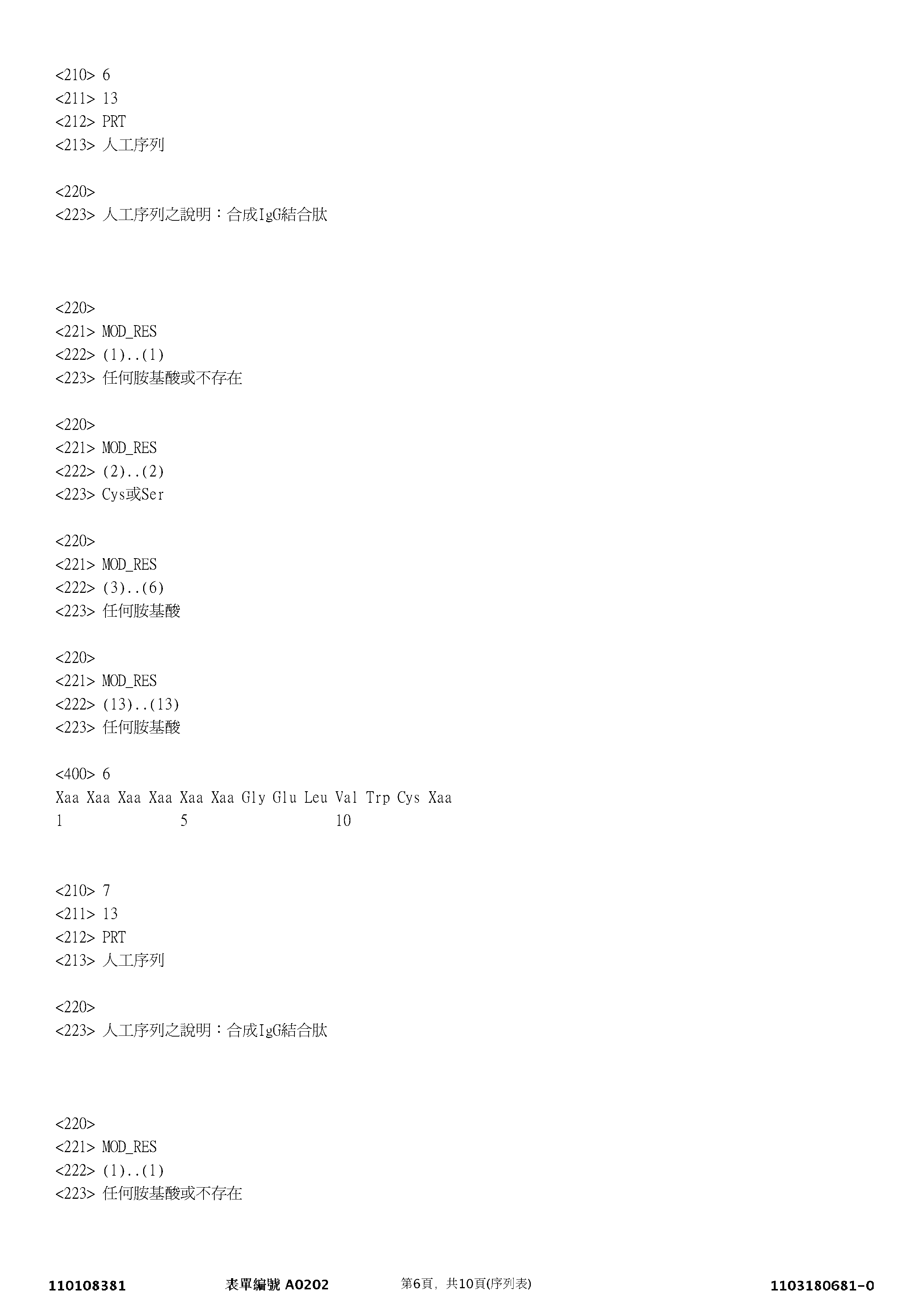


100:微流體裝置 100: Microfluidic Devices
102:殼體 102: Shell
104:支撐結構 104: Support Structure
106:流道 106: runner
107:孔口 107: Orifice
108:微流體迴路結構 108: Microfluidic Circuit Structure
109:內表面 109: inner surface
110:蓋板 110: Cover
114:框 114: Box
116:微流體迴路材料 116: Microfluidic Circuit Materials
120:微流體迴路 120: Microfluidic Circuits
122:通道 122: channel
124:腔室 124: Chamber
126:腔室 126: Chamber
128:腔室 128: Chamber
130:腔室 130: Chamber
132:捕捉器 132: Catcher
134:側通道 134: Side channel
150:系統 150: System
152:控制及偵測裝備 152: Control and detection equipment
154:主控制器 154: Main Controller
156:控制模組 156: Control Module
158:數位記憶體 158: digital memory
160:介質模組 160: Media Module
162:動力模組 162: Power Module
164:成像模組 164: Imaging module
166:傾斜模組 166: Tilt Module
168:其他模組 168: Other mods
170:顯示裝置 170: Display device
172:輸入/輸出裝置 172: Input/Output Devices
178:介質源 178: Media Source
180:流體介質 180: fluid medium
190:傾斜裝置 190: Tilt device
192:電源 192: Power
202:區域 202: Area
Claims (54)
Applications Claiming Priority (2)
| Application Number | Priority Date | Filing Date | Title |
|---|---|---|---|
| US202062986786P | 2020-03-09 | 2020-03-09 | |
| US62/986,786 | 2020-03-09 |
Publications (1)
| Publication Number | Publication Date |
|---|---|
| TW202201008A true TW202201008A (en) | 2022-01-01 |
Family
ID=77670840
Family Applications (1)
| Application Number | Title | Priority Date | Filing Date |
|---|---|---|---|
| TW110108381A TW202201008A (en) | 2020-03-09 | 2021-03-09 | Methods, systems and kits for in-pen assays |
Country Status (10)
| Country | Link |
|---|---|
| US (2) | US12504433B2 (en) |
| EP (1) | EP4118438A4 (en) |
| JP (1) | JP2023517583A (en) |
| KR (1) | KR20220166788A (en) |
| CN (1) | CN115516318A (en) |
| AU (1) | AU2021235901A1 (en) |
| CA (1) | CA3170874A1 (en) |
| IL (1) | IL296312A (en) |
| TW (1) | TW202201008A (en) |
| WO (1) | WO2021183458A2 (en) |
Cited By (1)
| Publication number | Priority date | Publication date | Assignee | Title |
|---|---|---|---|---|
| TWI863309B (en) * | 2023-05-26 | 2024-11-21 | 中原大學 | Devices and methods for producing near-infrared-ii contrast agent |
Families Citing this family (2)
| Publication number | Priority date | Publication date | Assignee | Title |
|---|---|---|---|---|
| EP4465023A1 (en) * | 2023-05-11 | 2024-11-20 | ARKRAY, Inc. | Measurement method and measurement system |
| TWI909490B (en) * | 2024-06-14 | 2025-12-21 | 臺北醫學大學 | Organ chip assembly for simulating physiological barrier environment, microfluidic apparatus and method for simulating a physiological barrier environment |
Family Cites Families (22)
| Publication number | Priority date | Publication date | Assignee | Title |
|---|---|---|---|---|
| US6294063B1 (en) | 1999-02-12 | 2001-09-25 | Board Of Regents, The University Of Texas System | Method and apparatus for programmable fluidic processing |
| US6942776B2 (en) | 1999-05-18 | 2005-09-13 | Silicon Biosystems S.R.L. | Method and apparatus for the manipulation of particles by means of dielectrophoresis |
| US7601270B1 (en) | 1999-06-28 | 2009-10-13 | California Institute Of Technology | Microfabricated elastomeric valve and pump systems |
| EP1240337B1 (en) | 1999-12-24 | 2006-08-23 | Genentech, Inc. | Methods and compositions for prolonging elimination half-times of bioactive compounds |
| US6958132B2 (en) | 2002-05-31 | 2005-10-25 | The Regents Of The University Of California | Systems and methods for optical actuation of microfluidics based on opto-electrowetting |
| WO2005100541A2 (en) | 2004-04-12 | 2005-10-27 | The Regents Of The University Of California | Optoelectronic tweezers for microparticle and cell manipulation |
| JP4951752B2 (en) * | 2005-11-17 | 2012-06-13 | 国立大学法人高知大学 | Mobility normalization device, normalization method, normalization program and self-organizing map, and substance detection method, detection program, detection rule generation method and data structure |
| WO2008091848A2 (en) | 2007-01-22 | 2008-07-31 | Advanced Liquid Logic, Inc. | Surface assisted fluid loading and droplet dispensing |
| WO2008119066A1 (en) | 2007-03-28 | 2008-10-02 | The Regents Of The University Of California | Single-sided lateral-field and phototransistor-based optoelectronic tweezers |
| US9533306B2 (en) | 2010-08-02 | 2017-01-03 | The Regents Of The University Of California | Single sided continuous optoelectrowetting (SCEOW) device for droplet manipulation with light patterns |
| US9227200B2 (en) | 2011-06-03 | 2016-01-05 | The Regents Of The University Of California | Microfluidic devices with flexible optically transparent electrodes |
| US9857333B2 (en) | 2012-10-31 | 2018-01-02 | Berkeley Lights, Inc. | Pens for biological micro-objects |
| US9403172B2 (en) | 2012-11-08 | 2016-08-02 | Berkeley Lights, Inc. | Circuit based optoelectronic tweezers |
| EP3760703A1 (en) | 2013-10-22 | 2021-01-06 | Berkeley Lights, Inc. | Microfluidic devices having isolation pens and methods of testing biological micro-objects with same |
| US9889445B2 (en) | 2013-10-22 | 2018-02-13 | Berkeley Lights, Inc. | Micro-fluidic devices for assaying biological activity |
| EP3134739B1 (en) | 2014-04-25 | 2019-07-10 | Berkeley Lights, Inc. | Providing dep manipulation devices and controllable electrowetting devices in the same microfluidic apparatus |
| US20150306598A1 (en) | 2014-04-25 | 2015-10-29 | Berkeley Lights, Inc. | DEP Force Control And Electrowetting Control In Different Sections Of The Same Microfluidic Apparatus |
| US20150306599A1 (en) | 2014-04-25 | 2015-10-29 | Berkeley Lights, Inc. | Providing DEP Manipulation Devices And Controllable Electrowetting Devices In The Same Microfluidic Apparatus |
| EP3230718B1 (en) * | 2014-12-09 | 2022-03-02 | Berkeley Lights, Inc. | Automated detection of assay-positive areas or of analyte quantities in microfluidic devices |
| CN107427315A (en) * | 2015-03-04 | 2017-12-01 | 伯克利照明有限公司 | The reproduction and selection of embryo in vitro |
| EP4684881A3 (en) * | 2016-04-15 | 2026-03-18 | Bruker Cellular Analysis, Inc. | Methods, systems, computer program and non-transitory computer-readable medium for in-pen assays |
| EP3721209B1 (en) * | 2017-10-15 | 2024-02-07 | Berkeley Lights, Inc. | Methods for in-pen assays |
-
2021
- 2021-03-08 KR KR1020227032070A patent/KR20220166788A/en not_active Withdrawn
- 2021-03-08 EP EP21768399.4A patent/EP4118438A4/en active Pending
- 2021-03-08 IL IL296312A patent/IL296312A/en unknown
- 2021-03-08 CA CA3170874A patent/CA3170874A1/en active Pending
- 2021-03-08 WO PCT/US2021/021417 patent/WO2021183458A2/en not_active Ceased
- 2021-03-08 AU AU2021235901A patent/AU2021235901A1/en not_active Abandoned
- 2021-03-08 CN CN202180033790.1A patent/CN115516318A/en active Pending
- 2021-03-08 JP JP2022554321A patent/JP2023517583A/en active Pending
- 2021-03-09 TW TW110108381A patent/TW202201008A/en unknown
-
2022
- 2022-09-08 US US17/930,712 patent/US12504433B2/en active Active
-
2025
- 2025-08-19 US US19/304,334 patent/US20260056208A1/en active Pending
Cited By (1)
| Publication number | Priority date | Publication date | Assignee | Title |
|---|---|---|---|---|
| TWI863309B (en) * | 2023-05-26 | 2024-11-21 | 中原大學 | Devices and methods for producing near-infrared-ii contrast agent |
Also Published As
| Publication number | Publication date |
|---|---|
| JP2023517583A (en) | 2023-04-26 |
| AU2021235901A1 (en) | 2022-10-06 |
| CA3170874A1 (en) | 2021-09-16 |
| KR20220166788A (en) | 2022-12-19 |
| WO2021183458A2 (en) | 2021-09-16 |
| CN115516318A (en) | 2022-12-23 |
| US20230251268A1 (en) | 2023-08-10 |
| IL296312A (en) | 2022-11-01 |
| WO2021183458A3 (en) | 2021-11-18 |
| US12504433B2 (en) | 2025-12-23 |
| EP4118438A2 (en) | 2023-01-18 |
| EP4118438A4 (en) | 2024-02-28 |
| US20260056208A1 (en) | 2026-02-26 |
Similar Documents
| Publication | Publication Date | Title |
|---|---|---|
| AU2022286586B2 (en) | Methods, systems and kits for in-pen assays | |
| US11789016B2 (en) | Methods, systems and kits for in-pen assays | |
| US12345701B2 (en) | Methods for assaying biological cells in a microfluidic device | |
| US20260056208A1 (en) | Methods, Systems and Kits for In-Pen Assays | |
| US20240302378A1 (en) | Methods of Microfluidic Assay and Bioproduction from Non-Mammalian Cells and Kits Therefor | |
| US20240318120A1 (en) | Apparatuses, methods, and kits for microfluidic assays | |
| US20240288442A1 (en) | Methods of assaying biomolecules within a microfluidic device | |
| HK40005230B (en) | Methods, systems and kits for in-pen assays | |
| HK40005230A (en) | Methods, systems and kits for in-pen assays |