TWI853627B - Ball Screw Actuator - Google Patents
Ball Screw Actuator Download PDFInfo
- Publication number
- TWI853627B TWI853627B TW112124281A TW112124281A TWI853627B TW I853627 B TWI853627 B TW I853627B TW 112124281 A TW112124281 A TW 112124281A TW 112124281 A TW112124281 A TW 112124281A TW I853627 B TWI853627 B TW I853627B
- Authority
- TW
- Taiwan
- Prior art keywords
- passage
- lubricating oil
- return
- ball
- ball screw
- Prior art date
Links
Images


Classifications
-
- F—MECHANICAL ENGINEERING; LIGHTING; HEATING; WEAPONS; BLASTING
- F16—ENGINEERING ELEMENTS AND UNITS; GENERAL MEASURES FOR PRODUCING AND MAINTAINING EFFECTIVE FUNCTIONING OF MACHINES OR INSTALLATIONS; THERMAL INSULATION IN GENERAL
- F16C—SHAFTS; FLEXIBLE SHAFTS; ELEMENTS OR CRANKSHAFT MECHANISMS; ROTARY BODIES OTHER THAN GEARING ELEMENTS; BEARINGS
- F16C29/00—Bearings for parts moving only linearly
- F16C29/04—Ball or roller bearings
- F16C29/06—Ball or roller bearings in which the rolling bodies circulate partly without carrying load
-
- F—MECHANICAL ENGINEERING; LIGHTING; HEATING; WEAPONS; BLASTING
- F16—ENGINEERING ELEMENTS AND UNITS; GENERAL MEASURES FOR PRODUCING AND MAINTAINING EFFECTIVE FUNCTIONING OF MACHINES OR INSTALLATIONS; THERMAL INSULATION IN GENERAL
- F16H—GEARING
- F16H25/00—Gearings comprising primarily only cams, cam-followers and screw-and-nut mechanisms
- F16H25/18—Gearings comprising primarily only cams, cam-followers and screw-and-nut mechanisms for conveying or interconverting oscillating or reciprocating motions
- F16H25/20—Screw mechanisms
- F16H25/24—Elements essential to such mechanisms, e.g. screws, nuts
Landscapes
- Engineering & Computer Science (AREA)
- General Engineering & Computer Science (AREA)
- Mechanical Engineering (AREA)
- Transmission Devices (AREA)
Abstract
[課題]進行成即使潤滑油注入通路相對於貫通孔偏向左右的其中一側而設置,仍然可將潤滑油均等地供給至相對於貫通孔呈左右對稱之返回通路。 [解決手段]本發明具有:潤滑油注入通路42,相對於滾珠螺桿軸102所貫通之貫通孔31偏向左右的其中一側而設置;及潤滑油供給通路44,將潤滑油從潤滑油注入通路42供給至左右的線性滾珠軸承70的返回通路40,潤滑油供給通路44具有:第1通路48,從潤滑油注入通路42到達通過貫通孔31的中心之左右對稱線A上的分歧位置B;及左右對稱的第2通路50、52,從分歧位置B朝左右分歧而到達左右的返回通路40。 [Topic] Even if the lubricating oil injection passage is set to one side of the through hole, the lubricating oil can still be evenly supplied to the return passage that is symmetrical to the left and right of the through hole. [Solution] The present invention comprises: a lubricating oil injection passage 42, which is arranged to one side of the through hole 31 through which the ball screw shaft 102 passes; and a lubricating oil supply passage 44, which supplies lubricating oil from the lubricating oil injection passage 42 to the return passage 40 of the left and right linear ball bearings 70, and the lubricating oil supply passage 44 comprises: a first passage 48, which reaches the divergence position B on the left-right symmetric line A passing through the center of the through hole 31 from the lubricating oil injection passage 42; and left-right symmetric second passages 50, 52, which diverge from the divergence position B to the left and right and reach the left and right return passages 40.
Description
本發明是有關於一種滾珠螺桿致動器,更詳細而言,是有關於一種對已組入滾珠螺桿致動器的線性滾珠軸承(linear ball bearing)之潤滑油供給構造。The present invention relates to a ball screw actuator, and more particularly, to a lubricating oil supply structure for a linear ball bearing incorporated in the ball screw actuator.
作為直線運動致動器,已知有一種滾珠螺桿致動器,前述滾珠螺桿致動器具有:直線狀的導軌,具有左右的側壁且具有凹形剖面形狀;滑件,配置於導軌的左右側壁之間;左右的線性滾珠軸承,具備在導軌的左右的側壁與滑件之間循環的複數個滾珠,且引導滑件對導軌之軸線方向的移動;滾珠螺桿螺帽部,設置於滑件;及滾珠螺桿軸,在軸線方向上貫通於已在滑件中設置於左右方向的中央之貫通孔,且透過滾珠螺合於已設在前述滑件之滾珠螺桿螺帽部(例如專利文獻1)。設在此滾珠螺桿致動器的滑件具有:滑件本體,保持滾珠螺桿螺帽部;及滾珠返回構件,安裝於滑件本體的軸線方向的兩端且具備有左右的線性滾珠軸承的返回通路。As a linear motion actuator, there is a known ball screw actuator, which comprises: a linear guide rail having left and right side walls and a concave cross-sectional shape; a slide member disposed between the left and right side walls of the guide rail; left and right linear ball bearings having a plurality of balls circulating between the left and right side walls of the guide rail and the slide member and guiding the axial movement of the slide member with respect to the guide rail; a ball screw nut portion disposed on the slide member; and a ball screw shaft axially penetrating a through hole disposed in the center of the slide member in the left and right directions and being threadedly engaged with the ball screw nut portion disposed on the slide member through the ball (e.g., Patent Document 1). The slider provided in the ball screw actuator includes: a slider body holding a ball screw nut portion; and a ball return member mounted on both ends of the slider body in the axial direction and having a return passage of a left and right linear ball bearing.
對上述之滾珠螺桿致動器的左右的線性滾珠軸承供給潤滑脂(grease)等的潤滑油之構造,包含設置在滾珠返回構件之潤滑油注入通路、以及從潤滑油注入通路對左右的線性滾珠軸承的返回通路(以下,有時會稱為左右的返回通路)供給潤滑油之潤滑油供給通路。 先前技術文獻 專利文獻 The structure for supplying lubricating oil such as grease to the left and right linear ball bearings of the above-mentioned ball screw actuator includes a lubricating oil injection passage provided in the ball return member, and a lubricating oil supply passage for supplying lubricating oil from the lubricating oil injection passage to the return passages of the left and right linear ball bearings (hereinafter sometimes referred to as left and right return passages). Prior art literature Patent literature
專利文獻1:日本特開平4-115842號公報Patent document 1: Japanese Patent Application Publication No. 4-115842
發明欲解決之課題Invention Problems to be Solved
為了將滾珠螺桿致動器的左右的線性滾珠軸承的潤滑進行成互相均等,必須將潤滑油互相均等地供給至左右的返回通路。In order to equally lubricate the left and right linear ball bearings of the ball screw actuator, lubricating oil must be equally supplied to the left and right return passages.
左右的線性滾珠軸承由於相對於滾珠螺桿軸所貫通之貫通孔呈左右對稱地設置,所以只要使在軸線方向上延伸之潤滑油注入通路在通過貫通孔的中心之左右對稱線上,藉由將左右的返回通路相對於貫通孔設置成左右對稱,亦即,只要從潤滑油注入通路至到達返回通路之通路長度在左右的返回通路中為相同,潤滑油即可互相均等地被供給至左右的返回通路。Since the left and right linear ball bearings are disposed symmetrically with respect to the through hole through which the ball screw shaft passes, the lubricating oil injection passage extending in the axial direction can be disposed on a symmetrical line passing through the center of the through hole. By disposing the left and right return passages symmetrically with respect to the through hole, that is, as long as the passage length from the lubricating oil injection passage to the return passage is the same in the left and right return passages, the lubricating oil can be equally supplied to the left and right return passages.
但是,若將潤滑油注入通路設置於通過貫通孔的中心之左右對稱線上,滑件的上下方向的外形尺寸(參照圖5的高度尺寸H)會成為比貫通孔的直徑與潤滑油注入通路的直徑之和更大之尺寸,而變得難以謀求滑件的上下方向的小型化(downsizing)。However, if the lubricating oil injection passage is set on the left-right symmetry line passing through the center of the through hole, the outer dimensions of the slider in the vertical direction (refer to the height dimension H in Figure 5) will become larger than the sum of the diameter of the through hole and the diameter of the lubricating oil injection passage, making it difficult to achieve miniaturization (downsizing) of the slider in the vertical direction.
若潤滑油注入通路是設置成相對於貫通孔而偏向左右的其中一側,滑件的上下方向的外形尺寸便可以設成和貫通孔的直徑與潤滑油注入通路的直徑之和相等或在其以下,而可以謀求滑件的上下方向的小型化。但是,在此情況下,由潤滑油注入通路至到達返回通路之通路長度在左右的返回通路中不會成為相同,而變得難以將潤滑油互相均等地供給至左右的返回通路。If the lubricating oil injection passage is provided to be biased to one side of the through hole, the outer dimensions of the slider in the vertical direction can be set equal to or less than the sum of the diameter of the through hole and the diameter of the lubricating oil injection passage, and the slider can be miniaturized in the vertical direction. However, in this case, the length of the passage from the lubricating oil injection passage to the return passage will not be the same in the left and right return passages, making it difficult to supply the lubricating oil to the left and right return passages equally.
本發明欲解決之課題在於:即使潤滑油注入通路是相對於貫通孔偏向左右的其中一側而設置,仍然可將潤滑油均等地供給至左右的線性滾珠軸承。 用以解決課題之手段 The problem that the present invention aims to solve is that even if the lubricating oil injection passage is set to one side of the through hole, the lubricating oil can still be evenly supplied to the left and right linear ball bearings. Means for solving the problem
為了解決上述課題,本發明的某個態樣是一種滾珠螺桿致動器,具有:導軌,呈直線狀,具有左右的側壁且具有凹形剖面形狀;滑件,配置於前述導軌的前述左右的側壁之間;左右的線性滾珠軸承,具備在前述導軌的前述左右的側壁與前述滑件之間循環的複數個滾珠,且引導前述滑件對前述導軌之軸線方向的移動;滾珠螺桿螺帽部,設置於前述滑件;及滾珠螺桿軸,在軸線方向上貫通於已設置在前述滑件之貫通孔,並且透過滾珠螺合於已設置在前述滑件之前述滾珠螺桿螺帽部, 前述滑件具有:滑件本體,包含前述滾珠螺桿螺帽部;及滾珠返回構件,分別安裝於前述滑件本體的軸線方向的兩端, 前述滾珠返回構件的至少其中一者具有:左右的返回通路,相對於前述貫通孔而呈左右對稱地設置且供前述左右的線性滾珠軸承的各個滾珠移動;潤滑油注入通路,相對於前述貫通孔偏向左右的其中一側而設置;及潤滑油供給通路,將潤滑油從前述潤滑油注入通路供給至前述左右的返回通路, 前述潤滑油供給通路具有:第1通路,從前述潤滑油注入通路到達通過前述貫通孔的中心之左右對稱線上的分歧位置;及左右對稱的第2通路,從前述分歧位置朝左右分歧而到達前述左右的返回通路。 In order to solve the above-mentioned problem, one aspect of the present invention is a ball screw actuator, which has: a guide rail, which is in a straight line shape, has left and right side walls and has a concave cross-sectional shape; a slider, which is arranged between the left and right side walls of the guide rail; left and right linear ball bearings, which have a plurality of balls circulating between the left and right side walls of the guide rail and the slider, and guide the slider to move in the axial direction of the guide rail; a ball screw nut portion, which is arranged on the slider; and a ball screw shaft, which penetrates the through hole arranged on the slider in the axial direction, and is screwed to the ball screw nut portion arranged on the slider through the ball, The aforementioned slider comprises: a slider body including the aforementioned ball screw nut portion; and a ball return member, which is respectively mounted at both ends of the aforementioned slider body in the axial direction. At least one of the aforementioned ball return members comprises: left and right return passages, which are arranged symmetrically with respect to the aforementioned through hole and for each ball of the aforementioned left and right linear ball bearing to move; a lubricating oil injection passage, which is arranged on one side of the left and right relative to the aforementioned through hole; and a lubricating oil supply passage, which supplies lubricating oil from the aforementioned lubricating oil injection passage to the aforementioned left and right return passages. The lubricating oil supply passage comprises: a first passage extending from the lubricating oil injection passage to a diverging position on a left-right symmetric line passing through the center of the through hole; and a left-right symmetric second passage extending from the diverging position to the left and right to the left and right return passages.
根據此態樣,即使潤滑油注入通路是相對於貫通孔偏向左右的其中一側而設置,仍然可均等地對左右的線性滾珠軸承(返回通路)進行供給。According to this aspect, even if the lubricating oil injection passage is provided to one of the left and right sides with respect to the through hole, the lubricating oil can be evenly supplied to the left and right linear ball bearings (return passages).
在上述態樣中,較佳的是,亦可為:前述左右的線性滾珠軸承分別具有:外部通路,形成在前述導軌的對應之前述側壁與前述滑件本體之間;及內部通路,在前述滑件本體的內部於軸線方向上延伸形成, 前述左右的返回通路分別具有:外側端部,連通於所對應之前述外部通路;及內側端部,連通於對應之前述內部通路, 前述第2通路是連通於前述左右的返回通路中的比前述內側端部更靠近前述外側端部之側的部位。 In the above aspect, it is preferred that: the aforementioned left and right linear ball bearings respectively have: an external passage formed between the corresponding aforementioned side wall of the aforementioned guide rail and the aforementioned slider body; and an internal passage extending in the axial direction inside the aforementioned slider body, The aforementioned left and right return passages respectively have: an outer end connected to the corresponding aforementioned external passage; and an inner end connected to the corresponding aforementioned internal passage, The aforementioned second passage is connected to a portion of the aforementioned left and right return passages that is closer to the side of the aforementioned outer end than the aforementioned inner end.
根據此態樣,可在不使潤滑油的供給壓力變高的情形下使潤滑油對返回通路之供給順暢地進行。According to this aspect, the lubricating oil can be smoothly supplied to the return passage without increasing the supply pressure of the lubricating oil.
在上述態樣中,較佳的是,亦可為:前述第2通路是連通於前述左右的返回通路中的前述外側端部。In the above aspect, it is also preferable that: the second passage is connected to the outer end portions of the left and right return passages.
根據此態樣,可在不使潤滑油對返回通路之供給壓力變高的情形下更加順暢地進行。According to this aspect, the operation can be performed more smoothly without increasing the supply pressure of the lubricating oil to the return passage.
在上述態樣中,較佳的是,亦可為:前述第1通路與前述第2通路包含在前述軸線方向的前後互相重疊之部分,且該互相重疊之部分的前述第1通路與前述第2通路是被已設置在前述滾珠返回構件的分隔壁隔離。In the above aspect, it is also preferable that: the first passage and the second passage include overlapping portions in the front and rear of the axial direction, and the first passage and the second passage in the overlapping portions are separated by a partition wall provided in the ball return member.
根據此態樣,第1通路與第2通路在軸線方向的前後互相重疊之部分可在不互相干涉的情形下構成。According to this aspect, the first passage and the second passage can be formed without interfering with each other in the front and rear overlapping portions in the axial direction.
在上述態樣中,較佳的是,亦可為:前述分隔壁是藉由安裝於前述滾珠返回構件的分隔壁構件而構成。In the above aspect, it is also preferred that: the aforementioned partition wall is formed by a partition wall component installed on the aforementioned ball return component.
根據此態樣,分隔壁的形成會變得容易。According to this aspect, the formation of the partition wall becomes easy.
在上述態樣中,較佳的是,亦可為:前述潤滑油供給通路更具有:第3通路,從前述第2通路的各個呈左右對稱地在前述貫通孔的徑向方向外側延伸;及第4通路,從前述第3通路到達前述貫通孔。In the above aspect, it is also preferable that the lubricating oil supply passage further comprises: a third passage extending from each of the second passages symmetrically on the radial outer side of the through hole; and a fourth passage extending from the third passage to the through hole.
根據此態樣,亦可從貫通孔對滾珠螺桿軸進行潤滑油的供給。According to this aspect, lubricating oil can also be supplied to the ball screw shaft through the through hole.
在上述態樣中,較佳的是,亦可為:前述第1通路、前述第2通路、前述第3通路以及前述第4通路包含藉由凹溝所構成之部分,前述凹溝是在前述滾珠返回構件抵接於前述滑件本體的端面之表面呈開口的溝,且凹溝界定出藉由前述滑件本體的前述端面封閉開口之前述潤滑油供給通路。In the above aspect, it is preferable that: the aforementioned first passage, the aforementioned second passage, the aforementioned third passage and the aforementioned fourth passage include a portion formed by a groove, and the aforementioned groove is an open groove on the surface of the end face of the aforementioned ball return member abutting against the aforementioned sliding body, and the groove defines the lubricating oil supply passage before the opening is closed by the aforementioned end face of the aforementioned sliding body.
根據此態樣,具有閉合剖面形狀之潤滑油供給通路會具有較高自由度且容易地形成。According to this aspect, the lubricating oil supply passage having a closed cross-sectional shape can be easily formed with a high degree of freedom.
在上述態樣中,較佳的是,亦可為:前述第1通路與前述第2通路包含在前述軸線方向的前後互相重疊之部分,該互相重疊之部分的前述第1通路與前述第2通路是被已安裝在前述滾珠返回構件之分隔壁構件隔離,且部分是藉由設置於前述分隔壁構件之凹溝來構成。In the above aspect, it is preferable that: the aforementioned first passage and the aforementioned second passage include overlapping portions in front and back of the aforementioned axial direction, and the aforementioned first passage and the aforementioned second passage of the overlapping portion are separated by a partition wall member installed on the aforementioned ball return member, and partly formed by a groove arranged in the aforementioned partition wall member.
根據此態樣,第2通路和第1通路重疊之部分可在不和第1通路干涉的情形下容易地形成。According to this aspect, the portion where the second via overlaps the first via can be easily formed without interfering with the first via.
在上述態樣中,較佳的是,亦可為:具有配置在前述滑件本體與前述滾珠返回構件的各個之間的密封板,且前述密封板的各個具有內徑比前述貫通孔更小的開口。In the above aspect, it is also preferable that: a sealing plate is arranged between the aforementioned slider body and each of the aforementioned ball return components, and each of the aforementioned sealing plates has an opening with an inner diameter smaller than the aforementioned through hole.
根據此態樣,可抑制已供給至滾珠返回構件的貫通孔之潤滑油過剩地朝滑件本體側流動之情形。According to this aspect, it is possible to suppress the lubricating oil supplied to the through hole of the ball return member from excessively flowing toward the slider body side.
在上述態樣中,較佳的是,亦可為:前述左右的線性滾珠軸承分別構成為上下2層,前述滾珠返回構件在上下2層具有返回通路,前述第2通路是呈左右對稱地到達前述上下2層的返回通路間,並連通於前述上下2層的返回通路。In the above aspect, it is preferable that: the aforementioned left and right linear ball bearings are respectively constituted into two layers, the aforementioned ball return component has a return passage in the upper and lower layers, and the aforementioned second passage is symmetrically extended between the return passages of the upper and lower layers and connected to the return passages of the upper and lower layers.
根據此態樣,即使潤滑油注入通路相對於貫通孔而偏向左右方向的單側,仍可將潤滑油對左右的上下2層的線性滾珠軸承之供給以上下均等以及左右均等的方式來進行。 發明效果 According to this aspect, even if the lubricating oil injection passage is biased toward one side in the left-right direction relative to the through hole, the lubricating oil can still be supplied to the upper and lower two-layer linear ball bearings on the left and right sides in an even manner. Effect of the invention
根據本發明之滾珠螺桿致動器,即使潤滑油注入通路是相對於貫通孔偏向左右的其中一側而設置,仍然可將潤滑油均等地供給至左右的線性滾珠軸承。According to the ball screw actuator of the present invention, even if the lubricating oil injection passage is arranged to one side of the through hole, the lubricating oil can still be evenly supplied to the left and right linear ball bearings.
用以實施發明之形態The form used to implement the invention
參照附加圖式來說明本發明之較佳的實施形態。The preferred embodiments of the present invention will be described with reference to the attached drawings.
(實施形態1)(Implementation form 1)
參照圖1~圖7,針對實施形態1之滾珠螺桿致動器10來說明。再者,圖7是顯示線性滾珠軸承的滾珠循環路徑以及潤滑油通路的概要之概略圖,且是將後述之滑件30以及側壁22的圖示省略。1 to 7 , the
實施形態1之滾珠螺桿致動器10是如圖1所示,且具有:導軌20,呈直線狀,具有左右的側壁22且具有凹形剖面形狀;滑件30,配置於導軌20的左右側壁22之間;與左右的線性滾珠軸承70,具備在導軌20的左右的側壁22與滑件30之間循環的複數個滾珠72(參照圖7),且引導滑件30對導軌20之軸線方向的移動。The
滾珠螺桿致動器10更具有:滾珠螺桿螺帽部100,設置在滑件30;及滾珠螺桿軸102,在軸線方向上貫通於已設置在滑件30之貫通孔31,且透過滾珠104(參照圖6)螺合於已設置在滑件30的滾珠螺桿螺帽部100。滾珠螺桿軸102是被已安裝於導軌20的軸端之未圖示的電動馬達旋轉驅動。再者,滾珠螺桿螺帽部100亦可和滑件30為一體構造。The
滑件30具有:包含滾珠螺桿螺帽部100之大致長方體形狀的滑件本體32、與藉由複數個螺栓34而固定於滑件本體32的軸線方向的兩端(前後端)之大致長方體形狀的前後的滾珠返回構件36。The
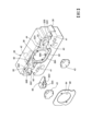
如圖2以及圖5所示,各個滾珠返回構件36具有在軸線方向上貫通大致中央部且構成上述之貫通孔31的一部分之貫通孔38。如圖6所示,貫通孔38具有和貫通孔31當中的滑件本體32的貫通之部分的貫通孔31A大致相同或更小之內徑,且呈和貫通孔31A在大致同軸上(大致同心)地設置。As shown in Fig. 2 and Fig. 5, each
各個滾珠返回構件36更具有:左右的返回通路40,相對於貫通孔38呈左右對稱地設置,且供左右的線性滾珠軸承70的各個滾珠72可滾動地移動;潤滑油注入通路42,在軸線方向上延伸,且相對於貫通孔38偏向左右的其中一側而設置;與潤滑油供給通路44,將潤滑脂等的潤滑油從潤滑油注入通路42供給至左右的返回通路40。在各個滾珠返回構件36的外壁安裝有連通於對應之潤滑油注入通路42的潤滑油油嘴46(參照圖1及圖7)。Each
左右的線性滾珠軸承70是如之後詳述之圖7所示,分別具有:外部通路74,在導軌20的對應之側壁22(參照圖1)與滑件本體32(參照圖1)之間朝軸線方向延伸形成;與內部通路76,在滑件本體32(參照圖1)的內部於軸線方向上延伸(貫通)形成。各個外部通路74是藉由形成於側壁22的內側面之大致半圓形剖面的凹溝24(參照圖1)、與形成於滑件本體32的外側面之大致半圓形剖面的凹溝(未圖示)而形成。側壁22的內側面與滑件本體32的外側面為非接觸,且在側壁22的內側面與滑件本體32的外側面之間形成有在左右方向上具有間隙寬度且在軸線方向上延伸之氣隙(air gap)G(參照圖5)。As shown in FIG. 7 described in detail later, the left and right
左右的返回通路40是如圖2以及圖5所示,分別為藉由凹溝41與通路界定構件43所界定出之滾珠72可滾動之平面形狀為大致半圓形(U字形)的通路,前述凹溝41形成於滾珠返回構件36且具有大致半圓形的平面形狀,前述通路界定構件43安裝於滾珠返回構件36且具有大致半圓形的平面形狀。各個返回通路40具有連通於所對應之外部通路74的外側端部40A、以及連通於所對應之內部通路76的內側端部40B。As shown in FIG. 2 and FIG. 5 , the left and
在各個滾珠返回構件36中,具有大致半圓形的橫剖面形狀的滾珠脫落防止部39是從左右的外壁各自朝向外側而突出形成,前述滾珠脫落防止部39是用於防止線性滾珠軸承70的滾珠72從左右的返回通路40的外側端部40A的各個朝外側脫落之情形。In each
左右的線性滾珠軸承70是分別藉由互相連通之外部通路74、內部通路76以及前後的返回通路40,而構成供複數個滾珠72循環之由閉迴路所形成的循環路。The left and right
在圖5以及圖7中觀看,潤滑油供給通路44具有:第1通路48,從潤滑油注入通路42朝右方延伸而到達通過貫通孔38的中心且朝上下方向延伸之左右對稱線A上的分歧位置B;與左右對稱的左側第2通路50以及右側第2通路52,從分歧位置B朝左右分歧而到達左右的返回通路40。As seen in Figures 5 and 7, the lubricating
左側第2通路50具有從分歧位置B朝左方延伸之左方延伸部50A、與從左方延伸部50A的左端朝下方傾斜地彎折而到達左側的返回通路40之傾斜延伸部50B。傾斜延伸部50B包含連通端50C,前述連通端50C是和返回通路40中的左側的外側端部40A的附近之部位連通。The left
連通端50C在左側的返回通路40中,只要在比在內側端部40B與外側端部40A之間分成2等分之位置更靠近外側端部40A之側的位置形成開口即可。連通端50C較佳的是如在圖5藉由假想線所示地連通於最接近左側的外部通路74的氣隙G之左側的外側端部40A的返回通路40。The connecting
右側第2通路52具有從分歧位置B朝右方延伸之右方延伸部52A、與從右方延伸部52A的右端朝下方傾斜彎折而到達右側的返回通路40之傾斜延伸部52B。傾斜延伸部52B包含連通端52C,前述連通端52C是和右側的外側端部40A附近的返回通路40連通。The right
連通端52C在右側的返回通路40中,只要在比在內側端部40B與外側端部40A之間分成2等分之位置更靠近外側端部40A的位置形成開口即可。連通端52C較佳的是如在圖5藉由假想線所示地連通於最接近右側的外部通路74的氣隙G之右側的外側端部40A的返回通路40。The connecting
左側第2通路50與右側第2通路52是相對於左右對稱線A而呈左右對稱,且各個的通路長度互相相等。The left
潤滑油供給通路44更具有從左側第2通路50以及右側第2通路52在貫通孔38的徑向方向外側呈左右對稱地朝上下方向延伸之左側第3通路54及右側第3通路56、與朝左右方向延伸而將左側第3通路54以及右側第3通路56的下端互相連接之第4通路58。第4通路58包含朝向貫通孔38的下部呈開口之開口端58A,且到達貫通孔38。The lubricating
第1通路48、左側第2通路50、右側第2通路52、左側第3通路54、右側第3通路56以及第4通路58包含藉由在滾珠返回構件36中的接合於滑件本體32的端面之表面開口之凹溝所構成之部分。該凹溝是藉由滑件本體32的端面將開口封閉,藉此界定出具有閉合剖面形狀之潤滑油供給通路。藉此,自由度較高之潤滑油供給通路的構成會變得較容易。The
第1通路48與左側第2通路50的左方延伸部50A包含在軸線方向的前後互相重疊之部分。此第1通路48與左側第2通路50的左方延伸部50A互相重疊之部分,是藉由嵌合裝設於已形成在滾珠返回構件36的凹部62(參照圖3)之分隔壁構件60(參照圖4)而被儘可能地隔離成個別的通路。The
說明此隔離構造之詳細內容。如圖3所示,滾珠返回構件36的凹部62具有潤滑油注入通路42所開口之深底底面62A、以及形成於深底底面62A的外周的一部分之淺底底面62B。分隔壁構件60是抵接於淺底底面62B,而於分隔壁構件60的背面與深底底面62A之間界定出第1通路48。由深底底面62A所形成之凹部62包含超過分歧位置B(參照圖5)而朝右側延伸之部分,第1通路48也是朝相同方向延伸。由於分隔壁構件60具有右端未超過分歧位置B的左右尺寸,所以第1通路48會在分歧位置B上朝向左側第2通路50以及右側第2通路52的基端開口。The details of this isolation structure are described. As shown in FIG3 , the
左側第2通路50的左方延伸部50A和第1通路48重疊之部分,是如圖4所示地藉由形成於分隔壁構件60的表面之凹溝50D來構成。在分隔壁構件60的表面形成有構成從左側第2通路50分歧之左側第3通路54的分歧端之凹溝54A。The overlapped portion of the
藉由此構成,第1通路48與左側第2通路50的左方延伸部50A在軸線方向上互相重疊之部分不會互相干涉。而且,第1通路48與左側第2通路50的左方延伸部50A在軸線方向上互相重疊之部分的形成,不用使用特殊的工法而變得較容易。With this configuration, the
左側第2通路50、右側第2通路52、左側第3通路54、右側第3通路56以及第4通路58包含互相協同合作而包圍貫通孔38的徑向方向外側之部分。如圖2、圖5以及圖6所示,在滾珠返回構件36中的接合於滑件本體32的端面之表面安裝有密封板64,前述密封板64是覆蓋左側第2通路50、右側第2通路52、左側第3通路54、右側第3通路56以及第4通路58包圍貫通孔38之部分的凹溝的對滑件本體32的前述表面之開口。密封板64具有和貫通孔31(31A、38)大致同心且內徑比貫通孔31更小之開口68。The left
再者,在滾珠返回構件36,於供密封板64安裝之部分形成有具有和密封板64的板厚相同的深度之擱架部36A(參照圖2),藉由密封板64的外周緣部嵌入擱架部36A,滑件本體32接合於滑件本體32的端面之表面包含密封板64的部分而形成為面齊平。Furthermore, in the
根據上述之構成,已注入潤滑油注入通路42之潤滑油是在第1通路48中流動而到達貫通孔38的左右對稱線A上的分歧位置B,且從分歧位置B在左右對稱的左側第2通路50以及右側第2通路52流動,並從連通端50C、52C供給至左右的線性滾珠軸承70的返回通路40。According to the above-mentioned structure, the lubricating oil injected into the lubricating
由於已注入潤滑油注入通路42之潤滑油一旦藉由第1通路48而朝分歧位置B流動,其大部分就會在左右對稱的左側第2通路50以及右側第2通路52中流動而供給至左右的線性滾珠軸承70的返回通路40,所以即使潤滑油注入通路42相對於分歧位置B偏向左右方向的單側,仍然可將來自潤滑油注入通路42之潤滑油均等地供給至左右的線性滾珠軸承70的返回通路40。Once the lubricating oil injected into the lubricating
亦即,左側第2通路50與右側第2通路52是相對於左右對稱線A而呈左右對稱,且由於各個通路的通路長度互相相等,所以即使潤滑油注入通路42相對於分歧位置B偏向左右方向的單側,左右的線性滾珠軸承70之由潤滑油所進行的潤滑仍然可左右均等地進行。That is, the left
相較於潤滑油注入通路42位於分歧位置B之情況,藉由潤滑油注入通路42相對於分歧位置B偏向左右方向的單側之作法,可以將包含滾珠返回構件36在內之滑件30的貫通孔31(31A、38)的上緣與滑件30的上緣(上表面)之間的間隔做得較小。藉此,可以將滑件30的高度尺寸H(參照圖5)做得較小,進而可謀求滾珠螺桿致動器10的上下方向的小型化。Compared to the case where the lubricating
在返回通路40的外側端部40A與內側端部40B中,藉由外側端部40A位於最接近於外部通路74的氣隙G且為大氣開放之側,外側端部40A的潤滑油壓會變得比內側端部40B的潤滑油壓更低。亦即,有關於返回通路40中的潤滑油壓,外側端部40A側相較於內側端部40B側形成為低壓側。Since the
左側第2通路50以及右側第2通路52的對應之對返回通路40的連通端50C、52C,是在返回通路40的比將返回通路40在內側端部40B與外側端部40A之間分成2等分之位置更靠近外側端部40A之側的部位上連通。藉由此左側第2通路50以及右側第2通路52的構造,而將潤滑油供給至潤滑油壓(內部壓力)比內側端部40B低之低壓側的返回通路40。The communication ends 50C and 52C of the left
藉此,和將潤滑油供給至內側端部40B側的返回通路40的情況相較之下,可在不使潤滑油的注入壓力變高的情形下,順暢地進行對返回通路40之潤滑油的供給,而改善潤滑油的供給作業性。Thereby, compared with the case where the lubricating oil is supplied to the
返回通路40中的潤滑油的內部壓力,由於最接近於外部通路74的氣隙G之外側端部40A會變得最低,所以連通端50C、52C是如在圖5藉由假想線所示,為了對返回通路40之潤滑油的順暢的供給,較佳的是連通於外側端部40A。The internal pressure of the lubricating oil in the
左側第2通路50以及右側第2通路52的對應之對返回通路40的連通端50C、52C,藉由在返回通路40的比將返回通路40在內側端部40B與外側端部40A之間分成2等分之位置更靠近外側端部40A之側的部位上連通,而可將潤滑油供給至潤滑油壓(內部壓力)比內側端部40B低之部位的返回通路40。The connecting ends 50C and 52C of the
藉此,相較於對內側端部40B側的返回通路40供給潤滑油的情況,可在不使注入壓力變高的情形下順暢地進行對返回通路40之潤滑油的供給,而改善潤滑油的供給作業性。Thereby, compared with the case where lubricating oil is supplied to the
如在圖5藉由假想線所示,為了和上述之潤滑油的內部壓力有關之順暢的供給,連通端50C、52C宜連通於最接近對應之外部通路74的氣隙G之外側端部40A。As shown by the phantom lines in FIG. 5 , in order to smoothly supply the lubricating oil in relation to the internal pressure mentioned above, the connecting ends 50C, 52C are preferably connected to the outer
已注入潤滑油注入通路42之潤滑油的一部分一旦藉由第1通路48朝分歧位置B流動之後,會在左側第2通路50、右側第2通路52、左側第3通路54、右側第3通路56以及第4通路58中流動,並從開口端58A流出至貫通孔38。Once a portion of the lubricating oil injected into the lubricating
藉此,可將潤滑油塗佈於滾珠螺桿軸102貫通於貫通孔38之部分的外周面,而進行滾珠螺桿軸102的潤滑。Thereby, the lubricating oil can be applied to the outer peripheral surface of the portion of the
如圖6所示,藉由讓密封板64的開口68的內徑比滑件30的貫通孔31A的內徑更小之作法,密封板64會如圖6所示,作為區分貫通孔31A與貫通孔38之擋堰而作用,從第4通路58的開口端58A流出至貫通孔38之潤滑油會變得難以朝貫通孔31A流動。亦即,可抑制已供給至滾珠返回構件36的貫通孔38之潤滑油過剩地朝滑件本體32側流動之情形。藉此,變得難以讓潤滑油超出必要地朝滑件本體32內的滾珠螺桿螺帽部100側流動,而使潤滑油的不必要的消耗減低。As shown in FIG6 , by making the inner diameter of the
(實施形態2)
參照圖8~圖10,針對實施形態2之滾珠螺桿致動器10來說明。再者,在圖8~圖10中對應於圖1~圖9之部分,會附加和已附加於圖1~圖9之符號相同的符號,並省略其說明。
(Implementation Form 2)
Referring to FIGS. 8 to 10 , the
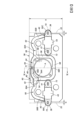
實施形態2之滾珠螺桿致動器10是將左右的線性滾珠軸承70分別做成上下2層的結構。各個滾珠返回構件36在上下2層具有返回通路40。左側第2通路50的傾斜延伸部50B以及右側第2通路52的傾斜延伸部52B分別包含由已形成在對應之通路界定構件43的凹溝43A所形成之部分且呈左右對稱地形成,並到達上下2層的返回通路40之間,且藉由朝向外側開口且上下對稱的連通端50C、52C而連通於上下的各個返回通路40。The
通路界定構件43是朝上下橫跨上下2層的返回通路40而延伸,且一併界定出包含外側端部40A以及內側端部40B之上下2層的返回通路40。The
左側第2通路50的傾斜延伸部50B以及右側第2通路52的傾斜延伸部52B的連通端50C、52C,是分別從通路界定構件43位於上下2層的返回通路40的中間之部位相對於上下2層的返回通路40來向外開口。The connecting ends 50C and 52C of the
在實施形態2中,已注入潤滑油注入通路42之潤滑油也是在第1通路48中流動而到達貫通孔38的左右對稱線A上的分歧位置B,且從分歧位置B在左右對稱的左側第2通路50及右側第2通路52流動,並從相對於上下2層的返回通路40為上下對稱的連通端50C、52C供給至左右的上下2層的線性滾珠軸承70的各個返回通路40。In the second embodiment, the lubricating oil injected into the lubricating
藉此,即使潤滑油注入通路42相對於分歧位置B偏向左右方向的單側,仍然可將潤滑油對左右的上下2層的線性滾珠軸承70之供給以上下均等以及左右均等的方式來進行。Thus, even if the lubricating
由於左側第2通路50的傾斜延伸部50B以及右側第2通路52的傾斜延伸部52B的一部分,詳細而言是傾斜延伸部50B以及傾斜延伸部52B分別在上側的返回通路40中朝上下橫切之部分,是藉由已形成在通路界定構件43之凹溝43A來形成,所以不會有傾斜延伸部50B以及傾斜延伸部52B的構成變得複雜之情形,且該部分的形成會變得較容易。Since the
以上,雖然針對其較理想的實施形態而說明了本發明,但如同只要是所屬技術領域的通常知識者即可以容易地理解一般,本發明並非是受到如此的實施形態所限定之發明,且可在不脫離本發明的主旨之範圍內合宜變更。Although the present invention has been described above with respect to its preferred implementation form, as can be easily understood by a person skilled in the art, the present invention is not limited to such implementation form and can be appropriately modified within the scope of the subject matter of the present invention.
例如,將第1通路48與左側第2通路50的左方延伸部50A在軸線方向的前後互相重疊之部分隔離之分隔壁,亦可不藉由分隔壁構件60來隔離,而是藉由成形加工等而一體成形於滾珠返回構件36。潤滑油供給通路44並不一定要左右對稱地構成。潤滑油對包含潤滑油供給通路44在內之線性滾珠軸承70之供給構造,並不一定要在滑件本體32的軸線方向的兩端的滾珠返回構件36的各個構成,亦可僅於兩端的滾珠返回構件36當中的單側的滾珠返回構件36構成。For example, the partition wall that separates the
線性滾珠軸承70的包含第1通路48、左側第2通路50以及右側第2通路52等的潤滑油供給構造,並不受限於對滾珠螺桿致動器10的滑件30的線性滾珠軸承70之適用,也可以適用在被滾珠螺桿致動器10所驅動以外之滑件30被線性馬達等驅動之線性導引裝置的左右一對的線性滾珠軸承70的潤滑油供給構造上。The lubricating oil supply structure of the
又,在上述實施形態所示之構成要素並非全部均為必要的要素,只要不脫離本發明之主旨,是可合宜取捨選擇的。Furthermore, not all of the constituent elements shown in the above-mentioned embodiments are essential elements, and they can be appropriately selected or discarded without departing from the gist of the present invention.
10:滾珠螺桿致動器
20:導軌
22:側壁
24,41,43A,50D,54A:凹溝
30:滑件
31,31A,38:貫通孔
32:滑件本體
34:螺栓
36:滾珠返回構件
36A:擱架部
39:滾珠脫落防止部
40:返回通路
40A:外側端部
40B:內側端部
42:潤滑油注入通路
43:通路界定構件
44:潤滑油供給通路
46:潤滑油油嘴
48:第1通路
50:左側第2通路
50A:左方延伸部
50B,52B:傾斜延伸部
50C,52C:連通端
52:右側第2通路
52A:右方延伸部
54:左側第3通路
56:右側第3通路
58:第4通路
58A:開口端
60:分隔壁構件
62:凹部
62A:深底底面
62B:淺底底面
64:密封板
68:開口
70:線性滾珠軸承
72,104:滾珠
74:外部通路
76:內部通路
100:滾珠螺桿螺帽部
102:滾珠螺桿軸
A:左右對稱線
B:分歧位置
G:氣隙
H:高度尺寸
VI-VI:線
10: Ball screw actuator
20: Guide rail
22:
圖1是顯示本發明之滾珠螺桿致動器的實施形態1的立體圖。 圖2是實施形態1之滾珠螺桿致動器的主要部位的放大分解立體圖。 圖3是實施形態1之滾珠螺桿致動器的滾珠返回構件的主要部位的立體圖。 圖4是實施形態1之滾珠螺桿致動器的分隔壁構件的主要部位的立體圖。 圖5是實施形態1之滾珠螺桿致動器的滾珠返回構件的正面圖。 圖6是沿著圖5之線VI-VI的剖面圖。 圖7是顯示實施形態1之滾珠螺桿致動器的線性滾珠軸承以及潤滑油通路的概要的概略圖。 圖8是顯示本發明之滾珠螺桿致動器的實施形態2的立體圖。 圖9是實施形態2之滾珠螺桿致動器的滾珠返回構件的立體圖。 圖10是實施形態2之滾珠螺桿致動器的滾珠返回構件的正面圖。 FIG. 1 is a perspective view showing an embodiment 1 of the ball screw actuator of the present invention. FIG. 2 is an enlarged exploded perspective view of the main parts of the ball screw actuator of embodiment 1. FIG. 3 is a perspective view of the main parts of the ball return member of the ball screw actuator of embodiment 1. FIG. 4 is a perspective view of the main parts of the partition wall member of the ball screw actuator of embodiment 1. FIG. 5 is a front view of the ball return member of the ball screw actuator of embodiment 1. FIG. 6 is a cross-sectional view along line VI-VI of FIG. 5. FIG. 7 is a schematic view showing the outline of the linear ball bearing and lubricating oil passage of the ball screw actuator of embodiment 1. FIG8 is a perspective view showing the embodiment 2 of the ball screw actuator of the present invention. FIG9 is a perspective view of the ball return component of the ball screw actuator of the embodiment 2. FIG10 is a front view of the ball return component of the ball screw actuator of the embodiment 2.
38:貫通孔
40:返回通路
40A:外側端部
40B:內側端部
42:潤滑油注入通路
44:潤滑油供給通路
46:潤滑油油嘴
48:第1通路
50:左側第2通路
50C,52C:連通端
52:右側第2通路
54:左側第3通路
56:右側第3通路
58:第4通路
58A:開口端
70:線性滾珠軸承
72:滾珠
74:外部通路
76:內部通路
102:滾珠螺桿軸
A:左右對稱線
B:分歧位置
38: Through hole
40:
Claims (10)
Applications Claiming Priority (2)
| Application Number | Priority Date | Filing Date | Title |
|---|---|---|---|
| WOPCT/JP2023/001727 | 2023-01-20 | ||
| PCT/JP2023/001727 WO2024154340A1 (en) | 2023-01-20 | 2023-01-20 | Ball screw actuator |
Publications (2)
| Publication Number | Publication Date |
|---|---|
| TW202430793A TW202430793A (en) | 2024-08-01 |
| TWI853627B true TWI853627B (en) | 2024-08-21 |
Family
ID=91955734
Family Applications (1)
| Application Number | Title | Priority Date | Filing Date |
|---|---|---|---|
| TW112124281A TWI853627B (en) | 2023-01-20 | 2023-06-29 | Ball Screw Actuator |
Country Status (4)
| Country | Link |
|---|---|
| JP (1) | JPWO2024154340A1 (en) |
| CN (1) | CN120476268A (en) |
| TW (1) | TWI853627B (en) |
| WO (1) | WO2024154340A1 (en) |
Citations (3)
| Publication number | Priority date | Publication date | Assignee | Title |
|---|---|---|---|---|
| TW201719057A (en) * | 2015-10-07 | 2017-06-01 | Thk Co Ltd | Actuator |
| US20210095718A1 (en) * | 2019-10-01 | 2021-04-01 | Toyo Automation Co., Ltd. | Lubricating tube and slide rail device having same |
| US20210277941A1 (en) * | 2020-03-06 | 2021-09-09 | Festo Se & Co. Kg | Linear guide device |
Family Cites Families (4)
| Publication number | Priority date | Publication date | Assignee | Title |
|---|---|---|---|---|
| JPH08114224A (en) * | 1994-10-14 | 1996-05-07 | Nippon Seiko Kk | Oiling structure of linear motion guide bearing device |
| JP2001248637A (en) * | 2000-03-06 | 2001-09-14 | Thk Co Ltd | Linear guide device provided with lubricating function of rolling element |
| EP1845272B1 (en) * | 2006-04-11 | 2012-11-14 | SBC Linear Co.,Ltd. | End-plate for linear motion slider and linear motion slider in use with the end-plate |
| JP5120271B2 (en) * | 2009-01-20 | 2013-01-16 | 日本精工株式会社 | Ball screw |
-
2023
- 2023-01-20 CN CN202380090860.6A patent/CN120476268A/en active Pending
- 2023-01-20 JP JP2024571578A patent/JPWO2024154340A1/ja active Pending
- 2023-01-20 WO PCT/JP2023/001727 patent/WO2024154340A1/en not_active Ceased
- 2023-06-29 TW TW112124281A patent/TWI853627B/en active
Patent Citations (3)
| Publication number | Priority date | Publication date | Assignee | Title |
|---|---|---|---|---|
| TW201719057A (en) * | 2015-10-07 | 2017-06-01 | Thk Co Ltd | Actuator |
| US20210095718A1 (en) * | 2019-10-01 | 2021-04-01 | Toyo Automation Co., Ltd. | Lubricating tube and slide rail device having same |
| US20210277941A1 (en) * | 2020-03-06 | 2021-09-09 | Festo Se & Co. Kg | Linear guide device |
Also Published As
| Publication number | Publication date |
|---|---|
| WO2024154340A1 (en) | 2024-07-25 |
| TW202430793A (en) | 2024-08-01 |
| CN120476268A (en) | 2025-08-12 |
| JPWO2024154340A1 (en) | 2024-07-25 |
Similar Documents
| Publication | Publication Date | Title |
|---|---|---|
| US6682218B2 (en) | Linear motion guide unit with separator between any two adjoining rolling elements | |
| TWI853627B (en) | Ball Screw Actuator | |
| JP4304087B2 (en) | Linear guideway lubrication system | |
| TWI853626B (en) | Ball Screw Actuator | |
| TW201903297A (en) | Film restrictor and hydrostatic bearing module | |
| JP4943204B2 (en) | Guide device, lubricant introduction member and lubricant supply structure | |
| US7488110B2 (en) | End-plate for linear motion slider and linear motion slider in use with the end-plate | |
| JP6316093B2 (en) | Rolling guide device | |
| JP7663082B2 (en) | Linear guide | |
| JP2007528469A (en) | Slider and ball bearing for linear sliding in which this slider is adopted | |
| TWI859455B (en) | Motion guidance device | |
| KR100908168B1 (en) | Bearing Lubricant Supply Device of Transmission for Hybrid Vehicle | |
| JP4106904B2 (en) | Slider for linear motion guide bearing device and linear motion guide bearing device | |
| TWI695125B (en) | Hydrostatic linear slide | |
| JP2012247032A (en) | Uniaxial actuator | |
| TW202300794A (en) | Linear Motion Guidance Unit | |
| JP7600816B2 (en) | Linear guide device | |
| JP2011099466A (en) | Lubricant supply body of linear guide device and linear guide device | |
| JP2009047196A (en) | Linear motion guide bearing device | |
| WO2009084652A1 (en) | Movement guide device | |
| JP2023144576A (en) | Linear guide | |
| JP2009250300A (en) | Linear guide device | |
| JP2024080489A (en) | Slider and linear guide device | |
| JPH0446093Y2 (en) | ||
| JPWO2024154340A5 (en) |