TWI855502B - Image capturing system lens assembly, imaging apparatus and electronic device - Google Patents
Image capturing system lens assembly, imaging apparatus and electronic device Download PDFInfo
- Publication number
- TWI855502B TWI855502B TW112101487A TW112101487A TWI855502B TW I855502 B TWI855502 B TW I855502B TW 112101487 A TW112101487 A TW 112101487A TW 112101487 A TW112101487 A TW 112101487A TW I855502 B TWI855502 B TW I855502B
- Authority
- TW
- Taiwan
- Prior art keywords
- lens
- optical axis
- image
- capture system
- image capture
- Prior art date
Links
Images







Classifications
-
- G—PHYSICS
- G02—OPTICS
- G02B—OPTICAL ELEMENTS, SYSTEMS OR APPARATUS
- G02B13/00—Optical objectives specially designed for the purposes specified below
- G02B13/001—Miniaturised objectives for electronic devices, e.g. portable telephones, webcams, PDAs, small digital cameras
- G02B13/0015—Miniaturised objectives for electronic devices, e.g. portable telephones, webcams, PDAs, small digital cameras characterised by the lens design
-
- G—PHYSICS
- G02—OPTICS
- G02B—OPTICAL ELEMENTS, SYSTEMS OR APPARATUS
- G02B9/00—Optical objectives characterised both by the number of the components and their arrangements according to their sign, i.e. + or -
- G02B9/64—Optical objectives characterised both by the number of the components and their arrangements according to their sign, i.e. + or - having more than six components
-
- G—PHYSICS
- G02—OPTICS
- G02B—OPTICAL ELEMENTS, SYSTEMS OR APPARATUS
- G02B13/00—Optical objectives specially designed for the purposes specified below
- G02B13/001—Miniaturised objectives for electronic devices, e.g. portable telephones, webcams, PDAs, small digital cameras
- G02B13/0015—Miniaturised objectives for electronic devices, e.g. portable telephones, webcams, PDAs, small digital cameras characterised by the lens design
- G02B13/002—Miniaturised objectives for electronic devices, e.g. portable telephones, webcams, PDAs, small digital cameras characterised by the lens design having at least one aspherical surface
- G02B13/0045—Miniaturised objectives for electronic devices, e.g. portable telephones, webcams, PDAs, small digital cameras characterised by the lens design having at least one aspherical surface having five or more lenses
-
- G—PHYSICS
- G02—OPTICS
- G02B—OPTICAL ELEMENTS, SYSTEMS OR APPARATUS
- G02B13/00—Optical objectives specially designed for the purposes specified below
- G02B13/001—Miniaturised objectives for electronic devices, e.g. portable telephones, webcams, PDAs, small digital cameras
- G02B13/0055—Miniaturised objectives for electronic devices, e.g. portable telephones, webcams, PDAs, small digital cameras employing a special optical element
- G02B13/0065—Miniaturised objectives for electronic devices, e.g. portable telephones, webcams, PDAs, small digital cameras employing a special optical element having a beam-folding prism or mirror
-
- G—PHYSICS
- G02—OPTICS
- G02B—OPTICAL ELEMENTS, SYSTEMS OR APPARATUS
- G02B13/00—Optical objectives specially designed for the purposes specified below
- G02B13/02—Telephoto objectives, i.e. systems of the type + - in which the distance from the front vertex to the image plane is less than the equivalent focal length
-
- G—PHYSICS
- G02—OPTICS
- G02B—OPTICAL ELEMENTS, SYSTEMS OR APPARATUS
- G02B13/00—Optical objectives specially designed for the purposes specified below
- G02B13/06—Panoramic objectives; So-called "sky lenses" including panoramic objectives having reflecting surfaces
Landscapes
- Physics & Mathematics (AREA)
- General Physics & Mathematics (AREA)
- Optics & Photonics (AREA)
- Lenses (AREA)
Abstract
Description
本揭示係關於一種影像擷取系統鏡片組和取像裝置,特別是關於一種可應用於電子裝置的影像擷取系統鏡片組和取像裝置。The present disclosure relates to an image capture system lens assembly and an image capture device, and more particularly to an image capture system lens assembly and an image capture device that can be applied to electronic devices.
隨著半導體製程技術更加精進,使得電子感光元件性能有所提升,畫素可達到更微小的尺寸,因此,具備高成像品質的光學鏡頭儼然成為不可或缺的一環。而隨著科技日新月異,配備光學鏡頭的電子裝置的應用範圍更加廣泛,對於光學鏡頭的要求也是更加多樣化,由於往昔之光學鏡頭較不易在成像品質、敏感度、光圈大小、體積或視角等需求間取得平衡,本發明提供一影像擷取系統鏡片組,藉由其適當的透鏡配置,可達到兼具廣視角、微型化、大光圈及高成像品質的特性,以應用於更廣泛的產品中。As semiconductor manufacturing technology becomes more sophisticated, the performance of electronic photosensitive components has been improved, and pixels can reach a smaller size. Therefore, optical lenses with high imaging quality have become an indispensable part. With the rapid development of technology, the application range of electronic devices equipped with optical lenses has become wider, and the requirements for optical lenses have become more diverse. Since it is difficult for optical lenses in the past to strike a balance between the requirements of imaging quality, sensitivity, aperture size, volume or viewing angle, the present invention provides an image capture system lens set, which can achieve the characteristics of wide viewing angle, miniaturization, large aperture and high imaging quality through its appropriate lens configuration, so as to be applied to a wider range of products.
本揭示提供一種影像擷取系統鏡片組,包含七片透鏡,該七片透鏡由物側至像側依序為第一透鏡、第二透鏡、第三透鏡、第四透鏡、第五透鏡、第六透鏡及第七透鏡,該第一透鏡至該第七透鏡中各透鏡皆包含朝向物側的物側面與朝向像側的像側面; 其中,較佳地,該第五透鏡具負屈折力;該影像擷取系統鏡片組的焦距為f,該第七透鏡的焦距為f7,該第一透鏡物側面與一成像面之間於光軸上的距離為TL,該第三透鏡與該第四透鏡之間的光軸距離為T34,該第一透鏡物側面與該第七透鏡像側面之間於光軸上的距離為TD,該第五透鏡物側面曲率半徑為R9,其滿足下列關係式: 7.50 < TL/f < 23.00; -2.50 < f/f7 < 0.16; 0.18 < T34/TD < 0.60;及 -0.03 < f/R9 < 1.50。 The present disclosure provides an image capture system lens set, comprising seven lenses, the seven lenses are sequentially a first lens, a second lens, a third lens, a fourth lens, a fifth lens, a sixth lens and a seventh lens from the object side to the image side, each lens from the first lens to the seventh lens comprises an object side surface facing the object side and an image side surface facing the image side; Preferably, the fifth lens has negative refractive power; the focal length of the image capture system lens group is f, the focal length of the seventh lens is f7, the distance between the object side of the first lens and an imaging plane on the optical axis is TL, the distance between the third lens and the fourth lens on the optical axis is T34, the distance between the object side of the first lens and the image side of the seventh lens on the optical axis is TD, and the radius of curvature of the object side of the fifth lens is R9, which satisfies the following relationship: 7.50 < TL/f < 23.00; -2.50 < f/f7 < 0.16; 0.18 < T34/TD < 0.60; and -0.03 < f/R9 < 1.50.
本揭示提供一種取像裝置,包含前述影像擷取系統鏡片組、一反射元件與一電子感光元件。The present disclosure provides an imaging device, comprising the aforementioned image capturing system lens set, a reflective element and an electronic photosensitive element.
本揭示提供一種電子裝置,包含有前述取像裝置。The present disclosure provides an electronic device including the aforementioned imaging device.
本揭示提供一種影像擷取系統鏡片組,包含七片透鏡,該七片透鏡由物側至像側依序為第一透鏡、第二透鏡、第三透鏡、第四透鏡、第五透鏡、第六透鏡及第七透鏡,該第一透鏡至該第七透鏡中各透鏡皆包含朝向物側的物側面與朝向像側的像側面; 其中,較佳地,該第七透鏡具負屈折力;較佳地,該第五透鏡像側面於近光軸處為凹面;該第一透鏡物側面與一成像面之間於光軸上的距離為TL,該影像擷取系統鏡片組的焦距為f,該影像擷取系統鏡片組中最大視角的一半為HFOV,該第一透鏡至該第七透鏡之間的所有兩相鄰透鏡於光軸上之間隔距離中數值最大者為ATmax1,該第一透鏡、該第二透鏡與該第三透鏡的合成焦距為f123,該第四透鏡、該第五透鏡、該第六透鏡與該第七透鏡的合成焦距為f4567,其滿足下列關係式: 8.80 < TL/f < 23.00; 80.0 度 < HFOV < 140.0 度; 2.30 < ATmax1/f < 15.00;及 -10.00 < f123/f4567 < 0.20。 The present disclosure provides an image capture system lens set, comprising seven lenses, the seven lenses are sequentially a first lens, a second lens, a third lens, a fourth lens, a fifth lens, a sixth lens and a seventh lens from the object side to the image side, each lens from the first lens to the seventh lens comprises an object side surface facing the object side and an image side surface facing the image side; Preferably, the seventh lens has negative refractive power; preferably, the image side of the fifth lens is concave near the optical axis; the distance between the object side of the first lens and an imaging plane on the optical axis is TL, the focal length of the image capture system lens set is f, half of the maximum viewing angle in the image capture system lens set is HFOV, and the first lens to The largest value of the interval distance between all two adjacent lenses on the optical axis between the seventh lens is ATmax1, the composite focal length of the first lens, the second lens and the third lens is f123, and the composite focal length of the fourth lens, the fifth lens, the sixth lens and the seventh lens is f4567, which satisfies the following relationship: 8.80 < TL/f < 23.00; 80.0 degrees < HFOV < 140.0 degrees; 2.30 < ATmax1/f < 15.00; and -10.00 < f123/f4567 < 0.20.
本揭示提供一種影像擷取系統鏡片組,包含七片透鏡,該七片透鏡由物側至像側依序為第一透鏡、第二透鏡、第三透鏡、第四透鏡、第五透鏡、第六透鏡及第七透鏡,該第一透鏡至該第七透鏡中各透鏡皆包含朝向物側的物側面與朝向像側的像側面; 其中,較佳地,該第二透鏡具負屈折力;該第三透鏡與該第四透鏡之間的光軸距離為最大鏡間距,該第三透鏡與該第四透鏡之間有一反射元件,該影像擷取系統鏡片組的焦距為f,該第七透鏡的焦距為f7,該第一透鏡物側面與一成像面之間於光軸上的距離為TL,該第四透鏡物側面的最大有效半徑為Y4R1,該第七透鏡像側面的最大有效半徑為Y7R2,該影像擷取系統鏡片組的光圈值為Fno,其滿足下列關係式: 6.00 < TL/f < 28.00; -3.00 < f/f7 < 0.22; 1.30 < Y7R2/Y4R1 < 4.50;及 1.00 < Fno < 2.60。 The present disclosure provides an image capture system lens set, comprising seven lenses, the seven lenses are sequentially a first lens, a second lens, a third lens, a fourth lens, a fifth lens, a sixth lens and a seventh lens from the object side to the image side, each lens from the first lens to the seventh lens comprises an object side surface facing the object side and an image side surface facing the image side; Preferably, the second lens has negative refractive power; the optical axis distance between the third lens and the fourth lens is the maximum lens distance, there is a reflective element between the third lens and the fourth lens, the focal length of the image capture system lens group is f, the focal length of the seventh lens is f7, the distance between the object side of the first lens and an imaging surface on the optical axis is TL, the maximum effective radius of the object side of the fourth lens is Y4R1, the maximum effective radius of the image side of the seventh lens is Y7R2, and the aperture value of the image capture system lens group is Fno, which satisfies the following relationship: 6.00 < TL/f < 28.00; -3.00 < f/f7 < 0.22; 1.30 < Y7R2/Y4R1 < 4.50; and 1.00 < Fno < 2.60.
當TL/f 滿足條件時,有助於在總長與視角間取得平衡,並使系統具有廣視角的特性。When TL/f meets the requirements, it helps to achieve a balance between total length and viewing angle and makes the system have the characteristics of a wide viewing angle.
當f/f7滿足條件時,可調整第七透鏡之屈折力,有助於平衡影像擷取系統鏡片組像側端的屈折力配置,有助於修正球差等像差。When f/f7 meets the conditions, the refractive power of the seventh lens can be adjusted, which helps to balance the refractive power configuration of the image capture system lens group on the image side, and helps to correct aberrations such as spherical aberration.
當T34/TD滿足條件時,可調整第三透鏡與第四透鏡間距在系統中的比例,使其有足夠大的空間,以達成更靈活的空間配置。When T34/TD meets the requirements, the ratio of the distance between the third lens and the fourth lens in the system can be adjusted to allow for a large enough space to achieve a more flexible spatial configuration.
當f/R9滿足條件時,可調整第五透鏡物側面之面型,可調整光線的行進方向,有助於減少中心光路鄰近視場之彗差。When f/R9 is met, the shape of the object side of the fifth lens can be adjusted to adjust the direction of light travel, which helps to reduce coma in the field of view near the central optical path.
當HFOV滿足條件時,可增加影像拍攝範圍,接收更多周遭環境之空間資訊,使應用於各種領域。When HFOV meets the conditions, the image capture range can be increased, more spatial information of the surrounding environment can be received, and it can be applied in various fields.
當ATmax1/f 滿足條件時,可調整最大鏡間距與焦距之比例,有助於提供透鏡之中有足夠的空間,以達成更多樣的配置。When ATmax1/f meets the requirements, the ratio of the maximum lens spacing to the focal length can be adjusted, which helps to provide enough space in the lens to achieve a variety of configurations.
當f123/f4567滿足條件時,有助於使系統前後端透鏡相互配合以修正像差。When f123/f4567 meets the conditions, it helps to make the front and rear lenses of the system cooperate with each other to correct aberrations.
當Y7R2/Y4R1滿足條件時,可調整系統後段透鏡有效徑比例,有助於增大成像面。When Y7R2/Y4R1 meets the conditions, the effective diameter ratio of the system's rear lens can be adjusted to help increase the imaging surface.
當Fno滿足條件時,可調整光圈大小,有助於增加系統之進光量以擴增應用範圍。When Fno meets the requirements, the aperture size can be adjusted to increase the amount of light entering the system and expand the application range.
本揭示提供一種影像擷取系統鏡片組 ,包含七片透鏡,該七片透鏡由物側至像側依序為第一透鏡、第二透鏡、第三透鏡、第四透鏡、第五透鏡、第六透鏡及第七透鏡,該第一透鏡至該第七透鏡中各透鏡皆包含朝向物側的物側面與朝向像側的像側面。The present disclosure provides an image capture system lens assembly, comprising seven lenses, wherein the seven lenses are a first lens, a second lens, a third lens, a fourth lens, a fifth lens, a sixth lens and a seventh lens in order from the object side to the image side, and each lens from the first lens to the seventh lens comprises an object side surface facing the object side and an image side surface facing the image side.
第二透鏡具負屈折力,可與第一透鏡相互配合,有助於增大視角。The second lens has negative refractive power and can cooperate with the first lens to help increase the viewing angle.
第二透鏡像側面於近光軸處為凹面,可調整第二透鏡的面型,有助於修正像散之像差。The image side surface of the second lens is concave near the optical axis, and the surface shape of the second lens can be adjusted to help correct the aberration of astigmatism.
第三透鏡具正屈折力,可平衡影像擷取系統鏡片組物側端的屈折力分布,有助於降低敏感度。The third lens has positive refractive power, which can balance the refractive power distribution on the object side of the image acquisition system lens assembly, helping to reduce sensitivity.
第四透鏡物側面於近光軸處為凸面,可調整第四透鏡之面形,有助於增大光圈。The object side of the fourth lens is convex near the optical axis, and the shape of the fourth lens can be adjusted to help increase the aperture.
第五透鏡具負屈折力,可與第四透鏡相互配合以修正球差等像差。The fifth lens has negative refractive power and can cooperate with the fourth lens to correct aberrations such as spherical aberration.
第五透鏡物側面於近光軸處為凸面,可調整第五透鏡物側面之面型,可調整光線的行進方向,有助於減少中心光路鄰近視場之彗差。The object side of the fifth lens is convex near the optical axis. The shape of the object side of the fifth lens can be adjusted to adjust the direction of light travel, which helps to reduce the coma aberration near the central optical path of the field of view.
第五透鏡像側面於近光軸處為凹面,可有效平衡系統物側端透鏡所產生之像差,以提升影像品質。The image side surface of the fifth lens is concave near the optical axis, which can effectively balance the aberration produced by the object side lens of the system to improve image quality.
第七透鏡具負屈折力,可調整第七透鏡之屈折力,有助於平衡影像擷取系統鏡片組像側端的屈折力配置,有助於修正球差等像差。The seventh lens has negative refractive power. The refractive power of the seventh lens can be adjusted, which helps to balance the refractive power configuration of the image capture system lens group on the image side, and helps to correct aberrations such as spherical aberration.
第七透鏡像側面為非球面且於其離軸處具有凸面,可提升第七透鏡的設計自由度,可有效平衡近軸與離軸的聚焦位置,以修正像彎曲。The image side surface of the seventh lens is aspherical and has a convex surface at its off-axis position, which can improve the design freedom of the seventh lens and effectively balance the near-axis and off-axis focusing positions to correct image curvature.
第七透鏡的材質為塑膠,且第七透鏡的物側面及像側面皆為非球面,可有效降低生產成本,提升設計自由度,有助於改善影像品質與增加量產能力。The seventh lens is made of plastic, and both the object side and image side surfaces of the seventh lens are aspherical, which can effectively reduce production costs, increase design freedom, and help improve image quality and increase mass production capabilities.
第一透鏡至第七透鏡之間所有兩相鄰透鏡皆具有空氣間隔,可確保鏡頭組裝的簡易性,以增加組裝良率。All two adjacent lenses between the first lens to the seventh lens have air spacers, which can ensure the simplicity of lens assembly and increase assembly yield.
影像擷取系統鏡片組的焦距為f,第一透鏡物側面與成像面之間於光軸上的距離為TL,當影像擷取系統鏡片組滿足下列關係式:6.00 < TL/f < 28.00,有助於在總長與視角間取得平衡,並使系統具有廣視角的特性。其中,亦可滿足:7.50 < TL/f < 23.00。其中,亦可滿足:8.80 < TL/f < 23.00。其中,亦可滿足:8.80 < TL/f < 22.00。The focal length of the image capture system lens group is f, and the distance between the object side of the first lens and the image plane on the optical axis is TL. When the image capture system lens group satisfies the following relationship: 6.00 < TL/f < 28.00, it helps to achieve a balance between the total length and the viewing angle, and makes the system have the characteristics of a wide viewing angle. Among them, it can also satisfy: 7.50 < TL/f < 23.00. Among them, it can also satisfy: 8.80 < TL/f < 23.00. Among them, it can also satisfy: 8.80 < TL/f < 22.00.
影像擷取系統鏡片組的焦距為f,第七透鏡的焦距為f7,當影像擷取系統鏡片組滿足下列關係式:-3.00 < f/f7 < 0.22,可調整第七透鏡之屈折力,有助於平衡影像擷取系統鏡片組像側端的屈折力配置,有助於修正球差等像差。其中,亦可滿足: -2.50 < f/f7 < 0.16。其中,亦可滿足:-1.50 < f/f7 < 0.10。其中,亦可滿足: -0.90 < f/f7 < 0.00。其中,亦可滿足: -0.50 < f/f7 < -0.03。The focal length of the image capture system lens group is f, and the focal length of the seventh lens is f7. When the image capture system lens group satisfies the following relationship: -3.00 < f/f7 < 0.22, the refractive power of the seventh lens can be adjusted, which helps to balance the refractive power configuration of the image capture system lens group on the image side, and helps to correct aberrations such as spherical aberration. Among them, it can also be satisfied: -2.50 < f/f7 < 0.16. Among them, it can also be satisfied: -1.50 < f/f7 < 0.10. Among them, it can also be satisfied: -0.90 < f/f7 < 0.00. Among them, it can also be satisfied: -0.50 < f/f7 < -0.03.
第三透鏡與第四透鏡之間的光軸距離為T34,第一透鏡物側面與第七透鏡像側面之間於光軸上的距離為TD,當影像擷取系統鏡片組滿足下列關係式:0.18 < T34/TD < 0.60,可調整第三透鏡與第四透鏡間距在系統中的比例,使其有足夠大的空間,以達成更靈活的空間配置。其中,亦可滿足:0.20 < T34/TD < 0.50。其中,亦可滿足:0.27 < T34/TD < 0.45。The optical axis distance between the third lens and the fourth lens is T34, and the distance between the object side of the first lens and the image side of the seventh lens on the optical axis is TD. When the image capture system lens group satisfies the following relationship: 0.18 < T34/TD < 0.60, the ratio of the distance between the third lens and the fourth lens in the system can be adjusted to have a large enough space to achieve a more flexible spatial configuration. Among them, it can also meet: 0.20 < T34/TD < 0.50. Among them, it can also meet: 0.27 < T34/TD < 0.45.
影像擷取系統鏡片組的焦距為f,第五透鏡物側面曲率半徑為R9,當影像擷取系統鏡片組滿足下列關係式:-0.03 < f/R9 < 1.50,可調整第五透鏡物側面之面型,可調整光線的行進方向,有助於減少中心光路鄰近視場之彗差。其中,亦可滿足:0.05 < f/R9 < 1.00。其中,亦可滿足:0.10 < f/R9 < 0.60。The focal length of the image capture system lens group is f, and the radius of curvature of the fifth lens side surface is R9. When the image capture system lens group satisfies the following relationship: -0.03 < f/R9 < 1.50, the surface shape of the fifth lens side surface can be adjusted, and the direction of light travel can be adjusted, which helps to reduce the coma of the field of view near the central optical path. Among them, it can also meet: 0.05 < f/R9 < 1.00. Among them, it can also meet: 0.10 < f/R9 < 0.60.
影像擷取系統鏡片組的光圈值為Fno,當影像擷取系統鏡片組滿足下列關係式:1.00 < Fno < 2.60,可調整光圈大小,有助於增加系統之進光量以擴增應用範圍。其中,亦可滿足: 1.00 < Fno < 2.20。其中,亦可滿足:1.30 < Fno < 2.20。其中,亦可滿足:1.50 < Fno < 2.00。The aperture value of the image capture system lens group is Fno. When the image capture system lens group satisfies the following relationship: 1.00 < Fno < 2.60, the aperture size can be adjusted to help increase the amount of light entering the system to expand the application range. Among them, it can also meet: 1.00 < Fno < 2.20. Among them, it can also meet: 1.30 < Fno < 2.20. Among them, it can also meet: 1.50 < Fno < 2.00.
影像擷取系統鏡片組中最大視角的一半為HFOV,當影像擷取系統鏡片組滿足下列關係式:55.0 度 < HFOV < 140.0 度,可增加影像拍攝範圍,接收更多周遭環境之空間資訊,使應用於各種領域。其中,亦可滿足: 65.0 度 < HFOV < 140.0 度。其中,亦可滿足:65.0 度 < HFOV < 130.0 度。其中,亦可滿足:80.0 度 < HFOV < 140.0 度。其中,亦可滿足:80.0 度 < HFOV < 125.0度。其中,亦可滿足:90.0 度 < HFOV < 120.0度。Half of the maximum viewing angle of the image acquisition system lens group is HFOV. When the image acquisition system lens group satisfies the following relationship: 55.0 degrees < HFOV < 140.0 degrees, the image shooting range can be increased, more spatial information of the surrounding environment can be received, and it can be applied to various fields. Among them, it can also meet: 65.0 degrees < HFOV < 140.0 degrees. Among them, it can also meet: 65.0 degrees < HFOV < 130.0 degrees. Among them, it can also meet: 80.0 degrees < HFOV < 140.0 degrees. Among them, it can also meet: 80.0 degrees < HFOV < 125.0 degrees. Among them, it can also meet the following conditions: 90.0 degrees < HFOV < 120.0 degrees.
第一透鏡至第七透鏡之間的所有兩相鄰透鏡於光軸上之間隔距離中數值最大者為ATmax1,所述所有兩相鄰透鏡於光軸上之間隔距離中數值第二大者為 ATmax2,當影像擷取系統鏡片組滿足下列關係式:1.25 < ATmax1/ATmax2,可調整最大鏡間距有足夠的空間容納反射元件,有助於達成光路轉折,以縮減系統厚度。The largest value of the distance between all two adjacent lenses on the optical axis between the first lens to the seventh lens is ATmax1, and the second largest value of the distance between all two adjacent lenses on the optical axis is ATmax2. When the lens assembly of the image capture system satisfies the following relationship: 1.25 < ATmax1/ATmax2, the maximum lens distance can be adjusted to have enough space to accommodate the reflective element, which helps to achieve optical path bending and reduce the system thickness.
第一透鏡物側面的最大有效半徑為Y1R1,第五透鏡像側面的最大有效半徑為Y5R2,當影像擷取系統鏡片組滿足下列關係式:2.80 < Y1R1/Y5R2 < 20.00,可調整系統物側端與中段之有效徑比例,有助於增大視角以配合超廣角之應用。其中, 亦可滿足:4.00 < Y1R1/Y5R2 < 15.00。The maximum effective radius of the first lens on the object side is Y1R1, and the maximum effective radius of the fifth lens on the image side is Y5R2. When the image capture system lens group satisfies the following relationship: 2.80 < Y1R1/Y5R2 < 20.00, the effective diameter ratio of the object side end and the middle section of the system can be adjusted, which helps to increase the viewing angle to match the application of ultra-wide angle. Among them, it can also meet: 4.00 < Y1R1/Y5R2 < 15.00.
第六透鏡阿貝數為V6,第七透鏡阿貝數為V7,當影像擷取系統鏡片組滿足下列關係式:1.25 < V6/V7 < 4.00,可調整第六透鏡與第七透鏡的材質配置,有助於在色差與像散之間取得平衡。其中,亦可滿足:1.60 < V6/V7 < 3.00。The Abbe number of the sixth lens is V6, and the Abbe number of the seventh lens is V7. When the image capture system lens group satisfies the following relationship: 1.25 < V6/V7 < 4.00, the material configuration of the sixth lens and the seventh lens can be adjusted to help achieve a balance between chromatic aberration and astigmatism. Among them, it can also meet: 1.60 < V6/V7 < 3.00.
第五透鏡與第六透鏡之間的光軸距離為T56,第六透鏡與第七透鏡之間的光軸距離為T67,當影像擷取系統鏡片組滿足下列關係式:1.30 < T67/T56 < 30.00,可調整系統像側端透鏡的位置分布,有助於在體積尺寸與成像品質間取得平衡。其中,亦可滿足:1.40 < T67/T56 < 25.00。其中,亦可滿足:2.00 < T67/T56 < 10.00。The optical axis distance between the fifth lens and the sixth lens is T56, and the optical axis distance between the sixth lens and the seventh lens is T67. When the image capture system lens group satisfies the following relationship: 1.30 < T67/T56 < 30.00, the position distribution of the image side lens of the system can be adjusted to help achieve a balance between volume size and imaging quality. Among them, it can also meet: 1.40 < T67/T56 < 25.00. Among them, it can also meet: 2.00 < T67/T56 < 10.00.
影像擷取系統鏡片組的最大像高為 ImgH,當影像擷取系統鏡片組滿足下列關係式:2.70[mm] < ImgH < 7.00[mm],可使系統有適當的成像面大小,以滿足產品應用需求。其中,亦可滿足:3.00[mm] < ImgH < 5.50[mm]。The maximum image height of the image acquisition system lens group is ImgH. When the image acquisition system lens group satisfies the following relationship: 2.70[mm] < ImgH < 7.00[mm], the system can have an appropriate imaging surface size to meet the product application requirements. Among them, it can also meet: 3.00[mm] < ImgH < 5.50[mm].
第七透鏡物側面與光軸交點至第七透鏡物側面光學有效區邊界與光軸平行之位移量為SAG71,第七透鏡於光軸上的厚度為CT7,當影像擷取系統鏡片組滿足下列關係式:-6.00 < SAG71/CT7 < 0.01,可調整第七透鏡物側面之離軸面型與第七透鏡中心厚度的比值,有助於控制透鏡周邊形狀以修正離軸像差。其中,亦可滿足:-4.00 < SAG71/CT7 < -0.50。The displacement from the intersection of the seventh lens object side and the optical axis to the boundary of the seventh lens object side optical effective area parallel to the optical axis is SAG71, and the thickness of the seventh lens on the optical axis is CT7. When the image acquisition system lens group satisfies the following relationship: -6.00 < SAG71/CT7 < 0.01, the ratio of the off-axis surface shape of the seventh lens object side and the thickness of the seventh lens center can be adjusted, which helps to control the peripheral shape of the lens to correct off-axis aberrations. Among them, it can also meet: -4.00 < SAG71/CT7 < -0.50.
第一透鏡至第七透鏡之間的所有兩相鄰透鏡於光軸上之間隔距離中數值最大者為ATmax1,影像擷取系統鏡片組的焦距為f,當影像擷取系統鏡片組滿足下列關係式:2.30 < ATmax1/f < 15.00,可調整最大鏡間距與焦距之比例,有助於提供透鏡之中有足夠的空間,以達成更多樣的配置。其中,亦可滿足:2.70 < ATmax1/f < 9.00。其中,亦可滿足:2.90 < ATmax1/f < 6.00。The largest value of the distance between all two adjacent lenses on the optical axis between the first lens to the seventh lens is ATmax1, and the focal length of the image acquisition system lens group is f. When the image acquisition system lens group satisfies the following relationship: 2.30 < ATmax1/f < 15.00, the ratio of the maximum lens distance and the focal length can be adjusted, which helps to provide sufficient space in the lens to achieve more diverse configurations. Among them, it can also meet: 2.70 < ATmax1/f < 9.00. Among them, it can also meet: 2.90 < ATmax1/f < 6.00.
第一透鏡、第二透鏡與第三透鏡的合成焦距為f123,第四透鏡、第五透鏡、第六透鏡與第七透鏡的合成焦距為f4567,當影像擷取系統鏡片組滿足下列關係式:-10.00 < f123/f4567 < 0.20,有助於使系統前後端透鏡相互配合以修正像差。其中,亦可滿足:-8.50 < f123/f4567 < 0.00。其中,亦可滿足: -7.00 < f123/f4567 < -0.30。其中,亦可滿足:-6.00 < f123/f4567 < -1.10。The composite focal length of the first lens, the second lens and the third lens is f123, and the composite focal length of the fourth lens, the fifth lens, the sixth lens and the seventh lens is f4567. When the image capture system lens group satisfies the following relationship: -10.00 < f123/f4567 < 0.20, it is helpful to make the front and rear lenses of the system cooperate with each other to correct aberration. Among them, it can also satisfy: -8.50 < f123/f4567 < 0.00. Among them, it can also satisfy: -7.00 < f123/f4567 < -0.30. Among them, it can also satisfy: -6.00 < f123/f4567 < -1.10.
第三透鏡與第四透鏡之間的光軸距離為T34,第三透鏡於光軸上的厚度為CT3,當影像擷取系統鏡片組滿足下列關係式:0.30 < T34/CT3 < 20.00,可調整系統中段的鏡間距與透鏡厚度的比例,有助於使透鏡有適當的厚度以維持製造良率。其中,亦可滿足:0.90 < T34/CT3 < 15.00。其中,亦可滿足:1.50 < T34/CT3 < 11.00。The optical axis distance between the third lens and the fourth lens is T34, and the thickness of the third lens on the optical axis is CT3. When the image capture system lens group satisfies the following relationship: 0.30 < T34/CT3 < 20.00, the ratio of the lens spacing and lens thickness in the middle section of the system can be adjusted, which helps to make the lens have an appropriate thickness to maintain the manufacturing yield. Among them, it can also meet: 0.90 < T34/CT3 < 15.00. Among them, it can also meet: 1.50 < T34/CT3 < 11.00.
第五透鏡物側面曲率半徑為R9,第五透鏡像側面曲率半徑為R10,當影像擷取系統鏡片組滿足下列關係式:0.90 < (R9+R10)/(R9-R10) < 5.00,可調整第五透鏡物側面與像側面之曲率半徑,有助於修正周邊視場的像散等像差。其中,亦可滿足:1.50 < (R9+R10)/(R9-R10) < 3.20。The curvature radius of the fifth lens object side surface is R9, and the curvature radius of the fifth lens image side surface is R10. When the image capture system lens group satisfies the following relationship: 0.90 < (R9+R10)/(R9-R10) < 5.00, the curvature radius of the fifth lens object side surface and image side surface can be adjusted, which helps to correct aberrations such as astigmatism in the peripheral field of view. Among them, it can also satisfy: 1.50 < (R9+R10)/(R9-R10) < 3.20.
第四透鏡的焦距為f4,第六透鏡與第七透鏡之間的光軸距離為T67,當影像擷取系統鏡片組滿足下列關係式:0.20 < f4/T67 < 20.00,可調整系統像側端透鏡焦距與鏡間距之比例,有助於在減少製造公差與減少溫度效應之間取得平衡。其中,亦可滿足:0.80 < f4/T67 < 14.00。其中,亦可滿足:1.20 < f4/T67 < 9.00。The focal length of the fourth lens is f4, and the optical axis distance between the sixth lens and the seventh lens is T67. When the image capture system lens group satisfies the following relationship: 0.20 < f4/T67 < 20.00, the ratio of the focal length of the image-side lens and the lens distance can be adjusted to help achieve a balance between reducing manufacturing tolerance and reducing temperature effects. Among them, it can also meet: 0.80 < f4/T67 < 14.00. Among them, it can also meet: 1.20 < f4/T67 < 9.00.
第一透鏡為玻璃材質,該第一透鏡的折射率為N1,當影像擷取系統鏡片組滿足下列關係式:1.680 < N1 < 2.500, 可調整第一透鏡材質,使第一透鏡具有抗刮的特性,避免鏡片磨損影響成像。其中,亦可滿足:1.730 < N1 < 2.200。The first lens is made of glass, and the refractive index of the first lens is N1. When the lens group of the image capture system satisfies the following relationship: 1.680 < N1 < 2.500, the material of the first lens can be adjusted to make the first lens have a scratch-resistant property to prevent the lens wear from affecting the imaging. Among them, it can also meet: 1.730 < N1 < 2.200.
第四透鏡物側面的最大有效半徑為Y4R1,第七透鏡像側面的最大有效半徑為Y7R2,當影像擷取系統鏡片組滿足下列關係式:1.30 < Y7R2/Y4R1 < 4.50,可調整系統後段透鏡有效徑比例,有助於增大成像面。其中,亦可滿足:1.50 < Y7R2/Y4R1 < 2.80。The maximum effective radius of the fourth lens on the object side is Y4R1, and the maximum effective radius of the seventh lens on the image side is Y7R2. When the image capture system lens group satisfies the following relationship: 1.30 < Y7R2/Y4R1 < 4.50, the effective diameter ratio of the rear lens of the system can be adjusted to help increase the imaging surface. Among them, it can also meet: 1.50 < Y7R2/Y4R1 < 2.80.
第二透鏡像側面曲率半徑為R4,第五透鏡像側面曲率半徑為R10,第六透鏡與第七透鏡之間的光軸距離為T67,當影像擷取系統鏡片組滿足下列關係式:1.00 < (R4+R10)/T67 < 18.00,可調整第二透鏡與第五透鏡之面型與第六、七片鏡間距的比例,有助於強化系統結構強度,以提升系統穩定性。其中,亦可滿足: 1.50 < (R4+R10)/T67 < 7.00。The radius of curvature of the image side of the second lens is R4, the radius of curvature of the image side of the fifth lens is R10, and the optical axis distance between the sixth lens and the seventh lens is T67. When the image capture system lens group satisfies the following relationship: 1.00 < (R4+R10)/T67 < 18.00, the ratio of the surface shape of the second lens and the fifth lens and the distance between the sixth and seventh lenses can be adjusted, which helps to strengthen the system structure strength and improve the system stability. Among them, it can also meet: 1.50 < (R4+R10)/T67 < 7.00.
第二透鏡阿貝數為V2,第七透鏡阿貝數為V7,當影像擷取系統鏡片組滿足下列關係式:1.10 < V2/V7 < 3.50,可調整影像擷取系統鏡片組的材質配置,以修正色差。The Abbe number of the second lens is V2, and the Abbe number of the seventh lens is V7. When the image acquisition system lens group satisfies the following relationship: 1.10 < V2/V7 < 3.50, the material configuration of the image acquisition system lens group can be adjusted to correct chromatic aberration.
第一透鏡物側面的最大有效半徑為Y1R1,第一透鏡像側面的最大有效半徑為Y1R2,第一透鏡於光軸上的厚度為CT1,當影像擷取系統鏡片組滿足下列關係式:2.50 < (Y1R1-Y1R2)/CT1 < 15.00,可調整第一透鏡物側面與像側面有效半徑與厚度的比例,以控制第一透鏡外型,有助於達成超廣角之應用。其中,亦可滿足:3.30 < (Y1R1-Y1R2)/CT1 < 10.00。The maximum effective radius of the object side of the first lens is Y1R1, the maximum effective radius of the image side of the first lens is Y1R2, and the thickness of the first lens on the optical axis is CT1. When the image capture system lens group satisfies the following relationship: 2.50 < (Y1R1-Y1R2)/CT1 < 15.00, the ratio of the effective radius and thickness of the object side and image side of the first lens can be adjusted to control the appearance of the first lens, which is helpful to achieve ultra-wide-angle applications. Among them, it can also meet: 3.30 < (Y1R1-Y1R2)/CT1 < 10.00.
本揭示前述影像擷取系統鏡片組包含一反射元件,位於第一透鏡與第七透鏡之間,可提供系統不同的光路走向,使鏡頭空間配置更為靈活,有助於減少機構上之限制。The image capture system lens assembly disclosed herein includes a reflective element located between the first lens and the seventh lens, which can provide the system with different light paths, making the lens space configuration more flexible and helping to reduce the limitations on the structure.
本揭示前述影像擷取系統鏡片組包含一光圈位於該反射元件與該成像面之間,可調整光圈於影像擷取系統鏡片組之位置,可在增加周邊視場相對照度與增加視角之間取得平衡。The image capture system lens assembly disclosed herein includes an aperture located between the reflective element and the imaging surface. The position of the aperture in the image capture system lens assembly can be adjusted to achieve a balance between increasing the relative illumination of the peripheral field of view and increasing the viewing angle.
該光圈在垂直於光軸的不同方向上可具有長軸與短軸,且該長軸有效半徑大於該短軸有效半徑,可調整光圈之形狀,有助於減少雜散光。The aperture may have a long axis and a short axis in different directions perpendicular to the optical axis, and the effective radius of the long axis is larger than the effective radius of the short axis. The shape of the aperture may be adjusted, which helps to reduce stray light.
本揭示前述影像擷取系統鏡片組的第三透鏡與第四透鏡之間的光軸距離為T34,當T34為最大鏡間距且有反射元件,可調整反射元件於影像擷取系統鏡片組中的位置,以滿足產品應用需求。The optical axis distance between the third lens and the fourth lens of the image capture system lens assembly disclosed herein is T34. When T34 is the maximum lens distance and there is a reflective element, the position of the reflective element in the image capture system lens assembly can be adjusted to meet product application requirements.
本揭示提供一種取像裝置,包含前述影像擷取系統鏡片組與一電子感光元件,其設置於該影像擷取系統鏡片組的成像面上。The present disclosure provides an imaging device, comprising the aforementioned image capturing system lens set and an electronic photosensitive element, which is arranged on the imaging surface of the image capturing system lens set.
本揭示提供一種取像裝置,包含前述影像擷取系統鏡片組、一反射元件與一電子感光元件,其中第一透鏡物側面與一成像面之間於光軸上的距離為TL,第一透鏡物側面至所述反射元件之反射面於光軸上的距離為TLR,當取像裝置滿足下列關係式: TLR/TL < 0.75,可調整系統轉折後在光軸方向上的長度,有助於減少設備厚度,以達成更廣泛的應用。其中,亦可滿足: TLR/TL < 0.65。The present disclosure provides an imaging device, comprising the above-mentioned image capture system lens set, a reflective element and an electronic photosensitive element, wherein the distance between the object side of the first lens and an imaging surface on the optical axis is TL, and the distance from the object side of the first lens to the reflective surface of the reflective element on the optical axis is TLR. When the imaging device satisfies the following relationship: TLR/TL < 0.75, the length of the system after the folding in the optical axis direction can be adjusted, which helps to reduce the thickness of the device to achieve a wider range of applications. Among them, it can also meet: TLR/TL < 0.65.
本揭示提供一種電子裝置,包含三個以上取像裝置,其中所述三個以上取像裝置包含前述取像裝置,且所述三個以上取像裝置面向同一方向,可滿足望遠及廣視角等成像需求。The present disclosure provides an electronic device, comprising three or more imaging devices, wherein the three or more imaging devices include the aforementioned imaging device, and the three or more imaging devices face the same direction, which can meet imaging requirements such as telescopic and wide viewing angles.
本揭示提供一種電子裝置,包含兩組相對配置的取像裝置,其中一組取像裝置第一透鏡物側面中心至另一組取像裝置第一透鏡物側面中心距離為Da,當電子裝置滿足下列關係式 :Da < 40 [mm],可控制電子設備厚度,以滿足產品應用需求。其中,亦可滿足:Da < 33 [mm]。其中,亦可滿足:Da< 25 [mm]。The present disclosure provides an electronic device, comprising two sets of imaging devices arranged opposite to each other, wherein the distance from the center of the first lens side of one imaging device to the center of the first lens side of the other imaging device is Da, and when the electronic device satisfies the following relationship: Da < 40 [mm], the thickness of the electronic device can be controlled to meet the application requirements of the product. Wherein, it can also meet: Da < 33 [mm]. Wherein, it can also meet: Da < 25 [mm].
第九圖係以本揭示第一實施例作為範例說明影像擷取系統鏡片組的參數SAG7R1、Y1R1、Y1R2、Y4R1、Y5R2、Y7R2的示意圖;其中第七透鏡物側面與光軸交點至該第七透鏡物側面光學有效區邊界與光軸平行之位移量為SAG71,朝向像側的SAG位移量為正值,朝向物側的SAG位移量為負值,第一透鏡物側面的最大有效半徑為Y1R1,第一透鏡像側面的最大有效半徑為Y1R2,第四透鏡物側面的最大有效半徑為Y4R1,第五透鏡像側面的最大有效半徑為Y5R2,第七透鏡像側面的最大有效半徑為Y7R2。FIG. 9 is a schematic diagram illustrating parameters SAG7R1, Y1R1, Y1R2, Y4R1, Y5R2, and Y7R2 of the lens set of the image capture system using the first embodiment of the present disclosure as an example; wherein the displacement from the intersection of the seventh lens object side and the optical axis to the boundary of the optical effective area of the seventh lens object side parallel to the optical axis is SAG71, and the SAG toward the image side is The displacement is a positive value, and the SAG displacement toward the object side is a negative value. The maximum effective radius of the object side surface of the first lens is Y1R1, the maximum effective radius of the image side surface of the first lens is Y1R2, the maximum effective radius of the object side surface of the fourth lens is Y4R1, the maximum effective radius of the image side surface of the fifth lens is Y5R2, and the maximum effective radius of the image side surface of the seventh lens is Y7R2.
本揭示影像擷取系統鏡片組可包含至少一反射元件,如稜鏡或面鏡等,可使空間配置更加靈活。該反射元件可設置於被攝物與成像面之間,有利於壓縮系統體積。光路透過反射元件可反射至少一次,反射面(之法線)與光軸的夾角可依空間配置等需求而有各種角度。近物端之光軸向量與近像端之光軸向量之間的夾角可為任意角度,並非限制為0、90或180度。此外,為有效縮減空間,面鏡長寬可不相等,稜鏡之長寬高可互不相等,以減輕重量、縮減體積、配合電子設備內部元件的配置。反射元件的面型依據光學設計等需求,可以是平面、非球面或是自由曲面等,但不限於此。反射元件依設計需求可為一枚以上稜鏡組合而成。稜鏡可依設計需求選用材質,如玻璃或塑膠等。影像擷取系統鏡片組之鏡筒或鏡片可進行切割,以縮小單軸長度,有利於減少鏡頭體積,進一步達成模組小型化。另外,具有光路轉折功能的稜鏡不算在所述透鏡之中。影像擷取系統鏡片組可更包含一遮光元件,該遮光元件開口可為非圓形,該開口可在垂直於光軸的不同軸向上具有不同大小的有效徑,有助於減少雜散光,且其內孔可含有波浪狀、鋸齒狀等構造。The lens assembly of the image capture system disclosed herein may include at least one reflective element, such as a prism or a mirror, which can make the spatial configuration more flexible. The reflective element can be set between the object and the imaging surface, which is beneficial to compressing the volume of the system. The light path can be reflected at least once through the reflective element, and the angle between the reflective surface (normal) and the optical axis can have various angles according to the requirements of spatial configuration. The angle between the optical axis vector near the object end and the optical axis vector near the image end can be any angle, and is not limited to 0, 90 or 180 degrees. In addition, in order to effectively reduce the space, the length and width of the mirror can be unequal, and the length, width and height of the prism can be unequal to each other, so as to reduce the weight, reduce the volume, and coordinate the configuration of the internal components of the electronic equipment. The surface shape of the reflective element can be a plane, an aspherical surface, or a free-form surface, etc., depending on the requirements of optical design, but not limited thereto. The reflective element can be composed of more than one prism according to the design requirements. The prism can be made of materials such as glass or plastic according to the design requirements. The barrel or lens of the lens assembly of the image capture system can be cut to reduce the single-axis length, which is beneficial to reduce the volume of the lens and further achieve module miniaturization. In addition, the prism with the function of optical path bending is not included in the lens. The image capture system lens assembly may further include a shading element, the shading element opening may be non-circular, and the opening may have effective diameters of different sizes in different axial directions perpendicular to the optical axis, which helps to reduce stray light, and the inner hole may contain a wavy, sawtooth, or other structure.
第十A圖係以本揭示第一實施例作為範例說明影像擷取系統鏡片組的參數TL的示意圖,其中所述光軸轉折配置為一反射元件E9,例如稜鏡,本示意圖已簡化光軸轉折,以等效之光學系呈現,其中第一透鏡物側面與一成像面之間於光軸上的距離為TL;第十B圖係以本揭示第一實施例的變化例作為範例說明具光軸轉折配置的影像擷取系統鏡片組的參數TLR的示意圖,其中所述光軸轉折配置為一反射元件E9’,為一種構形的稜鏡,近物端之光軸向量與近像端之光軸向量之間的夾角90度,其中第一透鏡物側面至該反射元件E9’之反射面於光軸上的距離為TLR。FIG. 10A is a schematic diagram illustrating the parameter TL of the lens set of the image capture system using the first embodiment of the present disclosure as an example, wherein the optical axis bending configuration is a reflective element E9, such as a prism. This schematic diagram has simplified the optical axis bending and presented it in an equivalent optical system, wherein the distance between the object side of the first lens and an imaging surface on the optical axis is TL; FIG. 10B is a schematic diagram illustrating the parameter TL of the lens set of the image capture system using the first embodiment of the present disclosure as an example. A variation of is used as an example to illustrate the parameter TLR of an image capture system lens group with an optical axis bending configuration, wherein the optical axis bending configuration is a reflective element E9', which is a prism of a certain configuration, and the angle between the optical axis vector near the object end and the optical axis vector near the image end is 90 degrees, wherein the distance on the optical axis from the object side of the first lens to the reflective surface of the reflective element E9' is TLR.
第十一A圖係本揭示非圓形光圈的示意圖,其中光圈長軸有效半徑為D, 光圈短軸有效半徑為L,該長軸有效半徑大於該短軸有效半徑。FIG. 11A is a schematic diagram of a non-circular aperture disclosed herein, wherein the effective radius of the aperture's major axis is D, and the effective radius of the aperture's minor axis is L, and the effective radius of the major axis is greater than the effective radius of the minor axis.
第十一B圖係本揭示另一非圓形光圈的示意圖,其中光圈長軸有效半徑為D’, 光圈短軸有效半徑為L’,該長軸有效半徑大於該短軸有效半徑。FIG. 11B is a schematic diagram of another non-circular aperture disclosed herein, wherein the effective radius of the aperture major axis is D’, and the effective radius of the aperture minor axis is L’, and the effective radius of the major axis is larger than the effective radius of the minor axis.
上述本揭示影像擷取系統鏡片組的各技術特徵皆可組合配置,而達到對應之功效。The various technical features of the lens assembly of the image capture system disclosed above can be combined and configured to achieve corresponding effects.
本揭示的影像擷取系統鏡片組中,物側與像側係指沿光軸方向。In the image capture system lens assembly disclosed herein, the object side and the image side refer to directions along the optical axis.
本揭示的影像擷取系統鏡片組中,光學元件的材質可為玻璃或塑膠。若光學元件的材質為玻璃,則可增加影像擷取系統鏡片組屈折力配置的自由度,並降低外在環境溫度變化對成像的影響,而玻璃光學元件可使用研磨或模造等技術製作而成。若光學元件材質為塑膠,則可以有效降低生產成本。此外,可於鏡面上設置球面或非球面(ASP),其中球面光學元件可減低製造難度,而若於鏡面上設置非球面,則可藉此獲得較多的控制變數,用以消減像差、縮減光學元件數目,並可有效降低本揭示影像擷取系統鏡片組的總長,而非球面可以塑膠射出成型或模造玻璃鏡片等方式製作而成。In the image capture system lens assembly disclosed herein, the material of the optical element can be glass or plastic. If the material of the optical element is glass, the freedom of the refractive power configuration of the image capture system lens assembly can be increased, and the influence of the external environmental temperature change on the imaging can be reduced. The glass optical element can be manufactured using grinding or molding techniques. If the material of the optical element is plastic, the production cost can be effectively reduced. In addition, a spherical surface or an aspherical surface (ASP) can be provided on the mirror surface, wherein a spherical optical element can reduce the difficulty of manufacturing, and if an aspherical surface is provided on the mirror surface, more control variables can be obtained to eliminate aberrations, reduce the number of optical elements, and effectively reduce the total length of the lens set of the image capture system disclosed herein, and the aspherical surface can be manufactured by methods such as plastic injection molding or molded glass lenses.
本揭示的影像擷取系統鏡片組中,若光學元件表面為非球面,則表示該光學元件表面光學有效區整個或其中一部分為非球面。In the image capture system lens assembly disclosed herein, if the surface of an optical element is aspherical, it means that the entire or a portion of the optically effective area of the surface of the optical element is aspherical.
本揭示的影像擷取系統鏡片組中,可選擇性地在任一(以上)光學元件材料中加入添加物,產生光吸收或光干涉效果,以改變光學元件對於特定波段光線的穿透率,進而減少雜散光與色偏。例如:添加物可具備濾除系統中600奈米至800奈米波段光線的功能,以助於減少多餘的紅光或紅外光;或可濾除350奈米至450奈米波段光線,以減少多餘的藍光或紫外光,因此,添加物可避免特定波段光線對成像造成干擾。此外,添加物可均勻混和於塑料中,並以射出成型技術製作成光學元件。此外,添加物亦可配置於透鏡表面上的鍍膜,以提供上述功效。In the image capture system lens assembly disclosed herein, additives may be selectively added to any (or more) optical element materials to produce light absorption or light interference effects to change the optical element's transmittance to light of a specific wavelength band, thereby reducing stray light and color deviation. For example, the additive may have the function of filtering light of 600 to 800 nanometers in the system to help reduce excess red light or infrared light; or it may filter light of 350 to 450 nanometers to reduce excess blue light or ultraviolet light. Therefore, the additive may prevent light of a specific wavelength band from interfering with imaging. In addition, the additive may be uniformly mixed in plastic and made into an optical element by injection molding technology. In addition, the additive may also be disposed in a coating on the lens surface to provide the above-mentioned effects.
本揭示的影像擷取系統鏡片組中,可設置至少一光闌(Stop),如孔徑光闌(Aperture Stop)、耀光光闌(Glare Stop)或視場光闌(Field Stop)等,有助於減少雜散光以提升影像品質。In the lens assembly of the image capture system disclosed in the present invention, at least one stop may be provided, such as an aperture stop, a glare stop or a field stop, etc., to help reduce stray light and improve image quality.
本揭示的影像擷取系統鏡片組中,光圈配置可為前置或中置,前置光圈意即光圈設置於被攝物與第一光學元件間,中置光圈則表示光圈設置於第一光學元件與成像面間,前置光圈可使影像擷取系統鏡片組的出射瞳(Exit Pupil)與成像面產生較長的距離,使之具有遠心(Telecentric)效果,可增加電子感光元件如CCD或CMOS接收影像的效率;中置光圈則有助於擴大鏡頭的視場角,使影像擷取系統鏡片組具有廣角鏡頭之優勢。In the image capture system lens set disclosed in the present invention, the aperture configuration can be front or center. The front aperture means that the aperture is set between the object and the first optical element, and the center aperture means that the aperture is set between the first optical element and the imaging surface. The front aperture can make the exit pupil of the image capture system lens set and the imaging surface have a longer distance, so that it has a telecentric effect, which can increase the efficiency of electronic photosensitive elements such as CCD or CMOS in receiving images; the center aperture helps to expand the field of view of the lens, so that the image capture system lens set has the advantage of a wide-angle lens.
本揭示可適當設置一可變孔徑元件,該可變孔徑元件可為機械構件或光線調控元件,其可以電或電訊號控制孔徑的尺寸與形狀。該機械構件可包含葉片組、屏蔽板等可動件;該光線調控元件可包含濾光元件、電致變色材料、液晶層等遮蔽材料。該可變孔徑元件可藉由控制影像的進光量或曝光時間,強化影像調節的能力。此外,該可變孔徑元件亦可為本發明之光圈,可藉由改變F值以調節影像品質,如景深或曝光速度等。The present disclosure may appropriately set a variable aperture element, which may be a mechanical component or a light regulating component, which can control the size and shape of the aperture by electricity or electrical signals. The mechanical component may include movable parts such as a blade set and a shielding plate; the light regulating component may include shielding materials such as a filter element, an electrochromic material, and a liquid crystal layer. The variable aperture element can enhance the image adjustment capability by controlling the amount of light entering the image or the exposure time. In addition, the variable aperture element can also be the aperture of the present invention, which can adjust the image quality, such as the depth of field or the exposure speed, by changing the F value.
本揭示影像擷取系統鏡片組中,若光學元件表面係為凸面且未界定凸面位置時,則表示光學元件表面可於近光軸處為凸面;若光學元件表面係為凹面且未界定凹面位置時,則表示光學元件表面可於近光軸處為凹面。若光學元件之屈折力或焦距未界定其區域位置時,則表示光學元件之屈折力或焦距可為光學元件於近光軸處之屈折力或焦距。In the image capture system lens set disclosed herein, if the surface of the optical element is convex and the position of the convex surface is not defined, it means that the surface of the optical element may be convex near the optical axis; if the surface of the optical element is concave and the position of the concave surface is not defined, it means that the surface of the optical element may be concave near the optical axis. If the refractive power or focal length of the optical element does not define its regional position, it means that the refractive power or focal length of the optical element may be the refractive power or focal length of the optical element near the optical axis.
本揭示影像擷取系統鏡片組中,亦可於光路上在被攝物至成像面間選擇性設置至少一具有轉折光路功能的元件,如稜鏡或反射鏡等,其中,所述稜鏡表面或反射鏡面可為平面、球面、非球面或自由曲面等,以提供影像擷取系統鏡片組較高彈性的空間配置,使電子裝置的輕薄化不受制於影像擷取系統鏡片組的光學總長度。In the image capture system lens assembly disclosed in the present invention, at least one element having the function of deflecting the optical path, such as a prism or a reflector, may be selectively disposed on the optical path between the object to be photographed and the imaging surface, wherein the prism surface or the reflector surface may be a plane, a spherical surface, an aspherical surface or a free-form surface, etc., to provide the image capture system lens assembly with a more flexible spatial configuration, so that the electronic device is not restricted by the total optical length of the image capture system lens assembly.
本揭示影像擷取系統鏡片組中,影像擷取系統鏡片組之成像面,依其對應的電子感光元件之不同,可為平面或有任一曲率之曲面,特別是指凹面朝往物側方向之曲面。另外,本揭示影像擷取系統鏡片組中最靠近成像面的光學元件與成像面之間可選擇性配置一片以上的成像修正元件(平場元件等),以達到修正影像的效果(像彎曲等)。該成像修正元件的光學性質,比如曲率、厚度、折射率、位置、面形(凸面或凹面、球面或非球面、繞射表面及菲涅爾表面等)可配合取像裝置需求而做調整。一般而言,較佳的成像修正元件配置為具有朝向物側之凹面的薄型平凹元件設置於靠近成像面處。In the image capture system lens assembly disclosed herein, the imaging surface of the image capture system lens assembly can be a plane or a curved surface with any curvature, depending on the corresponding electronic photosensitive element, and in particular refers to a curved surface with a concave surface facing the object side. In addition, one or more imaging correction elements (flat field elements, etc.) can be selectively arranged between the optical element closest to the imaging surface in the image capture system lens assembly disclosed herein and the imaging surface to achieve the effect of correcting the image (image bending, etc.). The optical properties of the imaging correction element, such as curvature, thickness, refractive index, position, surface shape (convex or concave, spherical or aspherical, diffraction surface and Fresnel surface, etc.) can be adjusted according to the requirements of the imaging device. Generally speaking, the preferred imaging correction element is configured as a thin plano-concave element with a concave surface facing the object side and is arranged close to the imaging surface.
本揭示可適當放置一個或多個光學元件,藉以限制光線通過系統的形式,該光學元件可為濾光片、偏光片等(但不限於),且該光學元件可為單片元件、複合組件或以薄膜等方式呈現(但不限於),該光學元件可置於系統之物端、像端或鏡片之間,藉以控制特定形式的光線通過,進而符合應用需求。The present disclosure may appropriately place one or more optical elements to limit the form of light passing through the system. The optical element may be a filter, a polarizer, etc. (but not limited to), and the optical element may be a single-chip element, a composite component, or presented in the form of a film, etc. (but not limited to). The optical element may be placed at the object end, the image end, or between the lenses of the system to control the passage of a specific form of light, thereby meeting the application requirements.
本揭示的影像擷取系統鏡片組中,可包含至少一光學鏡片、光學元件或載體,其至少一表面具有低反射層,該低反射層可有效減少光線在介面反射產生的雜散光。該低反射層可設置於所述光學鏡片的物側或像側表面的非有效區,或物側表面與像側表面間的連接表面;所述的光學元件可為一種遮光元件、環形間隔元件、鏡筒元件、平板玻璃(Coverglass)、藍玻璃(Blue glass)、濾光元件(Filter, Color filter)、光路轉折元件、稜鏡或面鏡等;所述的載體可為鏡頭組鏡座、設置感光元件上的微透鏡(Microlens)、感光元件基板周邊或是用於保護感光元件的玻璃片等。The image capture system lens assembly disclosed in the present invention may include at least one optical lens, optical element or carrier, at least one surface of which has a low reflection layer, and the low reflection layer can effectively reduce the stray light generated by the reflection of light at the interface. The low reflection layer can be arranged in the ineffective area of the object side or image side surface of the optical lens, or the connecting surface between the object side surface and the image side surface; the optical element can be a shading element, an annular spacer element, a lens barrel element, a flat glass (Coverglass), a blue glass (Blue glass), a filter element (Filter, Color filter), an optical path bending element, a prism or a mirror, etc.; the carrier can be a lens assembly lens holder, a microlens (Microlens) arranged on a photosensitive element, the periphery of a photosensitive element substrate, or a glass sheet used to protect the photosensitive element, etc.
本揭示的影像擷取系統鏡片組將藉由以下具體實施例配合所附圖式予以詳細說明。The image capture system lens assembly disclosed herein will be described in detail by the following specific embodiments in conjunction with the attached drawings.
《第一實施例》"First Embodiment"
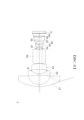
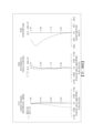
本揭示第一實施例的取像裝置示意圖請參閱第一A圖,像差曲線請參閱第一B圖。第一實施例的取像裝置1包含影像擷取系統鏡片組與電子感光元件IS,影像擷取系統鏡片組由光路的物側至像側依序包含第一透鏡E1、第二透鏡E2、第三透鏡E3、反射元件E9、光圈ST、第四透鏡E4、第五透鏡E5、第六透鏡E6、第七透鏡E7、光闌S1、濾光元件E8與成像面IMG 。Please refer to the first A figure for the schematic diagram of the imaging device of the first embodiment of the present disclosure, and please refer to the first B figure for the aberration curve. The
第一透鏡E1具負屈折力,其材質為玻璃,其物側面於近光軸處為凸面,其像側面於近光軸處為凹面,其物側面及像側面皆為球面(SPH)。The first lens E1 has negative refractive power and is made of glass. Its object side surface is convex near the optical axis, and its image side surface is concave near the optical axis. Both the object side surface and the image side surface are spherical surfaces (SPH).
第二透鏡E2具負屈折力,其材質為塑膠,其物側面於近光軸處為凸面,其像側面於近光軸處為凹面,其物側面及像側面皆為非球面(ASP)。The second lens E2 has negative refractive power and is made of plastic. Its object side surface is convex near the optical axis, and its image side surface is concave near the optical axis. Both the object side surface and the image side surface are aspherical surfaces (ASP).
第三透鏡E3具正屈折力,其材質為塑膠,其物側面於近光軸處為凸面,其像側面於近光軸處為凹面,其物側面及像側面皆為非球面。The third lens E3 has positive refractive power and is made of plastic. Its object side surface is convex near the optical axis, and its image side surface is concave near the optical axis. Both the object side surface and the image side surface are aspherical.
第四透鏡E4具正屈折力,其材質為玻璃,其物側面於近光軸處為凸面,其像側面於近光軸處為凸面,其物側面及像側面皆為非球面。The fourth lens E4 has positive refractive power and is made of glass. Its object-side surface is convex near the optical axis, its image-side surface is convex near the optical axis, and both its object-side surface and image-side surface are aspherical.
第五透鏡E5具負屈折力,其材質為塑膠,其物側面於近光軸處為凸面,其像側面於近光軸處為凹面,其物側面及像側面皆為非球面。The fifth lens E5 has negative refractive power and is made of plastic. Its object side surface is convex near the optical axis, and its image side surface is concave near the optical axis. Both the object side surface and the image side surface are aspherical.
第六透鏡E6具正屈折力,其材質為塑膠,其物側面於近光軸處為凸面,其像側面於近光軸處為凸面,其物側面及像側面皆為非球面。The sixth lens E6 has positive refractive power and is made of plastic. Its object-side surface is convex near the optical axis, and its image-side surface is convex near the optical axis. Both the object-side surface and the image-side surface are aspherical.
第七透鏡E7具負屈折力,其材質為塑膠,其物側面於近光軸處為凹面,其像側面於近光軸處為凹面且於離軸處具有凸面,其物側面及像側面皆為非球面。The seventh lens E7 has negative refractive power and is made of plastic. Its object side surface is concave near the optical axis, its image side surface is concave near the optical axis and has a convex surface off the axis, and both its object side surface and image side surface are aspherical.
濾光元件E8設置於第七透鏡E7與成像面IMG之間,其材質為玻璃且不影響焦距。反射元件E9設置於第三透鏡E3與光圈ST之間,並且反射元件E9為一稜鏡。電子感光元件IS設置於成像面IMG上。The filter element E8 is disposed between the seventh lens E7 and the imaging surface IMG, and its material is glass and does not affect the focal length. The reflective element E9 is disposed between the third lens E3 and the aperture ST, and the reflective element E9 is a prism. The electronic photosensitive element IS is disposed on the imaging surface IMG.
第一實施例詳細的光學數據如表1A所示,曲率半徑、厚度及焦距的單位為毫米,f表示焦距,Fno表示光圈值,HFOV表示最大視角的一半,且表面0-21依序表示由物側至像側的表面。其非球面數據如表1B所示,k表示非球面曲線方程式中的錐面係數,A4-A24則表示各表面第4-24階非球面係數。此外,以下各實施例表格乃對應各實施例的示意圖與像差曲線圖,表格中數據的定義皆與第一實施例的表1A及表1B的定義相同,在此不加贅述。
第一實施例中,影像擷取系統鏡片組的最大像高 ImgH為3.49mm。In the first embodiment, the maximum image height ImgH of the image capture system lens group is 3.49 mm.
第一實施例中,第一透鏡E1物側面與成像面IMG之間於光軸上的距離為TL,影像擷取系統鏡片組1的焦距為f,其關係式為:TL/f=11.59。In the first embodiment, the distance between the object side of the first lens E1 and the imaging surface IMG on the optical axis is TL, and the focal length of the image capture system lens set 1 is f, and the relationship is: TL/f=11.59.
第一實施例中,第一透鏡E1物側面與成像面IMG之間於光軸上的距離為TL,第一透鏡E1物側面至反射元件E9之反射面於光軸上的距離為TLR,其關係式為:TLR/TL=0.53。In the first embodiment, the distance between the object side of the first lens E1 and the imaging surface IMG on the optical axis is TL, and the distance between the object side of the first lens E1 and the reflective surface of the reflective element E9 on the optical axis is TLR, and the relationship is: TLR/TL=0.53.
第一實施例中,第三透鏡E3與第四透鏡E4之間的光軸距離為T34,第三透鏡於光軸上的厚度為CT3,其關係式為:T34/CT3=8.06。In the first embodiment, the optical axis distance between the third lens E3 and the fourth lens E4 is T34, and the thickness of the third lens on the optical axis is CT3, and the relationship is: T34/CT3=8.06.
第一實施例中,第三透鏡E3與第四透鏡E4之間的光軸距離為T34,第一透鏡E1物側面與第七透鏡E7像側面之間於光軸上的距離為TD,其關係式為:T34/TD=0.35。In the first embodiment, the optical axis distance between the third lens E3 and the fourth lens E4 is T34, and the distance between the object side surface of the first lens E1 and the image side surface of the seventh lens E7 on the optical axis is TD, and the relationship is: T34/TD=0.35.
第一實施例中,第五透鏡與第六透鏡之間的光軸距離為T56,第六透鏡E6與第七透鏡E7之間的光軸距離為T67,其關係式為:T67/T56=17.47。In the first embodiment, the optical axis distance between the fifth lens and the sixth lens is T56, and the optical axis distance between the sixth lens E6 and the seventh lens E7 is T67, and the relationship is: T67/T56=17.47.
第一實施例中,影像擷取系統鏡片組的焦距為f,第七透鏡E7的焦距為f7,其關係式為:f/f7=-0.24。In the first embodiment, the focal length of the image capture system lens group is f, and the focal length of the seventh lens E7 is f7, and the relationship is: f/f7=-0.24.
第一實施例中,影像擷取系統鏡片組的焦距為f,第五透鏡E5物側面曲率半徑為R9,其關係式為:f/R9=0.46。In the first embodiment, the focal length of the image capture system lens group is f, and the radius of curvature of the object side surface of the fifth lens E5 is R9, and the relationship is: f/R9=0.46.
第一實施例中,第一透鏡E1、第二透鏡E2與第三透鏡E3的合成焦距為f123,第四透鏡E4、第五透鏡E5、第六透鏡E6與第七透鏡E7的合成焦距為f4567,其關係式為:f123/f4567= -1.53。In the first embodiment, the combined focal length of the first lens E1, the second lens E2 and the third lens E3 is f123, and the combined focal length of the fourth lens E4, the fifth lens E5, the sixth lens E6 and the seventh lens E7 is f4567, and the relationship is: f123/f4567= -1.53.
第一實施例中,第四透鏡E4的焦距為f4,第六透鏡E6與第七透鏡E7之間的光軸距離為T67,其關係式為:f4/T67=2.44。In the first embodiment, the focal length of the fourth lens E4 is f4, and the optical axis distance between the sixth lens E6 and the seventh lens E7 is T67, and the relationship is: f4/T67=2.44.
第一實施例中,第一透鏡E1至第七透鏡E7之間的所有兩相鄰透鏡於光軸上之間隔距離中數值最大者為ATmax1,影像擷取系統鏡片組的焦距為f,其關係式為:ATmax1/f=3.88。In the first embodiment, the maximum value of the distance between all two adjacent lenses between the first lens E1 to the seventh lens E7 on the optical axis is ATmax1, and the focal length of the image capture system lens set is f, and the relationship is: ATmax1/f=3.88.
第一實施例中,第一透鏡E1至第七透鏡E7之間的所有兩相鄰透鏡於光軸上之間隔距離中數值最大者為ATmax1,所述所有兩相鄰透鏡於光軸上之間隔距離中數值第二大者為 ATmax2,其關係式為:ATmax1/ATmax2=2.26。In the first embodiment, the largest value of the distance between all two adjacent lenses between the first lens E1 to the seventh lens E7 on the optical axis is ATmax1, and the second largest value of the distance between all two adjacent lenses on the optical axis is ATmax2, and the relationship is: ATmax1/ATmax2=2.26.
第一實施例中,第二透鏡E2像側面曲率半徑為R4,第五透鏡E5像側面曲率半徑為R10, 第六透鏡E6與第七透鏡E7之間的光軸距離為T67,其關係式為:(R4+R10)/T67=2.57。In the first embodiment, the image side surface curvature radius of the second lens E2 is R4, the image side surface curvature radius of the fifth lens E5 is R10, and the optical axis distance between the sixth lens E6 and the seventh lens E7 is T67, and the relationship is: (R4+R10)/T67=2.57.
第一實施例中,第五透鏡E5物側面曲率半徑為R9,第五透鏡E5像側面曲率半徑為R10,其關係式為:(R9+R10)/(R9-R10)=2.95。In the first embodiment, the radius of curvature of the object side surface of the fifth lens E5 is R9, and the radius of curvature of the image side surface of the fifth lens E5 is R10, and the relationship thereof is: (R9+R10)/(R9-R10)=2.95.
第一實施例中,第七透鏡E7物側面與光軸交點至第七透鏡E7物側面光學有效區邊界與光軸平行之位移量為SAG71,第七透鏡E7於光軸上的厚度為CT7,其關係式為:SAG7R1/CT7= -1.69。In the first embodiment, the displacement from the intersection of the object side of the seventh lens E7 and the optical axis to the boundary of the optical effective area of the object side of the seventh lens E7 parallel to the optical axis is SAG71, and the thickness of the seventh lens E7 on the optical axis is CT7, and the relationship is: SAG7R1/CT7= -1.69.
第一實施例中,第一透鏡E1物側面的最大有效半徑為Y1R1,第五透鏡E5像側面的最大有效半徑為Y5R2,其關係式為:Y1R1/Y5R2=5.38。In the first embodiment, the maximum effective radius of the object side surface of the first lens E1 is Y1R1, and the maximum effective radius of the image side surface of the fifth lens E5 is Y5R2, and the relationship is: Y1R1/Y5R2=5.38.
第一實施例中,第四透鏡E4物側面的最大有效半徑為Y4R1,第七透鏡E7像側面的最大有效半徑為Y7R2,其關係式為:Y7R2/Y4R1=1.83。In the first embodiment, the maximum effective radius of the object side surface of the fourth lens E4 is Y4R1, and the maximum effective radius of the image side surface of the seventh lens E7 is Y7R2, and the relationship is: Y7R2/Y4R1=1.83.
第一實施例中,第一透鏡E1物側面的最大有效半徑為Y1R1,第一透鏡E1像側面的最大有效半徑為Y1R2,第一透鏡E1於光軸上的厚度為CT1,其關係式為:(Y1R1-Y1R2)/CT1=4.81。In the first embodiment, the maximum effective radius of the object side surface of the first lens E1 is Y1R1, the maximum effective radius of the image side surface of the first lens E1 is Y1R2, and the thickness of the first lens E1 on the optical axis is CT1, and the relationship is: (Y1R1-Y1R2)/CT1=4.81.
第一實施例中,第一透鏡E1的折射率N1為1.804。In the first embodiment, the refractive index N1 of the first lens E1 is 1.804.
第一實施例中,第二透鏡E2的阿貝數為V2,第七透鏡E7的阿貝數為V7,其關係式為:V2/V7=2.38。In the first embodiment, the Abbe number of the second lens E2 is V2, and the Abbe number of the seventh lens E7 is V7, and the relationship is: V2/V7=2.38.
第一實施例中, 第六透鏡E6的阿貝數為V6,第七透鏡E7的阿貝數為V7,其關係式為:V6/V7=2.38。In the first embodiment, the Abbe number of the sixth lens E6 is V6, and the Abbe number of the seventh lens E7 is V7, and the relationship between them is: V6/V7=2.38.
《第二實施例》"Second Embodiment"
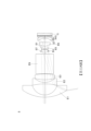
本揭示第二實施例的取像裝置示意圖請參閱第二A圖,像差曲線請參閱第二B圖。第二實施例的取像裝置2包含影像擷取系統鏡片組與電子感光元件IS,影像擷取系統鏡片組由光路的物側至像側依序包含第一透鏡E1、第二透鏡E2、光闌S1、 第三透鏡E3、反射元件E9、光圈ST、第四透鏡E4、第五透鏡E5、第六透鏡E6、光闌S2、第七透鏡E7、濾光元件E8與成像面IMG 。Please refer to the second A figure for the schematic diagram of the imaging device of the second embodiment of the present disclosure, and please refer to the second B figure for the aberration curve. The
第一透鏡E1具負屈折力,其材質為玻璃,其物側面於近光軸處為凸面,其像側面於近光軸處為凹面,其物側面及像側面皆為球面(SPH)。The first lens E1 has negative refractive power and is made of glass. Its object side surface is convex near the optical axis, and its image side surface is concave near the optical axis. Both the object side surface and the image side surface are spherical surfaces (SPH).
第二透鏡E2具負屈折力,其材質為塑膠,其物側面於近光軸處為凹面,其像側面於近光軸處為凹面,其物側面及像側面皆為非球面(ASP)。The second lens E2 has negative refractive power and is made of plastic. Its object side surface is concave near the optical axis, and its image side surface is concave near the optical axis. Both the object side surface and the image side surface are aspherical surfaces (ASP).
第三透鏡E3具正屈折力,其材質為塑膠,其物側面於近光軸處為凸面,其像側面於近光軸處為凸面,其物側面及像側面皆為非球面。The third lens E3 has positive refractive power and is made of plastic. Its object side surface is convex near the optical axis, and its image side surface is convex near the optical axis. Both the object side surface and the image side surface are aspherical.
第四透鏡E4具正屈折力,其材質為塑膠,其物側面於近光軸處為凸面,其像側面於近光軸處為凸面,其物側面及像側面皆為非球面。The fourth lens E4 has positive refractive power and is made of plastic. Its object-side surface is convex near the optical axis, and its image-side surface is convex near the optical axis. Both the object-side surface and the image-side surface are aspherical.
第五透鏡E5具負屈折力,其材質為塑膠,其物側面於近光軸處為凸面,其像側面於近光軸處為凹面,其物側面及像側面皆為非球面。The fifth lens E5 has negative refractive power and is made of plastic. Its object side surface is convex near the optical axis, and its image side surface is concave near the optical axis. Both the object side surface and the image side surface are aspherical.
第六透鏡E6具正屈折力,其材質為塑膠,其物側面於近光軸處為凸面,其像側面於近光軸處為凸面,其物側面及像側面皆為非球面。The sixth lens E6 has positive refractive power and is made of plastic. Its object-side surface is convex near the optical axis, and its image-side surface is convex near the optical axis. Both the object-side surface and the image-side surface are aspherical.
第七透鏡E7具正屈折力,其材質為塑膠,其物側面於近光軸處為凸面,其像側面於近光軸處為凹面且於離軸處具有凸面,其物側面及像側面皆為非球面。The seventh lens E7 has positive refractive power and is made of plastic. Its object side surface is convex near the optical axis, its image side surface is concave near the optical axis and has a convex surface off the axis, and both its object side surface and image side surface are aspherical.
濾光元件E8設置於第七透鏡E7與成像面IMG之間,其材質為玻璃且不影響焦距。反射元件E9設置於第三透鏡E3與光圈ST之間,並且反射元件E9為一稜鏡。電子感光元件IS設置於成像面IMG上。The filter element E8 is disposed between the seventh lens E7 and the imaging surface IMG, and its material is glass and does not affect the focal length. The reflective element E9 is disposed between the third lens E3 and the aperture ST, and the reflective element E9 is a prism. The electronic photosensitive element IS is disposed on the imaging surface IMG.
第二實施例的光學數據如表2A所示,其非球面數據如表2B所示。
第二實施例非球面曲線方程式的表示如同第一實施例的形式。此外,各個關係式的參數係如同第一實施例所闡釋,惟各個關係式的數值係如下表中所列。
《第三實施例》《Third Embodiment》
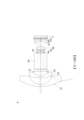
本揭示第三實施例的取像裝置示意圖請參閱第三A圖,像差曲線請參閱第三B圖。第三實施例的取像裝置3包含影像擷取系統鏡片組與電子感光元件IS,影像擷取系統鏡片組由光路的物側至像側依序包含第一透鏡E1、第二透鏡E2、 第三透鏡E3、光闌S1、反射元件E9、光圈ST、第四透鏡E4、第五透鏡E5、第六透鏡E6、第七透鏡E7、濾光元件E8與成像面IMG 。Please refer to FIG3A for the schematic diagram of the imaging device of the third embodiment of the present disclosure, and please refer to FIG3B for the aberration curve. The
第一透鏡E1具負屈折力,其材質為玻璃,其物側面於近光軸處為凸面,其像側面於近光軸處為凹面,其物側面及像側面皆為球面(SPH)。The first lens E1 has negative refractive power and is made of glass. Its object side surface is convex near the optical axis, and its image side surface is concave near the optical axis. Both the object side surface and the image side surface are spherical surfaces (SPH).
第二透鏡E2具負屈折力,其材質為玻璃,其物側面於近光軸處為凸面,其像側面於近光軸處為凹面,其物側面及像側面皆為球面(SPH)。The second lens E2 has negative refractive power and is made of glass. Its object side surface is convex near the optical axis, and its image side surface is concave near the optical axis. Both the object side surface and the image side surface are spherical surfaces (SPH).
第三透鏡E3具正屈折力,其材質為塑膠,其物側面於近光軸處為凹面,其像側面於近光軸處為凸面,其物側面及像側面皆為非球面。The third lens E3 has positive refractive power and is made of plastic. Its object side surface is concave near the optical axis, and its image side surface is convex near the optical axis. Both the object side surface and the image side surface are aspherical.
第四透鏡E4具正屈折力,其材質為玻璃,其物側面於近光軸處為凸面,其像側面於近光軸處為凸面,其物側面及像側面皆為非球面。The fourth lens E4 has positive refractive power and is made of glass. Its object-side surface is convex near the optical axis, its image-side surface is convex near the optical axis, and both its object-side surface and image-side surface are aspherical.
第五透鏡E5具負屈折力,其材質為塑膠,其物側面於近光軸處為凹面,其像側面於近光軸處為凹面,其物側面及像側面皆為非球面。The fifth lens E5 has negative refractive power and is made of plastic. Its object-side surface is concave near the optical axis, and its image-side surface is concave near the optical axis. Both the object-side surface and the image-side surface are aspherical.
第六透鏡E6具正屈折力,其材質為塑膠,其物側面於近光軸處為凸面,其像側面於近光軸處為凸面,其物側面及像側面皆為非球面。The sixth lens E6 has positive refractive power and is made of plastic. Its object-side surface is convex near the optical axis, and its image-side surface is convex near the optical axis. Both the object-side surface and the image-side surface are aspherical.
第七透鏡E7具負屈折力,其材質為塑膠,其物側面於近光軸處為凹面,其像側面於近光軸處為凸面,其物側面及像側面皆為非球面。The seventh lens E7 has negative refractive power and is made of plastic. Its object side surface is concave near the optical axis, and its image side surface is convex near the optical axis. Both the object side surface and the image side surface are aspherical.
濾光元件E8設置於第七透鏡E7與成像面IMG之間,其材質為玻璃且不影響焦距。反射元件E9設置於光闌S1與光圈ST之間,並且反射元件E9為一稜鏡。電子感光元件IS設置於成像面IMG上。The filter element E8 is disposed between the seventh lens E7 and the imaging surface IMG, and its material is glass and does not affect the focal length. The reflective element E9 is disposed between the aperture S1 and the aperture ST, and the reflective element E9 is a prism. The electronic photosensitive element IS is disposed on the imaging surface IMG.
第三實施例的光學數據如表3A所示,其非球面數據如表3B所示。
第三實施例非球面曲線方程式的表示如同第一實施例的形式。此外,各個關係式的參數係如同第一實施例所闡釋,惟各個關係式的數值係如下表中所列。
《第四實施例》《Fourth Embodiment》
本揭示第四實施例的取像裝置示意圖請參閱第四A圖,像差曲線請參閱第四B圖。第四實施例的取像裝置4包含影像擷取系統鏡片組與電子感光元件IS,影像擷取系統鏡片組由光路的物側至像側依序包含第一透鏡E1、第二透鏡E2、 第三透鏡E3、反射元件E9、光圈ST、第四透鏡E4、第五透鏡E5、第六透鏡E6、光闌S1、第七透鏡E7、濾光元件E8與成像面IMG 。Please refer to FIG. 4A for a schematic diagram of the imaging device of the fourth embodiment of the present disclosure, and please refer to FIG. 4B for an aberration curve. The
第一透鏡E1具負屈折力,其材質為玻璃,其物側面於近光軸處為凸面,其像側面於近光軸處為凹面,其物側面及像側面皆為球面(SPH)。The first lens E1 has negative refractive power and is made of glass. Its object side surface is convex near the optical axis, and its image side surface is concave near the optical axis. Both the object side surface and the image side surface are spherical surfaces (SPH).
第二透鏡E2具負屈折力,其材質為玻璃,其物側面於近光軸處為凸面,其像側面於近光軸處為凹面,其物側面及像側面皆為球面(SPH)。The second lens E2 has negative refractive power and is made of glass. Its object side surface is convex near the optical axis, and its image side surface is concave near the optical axis. Both the object side surface and the image side surface are spherical surfaces (SPH).
第三透鏡E3具正屈折力,其材質為塑膠,其物側面於近光軸處為凹面,其像側面於近光軸處為凸面,其物側面及像側面皆為非球面。The third lens E3 has positive refractive power and is made of plastic. Its object side surface is concave near the optical axis, and its image side surface is convex near the optical axis. Both the object side surface and the image side surface are aspherical.
第四透鏡E4具正屈折力,其材質為塑膠,其物側面於近光軸處為凸面,其像側面於近光軸處為凸面,其物側面及像側面皆為非球面。The fourth lens E4 has positive refractive power and is made of plastic. Its object-side surface is convex near the optical axis, and its image-side surface is convex near the optical axis. Both the object-side surface and the image-side surface are aspherical.
第五透鏡E5具負屈折力,其材質為塑膠,其物側面於近光軸處為凸面,其像側面於近光軸處為凹面,其物側面及像側面皆為非球面。The fifth lens E5 has negative refractive power and is made of plastic. Its object side surface is convex near the optical axis, and its image side surface is concave near the optical axis. Both the object side surface and the image side surface are aspherical.
第六透鏡E6具正屈折力,其材質為塑膠,其物側面於近光軸處為凸面,其像側面於近光軸處為凸面,其物側面及像側面皆為非球面。The sixth lens E6 has positive refractive power and is made of plastic. Its object-side surface is convex near the optical axis, and its image-side surface is convex near the optical axis. Both the object-side surface and the image-side surface are aspherical.
第七透鏡E7具負屈折力,其材質為塑膠,其物側面於近光軸處為凹面,其像側面於近光軸處為凹面且於離軸處具有凸面,其物側面及像側面皆為非球面。The seventh lens E7 has negative refractive power and is made of plastic. Its object side surface is concave near the optical axis, its image side surface is concave near the optical axis and has a convex surface off the axis, and both its object side surface and image side surface are aspherical.
濾光元件E8設置於第七透鏡E7與成像面IMG之間,其材質為玻璃且不影響焦距。反射元件E9設置第三透鏡E3與光圈ST之間,並且反射元件E9為一稜鏡。電子感光元件IS設置於成像面IMG上。The filter element E8 is disposed between the seventh lens E7 and the imaging surface IMG, and its material is glass and does not affect the focal length. The reflective element E9 is disposed between the third lens E3 and the aperture ST, and the reflective element E9 is a prism. The electronic photosensitive element IS is disposed on the imaging surface IMG.
第四實施例的光學數據如表4A所示,其非球面數據如表4B所示。
第四實施例非球面曲線方程式的表示如同第一實施例的形式。此外,各個關係式的參數係如同第一實施例所闡釋,惟各個關係式的數值係如下表中所列。
《第五實施例》"Fifth Embodiment"
本揭示第五實施例的取像裝置示意圖請參閱第五A圖,像差曲線請參閱第五B圖。第五實施例的取像裝置5包含影像擷取系統鏡片組與電子感光元件IS,影像擷取系統鏡片組由光路的物側至像側依序包含第一透鏡E1、第二透鏡E2、 第三透鏡E3、反射元件E9、光圈ST、第四透鏡E4、第五透鏡E5、光闌S1、第六透鏡E6、第七透鏡E7、濾光元件E8與成像面IMG 。Please refer to FIG5A for the schematic diagram of the imaging device of the fifth embodiment of the present disclosure, and please refer to FIG5B for the aberration curve. The imaging device 5 of the fifth embodiment includes an image capturing system lens set and an electronic photosensitive element IS. The image capturing system lens set includes a first lens E1, a second lens E2, a third lens E3, a reflective element E9, an aperture ST, a fourth lens E4, a fifth lens E5, a stop S1, a sixth lens E6, a seventh lens E7, a filter element E8 and an imaging surface IMG in order from the object side to the image side of the optical path.
第一透鏡E1具負屈折力,其材質為玻璃,其物側面於近光軸處為凸面,其像側面於近光軸處為凹面,其物側面及像側面皆為球面(SPH)。The first lens E1 has negative refractive power and is made of glass. Its object side surface is convex near the optical axis, and its image side surface is concave near the optical axis. Both the object side surface and the image side surface are spherical surfaces (SPH).
第二透鏡E2具負屈折力,其材質為玻璃,其物側面於近光軸處為凹面,其像側面於近光軸處為凹面,其物側面及像側面皆為球面(SPH)。The second lens E2 has negative refractive power and is made of glass. Its object side surface is concave near the optical axis, and its image side surface is concave near the optical axis. Both the object side surface and the image side surface are spherical surfaces (SPH).
第三透鏡E3具正屈折力,其材質為玻璃,其物側面於近光軸處為凸面,其像側面於近光軸處為凸面,其物側面及像側面皆為球面。The third lens E3 has positive refractive power and is made of glass. Its object side surface is convex near the optical axis, its image side surface is convex near the optical axis, and both its object side surface and image side surface are spherical.
第四透鏡E4具正屈折力,其材質為塑膠,其物側面於近光軸處為凸面,其像側面於近光軸處為凸面,其物側面及像側面皆為非球面。The fourth lens E4 has positive refractive power and is made of plastic. Its object-side surface is convex near the optical axis, and its image-side surface is convex near the optical axis. Both the object-side surface and the image-side surface are aspherical.
第五透鏡E5具負屈折力,其材質為塑膠,其物側面於近光軸處為凸面,其像側面於近光軸處為凹面,其物側面及像側面皆為非球面。The fifth lens E5 has negative refractive power and is made of plastic. Its object side surface is convex near the optical axis, and its image side surface is concave near the optical axis. Both the object side surface and the image side surface are aspherical.
第六透鏡E6具正屈折力,其材質為玻璃,其物側面於近光軸處為凸面,其像側面於近光軸處為凸面,其物側面及像側面皆為非球面。The sixth lens E6 has positive refractive power and is made of glass. Its object-side surface is convex near the optical axis, and its image-side surface is convex near the optical axis. Both the object-side surface and the image-side surface are aspherical.
第七透鏡E7具負屈折力,其材質為塑膠,其物側面於近光軸處為凸面,其像側面於近光軸處為凹面且於離軸處具有凸面,其物側面及像側面皆為非球面。The seventh lens E7 has negative refractive power and is made of plastic. Its object side surface is convex near the optical axis, its image side surface is concave near the optical axis and has a convex surface off the axis, and both its object side surface and image side surface are aspherical.
濾光元件E8設置於第七透鏡E7與成像面IMG之間,其材質為玻璃且不影響焦距。反射元件E9設置第三透鏡E3與光圈ST之間,並且反射元件E9為一稜鏡。電子感光元件IS設置於成像面IMG上。The filter element E8 is disposed between the seventh lens E7 and the imaging surface IMG, and its material is glass and does not affect the focal length. The reflective element E9 is disposed between the third lens E3 and the aperture ST, and the reflective element E9 is a prism. The electronic photosensitive element IS is disposed on the imaging surface IMG.
第五實施例的光學數據如表5A所示,其非球面數據如表5B所示。
第五實施例非球面曲線方程式的表示如同第一實施例的形式。此外,各個關係式的參數係如同第一實施例所闡釋,惟各個關係式的數值係如下表中所列。
《第六實施例》"Sixth Embodiment"
本揭示第六實施例的取像裝置示意圖請參閱第六A圖,像差曲線請參閱第六B圖。第六實施例的取像裝置6包含影像擷取系統鏡片組與電子感光元件IS,影像擷取系統鏡片組由光路的物側至像側依序包含第一透鏡E1、第二透鏡E2、 光闌S1、第三透鏡E3、反射元件E9、光圈ST、第四透鏡E4、第五透鏡E5、第六透鏡E6、第七透鏡E7、濾光元件E8與成像面IMG 。Please refer to FIG6A for the schematic diagram of the imaging device of the sixth embodiment of the present disclosure, and please refer to FIG6B for the aberration curve. The
第一透鏡E1具負屈折力,其材質為玻璃,其物側面於近光軸處為凸面,其像側面於近光軸處為凹面,其物側面及像側面皆為球面(SPH)。The first lens E1 has negative refractive power and is made of glass. Its object side surface is convex near the optical axis, and its image side surface is concave near the optical axis. Both the object side surface and the image side surface are spherical surfaces (SPH).
第二透鏡E2具負屈折力,其材質為塑膠,其物側面於近光軸處為凸面,其像側面於近光軸處為凹面,其物側面及像側面皆為非球面(ASP)。The second lens E2 has negative refractive power and is made of plastic. Its object side surface is convex near the optical axis, and its image side surface is concave near the optical axis. Both the object side surface and the image side surface are aspherical surfaces (ASP).
第三透鏡E3具正屈折力,其材質為塑膠,其物側面於近光軸處為凸面,其像側面於近光軸處為凸面,其物側面及像側面皆為非球面。The third lens E3 has positive refractive power and is made of plastic. Its object side surface is convex near the optical axis, and its image side surface is convex near the optical axis. Both the object side surface and the image side surface are aspherical.
第四透鏡E4具正屈折力,其材質為塑膠,其物側面於近光軸處為凸面,其像側面於近光軸處為凸面,其物側面及像側面皆為非球面。The fourth lens E4 has positive refractive power and is made of plastic. Its object-side surface is convex near the optical axis, and its image-side surface is convex near the optical axis. Both the object-side surface and the image-side surface are aspherical.
第五透鏡E5具負屈折力,其材質為塑膠,其物側面於近光軸處為凸面,其像側面於近光軸處為凹面,其物側面及像側面皆為非球面。The fifth lens E5 has negative refractive power and is made of plastic. Its object side surface is convex near the optical axis, and its image side surface is concave near the optical axis. Both the object side surface and the image side surface are aspherical.
第六透鏡E6具正屈折力,其材質為玻璃,其物側面於近光軸處為凸面,其像側面於近光軸處為凸面,其物側面及像側面皆為非球面。The sixth lens E6 has positive refractive power and is made of glass. Its object-side surface is convex near the optical axis, and its image-side surface is convex near the optical axis. Both the object-side surface and the image-side surface are aspherical.
第七透鏡E7具負屈折力,其材質為塑膠,其物側面於近光軸處為凸面,其像側面於近光軸處為凹面且於離軸處具有凸面,其物側面及像側面皆為非球面。The seventh lens E7 has negative refractive power and is made of plastic. Its object side surface is convex near the optical axis, its image side surface is concave near the optical axis and has a convex surface off the axis, and both its object side surface and image side surface are aspherical.
濾光元件E8設置於第七透鏡E7與成像面IMG之間,其材質為玻璃且不影響焦距。反射元件E9設置第三透鏡E3與光圈ST之間,並且反射元件E9為一稜鏡。電子感光元件IS設置於成像面IMG上。The filter element E8 is disposed between the seventh lens E7 and the imaging surface IMG, and its material is glass and does not affect the focal length. The reflective element E9 is disposed between the third lens E3 and the aperture ST, and the reflective element E9 is a prism. The electronic photosensitive element IS is disposed on the imaging surface IMG.
第六實施例的光學數據如表6A所示,其非球面數據如表6B所示。
第六實施例非球面曲線方程式的表示如同第一實施例的形式。此外,各個關係式的參數係如同第一實施例所闡釋,惟各個關係式的數值係如下表中所列。
《第七實施例》Seventh Embodiment
本揭示第七實施例的取像裝置示意圖請參閱第七A圖,像差曲線請參閱第七B圖。第七實施例的取像裝置7包含影像擷取系統鏡片組與電子感光元件IS,影像擷取系統鏡片組由光路的物側至像側依序包含第一透鏡E1、第二透鏡E2、 第三透鏡E3、反射元件E9、光圈ST、第四透鏡E4、第五透鏡E5、第六透鏡E6、光闌S1、第七透鏡E7、濾光元件E8與成像面IMG 。Please refer to FIG. 7A for the schematic diagram of the imaging device of the seventh embodiment of the present disclosure, and please refer to FIG. 7B for the aberration curve. The
第一透鏡E1具負屈折力,其材質為玻璃,其物側面於近光軸處為凸面,其像側面於近光軸處為凹面,其物側面及像側面皆為球面(SPH)。The first lens E1 has negative refractive power and is made of glass. Its object side surface is convex near the optical axis, and its image side surface is concave near the optical axis. Both the object side surface and the image side surface are spherical surfaces (SPH).
第二透鏡E2具負屈折力,其材質為玻璃,其物側面於近光軸處為凸面,其像側面於近光軸處為凹面,其物側面及像側面皆為球面(SPH)。The second lens E2 has negative refractive power and is made of glass. Its object side surface is convex near the optical axis, and its image side surface is concave near the optical axis. Both the object side surface and the image side surface are spherical surfaces (SPH).
第三透鏡E3具正屈折力,其材質為塑膠,其物側面於近光軸處為凹面,其像側面於近光軸處為凸面,其物側面及像側面皆為非球面。The third lens E3 has positive refractive power and is made of plastic. Its object side surface is concave near the optical axis, and its image side surface is convex near the optical axis. Both the object side surface and the image side surface are aspherical.
第四透鏡E4具正屈折力,其材質為塑膠,其物側面於近光軸處為凸面,其像側面於近光軸處為凸面,其物側面及像側面皆為非球面。The fourth lens E4 has positive refractive power and is made of plastic. Its object-side surface is convex near the optical axis, and its image-side surface is convex near the optical axis. Both the object-side surface and the image-side surface are aspherical.
第五透鏡E5具負屈折力,其材質為塑膠,其物側面於近光軸處為凸面,其像側面於近光軸處為凹面,其物側面及像側面皆為非球面。The fifth lens E5 has negative refractive power and is made of plastic. Its object side surface is convex near the optical axis, and its image side surface is concave near the optical axis. Both the object side surface and the image side surface are aspherical.
第六透鏡E6具正屈折力,其材質為塑膠,其物側面於近光軸處為凸面,其像側面於近光軸處為凸面,其物側面及像側面皆為非球面。The sixth lens E6 has positive refractive power and is made of plastic. Its object-side surface is convex near the optical axis, and its image-side surface is convex near the optical axis. Both the object-side surface and the image-side surface are aspherical.
第七透鏡E7具負屈折力,其材質為塑膠,其物側面於近光軸處為凹面,其像側面於近光軸處為凹面且於離軸處具有凸面,其物側面及像側面皆為非球面。The seventh lens E7 has negative refractive power and is made of plastic. Its object side surface is concave near the optical axis, its image side surface is concave near the optical axis and has a convex surface off the axis, and both its object side surface and image side surface are aspherical.
濾光元件E8設置於第七透鏡E7與成像面IMG之間,其材質為玻璃且不影響焦距。反射元件E9設置第三透鏡E3與光圈ST之間,並且反射元件E9為一稜鏡。電子感光元件IS設置於成像面IMG上。The filter element E8 is disposed between the seventh lens E7 and the imaging surface IMG, and its material is glass and does not affect the focal length. The reflective element E9 is disposed between the third lens E3 and the aperture ST, and the reflective element E9 is a prism. The electronic photosensitive element IS is disposed on the imaging surface IMG.
第七實施例的光學數據如表7A所示,其非球面數據如表7B所示。
第七實施例非球面曲線方程式的表示如同第一實施例的形式。此外,各個關係式的參數係如同第一實施例所闡釋,惟各個關係式的數值係如下表中所列。
《第八實施例》"Eighth Embodiment"
本揭示第八實施例的取像裝置示意圖請參閱第八A圖,像差曲線請參閱第八B圖。第八實施例的取像裝置8包含影像擷取系統鏡片組與電子感光元件IS,影像擷取系統鏡片組由光路的物側至像側依序包含第一透鏡E1、第二透鏡E2、 第三透鏡E3、反射元件E9、光圈ST、第四透鏡E4、第五透鏡E5、第六透鏡E6、光闌S1、第七透鏡E7、濾光元件E8與成像面IMG 。Please refer to FIG8A for the schematic diagram of the imaging device of the eighth embodiment of the present disclosure, and please refer to FIG8B for the aberration curve. The
第一透鏡E1具負屈折力,其材質為玻璃,其物側面於近光軸處為凹面,其像側面於近光軸處為凹面,其物側面及像側面皆為非球面(ASP)。The first lens E1 has negative refractive power and is made of glass. Its object side surface is concave near the optical axis, and its image side surface is concave near the optical axis. Both the object side surface and the image side surface are aspherical surfaces (ASP).
第二透鏡E2具負屈折力,其材質為塑膠,其物側面於近光軸處為凹面,其像側面於近光軸處為凹面,其物側面及像側面皆為非球面。The second lens E2 has negative refractive power and is made of plastic. Its object side surface is concave near the optical axis, and its image side surface is concave near the optical axis. Both the object side surface and the image side surface are aspherical.
第三透鏡E3具正屈折力,其材質為塑膠,其物側面於近光軸處為凸面,其像側面於近光軸處為凸面,其物側面及像側面皆為非球面。The third lens E3 has positive refractive power and is made of plastic. Its object side surface is convex near the optical axis, and its image side surface is convex near the optical axis. Both the object side surface and the image side surface are aspherical.
第四透鏡E4具正屈折力,其材質為塑膠,其物側面於近光軸處為凸面,其像側面於近光軸處為凸面,其物側面及像側面皆為非球面。The fourth lens E4 has positive refractive power and is made of plastic. Its object-side surface is convex near the optical axis, and its image-side surface is convex near the optical axis. Both the object-side surface and the image-side surface are aspherical.
第五透鏡E5具負屈折力,其材質為塑膠,其物側面於近光軸處為凸面,其像側面於近光軸處為凹面,其物側面及像側面皆為非球面。The fifth lens E5 has negative refractive power and is made of plastic. Its object side surface is convex near the optical axis, and its image side surface is concave near the optical axis. Both the object side surface and the image side surface are aspherical.
第六透鏡E6具正屈折力,其材質為塑膠,其物側面於近光軸處為凸面,其像側面於近光軸處為凸面,其物側面及像側面皆為非球面。The sixth lens E6 has positive refractive power and is made of plastic. Its object-side surface is convex near the optical axis, and its image-side surface is convex near the optical axis. Both the object-side surface and the image-side surface are aspherical.
第七透鏡E7具負屈折力,其材質為塑膠,其物側面於近光軸處為凹面,其像側面於近光軸處為凹面且於離軸處具有凸面,其物側面及像側面皆為非球面。The seventh lens E7 has negative refractive power and is made of plastic. Its object side surface is concave near the optical axis, its image side surface is concave near the optical axis and has a convex surface off the axis, and both its object side surface and image side surface are aspherical.
濾光元件E8設置於第七透鏡E7與成像面IMG之間,其材質為玻璃且不影響焦距。反射元件E9設置第三透鏡E3與光圈ST之間,並且反射元件E9為一稜鏡。電子感光元件IS設置於成像面IMG上。The filter element E8 is disposed between the seventh lens E7 and the imaging surface IMG, and its material is glass and does not affect the focal length. The reflective element E9 is disposed between the third lens E3 and the aperture ST, and the reflective element E9 is a prism. The electronic photosensitive element IS is disposed on the imaging surface IMG.
第八實施例的光學數據如表8A所示,其非球面數據如表8B所示。
第八實施例非球面曲線方程式的表示如同第一實施例的形式。此外,各個關係式的參數係如同第一實施例所闡釋,惟各個關係式的數值係如下表中所列。
《第九實施例》Ninth Embodiment
請參照第十二圖,係繪示依照本揭示第九實施例的一種取像裝置100的立體示意圖。由第十二圖可知,在本實施例中取像裝置100為一相機模組。取像裝置100包含攝影光學鏡片系統101、驅動裝置102以及電子感光元件103,其中攝影光學鏡片系統101包含本揭示第一實施例的影像擷取系統鏡片組 以及一承載影像擷取系統鏡片組的鏡筒(未另標號)。取像裝置100利用攝影光學鏡片系統101聚光產生影像,並配合驅動裝置102進行影像對焦,最後成像於電子感光元件103(即第一實施例的電子感光元件IS)上,並將影像資料輸出。Please refer to FIG. 12, which is a three-dimensional schematic diagram of an
驅動裝置102可為自動對焦(Auto-Focus)模組,其驅動方式可使用如音圈馬達(Voice Coil Motor, VCM)、微機電系統(Micro Electro-Mechanical Systems, MEMS)、壓電系統(Piezoelectric)、以及記憶金屬 (Shape Memory Alloy)等驅動系統。驅動裝置102可讓攝影光學鏡片系統101 取得較佳的成像位置,可提供被攝物於不同物距的狀態下,皆能拍攝清晰影像。The
取像裝置100可搭載一感光度佳及低雜訊的電子感光元件103(如CMOS、CCD)設置於攝影光學鏡片系統101的成像面,可真實呈現攝影光學鏡片系統101的良好成像品質。The
此外,取像裝置100更可包含影像穩定模組104,其可為加速計、陀螺儀或霍爾元件(Hall Effect Sensor)等動能感測元件,而第九實施例中,影像穩定模組104為陀螺儀,但不以此為限。藉由調整攝影光學鏡片系統101不同軸向的變化以補償拍攝瞬間因晃動而產生的模糊影像,進一步提升動態以及低照度場景拍攝的成像品質,並提供例如光學防手震(Optical Image Stabilization;OIS)、電子防手震(Electronic Image Stabilization;EIS)等進階的影像補償功能。In addition, the
本揭示的取像裝置100並不以應用於智慧型手機為限。取像裝置100更可視需求應用於移動對焦的系統,並兼具優良像差修正與良好成像品質的特色。舉例來說,取像裝置100可多方面應用於車用電子裝置、無人機、智慧型電子產品、平板電腦、可穿戴裝置、醫療器材、精密儀器、監視攝影機、隨身影像紀錄器、辨識系統、多鏡頭裝置、體感偵測、虛擬實境、運動裝置與家庭智能輔助系統等電子裝置中。The
《第十實施例》"Tenth Embodiment"
請參照第十三A圖及第十三B圖,其中第十三A圖為本揭示第十實施例的電子裝置200前視圖,第十三B圖為第十三A圖的電子裝置200後視圖。在本實施例中,電子裝置200為一智慧型手機。如第十三A圖所示,電子裝置200的正面包含顯示裝置210、TOF(Time of Flight,飛時測距)模組201、取像裝置202及取像裝置203。取像裝置202、取像裝置203位於顯示裝置210上方,面向同一方向且水平排列於電子裝置200的上緣。取像裝置202係超廣角取像裝置,取像裝置203係廣角取像裝置。取像裝置202的視角大於取像裝置203的視角至少30度。Please refer to FIG. 13A and FIG. 13B, wherein FIG. 13A is a front view of the
如第十三B圖所示,電子裝置200的背面包含閃光燈模組240、取像裝置234及取像裝置236。取像裝置234及取像裝置236面向同一方向,並垂直排列於電子裝置200的背面。取像裝置234為超廣角取像裝置,取像裝置236為廣角取像裝置,採用本揭示的影像擷取系統鏡片組。取像裝置234的視角大於取像裝置236的視角至少20度。As shown in FIG. 13B, the back of the
《第十一實施例》"Eleventh Embodiment"
請參照第十四圖,第十四圖為本揭示第十一實施例的電子裝置300後視圖。如第十四圖所示,電子裝置300的背面包含閃光燈模組340、取像裝置332、取像裝置334及取像裝置336。取像裝置332、取像裝置334及取像裝置336面向同一方向,並垂直排列於電子裝置300的背面。閃光燈模組340設置於電子裝置300的背面上緣,位於取像裝置336的附近。取像裝置336為超廣角取像裝置,取像裝置334為廣角取像裝置,採用本揭示的影像擷取系統鏡片組,取像裝置332為望遠取像裝置。取像裝置336的視角大於取像裝置334的視角至少20度,而取像裝置334的視角大於取像裝置332的視角至少20度,使得電子裝置300背面的取像裝置中視角最大的取像裝置336的視角大於視角最小的取像裝置332的視角至少40度。Please refer to FIG. 14, which is a rear view of the
《第十二實施例》"Twelfth Embodiment"
請參照第十五圖,第十五圖為本揭示第十二實施例的電子裝置400後視圖。如第十五圖所示,電子裝置400的背面包含TOF(Time of Flight,飛時測距)模組407、閃光燈模組408、取像裝置404a、取像裝置404b、取像裝置405a、取像裝置405b、取像裝置406a、取像裝置406b、取像裝置409a及取像裝置409b。取像裝置404a、取像裝置404b、取像裝置405a、取像裝置405b、取像裝置406a、取像裝置406b、取像裝置409a及取像裝置409b面向同一方向,並分成兩排垂直排列於電子裝置400的背面。TOF(Time of Flight,飛時測距)模組407及閃光燈模組408設置於電子裝置400的背面上緣,位於取像裝置406a的附近。取像裝置405a、405b為超廣角取像裝置,取像裝置404a、404b為廣角取像裝置,採用本發明的成像光學系統鏡組,取像裝置406a、406b為望遠取像裝置,取像裝置409a、409b為具有轉折光路的望遠取像裝置。取像裝置405a、405b的視角大於取像裝置404a、404b的視角至少30度,而取像裝置404a、404b的視角大於取像裝置406a、406b、409a、409b的視角至少30度。Please refer to FIG. 15, which is a rear view of the
《第十三實施例》"Thirteenth Embodiment"
請參照第十六A圖至第十六B圖,其中第十六A圖為本揭示第十三實施例的電子裝置500前視圖,第十六B圖為第十六A圖的電子裝置500後視圖。在本實施例中,電子裝置500為一智慧型手機。Please refer to FIG. 16A to FIG. 16B, wherein FIG. 16A is a front view of the
如第十六A圖所示,電子裝置500的正面包含顯示裝置510及取像裝置520,其中取像裝置520採用本揭示影像擷取系統鏡片組。 如第十二B圖所示,電子裝置400的背面包含望遠鏡頭530、廣角鏡頭540、超廣角鏡頭550。As shown in FIG. 16A , the front of the
《第十四實施例》《Fourteenth Embodiment》
請參照第十七圖,係為本揭示第十四實施例的電子裝置600側視剖面示意圖。電子裝置600包含兩組相對配置的取像裝置1’,該配置可利於拍攝360度全景影像,可應用於運動攝影或生活影像紀錄等,且其中一組取像裝置1’第一透鏡物側面中心至另一組取像裝置1’第一透鏡物側面中心距離為Da,其滿足關係式:Da < 40 [mm]。Please refer to FIG. 17, which is a schematic side cross-sectional view of the
前揭電子裝置僅是示範性地說明本發明的實際運用例子,並非限制本發明之取像裝置的運用範圍。較佳地,電子裝置可進一步包含控制單元、顯示單元、儲存單元、暫儲存單元(RAM)或其組合。The aforementioned electronic device is merely an example of the actual application of the present invention, and does not limit the application scope of the imaging device of the present invention. Preferably, the electronic device may further include a control unit, a display unit, a storage unit, a temporary storage unit (RAM) or a combination thereof.
以上各表所示為本發明的實施例中,影像擷取系統鏡片組的不同數值變化表,然本發明各個實施例的數值變化皆屬實驗所得,即使使用不同數值,相同結構的產品仍應屬於本發明揭露的保護範疇,故以上的說明所描述的及圖式僅做為例示性,非用以限制本發明揭露的申請專利範圍。The above tables show different numerical value variations of the lens assembly of the image capture system in the embodiments of the present invention. However, the numerical value variations of each embodiment of the present invention are obtained through experiments. Even if different numerical values are used, products with the same structure should still fall within the scope of protection disclosed by the present invention. Therefore, the above descriptions and drawings are only for illustrative purposes and are not intended to limit the scope of the patent application disclosed by the present invention.
取像裝置 1、1’、2、3、4、5、6、7、8 第一透鏡 E1 第二透鏡 E2 第三透鏡 E3 第四透鏡 E4 第五透鏡 E5 第六透鏡 E6 第七透鏡 E7 濾光元件 E8 反射元件 E9、E9’ 光圈 ST 光欄 S1、S2 成像面 IMG 電子感光元件 IS 光軸 OO’、OO’O’’ 長軸有效半徑 D、D’ 短軸有效半徑 L、L’ 取像裝置 100、202、203、234、236、332、334、336、404a、404b、405a、405b、406a、406b、409a、409b 攝影光學鏡片系統 101 驅動裝置 102 電子感光元件 103 電子裝置 200、300、400、500、600 TOF模組 201、407 顯示裝置 210、510 取像裝置 332、334、336、404a、404b、405a、405b、406a、406b、409a、409b 閃光燈模組 240、340、408 望遠鏡頭 530 廣角鏡頭 540 超廣角鏡頭 550 第二透鏡像側面曲率半徑 R4 第五透鏡物側面曲率半徑 R9 第五透鏡像側面曲率半徑 R10 影像擷取系統鏡片組的焦距 f 第四透鏡焦距 f4 第七透鏡焦距 f7 第一透鏡、第二透鏡與第三透鏡的合成焦距 f123 第四透鏡、第五透鏡、第六透鏡與第七透鏡的合成焦距 f4567 第一透鏡物側面與一成像面之間於光軸上的距離 TL 第一透鏡物側面至一反射元件之反射面於光軸上的距離 TLR 第一透鏡物側面與第七透鏡像側面之間於光軸上的距離 TD 影像擷取系統鏡片組光圈值 Fno 影像擷取系統鏡片組中最大視角的一半 HFOV 影像擷取系統鏡片組的最大像高 ImgH 第一透鏡至第七透鏡之間的所有兩相鄰透鏡於光軸上之間隔距離中數值最大者ATmax1 第一透鏡至第七透鏡之間的所有兩相鄰透鏡於光軸上之間隔距離中數值第二大者 ATmax2 第一透鏡物側面的最大有效半徑 Y1R1 第一透鏡像側面的最大有效半徑 Y1R2 第五透鏡像側面的最大有效半徑 Y5R2 第四透鏡物側面的最大有效半徑 Y4R1 第七透鏡像側面的最大有效半徑 Y7R2 第六透鏡阿貝數 V6 第七透鏡阿貝數 V7 第三透鏡與第四透鏡之間的光軸距離 T34 第五透鏡與第六透鏡之間的光軸距離 T56 第六透鏡與第七透鏡之間的光軸距離 T67 第七透鏡物側面與光軸交點至第七透鏡物側面光學有效區邊界與光軸平行之位移量 SAG71 第一透鏡於光軸上的厚度 CT1 第三透鏡於光軸上的厚度 CT3 第七透鏡於光軸上的厚度 CT7 取像裝置第一透鏡物側面中心至另一組取像裝置第一透鏡物側面中心距離 Da 第一透鏡折射率 N1 Image acquisition device 1, 1’, 2, 3, 4, 5, 6, 7, 8 First lens E1 Second lens E2 Third lens E3 Fourth lens E4 Fifth lens E5 Sixth lens E6 Seventh lens E7 Filter element E8 Reflection element E9, E9’ Aperture ST Light bar S1, S2 Imaging surface IMG Electronic photosensitive element IS Optical axis OO’, OO’O’’ Effective radius of major axis D, D’ Effective radius of minor axis L, L’ Image acquisition device 100, 202, 203, 234, 236, 332, 334, 336, 404a, 404b, 405a, 405b, 406a, 406b, 409a, 409b Photographic optical lens system 101 Driving device 102 Electronic photosensitive element 103 Electronic device 200, 300, 400, 500, 600 TOF module 201, 407 Display device 210, 510 Image acquisition device 332, 334, 336, 404a, 404b, 405a, 405b, 406a, 406b, 409a, 409b Flash module 240, 340, 408 Telephoto lens 530 Wide-angle lens 540 Super wide-angle lens 550 Second lens image side curvature radius R4 Fifth lens object side curvature radius R9 Fifth lens image side curvature radius R10 Focal length of the image capture system lens group f Focal length of the fourth lens f4 Focal length of the seventh lens f7 Composite focal length of the first lens, the second lens and the third lens f123 Composite focal length of the fourth lens, the fifth lens, the sixth lens and the seventh lens f4567 Distance on the optical axis between the object side of the first lens and an imaging surface TL Distance on the optical axis between the object side of the first lens and the reflection surface of a reflection element TLR Distance on the optical axis between the object side of the first lens and the image side of the seventh lens TD Image capture system lens group aperture value Fno Half of the maximum viewing angle in the image capture system lens group HFOV Maximum image height of the image capture system lens group ImgH The largest value among all the distances between two adjacent lenses on the optical axis between the first lens to the seventh lens ATmax1 The second largest value among all the distances between two adjacent lenses on the optical axis between the first lens to the seventh lens ATmax2 Maximum effective radius of the object side of the first lens Y1R1 Maximum effective radius of the image side of the first lens Y1R2 Maximum effective radius of the image side of the fifth lens Y5R2 Maximum effective radius of the object side of the fourth lens Y4R1 Maximum effective radius of the image side of the seventh lens Y7R2 Abbe number of the sixth lens V6 Abbe number of the seventh lens V7 Optical axis distance between the third lens and the fourth lens T34 Optical axis distance between the fifth lens and the sixth lens T56 Optical axis distance between the sixth lens and the seventh lens T67 Displacement from the intersection of the seventh lens object side and the optical axis to the boundary of the optical effective area of the seventh lens object side parallel to the optical axis SAG71 Thickness of the first lens on the optical axis CT1 Thickness of the third lens on the optical axis CT3 Thickness of the seventh lens on the optical axis CT7 Distance from the center of the object side of the first lens of the imaging device to the center of the object side of the first lens of another imaging device Da Refractive index of the first lens N1
第一A圖係本揭示第一實施例的取像裝置示意圖。 第一B圖係本揭示第一實施例的像差曲線圖。 第二A圖係本揭示第二實施例的取像裝置示意圖。 第二B圖係本揭示第二實施例的像差曲線圖。 第三A圖係本揭示第三實施例的取像裝置示意圖。 第三B圖係本揭示第三實施例的像差曲線圖。 第四A圖係本揭示第四實施例的取像裝置示意圖。 第四B圖係本揭示第四實施例的像差曲線圖。 第五A圖係本揭示第五實施例的取像裝置示意圖。 第五B圖係本揭示第五實施例的像差曲線圖。 第六A圖係本揭示第六實施例的取像裝置示意圖。 第六B圖係本揭示第六實施例的像差曲線圖。 第七A圖係本揭示第七實施例的取像裝置示意圖。 第七B圖係本揭示第七實施例的像差曲線圖。 第八A圖係本揭示第八實施例的取像裝置示意圖。 第八B圖係本揭示第八實施例的像差曲線圖。 第九圖係以本揭示第一實施例作為範例說明影像擷取系統鏡片組的參數SAG7R1、Y1R1、Y1R2、Y4R1、Y5R2、Y7R2的示意圖。 第十A圖係以本揭示第一實施例作為範例說明影像擷取系統鏡片組的參數TL的示意圖。 第十B圖係以本揭示第一實施例的變化例作為範例說明具光軸轉折配置的影像擷取系統鏡片組的參數TLR的示意圖。 第十一A圖係本揭示非圓形光圈的示意圖。 第十一B圖係本揭示另一非圓形光圈的示意圖。 第十二圖係本揭示第一實施例取像裝置的立體示意圖。 第十三A圖係本揭示第九實施例的電子裝置前視圖。 第十三B圖係本揭示第九實施例的電子裝置後視圖。 第十四圖係本揭示第十實施例的電子裝置後視圖。 第十五圖係本揭示第十一實施例的電子裝置後視圖。 第十六A圖係本揭示第十二實施例的電子裝置前視圖。 第十六B圖係本揭示第十二實施例的電子裝置後視圖。 第十七圖係本揭示第十三實施例的電子裝置側視剖面示意圖。 The first A figure is a schematic diagram of the imaging device of the first embodiment of the present disclosure. The first B figure is an aberration curve diagram of the first embodiment of the present disclosure. The second A figure is a schematic diagram of the imaging device of the second embodiment of the present disclosure. The second B figure is an aberration curve diagram of the second embodiment of the present disclosure. The third A figure is a schematic diagram of the imaging device of the third embodiment of the present disclosure. The third B figure is an aberration curve diagram of the third embodiment of the present disclosure. The fourth A figure is a schematic diagram of the imaging device of the fourth embodiment of the present disclosure. The fourth B figure is an aberration curve diagram of the fourth embodiment of the present disclosure. The fifth A figure is a schematic diagram of the imaging device of the fifth embodiment of the present disclosure. The fifth B figure is an aberration curve diagram of the fifth embodiment of the present disclosure. The sixth A figure is a schematic diagram of the imaging device of the sixth embodiment of the present disclosure. The sixth B figure is an aberration curve diagram of the sixth embodiment of the present disclosure. FIG. 7A is a schematic diagram of an imaging device of the seventh embodiment of the present disclosure. FIG. 7B is an aberration curve diagram of the seventh embodiment of the present disclosure. FIG. 8A is a schematic diagram of an imaging device of the eighth embodiment of the present disclosure. FIG. 8B is an aberration curve diagram of the eighth embodiment of the present disclosure. FIG. 9 is a schematic diagram of parameters SAG7R1, Y1R1, Y1R2, Y4R1, Y5R2, and Y7R2 of an image capture system lens set using the first embodiment of the present disclosure as an example. FIG. 10A is a schematic diagram of parameters TL of an image capture system lens set using the first embodiment of the present disclosure as an example. FIG. 10B is a schematic diagram of parameters TLR of an image capture system lens set with an optical axis turning configuration using a variation of the first embodiment of the present disclosure as an example. Figure 11A is a schematic diagram of a non-circular aperture of the present disclosure. Figure 11B is a schematic diagram of another non-circular aperture of the present disclosure. Figure 12 is a three-dimensional schematic diagram of the imaging device of the first embodiment of the present disclosure. Figure 13A is a front view of the electronic device of the ninth embodiment of the present disclosure. Figure 13B is a rear view of the electronic device of the ninth embodiment of the present disclosure. Figure 14 is a rear view of the electronic device of the tenth embodiment of the present disclosure. Figure 15 is a rear view of the electronic device of the eleventh embodiment of the present disclosure. Figure 16A is a front view of the electronic device of the twelfth embodiment of the present disclosure. Figure 16B is a rear view of the electronic device of the twelfth embodiment of the present disclosure. Figure 17 is a side cross-sectional schematic diagram of the electronic device of the thirteenth embodiment of the present disclosure.
取像裝置 1
第一透鏡 E1
第二透鏡 E2
第三透鏡 E3
第四透鏡 E4
第五透鏡 E5
第六透鏡 E6
第七透鏡 E7
濾光元件 E8
稜鏡 E9
光圈 ST
光欄 S1
成像面 IMG
電子感光元件 IS
Claims (28)
Priority Applications (5)
| Application Number | Priority Date | Filing Date | Title |
|---|---|---|---|
| TW112101487A TWI855502B (en) | 2023-01-13 | 2023-01-13 | Image capturing system lens assembly, imaging apparatus and electronic device |
| CN202310155754.3A CN118348656A (en) | 2023-01-13 | 2023-02-23 | Image capture system lens assembly, imaging device and electronic device |
| US18/195,420 US12493168B2 (en) | 2023-01-13 | 2023-05-10 | Image capturing system lens assembly, imaging apparatus and electronic device |
| EP23174031.7A EP4400890A1 (en) | 2023-01-13 | 2023-05-17 | Image capturing system lens assembly, imaging apparatus and electronic device |
| US19/385,400 US20260072246A1 (en) | 2023-01-13 | 2025-11-11 | Image capturing system lens assembly, imaging apparatus and electronic device |
Applications Claiming Priority (1)
| Application Number | Priority Date | Filing Date | Title |
|---|---|---|---|
| TW112101487A TWI855502B (en) | 2023-01-13 | 2023-01-13 | Image capturing system lens assembly, imaging apparatus and electronic device |
Publications (2)
| Publication Number | Publication Date |
|---|---|
| TW202429152A TW202429152A (en) | 2024-07-16 |
| TWI855502B true TWI855502B (en) | 2024-09-11 |
Family
ID=86387355
Family Applications (1)
| Application Number | Title | Priority Date | Filing Date |
|---|---|---|---|
| TW112101487A TWI855502B (en) | 2023-01-13 | 2023-01-13 | Image capturing system lens assembly, imaging apparatus and electronic device |
Country Status (4)
| Country | Link |
|---|---|
| US (2) | US12493168B2 (en) |
| EP (1) | EP4400890A1 (en) |
| CN (1) | CN118348656A (en) |
| TW (1) | TWI855502B (en) |
Families Citing this family (1)
| Publication number | Priority date | Publication date | Assignee | Title |
|---|---|---|---|---|
| TWI869871B (en) * | 2023-06-01 | 2025-01-11 | 佳凌科技股份有限公司 | Optical imaging lens |
Citations (3)
| Publication number | Priority date | Publication date | Assignee | Title |
|---|---|---|---|---|
| US20190369366A1 (en) * | 2018-05-29 | 2019-12-05 | Samsung Electro-Mechanics Co., Ltd. | Optical imaging system |
| TW202131046A (en) * | 2020-02-07 | 2021-08-16 | 先進光電科技股份有限公司 | Optical image capturing system |
| TWM631469U (en) * | 2021-12-07 | 2022-09-01 | 南韓商三星電機股份有限公司 | Imaging lens system |
Family Cites Families (49)
| Publication number | Priority date | Publication date | Assignee | Title |
|---|---|---|---|---|
| JPS56161516A (en) | 1980-05-16 | 1981-12-11 | Nippon Kogaku Kk <Nikon> | Long working distance projection lens |
| JPS59155817A (en) | 1983-02-25 | 1984-09-05 | Mamiya Koki Kk | ultra wide angle lens |
| JPH0296107A (en) | 1988-10-03 | 1990-04-06 | Konica Corp | Wide angle lens of long back focus |
| JP3368138B2 (en) | 1996-02-09 | 2003-01-20 | キヤノン株式会社 | Retro focus lens |
| JPH11249011A (en) | 1998-02-27 | 1999-09-17 | Minolta Co Ltd | Projector optical system |
| JP3867462B2 (en) | 1999-01-12 | 2007-01-10 | コニカミノルタオプト株式会社 | Zoom lens |
| JP2001356262A (en) | 2000-06-15 | 2001-12-26 | Fuji Photo Optical Co Ltd | Retrofocus wide-angle lens and lens device using the same |
| JP2005345577A (en) | 2004-05-31 | 2005-12-15 | Kyocera Corp | Super wide angle lens |
| US7626768B2 (en) | 2006-02-13 | 2009-12-01 | Casio Computer Co., Ltd. | Zoom lens and camera with zoom lens |
| JP4874692B2 (en) | 2006-04-06 | 2012-02-15 | 富士フイルム株式会社 | Projection lens and projection display device using the same |
| JP5433193B2 (en) | 2008-09-29 | 2014-03-05 | 京セラオプテック株式会社 | Imaging lens and imaging apparatus |
| JP5682806B2 (en) | 2009-03-17 | 2015-03-11 | 株式会社リコー | Imaging optical system, camera device, and portable information terminal device |
| JP5910485B2 (en) | 2012-03-16 | 2016-04-27 | 株式会社リコー | Imaging system |
| KR102378518B1 (en) | 2015-05-15 | 2022-03-25 | 삼성전자주식회사 | Camera module and electronic apparatus having the same |
| CN104880805B (en) | 2015-06-12 | 2017-10-24 | 武汉赫天光电股份有限公司 | The super clear pick-up lens of 360 ° of panoramas |
| CN108028894B (en) | 2015-09-09 | 2020-07-10 | 株式会社理光 | Control system, imaging device and computer readable medium |
| CN105527695B (en) * | 2016-01-20 | 2018-11-20 | 北京疯景科技有限公司 | A kind of camera lens and imaging device |
| US10067314B2 (en) * | 2016-01-21 | 2018-09-04 | Panasonic Intellectual Property Management Co., Ltd. | Lens system and camera system including the lens system |
| TWI729979B (en) | 2016-03-02 | 2021-06-11 | 先進光電科技股份有限公司 | Optical image capturing system |
| TWI629534B (en) | 2016-03-04 | 2018-07-11 | 先進光電科技股份有限公司 | Optical image capturing system |
| TWI716383B (en) | 2016-03-04 | 2021-01-21 | 先進光電科技股份有限公司 | Optical image capturing system |
| CN105866931B (en) | 2016-05-26 | 2017-08-25 | 深圳市保千里电子有限公司 | A kind of twin-lens panoramic imaging device |
| TWI663420B (en) | 2016-05-27 | 2019-06-21 | 揚明光學股份有限公司 | Optical lens |
| CN107462969B (en) | 2016-06-03 | 2021-04-27 | 扬明光学股份有限公司 | Optical lens |
| CN108761743B (en) * | 2016-07-13 | 2020-10-02 | 浙江舜宇光学有限公司 | Seven-piece wide-angle lens |
| CN107918198A (en) | 2016-10-10 | 2018-04-17 | 广州长步道光电科技有限公司 | A kind of super clear lens system of 360 ° of panoramas of twin-lens composition |
| TWI700514B (en) | 2016-10-28 | 2020-08-01 | 光芒光學股份有限公司 | Optical lens |
| CN108267834B (en) | 2016-12-30 | 2020-11-10 | 中强光电股份有限公司 | Fixed focal length lens |
| US10473896B2 (en) | 2017-01-06 | 2019-11-12 | Ability Opto-Electronics Technology Co., Ltd. | Optical image capturing system |
| US20180231748A1 (en) | 2017-02-14 | 2018-08-16 | Ability Opto-Electronics Technology Co., Ltd. | Optical image capturing system |
| TWI775769B (en) * | 2017-08-14 | 2022-09-01 | 佳能企業股份有限公司 | Optical lens |
| US11143847B1 (en) | 2017-09-28 | 2021-10-12 | Apple Inc. | Optical system |
| WO2019085524A1 (en) | 2017-11-02 | 2019-05-09 | 浙江舜宇光学有限公司 | Optical imaging system |
| CN110542978B (en) | 2018-05-28 | 2021-12-17 | 宁波舜宇车载光学技术有限公司 | Optical lens |
| US11150467B2 (en) | 2018-10-01 | 2021-10-19 | Canon Kabushiki Kaisha | Optical system and image pickup apparatus including the same consisting of two lens units of −+ refractive powers having seven lenses of −−++−+− refractive powers or eighth lenses of −−++−+−+ refractive powers |
| US11356586B2 (en) | 2019-03-16 | 2022-06-07 | Microsoft Technology Licensing, Llc | Panoramic camera system |
| KR102815919B1 (en) | 2019-09-09 | 2025-06-02 | 삼성전기주식회사 | Imaging Lens System |
| CN210572981U (en) | 2019-11-13 | 2020-05-19 | 浙江天衡五维电子科技有限公司 | Large-view-field solar blind ultraviolet optical system |
| WO2021109677A1 (en) * | 2019-12-02 | 2021-06-10 | 宁波舜宇车载光学技术有限公司 | Optical lens and electronic device |
| JP7497574B2 (en) | 2020-01-29 | 2024-06-11 | 株式会社リコー | Imaging lens, camera device, and mobile object |
| TWI735245B (en) | 2020-05-29 | 2021-08-01 | 光芒光學股份有限公司 | Optical lens and fabrication method thereof |
| CN111522128A (en) | 2020-06-23 | 2020-08-11 | 江西联创电子有限公司 | Wide-angle lens and panoramic camera system |
| CN112882204A (en) | 2021-03-30 | 2021-06-01 | 天津欧菲光电有限公司 | Optical system, camera module, camera equipment and automobile |
| CN216595697U (en) | 2021-11-16 | 2022-05-24 | 深圳市点睛创视技术有限公司 | Short-focus projection lens |
| CN114879346B (en) | 2021-12-07 | 2025-04-01 | 三星电机株式会社 | Imaging lens system |
| CN114488473A (en) | 2021-12-25 | 2022-05-13 | 江西晶超光学有限公司 | Optical system, lens module and electronic equipment |
| CN115113380B (en) | 2022-08-30 | 2022-11-08 | 江西联益光学有限公司 | Optical lens |
| CN115145012B (en) | 2022-08-31 | 2023-01-24 | 江西联益光学有限公司 | Optical lens |
| JP7620140B1 (en) | 2024-03-28 | 2025-01-22 | 住友化学株式会社 | Method for producing recycled positive electrode active material |
-
2023
- 2023-01-13 TW TW112101487A patent/TWI855502B/en active
- 2023-02-23 CN CN202310155754.3A patent/CN118348656A/en active Pending
- 2023-05-10 US US18/195,420 patent/US12493168B2/en active Active
- 2023-05-17 EP EP23174031.7A patent/EP4400890A1/en active Pending
-
2025
- 2025-11-11 US US19/385,400 patent/US20260072246A1/en active Pending
Patent Citations (3)
| Publication number | Priority date | Publication date | Assignee | Title |
|---|---|---|---|---|
| US20190369366A1 (en) * | 2018-05-29 | 2019-12-05 | Samsung Electro-Mechanics Co., Ltd. | Optical imaging system |
| TW202131046A (en) * | 2020-02-07 | 2021-08-16 | 先進光電科技股份有限公司 | Optical image capturing system |
| TWM631469U (en) * | 2021-12-07 | 2022-09-01 | 南韓商三星電機股份有限公司 | Imaging lens system |
Also Published As
| Publication number | Publication date |
|---|---|
| US20240241348A1 (en) | 2024-07-18 |
| US20260072246A1 (en) | 2026-03-12 |
| TW202429152A (en) | 2024-07-16 |
| US12493168B2 (en) | 2025-12-09 |
| EP4400890A1 (en) | 2024-07-17 |
| CN118348656A (en) | 2024-07-16 |
Similar Documents
| Publication | Publication Date | Title |
|---|---|---|
| TWI712816B (en) | Imaging optical lens assembly, image capturing unit and electronic device | |
| TWI707172B (en) | Imaging optical lens assembly, imaging apparatus and electronic device | |
| TWI663424B (en) | Photographing lens system, imaging apparatus and electronic device | |
| TW202115453A (en) | Imaging optical system, imaging apparatus and electronic device | |
| TWI734536B (en) | Photographing optical lens assembly, imaging apparatus and electronic device | |
| TW202223473A (en) | Optical image lens assembly and electronic device | |
| CN115437107B (en) | Photographic optical lens system, imaging device and electronic device | |
| TW202449447A (en) | Optical photographing lens, image capturing unit and electronic device | |
| TWI912734B (en) | Photographing optical lens assembly, image capturing unit and electronic device | |
| TWI768898B (en) | Imaging optical lens system, image capturing unit and electronic device | |
| TWI845167B (en) | Imaging lens system, image capturing unit and electronic device | |
| US20260072246A1 (en) | Image capturing system lens assembly, imaging apparatus and electronic device | |
| TWI839832B (en) | Imaging system lens assembly, image capturing unit and electronic device | |
| TWI820628B (en) | Imaging optical lens assembly, imaging apparatus and electronic device | |
| TWI736246B (en) | Imaging optical lens assembly, imaging apparatus and electronic device | |
| TWI885430B (en) | Optical lens system, imaging apparatus and electronic device | |
| TWI843281B (en) | Imaging lens assembly, image capturing unit and electronic device | |
| TWI850640B (en) | Imaging system lens assembly, imaging apparatus and electronic device | |
| TW202516226A (en) | Optical imaging lens assembly, image capturing unit and electronic device | |
| TW202433124A (en) | Photographing system lens assembly, imaging apparatus and electronic device | |
| TW202427003A (en) | Imaging system lens assembly, image capturing unit and electronic device | |
| TWI863209B (en) | Photographing lens assembly, imaging apparatus and electronic device | |
| TWI881518B (en) | Optical imaging lens assembly, imaging apparatus and electronic device | |
| TWI869997B (en) | Optical lens assembly, imaging apparatus and electronic device | |
| TW202536490A (en) | Imaging optical lens assembly, imaging apparatus and electronic device |