US10011421B2 - Capsules and dispensing machine - Google Patents
Capsules and dispensing machine Download PDFInfo
- Publication number
- US10011421B2 US10011421B2 US13/982,897 US201213982897A US10011421B2 US 10011421 B2 US10011421 B2 US 10011421B2 US 201213982897 A US201213982897 A US 201213982897A US 10011421 B2 US10011421 B2 US 10011421B2
- Authority
- US
- United States
- Prior art keywords
- capsule
- nozzle
- base wall
- fluid
- casing
- Prior art date
- Legal status (The legal status is an assumption and is not a legal conclusion. Google has not performed a legal analysis and makes no representation as to the accuracy of the status listed.)
- Active, expires
Links
Images




Classifications
-
- B—PERFORMING OPERATIONS; TRANSPORTING
- B65—CONVEYING; PACKING; STORING; HANDLING THIN OR FILAMENTARY MATERIAL
- B65D—CONTAINERS FOR STORAGE OR TRANSPORT OF ARTICLES OR MATERIALS, e.g. BAGS, BARRELS, BOTTLES, BOXES, CANS, CARTONS, CRATES, DRUMS, JARS, TANKS, HOPPERS, FORWARDING CONTAINERS; ACCESSORIES, CLOSURES, OR FITTINGS THEREFOR; PACKAGING ELEMENTS; PACKAGES
- B65D85/00—Containers, packaging elements or packages, specially adapted for particular articles or materials
- B65D85/70—Containers, packaging elements or packages, specially adapted for particular articles or materials for materials not otherwise provided for
- B65D85/804—Disposable containers or packages with contents which are mixed, infused or dissolved in situ, i.e. without having been previously removed from the package
- B65D85/8043—Packages adapted to allow liquid to pass through the contents
-
- A—HUMAN NECESSITIES
- A47—FURNITURE; DOMESTIC ARTICLES OR APPLIANCES; COFFEE MILLS; SPICE MILLS; SUCTION CLEANERS IN GENERAL
- A47J—KITCHEN EQUIPMENT; COFFEE MILLS; SPICE MILLS; APPARATUS FOR MAKING BEVERAGES
- A47J31/00—Apparatus for making beverages
- A47J31/06—Filters or strainers for coffee or tea makers ; Holders therefor
- A47J31/0657—Filters or strainers for coffee or tea makers ; Holders therefor for brewing coffee under pressure, e.g. for espresso machines
- A47J31/0668—Filters or strainers for coffee or tea makers ; Holders therefor for brewing coffee under pressure, e.g. for espresso machines specially adapted for cartridges
-
- A—HUMAN NECESSITIES
- A47—FURNITURE; DOMESTIC ARTICLES OR APPLIANCES; COFFEE MILLS; SPICE MILLS; SUCTION CLEANERS IN GENERAL
- A47J—KITCHEN EQUIPMENT; COFFEE MILLS; SPICE MILLS; APPARATUS FOR MAKING BEVERAGES
- A47J31/00—Apparatus for making beverages
- A47J31/06—Filters or strainers for coffee or tea makers ; Holders therefor
- A47J31/0657—Filters or strainers for coffee or tea makers ; Holders therefor for brewing coffee under pressure, e.g. for espresso machines
- A47J31/0668—Filters or strainers for coffee or tea makers ; Holders therefor for brewing coffee under pressure, e.g. for espresso machines specially adapted for cartridges
- A47J31/0673—Means to perforate the cartridge for creating the beverage outlet
-
- A—HUMAN NECESSITIES
- A47—FURNITURE; DOMESTIC ARTICLES OR APPLIANCES; COFFEE MILLS; SPICE MILLS; SUCTION CLEANERS IN GENERAL
- A47J—KITCHEN EQUIPMENT; COFFEE MILLS; SPICE MILLS; APPARATUS FOR MAKING BEVERAGES
- A47J31/00—Apparatus for making beverages
- A47J31/24—Coffee-making apparatus in which hot water is passed through the filter under pressure, i.e. in which the coffee grounds are extracted under pressure
- A47J31/34—Coffee-making apparatus in which hot water is passed through the filter under pressure, i.e. in which the coffee grounds are extracted under pressure with hot water under liquid pressure
- A47J31/36—Coffee-making apparatus in which hot water is passed through the filter under pressure, i.e. in which the coffee grounds are extracted under pressure with hot water under liquid pressure with mechanical pressure-producing means
- A47J31/3604—Coffee-making apparatus in which hot water is passed through the filter under pressure, i.e. in which the coffee grounds are extracted under pressure with hot water under liquid pressure with mechanical pressure-producing means with a mechanism arranged to move the brewing chamber between loading, infusing and ejecting stations
- A47J31/3623—Cartridges being employed
- A47J31/3628—Perforating means therefor
-
- A—HUMAN NECESSITIES
- A47—FURNITURE; DOMESTIC ARTICLES OR APPLIANCES; COFFEE MILLS; SPICE MILLS; SUCTION CLEANERS IN GENERAL
- A47J—KITCHEN EQUIPMENT; COFFEE MILLS; SPICE MILLS; APPARATUS FOR MAKING BEVERAGES
- A47J31/00—Apparatus for making beverages
- A47J31/24—Coffee-making apparatus in which hot water is passed through the filter under pressure, i.e. in which the coffee grounds are extracted under pressure
- A47J31/34—Coffee-making apparatus in which hot water is passed through the filter under pressure, i.e. in which the coffee grounds are extracted under pressure with hot water under liquid pressure
- A47J31/36—Coffee-making apparatus in which hot water is passed through the filter under pressure, i.e. in which the coffee grounds are extracted under pressure with hot water under liquid pressure with mechanical pressure-producing means
- A47J31/3604—Coffee-making apparatus in which hot water is passed through the filter under pressure, i.e. in which the coffee grounds are extracted under pressure with hot water under liquid pressure with mechanical pressure-producing means with a mechanism arranged to move the brewing chamber between loading, infusing and ejecting stations
- A47J31/3623—Cartridges being employed
- A47J31/3633—Means to perform transfer from a loading position to an infusing position
-
- A—HUMAN NECESSITIES
- A47—FURNITURE; DOMESTIC ARTICLES OR APPLIANCES; COFFEE MILLS; SPICE MILLS; SUCTION CLEANERS IN GENERAL
- A47J—KITCHEN EQUIPMENT; COFFEE MILLS; SPICE MILLS; APPARATUS FOR MAKING BEVERAGES
- A47J31/00—Apparatus for making beverages
- A47J31/24—Coffee-making apparatus in which hot water is passed through the filter under pressure, i.e. in which the coffee grounds are extracted under pressure
- A47J31/34—Coffee-making apparatus in which hot water is passed through the filter under pressure, i.e. in which the coffee grounds are extracted under pressure with hot water under liquid pressure
- A47J31/36—Coffee-making apparatus in which hot water is passed through the filter under pressure, i.e. in which the coffee grounds are extracted under pressure with hot water under liquid pressure with mechanical pressure-producing means
- A47J31/3666—Coffee-making apparatus in which hot water is passed through the filter under pressure, i.e. in which the coffee grounds are extracted under pressure with hot water under liquid pressure with mechanical pressure-producing means whereby the loading of the brewing chamber with the brewing material is performed by the user
- A47J31/3676—Cartridges being employed
- A47J31/369—Impermeable cartridges being employed
-
- A—HUMAN NECESSITIES
- A47—FURNITURE; DOMESTIC ARTICLES OR APPLIANCES; COFFEE MILLS; SPICE MILLS; SUCTION CLEANERS IN GENERAL
- A47J—KITCHEN EQUIPMENT; COFFEE MILLS; SPICE MILLS; APPARATUS FOR MAKING BEVERAGES
- A47J31/00—Apparatus for making beverages
- A47J31/40—Beverage-making apparatus with dispensing means for adding a measured quantity of ingredients, e.g. coffee, water, sugar, cocoa, milk, tea
- A47J31/407—Beverage-making apparatus with dispensing means for adding a measured quantity of ingredients, e.g. coffee, water, sugar, cocoa, milk, tea with ingredient-containing cartridges; Cartridge-perforating means
-
- B—PERFORMING OPERATIONS; TRANSPORTING
- B65—CONVEYING; PACKING; STORING; HANDLING THIN OR FILAMENTARY MATERIAL
- B65D—CONTAINERS FOR STORAGE OR TRANSPORT OF ARTICLES OR MATERIALS, e.g. BAGS, BARRELS, BOTTLES, BOXES, CANS, CARTONS, CRATES, DRUMS, JARS, TANKS, HOPPERS, FORWARDING CONTAINERS; ACCESSORIES, CLOSURES, OR FITTINGS THEREFOR; PACKAGING ELEMENTS; PACKAGES
- B65D85/00—Containers, packaging elements or packages, specially adapted for particular articles or materials
- B65D85/70—Containers, packaging elements or packages, specially adapted for particular articles or materials for materials not otherwise provided for
- B65D85/804—Disposable containers or packages with contents which are mixed, infused or dissolved in situ, i.e. without having been previously removed from the package
- B65D85/8043—Packages adapted to allow liquid to pass through the contents
- B65D85/8052—Details of the outlet
-
- B—PERFORMING OPERATIONS; TRANSPORTING
- B65—CONVEYING; PACKING; STORING; HANDLING THIN OR FILAMENTARY MATERIAL
- B65D—CONTAINERS FOR STORAGE OR TRANSPORT OF ARTICLES OR MATERIALS, e.g. BAGS, BARRELS, BOTTLES, BOXES, CANS, CARTONS, CRATES, DRUMS, JARS, TANKS, HOPPERS, FORWARDING CONTAINERS; ACCESSORIES, CLOSURES, OR FITTINGS THEREFOR; PACKAGING ELEMENTS; PACKAGES
- B65D85/00—Containers, packaging elements or packages, specially adapted for particular articles or materials
- B65D85/70—Containers, packaging elements or packages, specially adapted for particular articles or materials for materials not otherwise provided for
- B65D85/804—Disposable containers or packages with contents which are mixed, infused or dissolved in situ, i.e. without having been previously removed from the package
- B65D85/8043—Packages adapted to allow liquid to pass through the contents
- B65D85/8061—Filters
-
- A—HUMAN NECESSITIES
- A47—FURNITURE; DOMESTIC ARTICLES OR APPLIANCES; COFFEE MILLS; SPICE MILLS; SUCTION CLEANERS IN GENERAL
- A47J—KITCHEN EQUIPMENT; COFFEE MILLS; SPICE MILLS; APPARATUS FOR MAKING BEVERAGES
- A47J31/00—Apparatus for making beverages
- A47J31/24—Coffee-making apparatus in which hot water is passed through the filter under pressure, i.e. in which the coffee grounds are extracted under pressure
- A47J31/34—Coffee-making apparatus in which hot water is passed through the filter under pressure, i.e. in which the coffee grounds are extracted under pressure with hot water under liquid pressure
- A47J31/36—Coffee-making apparatus in which hot water is passed through the filter under pressure, i.e. in which the coffee grounds are extracted under pressure with hot water under liquid pressure with mechanical pressure-producing means
- A47J31/3666—Coffee-making apparatus in which hot water is passed through the filter under pressure, i.e. in which the coffee grounds are extracted under pressure with hot water under liquid pressure with mechanical pressure-producing means whereby the loading of the brewing chamber with the brewing material is performed by the user
- A47J31/3676—Cartridges being employed
Definitions
- the invention relates to capsules or containers for preparing food products, typically beverages, in automatic dispensing machines, and in particular relates to a sealed, single-dose and disposable sealed capsule containing an initial product which is percolable, or soluble, or an infusion product, or freezed-dried, or dehydrated, and that is able to make a final food product by interacting with a pressurised fluid.
- the invention also relates to automatic dispensing machines to produce food products and, in particular, it refers to a dispensing machine for producing a final product, for example a beverage such as coffee, barley, herbal tea, tea, chocolate, etc, by injecting a fluid, typically pressurised hot water, inside a capsule containing an initial product which is percolable, or soluble, or an infusion product, or freezed-dried, or dehydrated.
- a fluid typically pressurised hot water
- Known capsules for use in known dispensing machines are disposable and single-dose containers including an external casing made of plastic material that is impermeable to liquids and gases and are glass-shaped or cup-shaped.
- the casing has a bottom wall and a side wall defining an upper opening through which the product can be inserted from which to obtain the beverage.
- the upper opening is hermetically closed by a cover, typically a film of aluminium or a film of plastics, in order to seal the product inside the container.
- the capsule is perforable to enable pressurised liquid to be delivered, typically water, and to enable the obtained drink to exit.
- the cover and the bottom wall of the casing are perforable by a suitable element of a dispensing machine into which the capsule is inserted to enable the liquid to be delivered from above and the beverage to be extracted from below, respectively.
- Capsules are also known that are provided with a filtering element inserted inside the outer casing and containing the product from which to obtain the beverage.
- the filter which is shaped in such a manner as to make a cavity that is open upwards to contain the product, is fixed, in particular welded, to the side wall of the external casing at an upper peripheral side thereof.
- the filter divides the interior of the capsule into a first upper chamber containing the product and accessible through the upper opening of the casing (to enable filling thereof) and a second lower chamber, comprised between the filter and the bottom wall and/or side wall of the casing, that enables the beverage obtained from the product to be drawn.
- the cover which closes the upper opening hermetically, and the bottom wall are perforable by a suitable element of a dispensing machine to enable the liquid to be delivered and the beverage to be extracted.
- a drawback of the known capsules disclosed above is that they can be used only on dispensing machines provided with a suitable dispensing circuit including an extracting device that is suitable for perforating the bottom of the capsule to enable the beverage to exit and a conduit for conveying the beverage to the consumption receptacle (for example a cup, an espresso cup, a glass, etc).
- This dispensing circuit makes the structure of the machine more complex and costly.
- it should be suitably washed after each dispensing, both for hygienic reasons and in order not to compromise taste and quality (organoleptic properties) of a subsequently dispensed beverage (for example an aromatic herbal tea dispensed after a coffee).
- a washing device of the dispensing circuit is not always present in known machines because of constructional complexity and cost.
- Known dispensing machines further include a supply circuit provided with an injecting device (typically needles or pointed nozzles) that perforates the cover and delivers the pressurised liquid coming from a pump and/or from a boiler. It is observed that during the step of producing the beverage the injecting device can come into contact with the product and/or with the beverage and thus become dirtied.
- an injecting device typically needles or pointed nozzles
- the delivery device of the supply circuit should be suitably washed after each dispensing both for hygienic reasons and in order not to compromise the organoleptic properties of a subsequently dispensed beverage.
- capsules for beverages are provided with a first filtering element that closes the upper opening of the external casing and with a second filtering element inserted onto the bottom wall of the external casing.
- the filtering elements are generally made of plastics and prevent the product from exiting the capsule, but enable the pressurised liquid to pass through and the beverage to exit.
- the extracting device is not required in the dispensing machine as the beverage exiting the capsule can be poured directly into a consumption receptacle. Further, the delivery device does not come into contact with the product or the beverage, from which it is separated by the first filtering element.
- the aforesaid capsules have the drawback of being expensive because of the fact that they comprise filtering elements integrated into the external casing. Further, due to the aforesaid filtering elements, which represent respective hydraulic resistances to the passage of the liquids, the capsules require very high liquid supplying pressures and thus more complex and costly special dispensing machine.
- a further drawback of said capsules resides in the fact that, as they do not close the product hermetically due to the filtering elements, for hygienic reasons and to conserve the product, they have to be suitably packaged in sealed bags, preferably in a controlled atmosphere, with a consequent further increase of production costs.
- the known capsules disclosed above enable beverages to be obtained by percolation of the liquid through the product (typically coffee) or by solubilisation of the product (for example tea, herbal teas, etc).
- the product has to be easily and rapidly soluble in such a manner as to avoid the formation of coagulated matter or lumps inside the capsule and/or in the consumption receptacle. Due to the speed and manner of dispensing of the liquid inside the capsule, it is in fact almost impossible to dissolve properly products that are difficult to dissolve or slowly soluble and/or which contain thickeners to obtain dense full-bodied beverages in the consumption receptacle (typically chocolate) or viscous beverages.
- An object of the present invention is to improve known capsules for food products, in particular sealed, disposable and single-dose capsules containing an initial product which is percolable, or soluble, or an infusion product, or freezed-dried, or dehydrated, that is suitable for interacting with a fluid, typically pressurised hot water, to prepare a corresponding final food product, for example a beverage, in an automatic dispensing machine.
- Another object is to make a capsule for beverages that is hermetic and sealed, of perforable type and able to dispense a final product directly into a consumption receptacle (cup, glass, bowl, etc).
- a further object is to obtain a capsule that enables parts of the dispensing machine not to be dirtied or tainted with the final product, ensuring in this manner both the hygiene and cleanliness of the dispensing machine and the taste and the quality, i.e. the integrity of the organoleptic properties, of the final product.
- Still another object is to make a capsule that enables final products such as dense and full-bodied beverages (typically chocolate) that are perfectly dissolved and devoid of coagulated matter and lumps, to be obtained automatically in a dispensing machine and without the manual intervention of a user from products that are difficult to dissolve or slowly soluble and/or contain thickeners and/or stabilisers or from freezed-dried or dehydrated products.
- final products such as dense and full-bodied beverages (typically chocolate) that are perfectly dissolved and devoid of coagulated matter and lumps
- Another further object is to make a capsule provided with an internal filtering element that permits optimum infusion of the initial product to produce a beverage.
- a still further object is to obtain a capsule provided with an internal filtering element that permits optimum flow and optimum percolation of the fluid through the initial product to produce the final product.
- Still another object of the present invention is to improve dispensing machines for food products such as beverages, in particular the dispensing machines arranged for using disposable and single-dose capsules containing an initial product that is percolable, or soluble, or an infusion product, or freezed-dried or dehydrated.
- Another object is to make a dispensing machine that is able to receive and use a plurality of capsules having different sizes and/or initial products to make respective final products automatically.
- a further object is to obtain a dispensing machine that ensures the hygiene and cleanliness of the dispensing process by maintaining the integrity of the organoleptic properties of the final product.
- Still another object is to make a dispensing machine that enables final products to be prepared and dispensed, such as beverages (typically chocolate), that are dense and full-bodied, perfectly dissolved and devoid of coagulated matter and lumps, which are obtained from initial products that are difficult to dissolve or slowly soluble and/or contain thickeners or freezed-dried or dehydrated products.
- beverages typically chocolate
- dense and full-bodied, perfectly dissolved and devoid of coagulated matter and lumps which are obtained from initial products that are difficult to dissolve or slowly soluble and/or contain thickeners or freezed-dried or dehydrated products.
- a capsule according to claim 1 In a first aspect of the invention there is provided a capsule according to claim 1 .
- a dispensing machine for producing a final food product according to claim 35 .
- FIG. 1 is a schematic cross section of a capsule according to the invention
- FIG. 2 is a top plan view of the capsule in FIG. 1 , with a covering element that is partially removed to show an underlying supporting element;
- FIG. 3 is a perspective view of the supporting element in FIG. 1 ;
- FIG. 4 illustrates an enlarged detail of a base wall of one version of the capsule in FIG. 1 ;
- FIG. 5 is a schematic and simplified cross section of the capsule in FIG. 1 that illustrates the direction and shape of a vortical flow of fluid and initial product during production of a final product;
- FIG. 6 is a schematic and simplified cross section of a version of the capsule in FIG. 1 that illustrates the direction and the shape of a vortical flow of liquid and initial product during production of the final product;
- FIG. 7 is a schematic cross section of the capsule in FIG. 1 inserted into a dispensing machine and in a first operating step of injection of a pressurised liquid;
- FIG. 8 is a schematic cross section of the capsule and of the dispensing machine in a second operating step
- FIG. 9 is a schematic cross section of another embodiment of the capsule of the invention.
- FIG. 10 is a perspective view of the supporting element of the capsule in FIG. 9 ;
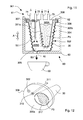
- FIG. 11 is a schematic cross section of another embodiment of the capsule of the invention provided with an internal filtering element and inserted into the dispensing machine, in a first operating step of injecting a pressurised fluid;
- FIG. 12 is a perspective view of the supporting element and of the filtering element of the capsule in FIG. 11 ;
- FIG. 13 is a schematic cross section of a further version of the capsule in FIG. 11 inserted into the dispensing machine and in a first operating step of injecting a pressurised fluid;
- FIG. 14 is a perspective view of the supporting element and of the filtering element of the capsule in FIG. 13 ;
- FIG. 15 is a schematic view of the dispensing machine.
- the capsule 1 according to the invention is illustrated that is usable in a dispensing machine 60 , disclosed below, for producing, by injecting a pressurised fluid inside the capsule, a final food product, for example a beverage such as coffee, barley, herbal tea, tea, chocolate, etc, or a fluid food such as soup, broth, liquidised vegetables, homogenised foods, etc.
- a final food product for example a beverage such as coffee, barley, herbal tea, tea, chocolate, etc, or a fluid food such as soup, broth, liquidised vegetables, homogenised foods, etc.
- the capsule 1 of the invention in fact comprises an external casing 2 , or container, substantially in the shape of a glass or cup, provided with a base wall 3 and with a first side wall 4 defining a cavity 5 that is open and suitable for containing an initial product P 1 from which to obtain a final food product B 1 .
- the initial product P 1 is a product which is percolable, or soluble, or an infusion product, or freezed-dried or dehydrated.
- the capsule of the invention is further suitable for containing an initial product to be combined with a fluid to make a final product which may also not be a food product, for example a pharmaceutical or phytosanitary product, a cosmetic or a detergent or generally a chemical product.
- final product will refer, by way of non-limiting example, to a beverage.
- the casing 2 is compressible and crushable, made by forming a thermoformable sheet material, in particular a multilayered material made of plastics that is impermeable to liquids and to gases and is suitable for contact with the foodstuffs.
- the capsule 1 further comprises a supporting element 6 fixed to a first edge 7 of the casing 2 and facing the cavity 5 .
- a nozzle 11 is fixed that is arranged for delivering into the cavity 5 a fluid L, in particular a hot pressurised liquid, for example water or milk, which interacts with the initial product P 1 to make the beverage B 1 , in a first preparatory operating step F 1 of the latter.
- the nozzle 11 is further set up to open, in particular perforate, the base wall 3 of the casing 2 and to enable the beverage B 1 to exit the capsule 1 , in a second operating step F 2 in which the aforesaid casing is progressively compressed and/or crushed to reduce a volume of said casing, and thus of said capsule (in particular by moving the base wall 2 towards the supporting element 6 or the first edge 7 ), and making the beverage exit.
- the nozzle 11 comprises a stiff tubular element, made for example of plastics, provided with a pointed end 11 b that is able to perforate the base wall 3 .
- the base wall 3 comprises an opening promoting device 9 , 10 arranged for interacting and cooperating with the nozzle 11 to make the opening for the beverage B 1 to exit.
- the opening promoting device comprises an exit hole 9 closed hermetically by a closing element 10 that is fixed outside the base wall 3 and is perforable or detachable by the nozzle 11 .
- the closing element 10 comprises, for example, a label made of aluminium or plastics fixed, in particular glued, to the base wall 3 .
- the closing element 10 can include an elongated flap that is intended to be locked by a compression device of the dispensing machine 60 , in such a manner as to prevent the aforesaid closing element 10 from being completely detached and falling into a consumption receptacle underneath, during opening of the capsule 1 and dispensing of the beverage ( FIG. 7 ).
- the opening promoting device comprises a pre-incision line 15 or a weakening portion made on the base wall 3 that facilitates perforation of the latter by the nozzle 11 .
- the weakening portion can comprise a portion with a reduced or thinned thickness of said base wall 3 that is perforable by the nozzle 11 .
- the capsule 1 after being opened, is further compressed and/or crushed in such a manner as to further reduce the volume thereof—in particular by moving the base wall 2 towards the supporting element 6 or the first edge 7 —and enabling the beverage B 1 to exit completely, in particular if the latter is dense and/or viscous. Crushing the capsule 1 in fact progressively reduces the volume also of the cavity 5 from which the beverage B 1 is forced to exit.
- Compressing and crushing the capsule 1 in the second operating step F 2 can facilitate and cooperate with the nozzle 11 to open the capsule 1 .
- the closing element 10 and/or the pre-incision line 15 of the base wall 3 are dimensioned and configured such that the opening (i.e. the detachment of the closing element 10 or the breakage of the wall portion at the pre-incision line 15 ) occurs only by virtue of the internal pressure of the beverage caused by the nozzle 11 compressing without perforating.
- the side wall 4 is deformable and/or compressible, in particular it has an accordion-shape or bellows-shape. Further, the side wall 4 is divergent from the base wall 3 to the first edge 7 , for example it has a frustoconical shape.
- a covering element 8 is fixed to the first edge 7 of the casing 2 and/or to an external face 6 a of the supporting element 6 for hermetically closing the capsule 1 .
- the first edge 7 forms an annular seat 7 a that receives a peripheral edge 6 c of the supporting element 6 that can be fixed there by welding or gluing, or by assembly through interference.
- the capsule 1 is further provided with one or more further nozzles 12 , 13 , for example two, which are substantially identical to one another, which are also fixed to the supporting element 6 and arranged for delivering the fluid L into the cavity 5 in the first step F 1 .
- the further nozzles 12 , 13 are arranged substantially parallel to the nozzle 11 and alongside on opposite sides of the latter in such a manner as to move respective end portions 12 b , 13 b towards the side wall 4 .
- the further nozzles 12 , 13 have a greater length than the nozzle 11 , such as to have the respective end portions 12 b , 13 b inserted inside the initial product P 1 and substantially in contact with the base wall 3 .
- each further nozzle 12 , 13 is shaped in such a manner as to direct respective jets of fluid L towards the side wall 4 , in particular in a substantially tangential direction, in such a manner as to create a vortical flow or vortex 16 of fluid L and initial product P 1 , which are progressively mixed, which vortex 16 rises from the base wall 3 to the supporting element 6 ( FIG. 5 ).
- each further nozzle 12 , 13 comprises at the respective end portion 12 b , 13 b at least one injection opening 12 c , 13 c , having, for example, a cutting or longitudinal slot shape.
- the nozzle 11 is on the other hand configured for directing at least one jet of fluid L downwards, i.e. in the direction of the base wall 3 and substantially to the centre of the vortical flow 16 in order to push the still dry initial product P 1 towards the base wall 3 and to maintain the initial product P 1 on the base wall 3 .
- the tests run have shown that as the further nozzles 12 , 13 are partially inserted into the initial product P 1 in an initial dispensing step, the jets of fluid L dispensed thereby tend to raise the upper portion of initial product P 1 that is still dry, making the upper portion adhere to an internal face 6 b of the supporting element 6 and/or to portions of the side wall 4 that are adjacent to the first edge 7 .
- the pressure and flow of the fluid dispensed by the nozzle 11 can be different, in particular greater, than the pressure and the flow rate of fluid dispensed by the further nozzles 12 , 13 .
- the nozzle 11 comprises at least one respective delivery opening made on, or near, the pointed and shaped end 11 b to direct a respective jet of fluid L downwards in the direction of the base wall 3 and the centre of the vortical flow 16 .
- the nozzle 11 comprises a central delivery opening leading onto the aforesaid pointed end 11 b and a plurality of further delivery openings that are made on a side wall of said nozzle and are adjacent to said pointed end 11 b.
- the nozzle 11 comprises a plurality of delivery openings, made on a side wall of the nozzle near the supporting element 6 , i.e. spaced away from the base wall 3 .
- Such delivery openings are angularly spaced apart from one another substantially orthogonally to a longitudinal axis of the nozzle 11 or tilted downwards, for example by an angle of 45°, in such a manner as to direct a plurality of jets of fluid L to the base wall 3 and to the centre of the vortical flow 16 to push the still dry initial product P 1 to the base wall 3 and to maintain the still dry initial product P 1 thereupon.
- the combination of the jets of fluid L dispensed by the nozzle 11 and by the further nozzles 12 enables products to be solubilised and dissolved completely and homogenously without the manual intervention of a user that are difficult to dissolve or slowly soluble and/or contain thickeners and stabilisers, or freezed-dried or dehydrated products, such as to obtain dense or viscous final products (for example beverages such as liquid chocolate) perfectly dissolved and devoid of coagulated matter and lumps.
- the pressure and temperature of the injected fluid have to be suitably adjusted in function of the type and composition of the initial product.
- the temperature of the fluid i.e. of the water
- the temperature range to use varies between 55° C. and 80° C., in particular between 60° C. and 70° C.
- the injection pressure of the water through the nozzle 11 is comprised between 1.5 and 6 bar, in particular between 3.5 and 4.5 bar.
- the injection pressure of the water through the further nozzles 12 , 13 is comprised between 1 and 4 bar, in particular between 2 and 3 bar.
- the quantity of water dispensed by the nozzle 11 is equal to that dispensed by both the further nozzles 12 , 13 (for example a total of 100 ml for 30-35 g of powder of initial product).
- the cavity 5 of the capsule 1 must be filled with the necessary quantity or volume of fluid L, which is, for example, suitable for making a dose of beverage, before the opening of the base wall 3 and dispensing.
- the beverages exit from the capsule 1 by means of progressive compressing and crushing of the casing 1 in the second operating step F 2 .
- each further nozzle 12 , 13 is deformable and/or compressible.
- each further nozzle 12 , 13 comprises a corrugated or bellows-shaped tubular wall that can be easily compressed and/or folded and deformed, as illustrated in FIG. 8 .
- the nozzle 11 has a length that is calculated in function of the volume occupied at the end of the first operating step F 1 by the mixed and solubilised beverage B 1 , before the bottom wall 3 is opened (in FIG. 7 reference 18 indicates the level reached by the beverage B 1 after the fluid L has been introduced).
- the length of the nozzle 11 is such as to perforate the bottom wall 3 before the residual volume of the cavity 5 , with the partially crushed capsule 1 is lower than the volume of the beverage B 1 , to avoid the beverage B 1 being able to exit the capsule, for example by rising up from the nozzles 11 , 12 , 13 or from a vent provided on the supporting element 6 .
- the supporting element 6 comprises a body having a substantially flat shape, for example a disc, and provided with one or more openings 17 , 18 , for example two, to introduce the initial product P 1 into the cavity 5 of the capsule 1 in a filling step of the latter.
- the nozzle 11 is fixed to an internal face 6 b of the supporting element 6 , whereas on an opposite external face 6 a of the latter a supplying hole 19 is provided that is flowingly connected to an internal conduit 11 a of said nozzle 11 .
- the further nozzles 12 , 13 are fixed to the internal face 6 b , on the opposite external face 6 a respective further supplying holes 20 , 21 being provided that are flowingly connected to further internal conduits 12 a , 13 a of the respective further nozzles 12 , 13 .
- a vent hole 22 can be provided on the supporting element 6 to permit the necessary venting during the operating step F 1 of the air contained in the capsule 1 that is sealed together with the initial product P.
- the supporting element 6 and the nozzles 11 , 12 , 13 can be made as a single body, for example by injection moulding of plastics.
- the supplying holes 19 , 20 , 21 of the supporting element 6 are arranged for engaging with an injecting device 61 of a dispensing machine 60 ( FIG. 7 ).
- the injecting device 61 comprises a plurality of needles 71 , 72 , 73 or similar elements arranged for perforating the covering element 8 and being inserted and sealingly abutting on the respective supplying holes 19 , 20 , 21 , such as to deliver fluid L into the cavity 5 through the nozzles 11 , 12 , 13 .
- the injecting device 61 comprises a needle 71 that is inserted into the supplying hole 19 to inject the fluid L into the nozzle 11 and further needles 72 , 73 , in a number that is the same as the number of further nozzles 12 , 13 that are inserted into the respective further supplying holes 20 , 21 to inject the fluid L into the aforesaid further nozzles 12 , 13 .
- the injecting device 61 can also include a further needle 74 arranged for perforating the covering element 8 and being inserted and sealingly abutting on the vent hole 22 of the supporting element 6 in such a manner as to enable the air to exit the capsule 1 .
- the injecting device 61 of the dispensing machine 60 does not come into contact with the initial product P 1 and/or with the mixture/beverage during the preparation step and subsequently during the dispensing step.
- a supply circuit of the machine that includes the injecting device 61 is not dirtied or tainted with the initial product and/or the beverage, this ensuring the hygiene of the dispensing process and the quality of the beverages at each dispensing, preserving the organoelptic properties thereof.
- the capsule 1 for beverages of the invention can be used on a dispensing machine 60 that is devoid of a dispensing circuit because this capsule does not require an extracting device that is suitable for perforating the bottom thereof to enable the beverage to exit, nor a conduit for conveying the beverage to the consumption receptacle (for example a cup, an espresso cup, a glass, etc).
- FIG. 6 illustrates schematically one version of the capsule 101 of the invention that differs from the embodiment that is disclosed above and shown in FIGS. 1 to 5 , by the casing 102 that has a side wall 104 that is convex to the outside, i.e. divergent from the base wall 3 and thus again convergent until the first edge 107 .
- casing 102 With this form of casing 102 , it is possible to create with the nozzle 11 and the further nozzles 12 , 13 a vortical flow or a vortex 16 of fluid and initial product, that are progressively mixed, that from the base wall 103 rises up towards the supporting element 6 and a further vortical flow 16 ′ of fluid and initial product that from the supporting element 6 descends to the base wall 103 .
- the double vortical flow 16 , 16 ′ permits more efficient and rapid mixing and solubilisation of the initial product.
- the closing element is devoid of an extended flap.
- FIG. 9 there is illustrated another embodiment of the capsule 201 of the invention that is particularly suitable for making a beverage from an initial product P 2 that solubilises easily and rapidly, for example soluble tea or coffee.
- This capsule 201 embodiment differs from the embodiment that is illustrated above and shown in FIGS. 1 to 5 by the fact that it comprises a single nozzle 211 fixed to the supporting element 206 . Further, the casing 202 is lower in height as in this case it is not necessary for the cavity 205 to be filled with the volume or quantity of liquid L necessary for making a dose of beverage, before the base wall 203 is opened. In fact, by virtue of the high solubility of the initial product P 2 , dispensing into the consumption receptacle 50 can take place at the same time as delivery of fluid L into the capsule 201 . More precisely, in a first step F 1 , fluid L is delivered into the capsule 201 in a reduced quantity, but such as to dissolve the initial product P 2 completely.
- the capsule 201 is compressed and crushed (by a compressing device 62 of the dispensing machine 60 ) in the direction A, reducing the volume of the cavity 5 and enabling the nozzle 211 to perforate the base wall 203 for the exit of a beverage B 2 that is very concentrated but devoid of lumps or coagulated matter.
- fluid L is delivered that finishes partly inside the capsule and partially directly in the consumption receptacle 50 .
- the supporting element 206 comprises a body having a substantially flat shape, for example a disc, and being provided with one or more openings 217 , 218 , for example two, for introducing the initial product P 2 into the cavity 205 of the capsule 201 in a filling step of the latter.
- the nozzle 211 is fixed to an internal face 206 b of the supporting element 6 , whilst on an opposite external face 206 a of the latter a supplying hole 219 is provided that is flowingly connected to an internal conduit 211 a of the nozzle 11 .
- the supplying hole is arranged for engaging with a needle 71 of the injecting device 261 of the dispensing machine 60 .
- Blind holes 220 , 221 are further provided on the external face 206 a to abut on and close the further needles 72 , 73 of the injecting device 61 of the dispensing machine 60 , since in this case the capsule 201 is devoid of further nozzles to be supplied.
- a vent hole 222 is provided on the supporting element 206 to permit the necessary venting during the operating step F 1 of the air contained in the capsule 1 that is sealed together with the initial product P 2 .
- the vent hole 222 is arranged for engaging with another further needle 74 of the injecting arrangement 61 .
- the nozzle 311 is positioned on the supporting element 306 in such a manner as to deliver the fluid L to a second chamber 305 B defined between the casing 302 and the filtering element 30 .
- the nozzle 311 is engaged by a further needle 72 of the injecting device 61 of the dispensing machine 60 .
- the fluid L filters through the permeable walls of the filtering element 30 in the initial product P 3 .
- the quantity of fluid L delivered, via the nozzle 311 into the capsule 301 by the injecting device 61 of the dispensing machine 60 is approximately what is required to make a dose of beverage.
- the covering element 208 is fixed to the first edge 207 of the casing 202 and to the external face 206 a of the supporting element 206 for hermetically closing the capsule 201 .
- FIGS. 11 and 12 illustrate another embodiment of the capsule 301 for beverages of the invention that differs from the capsule 1 disclosed above and represented in FIGS. 1 to 5 , by the fact that it comprises a single nozzle 311 and a filtering element 30 , both fixed to the supporting element 306 .
- the nozzle 311 is made as a single body with the supporting element 306 , for example by injection moulding of plastics.
- the filtering element 30 has the shape of a bag and extends from the supporting element 306 to the cavity 305 defining a first chamber 305 A therein containing an initial product P 3 , typically an infusion product, for example coffee, tea, herbal tea, etc.
- the filtering element 30 is made of material that is permeable to liquids and light and soft, typically filter paper made of cellulose or polymeric material.
- the filtering element 30 is provided with a side wall comprising a plurality of longitudinal pleats or folds that are able to increase the filtering surface thereof.
- the capsule 301 is compressed and crushed (by a compressing device 62 of the dispensing machine 60 ) in the direction A, reducing the volume thereof and enabling the nozzle 311 to perforate the base wall 303 to enable the beverage B 3 to exit.
- the needle 71 and/or the remaining further needle 73 of the injecting arrangement 61 of the dispensing machine 60 can perforate the covering element 308 of the capsule 301 and, before the further needle 72 injects the fluid L via the nozzle 311 , can inject water vapour directly onto the initial product P 3 , typically to prepare the initial product P 3 for subsequent percolation (if the initial product is tea leaf the vapour is used to distend the latter).
- an intermediate infusion step follows (in which the dispensing machine 60 is on standby) that is of a duration that is such as to enable the beverage B 3 to be made by infusion of the initial product P 3 .
- the duration of this step depends on the type and on the properties of the aforesaid initial product P 3 (typically from 1 to 5 minutes).
- the nozzle 311 is fixed to an internal face 306 b of the supporting element 6 , whereas on an opposite external face 306 a of the latter a supplying hole 319 is provided that is flowingly connected to an internal conduit 311 a of the nozzle 11 .
- the supplying hole 319 is arranged for engaging with a further needle 72 of the injecting device 61 of the dispensing machine 60 .
- the needle 71 and the remaining needle 73 of the injecting device 61 can be configured in such a manner as to perforate the covering element 308 and be inserted partially into the opening 317 .
- a vent hole 322 is provided on the supporting element 306 to permit the necessary venting during the operating step F 1 of the air contained in the capsule 1 that is sealed together with the initial product P 3 .
- the vent hole 322 is arranged for engaging with another further needle 74 of the injecting device 61 .
- the supporting element 306 comprises a body having a substantially flat shape, for example a disc, and provided with an opening 317 on an edge of which an open end of the filtering element 30 is fixed.
- the opening 317 further enables the initial product P 3 to be introduced into the filtering element 30 .
- the nozzle 411 is used in the second crushing step F 2 of the capsule 401 (by the compressing device 62 of the dispensing machine 60 ) in the direction A to perforate the base wall 403 and to enable the beverage B 4 to exit into the consumption receptacle 50 .
- capsule 401 a with filtering element that differs from the embodiment disclosed above by the fact that it comprises a nozzle 411 and a further nozzle 412 that are fixed to the supporting element 406 .
- This version of capsule 401 is particularly suitable for obtaining a beverage B 4 from an initial product P 4 contained in the filtering element 30 by percolation.
- the fluid L is introduced into the first step F 1 via the further nozzle 412 , such that it can percolate through the initial product P 4 and the beverage thus obtained can filter through the permeable walls of the filtering element 30 into the second chamber 405 of the cavity 404 .
- the volume or quantity of fluid delivered, via the nozzle 412 into the capsule by the injecting device 61 of the dispensing machine 60 is approximately what is necessary to make a dose or serving of beverage.
- the nozzle 411 can be optionally used in the first operating step F 1 also to deliver fluid L into the cavity 405 .
- an intermediate percolation step can follow (in which the dispensing machine 60 is on standby) that is of a duration that is such as to enable percolation of the fluid L through the initial product P 4 to obtain the beverage B 4 .
- the duration of this step depends on the type and properties of the aforesaid initial product P 4 .
- the nozzle 411 and the further nozzle 412 are fixed to the internal face 406 b of the supporting element 6 .
- a supplying hole 419 is provided that is flowingly connected to an internal conduit 411 a of the nozzle 11 and a further supplying hole 420 is provided that is flowingly connected to a respective internal conduit 412 a of the further nozzle 412 .
- the further supplying hole 420 is arranged for engaging with a needle 71 of the injecting device 61 of the dispensing machine 60
- the supplying hole 420 is arranged for engaging with a further needle 72 of the injecting device 61 .
- a blind hole 421 is provided on the external face 406 a for abutting on and closing a remaining further needle 73 of the injecting device 61 .
- a vent hole 422 is provided on the supporting element 406 to permit the necessary venting during the operating step F 1 of the air contained in the capsule 401 that is sealed together with the initial product P 4 .
- the vent hole 422 is arranged for engaging with another further needle 74 of the injecting device 61 .
- the nozzle 411 and/or the further nozzle 412 can continue delivering the fluid L to obtain further beverage B 4 to be dispensed into the consumption receptacle 50 .
- the supporting element 406 comprises a body that has a substantially flat shape, for example a disc shape, and is provided with one or more openings 417 , 418 , for example two, for introducing the initial product P 4 into the filtering element 30 .
- a peripheral end edge thereof is fixed to the internal face 406 b of the supporting element 6 , at the two openings 417 , 418 .
- the dispensing machine 60 arranged in particular for using the capsule for beverages disclosed above, comprises a positioning device 63 suitable for receiving and containing a capsule 1 , 201 , 301 , 401 and is movable in both directions along the direction A, which is substantially vertical and orthogonal to the base wall of the capsule.
- the positioning device 63 can receive capsules of different dimensions, for example the capsule 1 for products that are difficult to dissolve and/or dense of FIGS. 1 and 7 or the capsule 201 for easily soluble products in FIG. 9 .
- the positioning arrangement 63 is movable to an intermediate operating position S 2 in which the upper part of the capsule 1 provided with covering element 8 abuts on an abutting element 62 and an injecting device 61 of the dispensing machine 60 .
- the positioning device is further movable along the direction A, upwards, to a final operating position S 3 for progressively compressing and crushing the capsule 1 against the abutting element 62 and the injecting device 61 of the dispensing machine 60 in such a manner as to reduce the volume of the capsule, and thus of the cavity 5 , and enable the cavity 5 to open and the beverage to exit.
- the positioning device 63 is driven by a movement device 64 , of known type and illustrated schematically in FIG. 15 , controlled by a control unit 80 of the dispensing machine 60 , with the methods disclosed below.
- the injecting device 61 includes a plurality of needles or similar elements 71 , 72 , 73 arranged for perforating the covering element 8 of the capsule 6 and being inserted and sealingly abutting on respective supplying holes 19 , 20 , 21 provided on the supporting element 6 underneath so as to deliver the fluid L into the cavity 5 through the nozzles 11 , 12 , 13 .
- the injecting device 61 comprises a needle 71 and one or more further needles 72 , 73 , for example two.
- the injecting device 61 further includes another needle 74 arranged for perforating the covering element 8 and being inserted and sealingly abutting on a vent hole 22 of the supporting element 6 in such a manner as to enable the air to exit the capsule 1 .
- the injecting device 61 is connected by respective conduits 75 and a valve element 76 to a manifold 77 supplied by a pump 66 with the pressurised fluid L, typically water or milk.
- the pump 66 is, for example, a volumetric piston pump with an adjustable stroke controlled by the control unit 80 that enables the pressure, the flow rate and the quantity of fluid L to be dispensed at each cycle into the capsule to be regulated with precision.
- the aforementioned parameters that depend on the type of capsule used in the machine 60 and on the initial product contained therein are stored in the control unit 80 of the dispensing machine 60 .
- the valve element 76 enables the passage and delivery pressure of the fluid to each of the needles of the injecting device 61 to be controlled.
- a further pump is provided that supplies a further manifold to which the further nozzles 12 , are connected.
- the pump and the further pump can respectively supply the nozzle 11 and the further nozzles 12 , 13 with different fluid pressures and flow rates, in function of the type of capsule used.
- the pump 66 draws the high-temperature fluid L from a boiler 67 , which is also controlled by the control unit 80 to heat/maintain the fluid L at a desired consumption temperature.
- a tank 68 supplies the boiler 67 continuously.
- the boiler 67 is further set up for supplying, via a further conduit 79 , the manifold 77 directly and thus the injecting device 61 to inject into the capsule 1 the fluid in the form of steam.
- Further valve element 78 intercepts and regulates the flow of steam from the boiler 67 to the manifold 77 .
- the abutting element 62 substantially includes an annular plate that acts on the edge 7 of the casing 2 and on a peripheral portion of the supporting element 6 .
- the plate 62 is fixed to a frame of the dispensing machine or to the injecting device 61 .
- the dispensing machine 60 further includes an interface 81 having, for example, a control panel by means of which the user not only switches the machine on and off by means of the “start” and “stop” buttons but may also select the type of capsule inserted into the machine, for example a capsule 1 having a first size (or height) and containing an initial product P 1 that is difficult to dissolve to make a dense beverage (chocolate) (first type H 1 ), a capsule 201 having a second size and containing an initial product P 2 that is easily soluble (for example a herbal tea) (second type H 2 ), a capsule 301 of a third size (which may coincide with the first size) containing a filtering element 30 and an initial product P 3 for infusion (for example tea) (third type H 3 ), a capsule 401 of a fourth size (which may coincide with the first size or with the third size) containing a filtering element 30 and an initial product P 4 for percolation (for example coffee) (fourth type H 4 ), etc.
- Operating parameters of the dispensing machine 60 are associated with each type H 1 , H 2 , H 3 , H 4 of capsule that are set and stored in the control unit 80 and permit automatic operation.
- the positioning device 63 is moved by a movement device 64 from the initial operating position S 1 to a respective intermediate operating position S 2 in which the upper part of the capsule abuts on the abutting element 62 and the injecting device 61 , the latter perforating the covering element 8 and abutting on the supplying holes (and/or the blind holes).
- control unit 80 also regulates the temperature of the fluid L exiting the boiler 67 , the delivery pressure of the pump 66 and/or the dispensing pressure from the nozzle 11 and from the further nozzles, the quantity of hot and pressurised fluid L to be sent and the needle or the needles of the injecting device 61 to which to send the aforementioned fluid L (via the valve element 77 ).
- the control unit 80 establishes the duration of the operating steps F 1 , F 2 and the duration of an intermediate infusion or percolation step of the initial product.
- the control unit 80 commands the movement device 64 that drives the positioning device 63 in the direction A from the intermediate operating position S 2 to the final operating position S 3 for progressively compressing and crushing the capsule 1 , reducing the volume thereof, in order to open the capsule 1 and release the beverage obtained in the consumption receptacle 50 .
- the capsule 1 has a reduced volume (final volume), compared with an initial volume, having been progressively compressed and crushed by the positioning device 63 against the injecting device 61 .
- control unit 80 can further set dispensing the fluid L from the nozzle 11 also during the second operating step F 2 , in particular directly into the consumption receptacle 50 to dilute the beverage until the beverage is brought up to the desired concentration.
Landscapes
- Engineering & Computer Science (AREA)
- Food Science & Technology (AREA)
- Mechanical Engineering (AREA)
- Apparatus For Making Beverages (AREA)
- General Preparation And Processing Of Foods (AREA)
- Devices That Are Associated With Refrigeration Equipment (AREA)
- Medical Preparation Storing Or Oral Administration Devices (AREA)
Applications Claiming Priority (13)
| Application Number | Priority Date | Filing Date | Title |
|---|---|---|---|
| ITBO2011A000042A IT1403544B1 (it) | 2011-01-31 | 2011-01-31 | Capsula per bevande |
| ITBO2011A000041A IT1403543B1 (it) | 2011-01-31 | 2011-01-31 | Capsula per bevande |
| ITBO2011A000040A IT1403542B1 (it) | 2011-01-31 | 2011-01-31 | Capsula per bevande |
| ITBO2011A000039 | 2011-01-31 | ||
| ITBO2011A000040 | 2011-01-31 | ||
| ITBO2011A0039 | 2011-01-31 | ||
| ITBO2011A000042 | 2011-01-31 | ||
| ITBO2011A0040 | 2011-01-31 | ||
| ITBO2011A0042 | 2011-01-31 | ||
| ITBO2011A000041 | 2011-01-31 | ||
| ITBO2011A0041 | 2011-01-31 | ||
| ITBO2011A000039A IT1403541B1 (it) | 2011-01-31 | 2011-01-31 | Macchina erogatrice per bevande |
| PCT/IB2012/050391 WO2012104760A1 (en) | 2011-01-31 | 2012-01-27 | Capsules and dispensing machine |
Publications (2)
| Publication Number | Publication Date |
|---|---|
| US20140026761A1 US20140026761A1 (en) | 2014-01-30 |
| US10011421B2 true US10011421B2 (en) | 2018-07-03 |
Family
ID=45833478
Family Applications (1)
| Application Number | Title | Priority Date | Filing Date |
|---|---|---|---|
| US13/982,897 Active 2035-10-02 US10011421B2 (en) | 2011-01-31 | 2012-01-27 | Capsules and dispensing machine |
Country Status (8)
| Country | Link |
|---|---|
| US (1) | US10011421B2 (de) |
| EP (2) | EP3100963B1 (de) |
| JP (1) | JP5917570B2 (de) |
| CN (1) | CN103476687B (de) |
| CA (1) | CA2825999C (de) |
| ES (2) | ES2723482T3 (de) |
| IT (1) | IT1403541B1 (de) |
| WO (1) | WO2012104760A1 (de) |
Cited By (12)
| Publication number | Priority date | Publication date | Assignee | Title |
|---|---|---|---|---|
| WO2020092472A3 (en) * | 2018-10-30 | 2020-07-23 | Keurig Green Mountain, Inc. | Beverage preparation machine with inlet arrangement |
| US10737876B2 (en) | 2015-07-13 | 2020-08-11 | K-Fee System Gmbh | Filter element having a cut-out |
| USD898169S1 (en) | 2018-10-30 | 2020-10-06 | Keurig Green Mountain, Inc. | Gasket arrangement |
| USD908426S1 (en) | 2019-02-21 | 2021-01-26 | Keurig Green Mountain, Inc. | Needle arrangement |
| USD908850S1 (en) | 2018-10-30 | 2021-01-26 | Keurig Green Mountain, Inc. | Gasket arrangement |
| US11045035B2 (en) | 2015-09-18 | 2021-06-29 | K-Fee System Gmbh | Adapter for a single serve capsule |
| USD925281S1 (en) | 2019-12-04 | 2021-07-20 | Keurig Green Mountain, Inc. | Needle arrangement |
| US11084650B2 (en) | 2015-06-10 | 2021-08-10 | K-Fee System Gmbh | Portion capsule with a three-ply nonwoven fabric |
| US20220061580A1 (en) * | 2018-12-12 | 2022-03-03 | Koninklijke Douwe Egberts B.V. | Air purge groove |
| USD969547S1 (en) | 2020-04-16 | 2022-11-15 | Sarong Societa' Per Azioni | Coffee capsule |
| US12227323B2 (en) | 2018-07-27 | 2025-02-18 | Gcs German Capsule Solution Gmbh | Method for producing a portion capsule |
| US12459728B2 (en) | 2018-11-22 | 2025-11-04 | Gcs German Capsule Solution Gmbh | Seal for a single serve capsule |
Families Citing this family (78)
| Publication number | Priority date | Publication date | Assignee | Title |
|---|---|---|---|---|
| US10722066B2 (en) * | 2010-12-04 | 2020-07-28 | Adrian Rivera | Windowed single serving brewing material holder |
| US11832755B2 (en) * | 2007-07-13 | 2023-12-05 | Adrian Rivera | Brewing material container for a beverage brewer |
| PT2778098T (pt) * | 2009-06-17 | 2019-01-11 | Douwe Egberts Bv | Sistema e método para preparação de uma quantidade predeterminada de bebida |
| DE102010044945A1 (de) | 2010-05-28 | 2011-12-01 | Eugster/Frismag Ag | Brühvorrichtung zum Extrahieren einer Portionskapsel, Verfahren zum Betrieb einer Brühvorrichtung, Verfahren zur Herstellung einer Brühvorrichtung und Verwendung einer Brühvorrichtung |
| US10071851B2 (en) | 2010-07-12 | 2018-09-11 | Robert Bao Vu | Apparatus and products for producing beverages, and methods for making and using same |
| DK3521210T3 (da) | 2010-07-22 | 2020-04-14 | K Fee System Gmbh | Portionskapsel med stregkode |
| ITBO20120104A1 (it) * | 2012-03-05 | 2013-09-06 | Macchiavelli Srl | Capsula intercambiabile per la preparazione di una infusione di un prodotto in polvere, e relativo procedimento per l'ottenimento di una tale infusione |
| US9345360B2 (en) * | 2012-05-04 | 2016-05-24 | Brian Sims | Method of making infant formula and related devices |
| DE102012105282A1 (de) | 2012-06-18 | 2013-12-19 | K-Fee System Gmbh | Portionskapsel und Verfahren zur Herstellung eines Getränks mit einer Portionskapsel |
| WO2014037299A2 (en) * | 2012-09-05 | 2014-03-13 | Nestec S.A. | A food preparation machine with safety feature |
| ES2690564T3 (es) * | 2012-11-09 | 2018-11-21 | Cristiano PAOLINI | Sistema para la distribución de bebidas |
| DE102012223291A1 (de) | 2012-12-14 | 2014-06-18 | K-Fee System Gmbh | Portionskapsel und Verfahren zur Herstellung eines Getränks mit einer Portionskapsel |
| WO2014097203A1 (fr) * | 2012-12-21 | 2014-06-26 | Psr Profitable Strategic Redeployment Sàrl | Capsule pour la preparation d'une boisson |
| ITMO20120327A1 (it) * | 2012-12-27 | 2014-06-28 | Sarong Spa | Capsula per bevande |
| CA2895646A1 (en) * | 2012-12-27 | 2014-07-03 | Sarong Societa' Per Azioni | Capsule for beverages |
| EP3336012A1 (de) * | 2012-12-27 | 2018-06-20 | Sarong Societa' Per Azioni | Kapsel für getränke |
| ITMO20120326A1 (it) * | 2012-12-27 | 2014-06-28 | Sarong Spa | Capsula per bevande |
| ITMO20130296A1 (it) * | 2013-10-17 | 2015-04-18 | Sarong Spa | Capsula per bevande |
| WO2014121838A1 (en) * | 2013-02-07 | 2014-08-14 | Klaus Kroesen | Apparatus for dispensing a beverage |
| DE102013215274A1 (de) * | 2013-02-20 | 2014-08-21 | K-Fee System Gmbh | Portionskapsel und System |
| GB201308927D0 (en) * | 2013-05-17 | 2013-07-03 | Kraft Foods R & D Inc | A beverage preparation system, a capsule and a method for forming a beverage |
| DE202014011505U1 (de) | 2013-05-17 | 2021-06-24 | Koninklijke Douwe Egberts B.V. | Getränkeherstellungssystem |
| CA2909011A1 (en) | 2013-05-28 | 2014-12-04 | Nestec S.A. | A capsule for beverage preparation |
| RU2651261C2 (ru) | 2013-07-10 | 2018-04-18 | Нестек С.А. | Капсула для приготовления напитка |
| ITMO20130295A1 (it) | 2013-10-17 | 2015-04-18 | Sarong Spa | Macchina erogatrice di bevande |
| WO2015089660A1 (en) * | 2013-12-16 | 2015-06-25 | 2266170 Ontario Inc. | Capsule with sensory attributes |
| US10485376B2 (en) * | 2013-12-20 | 2019-11-26 | Koninklijke Philips N.V. | Set of consumables and beverage dispenser |
| US9474406B2 (en) | 2014-01-17 | 2016-10-25 | Keurig Green Mountain, Inc. | Apparatus with beverage cartridge holder having movable outlet |
| EP3107432A1 (de) * | 2014-02-19 | 2016-12-28 | Nestec S.A. | Kapselkit zur verwendung in einer lebensmittelherstellungsmaschine |
| WO2015144730A1 (de) * | 2014-03-24 | 2015-10-01 | K-Fee System Gmbh | Portionskapsel und verfahren zur herstellung eines getränks |
| GB201420262D0 (en) | 2014-11-14 | 2014-12-31 | Kraft Foods R & D Inc | A method of forming a cup-shaped body for a beverage capsule |
| RU2017133486A (ru) | 2015-02-27 | 2019-03-27 | К-Фее Зюстем Гмбх | Порционная капсула с прикрепленным посредством термосварки фильтрующим элементом |
| US9487348B2 (en) | 2015-03-20 | 2016-11-08 | Meltz, LLC | Systems for and methods of providing support for displaceable frozen contents in beverage and food receptacles |
| US10111554B2 (en) | 2015-03-20 | 2018-10-30 | Meltz, LLC | Systems for and methods of controlled liquid food or beverage product creation |
| US10314320B2 (en) | 2015-03-20 | 2019-06-11 | Meltz, LLC | Systems for controlled liquid food or beverage product creation |
| US9346611B1 (en) | 2015-03-20 | 2016-05-24 | Meltz, LLC | Apparatus and processes for creating a consumable liquid food or beverage product from frozen contents |
| ITBO20150179A1 (it) | 2015-04-14 | 2016-10-14 | Ali Group Srl Carpigiani | Macchina per la realizzazione di gelato. |
| EP3139614A1 (de) * | 2015-09-07 | 2017-03-08 | Thomson Licensing | Verfahren und vorrichtung zur codierung und decodierung eines lichtfeldbasierten bildes und zugehöriges computerprogrammprodukt |
| DE102015115250A1 (de) * | 2015-09-10 | 2017-03-16 | Pester Pac Automation Gmbh | Verwendung einer Verpackung |
| ITUB20154199A1 (it) | 2015-10-07 | 2017-04-07 | Carpigiani Group Ali Spa | Macchina e metodo per la realizzazione di prodotti liquidi e semiliquidi del tipo caldo o freddo. |
| ITUB20155038A1 (it) * | 2015-10-22 | 2017-04-22 | Carpigiani Group Ali Spa | Macchina e metodo per la produzione di prodotti liquidi e semiliquidi del settore gelateria. |
| ITUB20155198A1 (it) | 2015-10-22 | 2017-04-22 | Sarong Spa | Capsula per bevande |
| GB2544722A (en) * | 2015-10-22 | 2017-05-31 | Sabmiller Plc | Dispenser, flavouring container and flavouring method |
| ITUB20155389A1 (it) * | 2015-11-09 | 2017-05-09 | Sarong Spa | Capsula per bevande |
| EP3405412B1 (de) * | 2016-01-18 | 2022-06-15 | Société des Produits Nestlé S.A. | Pack, maschine und system zur zubereitung von lebensmittel- und getränkeprodukten |
| EP3414185B1 (de) * | 2016-02-11 | 2019-11-06 | Société des Produits Nestlé S.A. | Pack, zubereitungsmachine, system und verfahren zur zubereitung von lebensmittel- oder getränkeprodukten, sowie verwendung eines packs |
| USD800497S1 (en) | 2016-02-26 | 2017-10-24 | Bartesian Inc. | Beverage capsule |
| USD812952S1 (en) | 2016-02-26 | 2018-03-20 | Bartesian Inc. | Beverage machine |
| USD843765S1 (en) | 2016-02-26 | 2019-03-26 | Bartesian Inc. | Beverage machine |
| CN111166174B (zh) * | 2016-03-01 | 2022-12-16 | 贝塔什股份有限公司 | 饮料机和与饮料机一起使用的胶囊 |
| IT201600074471A1 (it) | 2016-07-15 | 2018-01-15 | Ali Group Srl Carpigiani | Macchina e metodo per la produzione di prodotti liquidi e semiliquidi del settore gelateria, pasticceria o ristorazione. |
| US20190382191A1 (en) * | 2018-06-19 | 2019-12-19 | Anthony J. Orler | Reconstituted pulp packaging |
| IT201600100869A1 (it) | 2016-10-07 | 2018-04-07 | Ali Group Srl Carpigiani | Metodo e sistema di pulizia di una macchina per la realizzazione di prodotti alimentari liquidi e/o semiliquidi del settore gelateria, pasticceria o ristorazione |
| WO2018136221A2 (en) * | 2016-12-30 | 2018-07-26 | Whirlpool Corporation | Single-serving self-piercing pod for liquid and powdered and granular beverage concentrates |
| IT201700043975A1 (it) | 2017-04-21 | 2018-10-21 | Ali Group Srl Carpigiani | Macchina e metodo per la produzione di prodotti liquidi e semiliquidi del settore gelateria. |
| CA3061607A1 (en) | 2017-04-27 | 2018-11-01 | Meltz, LLC | Method for centrifugal extraction and apparatus suitable for carrying out this method |
| IT201700073146A1 (it) * | 2017-06-29 | 2018-12-29 | Rdl S R L | Capsula monodose per prodotti in polvere o semiliquidi |
| CO2017007101A1 (es) * | 2017-07-14 | 2019-03-08 | Camacho Juan Carlos Gonzalez | Cápsula para bebidas |
| CN108209581A (zh) * | 2018-02-26 | 2018-06-29 | 无锡鼎加弘思饮品科技有限公司 | 可加快溶解的饮品胶囊结构及运行方法 |
| EP3536637B1 (de) | 2018-03-05 | 2020-09-16 | Nootrie AG | Kapsel zur herstellung eines getränks |
| US10881582B2 (en) | 2018-06-11 | 2021-01-05 | Glaxosmithkline Consumer Healthcare Holdings (Us) Llc | Individual dose pack |
| USD890569S1 (en) | 2018-06-19 | 2020-07-21 | Bartesian Inc. | Beverage capsule receiving adaptor |
| US11419791B2 (en) | 2018-07-05 | 2022-08-23 | Fresenius Medical Care Holdings, Inc. | Flexible container systems and nozzles, and related methods |
| USD893293S1 (en) | 2018-08-24 | 2020-08-18 | Bartesian Inc. | Beverage capsule |
| WO2020044146A1 (en) * | 2018-08-30 | 2020-03-05 | Sarong Societa' Per Azioni | Capsule |
| US10624488B2 (en) * | 2018-09-05 | 2020-04-21 | Lify Company Limited | System and method for the preparation of beverages |
| IT201900005912A1 (it) * | 2019-04-16 | 2020-10-16 | Pastificio Rana Spa | Macchina per cuocere una dose di pasta cruda in un contenitore |
| US11724849B2 (en) | 2019-06-07 | 2023-08-15 | Cometeer, Inc. | Packaging and method for single serve beverage product |
| IT201900012390A1 (it) * | 2019-07-19 | 2021-01-19 | Lavazza Luigi Spa | Macchina, sistema e metodo per la preparazione di prodotti alimentari fluidi |
| IT201900012396A1 (it) * | 2019-07-19 | 2021-01-19 | Lavazza Luigi Spa | Contenitore, sistema e metodo per la preparazione di prodotti alimentari fluidi |
| DE102019132205B4 (de) * | 2019-11-27 | 2022-04-07 | Mehmet Bozok | Mischkammer, Getränkekapsel, Getränkeaufbereitungsvorrichtung, Set und Verfahren zur Herstellung eines Getränkes aus einem Konzentrat |
| US11827505B2 (en) * | 2020-02-13 | 2023-11-28 | The Coca-Cola Company | Syringe cartridge assembly for a beverage dispensing system |
| US20210386236A1 (en) * | 2020-06-12 | 2021-12-16 | Nexe Innovations Inc. | Faceplate for improved extraction of beverage material |
| CH717837A9 (de) * | 2020-09-10 | 2022-04-29 | Swiss Tea Innovation Ag | Expandierbarer Aufgussbehälter. |
| CH717836A9 (de) * | 2020-09-10 | 2022-04-29 | Swiss Tea Innovation Ag | Auslassventil für einen Aufgussbehälter und Aufgussbehälter. |
| US11805934B1 (en) * | 2020-10-21 | 2023-11-07 | Adrian Rivera | Brewing material lid and container for a beverage brewer |
| EP4334224A1 (de) * | 2021-05-04 | 2024-03-13 | Société des Produits Nestlé S.A. | Kapsel zur zubereitung eines getränks mit einer getränkeherstellungsvorrichtung |
| US20250127324A1 (en) * | 2021-07-01 | 2025-04-24 | Societe Des Produits Nestle S.A. | Beverage preparation machine and method for preparing a beverage product using such a beverage preparation machine |
Citations (28)
| Publication number | Priority date | Publication date | Assignee | Title |
|---|---|---|---|---|
| US4077551A (en) | 1976-02-13 | 1978-03-07 | Adriana Manaresi | Container with bottom sealing disk which becomes a deformable member on discharge |
| US20020148356A1 (en) | 2001-04-11 | 2002-10-17 | Lazaris Nicholas G. | Beverage filter cartridge holder |
| US20040040983A1 (en) | 2002-09-03 | 2004-03-04 | Ziesel Lawrence B. | Dispensing nozzle |
| US6740345B2 (en) * | 2000-12-22 | 2004-05-25 | Edward Zhihua Cai | Beverage making cartridge |
| US20040115317A1 (en) * | 2001-04-06 | 2004-06-17 | Doglioni Luca Majer | Method for opening sealed containers for foodstuff products |
| US20040112222A1 (en) | 2001-03-31 | 2004-06-17 | Daniel Fischer | Espresso brewing device |
| US20050112262A1 (en) | 2003-11-20 | 2005-05-26 | Jean-Paul In Albon | Means for producing milk drinks or foamed milk drinks |
| AU2005227389A1 (en) | 2004-11-22 | 2006-06-08 | Rene Schifferle | Beverage machine for preparing a hot beverage by brewing and extracting a substance received in a cartridge |
| US20060174769A1 (en) | 2003-07-23 | 2006-08-10 | Eric Favre | Method for preparing a beverage from a capsule and device therefor |
| CN1842290A (zh) | 2003-08-25 | 2006-10-04 | 雀巢技术公司 | 利用容纳物质的胶囊来制备饮料的方法和设备 |
| WO2007114685A1 (en) | 2006-02-17 | 2007-10-11 | Meccano Asia Ltd. | Package and device for preparation of a food product such as a beverage |
| US7335387B2 (en) * | 2001-04-27 | 2008-02-26 | Mars, Inc. | Methods, capsule and apparatuses for the production of foamed drinks |
| WO2009008723A1 (en) | 2007-07-09 | 2009-01-15 | Friesland Brands B.V. | Holder and cup containing concentrate for preparing warm drinks |
| WO2009133134A1 (en) | 2008-04-30 | 2009-11-05 | Nestec S.A. | Sealed capsule for containing beverage ingredients and having an inlet-side membrane |
| CN101594809A (zh) | 2007-01-19 | 2009-12-02 | 雀巢产品技术援助有限公司 | 自主食品和饮料分配机 |
| CN201356446Y (zh) | 2008-12-30 | 2009-12-09 | 薛胜利 | 一种新型胶囊式咖啡机 |
| US20100092629A1 (en) | 2006-11-10 | 2010-04-15 | Beat Keller | Foaming liquid food |
| US20100107889A1 (en) | 2007-03-06 | 2010-05-06 | Nestec S.A. | Device for preparing a liquid beverage from a cartridge |
| WO2010055465A1 (fr) | 2008-11-17 | 2010-05-20 | Tirouvady Moutty | Capsule pour percolation de produit aromatique tel que du café |
| US7798054B2 (en) * | 2004-02-18 | 2010-09-21 | Mds Global Holding Ltd. | Dispensing of a substance |
| WO2010137945A1 (en) | 2009-06-17 | 2010-12-02 | Sara Lee/De N.V. | Capsule and system for preparing a beverage comprising soluble substance |
| US7981451B2 (en) * | 2005-10-14 | 2011-07-19 | Nestec S.A. | Capsule for the preparation of a beverage |
| US20110274802A1 (en) * | 2007-07-13 | 2011-11-10 | Adrian Rivera | Disposable Single Serving Beverage Pod Adapter |
| US8501254B2 (en) * | 2009-06-17 | 2013-08-06 | Koninklijke Douwe Egberts B.V. | System, a method and a capsule for preparing a pre-determined quantity of beverage |
| US8563058B2 (en) * | 2009-03-31 | 2013-10-22 | Nestec S.A. | Capsule with filter for preparing a liquid nutritional or food composition and related beverage production system |
| US20130287891A1 (en) * | 2004-05-26 | 2013-10-31 | Pamela Saha | Disposable combined squeezer/stirrer/dispenser/brewer device |
| US8720320B1 (en) * | 2007-07-13 | 2014-05-13 | ARM Enterprises, Inc. | Pod adaptor system for single service beverage brewers |
| US9572452B2 (en) * | 2010-12-04 | 2017-02-21 | Adrian Rivera | Single serving brewing material adapter with readable label |
Family Cites Families (2)
| Publication number | Priority date | Publication date | Assignee | Title |
|---|---|---|---|---|
| AU650064B2 (en) * | 1990-10-31 | 1994-06-09 | Monodor S.A. | Method for preparing a liquid product and device for implementing same |
| DE102004002004A1 (de) * | 2004-01-14 | 2005-08-11 | Schifferle, René | Kaffeemaschine zum Aufbrühen von in einer Kapsel abgepacktem Pulverkaffee |
-
2011
- 2011-01-31 IT ITBO2011A000039A patent/IT1403541B1/it active
-
2012
- 2012-01-27 CA CA2825999A patent/CA2825999C/en active Active
- 2012-01-27 ES ES16175997T patent/ES2723482T3/es active Active
- 2012-01-27 US US13/982,897 patent/US10011421B2/en active Active
- 2012-01-27 WO PCT/IB2012/050391 patent/WO2012104760A1/en not_active Ceased
- 2012-01-27 ES ES12708932.4T patent/ES2593981T3/es active Active
- 2012-01-27 CN CN201280012953.9A patent/CN103476687B/zh not_active Expired - Fee Related
- 2012-01-27 JP JP2013552295A patent/JP5917570B2/ja not_active Expired - Fee Related
- 2012-01-27 EP EP16175997.2A patent/EP3100963B1/de active Active
- 2012-01-27 EP EP12708932.4A patent/EP2670687B1/de active Active
Patent Citations (35)
| Publication number | Priority date | Publication date | Assignee | Title |
|---|---|---|---|---|
| US4077551A (en) | 1976-02-13 | 1978-03-07 | Adriana Manaresi | Container with bottom sealing disk which becomes a deformable member on discharge |
| US6740345B2 (en) * | 2000-12-22 | 2004-05-25 | Edward Zhihua Cai | Beverage making cartridge |
| US20040112222A1 (en) | 2001-03-31 | 2004-06-17 | Daniel Fischer | Espresso brewing device |
| US20040115317A1 (en) * | 2001-04-06 | 2004-06-17 | Doglioni Luca Majer | Method for opening sealed containers for foodstuff products |
| US20020148356A1 (en) | 2001-04-11 | 2002-10-17 | Lazaris Nicholas G. | Beverage filter cartridge holder |
| US7335387B2 (en) * | 2001-04-27 | 2008-02-26 | Mars, Inc. | Methods, capsule and apparatuses for the production of foamed drinks |
| US20040040983A1 (en) | 2002-09-03 | 2004-03-04 | Ziesel Lawrence B. | Dispensing nozzle |
| CN1678511A (zh) | 2002-09-03 | 2005-10-05 | 可口可乐公司 | 用于后期混合式分配器上的分配喷嘴 |
| US20060174769A1 (en) | 2003-07-23 | 2006-08-10 | Eric Favre | Method for preparing a beverage from a capsule and device therefor |
| US20060225575A1 (en) | 2003-08-25 | 2006-10-12 | Jean-Paul Denisart | Method and device for preparation of a drink from capsules containing a substance |
| CN1842290A (zh) | 2003-08-25 | 2006-10-04 | 雀巢技术公司 | 利用容纳物质的胶囊来制备饮料的方法和设备 |
| US20050112262A1 (en) | 2003-11-20 | 2005-05-26 | Jean-Paul In Albon | Means for producing milk drinks or foamed milk drinks |
| JP2005152636A (ja) | 2003-11-20 | 2005-06-16 | Steiner Ag Weggis | ミルク飲料または発泡ミルク飲料を作るための手段 |
| US7798054B2 (en) * | 2004-02-18 | 2010-09-21 | Mds Global Holding Ltd. | Dispensing of a substance |
| US20130287891A1 (en) * | 2004-05-26 | 2013-10-31 | Pamela Saha | Disposable combined squeezer/stirrer/dispenser/brewer device |
| JP2006142015A (ja) | 2004-11-22 | 2006-06-08 | Rene Schifferle | カートリッジ内に受け入れた物質を調理及び抽出することによって熱い飲料を調製する飲料機械 |
| AU2005227389A1 (en) | 2004-11-22 | 2006-06-08 | Rene Schifferle | Beverage machine for preparing a hot beverage by brewing and extracting a substance received in a cartridge |
| US7981451B2 (en) * | 2005-10-14 | 2011-07-19 | Nestec S.A. | Capsule for the preparation of a beverage |
| WO2007114685A1 (en) | 2006-02-17 | 2007-10-11 | Meccano Asia Ltd. | Package and device for preparation of a food product such as a beverage |
| US20100092629A1 (en) | 2006-11-10 | 2010-04-15 | Beat Keller | Foaming liquid food |
| CN101594809A (zh) | 2007-01-19 | 2009-12-02 | 雀巢产品技术援助有限公司 | 自主食品和饮料分配机 |
| US20100100241A1 (en) | 2007-01-19 | 2010-04-22 | Christian Jarisch | Autonomous food and beverage distribution machine |
| US20100107889A1 (en) | 2007-03-06 | 2010-05-06 | Nestec S.A. | Device for preparing a liquid beverage from a cartridge |
| WO2009008723A1 (en) | 2007-07-09 | 2009-01-15 | Friesland Brands B.V. | Holder and cup containing concentrate for preparing warm drinks |
| US20110274802A1 (en) * | 2007-07-13 | 2011-11-10 | Adrian Rivera | Disposable Single Serving Beverage Pod Adapter |
| US8720320B1 (en) * | 2007-07-13 | 2014-05-13 | ARM Enterprises, Inc. | Pod adaptor system for single service beverage brewers |
| WO2009133134A1 (en) | 2008-04-30 | 2009-11-05 | Nestec S.A. | Sealed capsule for containing beverage ingredients and having an inlet-side membrane |
| US20140072676A1 (en) | 2008-11-17 | 2014-03-13 | Tirouvady Moutty | Capsule for percolating an aromatic product such as coffee |
| WO2010055465A1 (fr) | 2008-11-17 | 2010-05-20 | Tirouvady Moutty | Capsule pour percolation de produit aromatique tel que du café |
| CN201356446Y (zh) | 2008-12-30 | 2009-12-09 | 薛胜利 | 一种新型胶囊式咖啡机 |
| EP2380471A1 (de) | 2008-12-30 | 2011-10-26 | LTD Cixi Tcofi Electric Co. | Kaffeemaschine mit kapselbetrieb |
| US8563058B2 (en) * | 2009-03-31 | 2013-10-22 | Nestec S.A. | Capsule with filter for preparing a liquid nutritional or food composition and related beverage production system |
| US8501254B2 (en) * | 2009-06-17 | 2013-08-06 | Koninklijke Douwe Egberts B.V. | System, a method and a capsule for preparing a pre-determined quantity of beverage |
| WO2010137945A1 (en) | 2009-06-17 | 2010-12-02 | Sara Lee/De N.V. | Capsule and system for preparing a beverage comprising soluble substance |
| US9572452B2 (en) * | 2010-12-04 | 2017-02-21 | Adrian Rivera | Single serving brewing material adapter with readable label |
Cited By (22)
| Publication number | Priority date | Publication date | Assignee | Title |
|---|---|---|---|---|
| US11084650B2 (en) | 2015-06-10 | 2021-08-10 | K-Fee System Gmbh | Portion capsule with a three-ply nonwoven fabric |
| US11498750B2 (en) | 2015-07-13 | 2022-11-15 | Gcs German Capsule Solution Gmbh | Filter element having a cut-out |
| US10737876B2 (en) | 2015-07-13 | 2020-08-11 | K-Fee System Gmbh | Filter element having a cut-out |
| US11045035B2 (en) | 2015-09-18 | 2021-06-29 | K-Fee System Gmbh | Adapter for a single serve capsule |
| US12227323B2 (en) | 2018-07-27 | 2025-02-18 | Gcs German Capsule Solution Gmbh | Method for producing a portion capsule |
| USD922548S1 (en) | 2018-10-30 | 2021-06-15 | Keurig Green Mountain, Inc. | Gasket arrangement |
| US20210393071A1 (en) * | 2018-10-30 | 2021-12-23 | Keurig Green Mountain, Inc. | Beverage preparation machine with inlet arrangement |
| USD898169S1 (en) | 2018-10-30 | 2020-10-06 | Keurig Green Mountain, Inc. | Gasket arrangement |
| US11395558B2 (en) | 2018-10-30 | 2022-07-26 | Keurig Green Mountain, Inc. | Beverage preparation machine and gasket arrangement |
| USD908850S1 (en) | 2018-10-30 | 2021-01-26 | Keurig Green Mountain, Inc. | Gasket arrangement |
| WO2020092472A3 (en) * | 2018-10-30 | 2020-07-23 | Keurig Green Mountain, Inc. | Beverage preparation machine with inlet arrangement |
| JP7507773B2 (ja) | 2018-10-30 | 2024-06-28 | キューリグ グリーン マウンテン インク | 入口構成体を有する飲料調製機 |
| US12167812B2 (en) | 2018-10-30 | 2024-12-17 | Keurig Green Mountain, Inc. | Beverage preparation machine and gasket arrangement |
| US11839325B2 (en) | 2018-10-30 | 2023-12-12 | Keurig Green Mountain, Inc. | Beverage preparation machine and gasket arrangement |
| US12156607B2 (en) | 2018-10-30 | 2024-12-03 | Keurig Green Mountain, Inc. | Beverage preparation machine with inlet arrangement |
| US12459728B2 (en) | 2018-11-22 | 2025-11-04 | Gcs German Capsule Solution Gmbh | Seal for a single serve capsule |
| US20220061580A1 (en) * | 2018-12-12 | 2022-03-03 | Koninklijke Douwe Egberts B.V. | Air purge groove |
| US11944230B2 (en) * | 2018-12-12 | 2024-04-02 | Koninklijke Douwe Egberts B.V. | Air purge groove |
| AU2019397122B2 (en) * | 2018-12-12 | 2025-02-27 | Koninklijke Douwe Egberts B.V. | Air purge groove |
| USD908426S1 (en) | 2019-02-21 | 2021-01-26 | Keurig Green Mountain, Inc. | Needle arrangement |
| USD925281S1 (en) | 2019-12-04 | 2021-07-20 | Keurig Green Mountain, Inc. | Needle arrangement |
| USD969547S1 (en) | 2020-04-16 | 2022-11-15 | Sarong Societa' Per Azioni | Coffee capsule |
Also Published As
| Publication number | Publication date |
|---|---|
| WO2012104760A1 (en) | 2012-08-09 |
| US20140026761A1 (en) | 2014-01-30 |
| JP5917570B2 (ja) | 2016-05-18 |
| JP2014504537A (ja) | 2014-02-24 |
| ITBO20110039A1 (it) | 2012-08-01 |
| CA2825999A1 (en) | 2012-08-09 |
| CN103476687B (zh) | 2015-08-05 |
| EP3100963A1 (de) | 2016-12-07 |
| ES2593981T3 (es) | 2016-12-14 |
| EP2670687B1 (de) | 2016-07-06 |
| EP3100963B1 (de) | 2019-03-13 |
| IT1403541B1 (it) | 2013-10-31 |
| ES2723482T3 (es) | 2019-08-28 |
| CA2825999C (en) | 2021-04-20 |
| EP2670687A1 (de) | 2013-12-11 |
| CN103476687A (zh) | 2013-12-25 |
Similar Documents
| Publication | Publication Date | Title |
|---|---|---|
| US10011421B2 (en) | Capsules and dispensing machine | |
| EP2822877B1 (de) | Kapsel für ein getränk | |
| EP2941392B1 (de) | Kapsel für getränke | |
| US12245717B2 (en) | System for multi-ingredient beverage preparation from various container types | |
| EP2802519B1 (de) | Kapsel für ein getränk | |
| US20150068405A1 (en) | Capsule and dispensing machine for beverages | |
| KR20130033447A (ko) | 식품 제조 기계로부터 식료품을 제조하기 위한 캡슐 | |
| CN114096183B (zh) | 用于制备流体食物产品的机器、系统和方法 | |
| CN114144099B (zh) | 用于制备流体食物产品的系统、机器和容器 | |
| CN104302559B (zh) | 用于饮料的囊 | |
| ITMO20120326A1 (it) | Capsula per bevande | |
| ITBO20110040A1 (it) | Capsula per bevande | |
| ITBO20110041A1 (it) | Capsula per bevande | |
| ITBO20110042A1 (it) | Capsula per bevande |
Legal Events
| Date | Code | Title | Description |
|---|---|---|---|
| AS | Assignment |
Owner name: SARONG SOCIETA' PER AZIONI, ITALY Free format text: ASSIGNMENT OF ASSIGNORS INTEREST;ASSIGNORS:BARTOLI, ANDREA;CAPITINI, DAVIDE;BARBIERI, FEDERICA;REEL/FRAME:031416/0229 Effective date: 20130823 |
|
| STCF | Information on status: patent grant |
Free format text: PATENTED CASE |
|
| MAFP | Maintenance fee payment |
Free format text: PAYMENT OF MAINTENANCE FEE, 4TH YR, SMALL ENTITY (ORIGINAL EVENT CODE: M2551); ENTITY STATUS OF PATENT OWNER: SMALL ENTITY Year of fee payment: 4 |
|
| FEPP | Fee payment procedure |
Free format text: MAINTENANCE FEE REMINDER MAILED (ORIGINAL EVENT CODE: REM.); ENTITY STATUS OF PATENT OWNER: SMALL ENTITY |