US10024049B2 - Hanger for fire separation wall - Google Patents
Hanger for fire separation wall Download PDFInfo
- Publication number
- US10024049B2 US10024049B2 US14/555,049 US201414555049A US10024049B2 US 10024049 B2 US10024049 B2 US 10024049B2 US 201414555049 A US201414555049 A US 201414555049A US 10024049 B2 US10024049 B2 US 10024049B2
- Authority
- US
- United States
- Prior art keywords
- hanger
- sheathing
- wall
- truss
- channel
- Prior art date
- Legal status (The legal status is an assumption and is not a legal conclusion. Google has not performed a legal analysis and makes no representation as to the accuracy of the status listed.)
- Active, expires
Links
Images


Classifications
-
- E—FIXED CONSTRUCTIONS
- E04—BUILDING
- E04B—GENERAL BUILDING CONSTRUCTIONS; WALLS, e.g. PARTITIONS; ROOFS; FLOORS; CEILINGS; INSULATION OR OTHER PROTECTION OF BUILDINGS
- E04B1/00—Constructions in general; Structures which are not restricted either to walls, e.g. partitions, or floors or ceilings or roofs
- E04B1/18—Structures comprising elongated load-supporting parts, e.g. columns, girders, skeletons
- E04B1/26—Structures comprising elongated load-supporting parts, e.g. columns, girders, skeletons the supporting parts consisting of wood
- E04B1/2604—Connections specially adapted therefor
- E04B1/2612—Joist hangers
Definitions
- the present invention generally relates to connections for structures, and more specifically, a truss hanger for connecting a truss to a wall including fire retardant sheathing.
- fire separation walls in structures, such as in multifamily housing, is commonplace. Often, fire separation is required to be continuous along the walls between adjoining units to prevent fire from spreading between the adjoining units in a multifamily structure.
- the building codes also require exterior walls to be fire rated.
- gypsum board is used as a fire retardant sheathing along these walls.
- Floor trusses or joists are attached to or hung from the walls including the gypsum board, but cannot be hung from the gypsum board itself. The trusses or joists must therefore be attached to the wall framing. A cutout for the entire cross section of the truss leaves a large discontinuity in the fire retardant sheathing.
- building codes require that the fire separation wall maintain a certain fire resistant rating. Thus, the integrity of the fire retardant sheathing should be maintained and interruptions of the sheathing kept to a minimum.
- a hanger for connecting a structural component to a wall having sheathing mounted thereon includes a channel-shaped portion configured to receive the structural component.
- An extension portion extends from the channel-shaped portion and is configured to extend through the sheathing to engage the wall at a first location.
- a connection portion is configured for attachment to the wall at a second location spaced from the first location.
- the channel-shaped portion includes a base sized and shaped for receiving a truss chord of the truss thereon, side panels extending upward from the base, and back panels. Each back panel extends from a respective one of the side panels.
- An extension portion extends from the channel-shaped portion and is configured to extend through the fire resistant sheathing.
- the extension portion includes extension flanges and back flanges. Each of the extension flanges extends from a respective one of the back panels. Each of the back flanges extends from a respective one of the extension flanges.
- the truss hanger also includes a connection portion configured for attachment to the wall.
- a hanger for connecting a structural component to a wall having sheathing mounted thereon generally comprises a channel-shaped portion configured to receive the structural component.
- An extension portion is configured to be disposed at least partially in the sheathing.
- a connection portion is configured for attachment to the wall.
- FIG. 1 is a fragmentary perspective of adjacent floor trusses connected to a wall having fire retardant sheathing by truss hangers that extend through the sheathing;
- FIG. 2 is a perspective of a truss hanger according to a first embodiment of the present invention
- FIG. 2A is a rear perspective of the truss hanger
- FIG. 3 is a front elevation thereof
- FIG. 4 is a right side elevation thereof
- FIG. 5 is a left side elevation thereof
- FIG. 6 is a rear elevation thereof
- FIG. 7 is a top plan thereof
- FIG. 8 is a bottom plan thereof
- FIG. 9 is a perspective of a wall having fire retardant sheathing with a slot cut in the sheathing to receive the truss hanger;
- FIG. 10 is the perspective of FIG. 9 , but showing two of the truss hangers mounted thereon;
- FIG. 10A is an enlarged fragmentary perspective of FIG. 10 ;
- FIG. 11 is a top plan of FIG. 10 , illustrating the truss hanger extending through the fire retardant sheathing;
- FIG. 12 is a perspective similar to FIG. 10 , but showing a floor truss positioned for mounting in the truss hanger;
- FIG. 13 is a side elevation of FIG. 12 ;
- FIG. 13A is an enlarged fragmentary perspective of FIG. 13 with a portion of the fire retardant sheathing broken away;
- FIG. 14 is the perspective of FIG. 10 , but showing floor trusses mounted in the truss hangers;
- FIG. 14A is an enlarged fragmentary perspective of FIG. 14 ;
- FIG. 15 is a top view of a stamped metal blank for forming a truss hanger according to the present invention.
- FIG. 16 is a perspective of a slot template for use in cutting the slot in the sheathing to receive the truss hanger
- FIG. 17 is a rear perspective of the slot template
- FIG. 18 is a front elevation thereof
- FIG. 19 is a right side elevation thereof
- FIG. 20 is a left side elevation thereof
- FIG. 21 is a rear elevation thereof
- FIG. 22 is a top plan thereof
- FIG. 23 is a bottom plan thereof
- FIG. 24 is a front view of a stamped metal blank for forming the slot template
- FIG. 25 is a fragmentary perspective of adjacent floor trusses connected at an angle to a wall having fire retardant sheathing by truss hangers of a second embodiment that extend through the sheathing;
- FIG. 26 is a perspective of one of the truss hangers of FIG. 25 ;
- FIG. 27 is a rear perspective thereof
- FIG. 28 is a front elevation thereof
- FIG. 29 is a right side elevation thereof
- FIG. 30 is a left side elevation thereof
- FIG. 31 is a rear elevation thereof
- FIG. 32 is a top plan thereof
- FIG. 33 is a bottom plan thereof
- FIG. 34 is a perspective of a wall and the two truss hangers mounted thereon with parts broken away;
- FIG. 35 is an enlarged fragmentary perspective of FIG. 34 ;
- FIG. 36 is a top plan of FIG. 34 , illustrating the truss hangers extending through the fire retardant sheathing;
- FIG. 37 is a side elevation of FIG. 34 ;
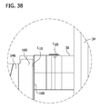
- FIG. 38 is an enlarged fragment of FIG. 37 ;
- FIG. 39 is a top plan similar to FIG. 36 , but showing a floor truss mounted in each truss hanger.
- FIG. 40 is a front view of a stamped metal blank for forming a truss hanger according to the present invention.
- a first embodiment of a connection system for a fire separation wall is shown generally at 10 .
- Floor trusses generally indicated at 12 each include truss members (broadly, “wooden structural members”) including a top chord 14 , a bottom chord 16 , and web members 18 joining the top and bottom chords.
- Each floor truss also includes end members 20 at each end joining the top and bottom chords 14 , 16 (only one end of each truss is shown).
- the truss members can be joined by nail plates 22 or by any other suitable fastening structure.
- the number and orientations of the web members 18 and chords 14 , 16 may vary from the illustrated embodiment without departing from the scope of the invention, as a truss hanger 26 according to the present invention is readily applicable to other truss configurations (e.g. a roof truss).
- the hanger 26 may be used to connect structural components other than trusses to a wall or other part of a structure.
- the hanger can be used to support other wood framing members such as solid sawn or structural composite lumber.
- a wall 28 includes a top member or plate 30 and support members or studs 32 (only one stud may be seen in FIG. 1 ).
- the top plate 30 is formed by two 2 ⁇ 4's in stacked relation.
- Fire retardant sheathing 34 is mounted on both sides of the wall 28 , as illustrated.
- the fire retardant sheathing is gypsum board, such as two layers of 5 ⁇ 8′′ gypsum board mounted on each side of the wall 28 as illustrated, although other configurations of fire retardant sheathing are within the scope of the present invention.
- Other wall configurations, including different wall constructions and materials, are within the scope of the present invention.
- the truss hangers 26 can be used with any wall assembly or fire-rated wall assembly, such as a 2-hour fire-resistive wall assembly.
- the floor trusses 12 are mounted on the wall 28 adjacent the fire retardant sheathing 34 by the truss hangers 26 .
- the truss hangers 26 extend through a narrow slot in the fire retardant sheathing 34 to maintain the integrity and fire retardant characteristics of the fire separation wall.
- the truss hanger 26 includes a channel-shaped portion 38 , an extension portion 40 , and a connection portion 42 .
- the channel-shaped portion 38 is configured to receive the floor truss 12 .
- the channel-shaped portion 38 includes a seat or base 44 and a pair of side panels 46 extending upward from the base. When installed, the base 44 is generally horizontal, and the side panels 46 extend generally vertical from the base.
- a back panel 48 extends from each of the side panels 46 . Each back panel 48 is generally perpendicular to both the side panels 46 and the base 44 . When installed, each back panel 48 extends generally parallel to an interior face 50 of the fire retardant sheathing 34 .
- the base 44 , side panels 46 , and back panels 48 form a channel 52 configured to receive the floor truss 12 .
- the floor truss 12 is received in the channel 52 to attach the floor truss to the wall 28 .
- the bottom chord 16 of the floor truss 12 engages and rests upon (i.e., is supported by) the base 44 .
- the end member 20 of the floor truss 12 is positioned against the back panels 48 between the side panels 46 .
- the truss hanger 26 includes fastening structure for attaching the floor truss 12 to the truss hanger.
- Fastening structure can be of any type known in the art for attaching a connector to a wooden structural member, such as nailing teeth (not shown) struck from the material of the hanger.
- the fastening structure comprises a hole to allow for insertion of a fastening member. More specifically, in one embodiment the fastening structure comprises nail holes 54 in the side panels 46 of the truss hanger 26 , and the fastening member comprises a nail 56 (see FIG. 12 ). In the illustrated embodiment, nail holes 54 are positioned on each of the side panels 46 so that nails 56 can be inserted into both the bottom chord 16 and the end member 20 of the floor truss 12 to attach the hanger 26 to the floor truss 12 .
- the extension portion 40 includes two extension flanges 60 configured to extend through the fire retardant sheathing 34 .
- Each flange 60 extends from one of the back panels 48 .
- the flanges 60 are positioned in opposed, face-to-face relation, and preferably engage each other along a juncture.
- Each flange 60 extends generally perpendicular from the corresponding back panel 48 and generally parallel to the side panels 46 .
- each flange 60 includes a driving point 62 .
- Each of the driving points 62 is generally triangular and includes a pointed tip 64 . As seen in FIGS. 3 and 6 , the tips 64 of the driving points 62 are vertically offset from each other.
- the tip 64 a of one flange 60 a extends vertically below the tip 64 b of the other flange 60 b .
- the tips 64 are vertically offset from each other about 1 ⁇ 8′′, although other configurations are within the scope of the present invention, such as tips that are aligned or tips that are offset a smaller or larger amount.
- a back flange 66 extends from each of the extension flanges 60 .
- Each back flange 66 extends generally perpendicular from the extension flange 60 and is oriented generally parallel to the back panels 48 .
- the back flanges 66 engage the wall 28 at a first location L 1 , which in the illustrated embodiment is a vertical face of the top plate 30 of the wall.
- the back panels 48 , extension flanges 60 , and back flanges 66 form a pair of sheathing channels 68 .
- Each sheathing channel 68 is configured to receive a portion of the fire retardant sheathing 34 to secure the sheathing between the hanger 26 and the wall 28 .
- the sheathing channels 68 extend generally perpendicular to the truss-receiving channel 52 .
- the extension flanges 60 extend through a slot 72 in the fire retardant sheathing 34 .
- the slot has an area less than or equal to 6 square inches, and the gap between the extension flanges 60 and the edge of the slot 72 is less than or equal to 1 ⁇ 8′′.
- the driving points 62 extend down into the sheathing 34 to further secure the sheathing between the hanger 26 and the wall 28 .
- a portion of the fire retardant sheathing 34 extends into each sheathing channel 68 and is secured between the back panels 48 and the back flanges 66 .
- the slot 72 in the fire retardant sheathing 34 can be made using a slot template 82 ( FIGS. 16-24 ).
- the slot template 82 includes a vertical panel 84 having a rear face 86 configured to engage the interior face 50 of the fire retardant sheathing 34 and a horizontal panel 88 having a bottom face 90 configured to engage a top face of the sheathing.
- the horizontal panel 88 extends generally perpendicular from the vertical panel 84 .
- the slot template 82 is configured to be quickly fixed in position on the sheathing 34 for use in cutting the slot 72 to receive the truss hanger 26 .
- Portions of the slot template 82 are configured to be pressed into the sheathing 34 to locate the template on the sheathing and retain the template in position for cutting the slot 72 .
- the horizontal panel includes prongs 92 that are bent downward for insertion into the top face of the sheathing 34 .
- Bottom corners 94 of the vertical panel 84 are bent rearward for insertion into the interior face 50 of the sheathing 34 .
- the prongs 92 and the corners 94 are inserted into the sheathing 34 to retain the template 82 in position for cutting the slot 72 .
- the vertical panel 84 optionally includes dimples 96 extending toward the rear face 86 of the vertical panel 84 . The dimples 96 ensure the vertical panel 84 remains slightly spaced from the interior face 50 of the sheathing 34 so the template 82 can be easily removed from the sheathing after the slot 72 is cut.
- the template 82 includes a guide slot 98 to guide a cutting tool in cutting the slot 72 in the sheathing 34 .
- the guide slot 98 extends from a top edge of the vertical panel 84 to a location spaced from a bottom edge of the vertical panel.
- the guide slot 98 includes a wide, rectangular portion 98 a in the horizontal panel 88 to ease insertion of a cutting tool into the guide slot.
- a converging portion 98 b of the slot 98 in the vertical panel 84 transitions from the wide portion 98 a to a narrow lower portion 98 c of the slot. This facilitates entry of the cutting tool into the narrow portion 98 c .
- the narrow portion 98 c of the guide slot 98 is dimensioned to facilitate cutting the slot 72 in the sheathing 34 to a size configured to receive the extension flanges 60 of the truss hanger 26 .
- the template 82 described above can be formed as one piece from a metal blank 100 that is stamped from a sheet metal roll and bent into shape.
- the template 82 is stamped from 16 gauge steel, although other thicknesses (e.g., 12-18 gauge) and other suitable materials are within the scope of the present invention.
- the template 82 is placed on the sheathing 34 in a selected location for a slot 72 .
- the template can be used to cut the slot 72 in the sheathing 34 either before or after the sheathing is mounted on the wall 28 .
- the prongs 92 and corners 94 are inserted into the sheathing 34 by tapping with a hand or striking with a hammer or other blunt instrument.
- a cutting tool e.g., a drywall cutout tool
- a drywall cutout tool with a 1 ⁇ 8′′ or 1 ⁇ 4′′ spiral bit is used to cut the slot 72 , although other cutting tools are within the scope of the present invention.
- the template 82 is removed from the sheathing.
- the sheathing 34 is then configured to receive the truss hanger 26 .
- connection portion of the hanger includes a pair of connector tabs 74 extending from the back flanges 66 .
- Each connector tab 74 extends generally perpendicular from one of the back flanges 66 .
- the connector tabs 74 are generally horizontal when the hanger 26 is installed.
- the connector tabs 74 are configured to engage an upper surface of the top plate 30 of the wall 28 at a second location L 2 spaced from the first location L 1 .
- the connector tabs 74 can be used to attach the truss hanger 26 to the wall, thereby hanging the floor trusses 12 from the wall. As seen in FIG. 1 , the connector tabs 74 extend over a portion of the top plate 30 of the wall 28 .
- Each connector tab 74 includes fastening structure, such as nail holes 76 , for insertion of a fastening member, such as nails 78 (see FIGS. 10 and 10A ), to attach the hanger 26 to the wall 28 .
- a fastening member such as nails 78 (see FIGS. 10 and 10A )
- each connector tab 74 includes three nail holes 76 .
- Other configurations are within the scope of the present invention, such as a different number of nail holes, or alternate fastening structure such as nailing teeth or other appropriate structure for fastening the hanger to the wall.
- the base 44 and back flanges 66 of the truss hanger 26 cooperate to stabilize the truss hanger 26 and protect the fire retardant sheathing 34 under the loads transferred from the truss 12 to the wall 28 by way of the hanger.
- the channel 52 that receives an end portion of the truss 12 is spaced to the interior of the wall 28 and more particularly to the interior of the second location L 2 where the connector tabs 74 are attached to an upper surface of the top plate 30 .
- a truss hanger 26 as described above can be formed as one piece from a metal blank 80 that is stamped from a sheet metal roll and bent into shape.
- the truss hanger 26 is stamped from 12-14 gauge steel, although other suitable materials are within the scope of the present invention.
- the configuration of the truss hanger 26 of the present invention allows a lighter gauge metal to be used.
- the truss hanger 26 is positioned in the slot 72 of the fire retardant sheathing 34 mounted on the wall 28 .
- one method of using the truss hanger 26 includes cutting the slot 72 in the fire retardant sheathing 34 (either before or after the sheathing is mounted on the wall).
- the slot 72 can be cut using the slot template 82 (either before or after the sheathing 34 is mounted to the wall 28 ).
- the slot can be any suitable length, and in one embodiment is about 10 inches long.
- the truss hanger 26 is then positioned against the fire retardant sheathing 34 so that the extension flanges 60 extend through the slot 72 .
- the hanger 26 is slid downward into place so that the extension flanges 60 extend through the slot 72 , the back flanges 66 are positioned adjacent the wall 28 , and the fire retardant sheathing 34 is positioned in the sheathing channels 68 between the back flanges and the back panels 48 .
- the hanger connector tabs 74 are fastened to the top plate 30 of the wall 28 by any suitable means, such as by inserting nail 78 through the nail holes 76 .
- a truss member e.g. truss bottom chord 16 , is positioned in the truss channel 52 of the hanger 26 (see FIG. 1 ), thereby securing the floor truss 12 to the wall 28 .
- the truss hanger 26 is then fastened to the truss 12 by any suitable means, such as by inserting nails 56 through the nail holes 54 in each side panel 46 of the hanger.
- the hanger 26 is thus secured to both the truss 12 and the wall 28 , with the fire retardant sheathing 34 secured between the hanger and the wall.
- the truss hangers 26 can be installed without pre-forming the slot 72 in the fire retardant sheathing 34 . More particularly, each hanger 26 can be driven into the sheathing 34 . The driving point 62 of the hanger 26 is positioned against a top edge of the fire retardant sheathing. The hanger 26 is then driven downward into the sheathing 34 , led by the pointed tip 64 . The hanger 26 continues to be driven into the gypsum boards until the connector tabs 74 engage the upper surface of the top plate 30 . In this way, the hanger 26 forms the slot in the sheathing 34 .
- the truss hangers 26 can be installed on the wall 28 before the sheathing 34 is mounted on the wall. This simplifies construction by allowing the building to be completely framed and roofed before requiring the sheathing 34 to be installed. Trade workers (e.g., mechanical, electrical) therefore have complete access to the wall cavity to install components without interference from the sheathing 34 .
- the truss hanger 26 is positioned against the wall 28 such that the back flanges 66 engage the wall and the connector tabs 74 engage the top plate 30 .
- the connector tabs 74 are fastened to the top plate 30 of the wall by any suitable means, such as by inserting nails 78 through nail holes 76 .
- a truss 12 is positioned in the truss channel 52 of the hanger 26 .
- the truss hanger is fastened to the truss 12 by any suitable means, such as by inserting nails 56 through the nail holes 54 in each side panel 46 of the hanger 26 .
- the floor truss 12 is thereby secured to the hanger 26 and the wall 28 , and access to the wall cavity remains unhindered by sheathing.
- the sheathing 34 can be mounted on the wall 28 by moving the sheathing upward into place so that the extension flanges 60 of the hanger 26 extend through the slot 72 of the sheathing and the sheathing is positioned in the sheathing channels 68 between the back flanges 66 and the back panels 48 .
- a second embodiment of a truss hanger 126 for use in mounting the floor truss 12 to the wall 28 is illustrated.
- the truss hanger 126 is similar to the truss hanger 26 described above, with differences as pointed out herein. Where the truss hanger 26 is configured for mounting the floor truss 12 generally orthogonal to the wall 28 , the truss hanger 126 is configured for mounting the floor truss 12 in a skewed position relative to the wall.
- the truss hanger 126 includes a channel-shaped portion 138 , an extension portion 140 , and a connection portion 142 .
- the channel-shaped portion 138 is configured to receive the floor truss 12 .
- the channel-shaped portion 138 is configured to support the floor truss 12 at a non-orthogonal angle relative to the wall 28 . In this skewed embodiment, the channel-shaped portion 138 is offset from the extension portion 140 .
- the channel-shaped portion 138 includes a seat or base 144 and a pair of side panels 146 extending upward from the base. When installed, the base 144 is generally horizontal, and the side panels 146 extend generally vertical from the base.
- a back panel 148 extends from one of the side panels 146 a toward the opposing side panel 146 b .
- the back panel 148 is generally perpendicular to both the side panels 146 and the base 144 .
- the back panel 148 extends at a non-orthogonal angle (e.g., about 45°) to the interior face 50 of the fire retardant sheathing 34 .
- the base 144 , side panels 146 , and back panel 148 form a channel 152 configured to receive the floor truss 12 .
- Other configurations are within the scope of the present invention.
- the truss hanger 126 can be configured to support the floor truss 12 at a range of different angles with respect to the wall 28 .
- the floor truss 12 is received in the channel 152 to attach the floor truss to the wall 28 at a skewed angle.
- the bottom chord 16 of the floor truss 12 engages and rests upon (i.e., is supported by) the base 144 .
- the end member 20 of the floor truss 12 is positioned against the back panel 148 between the side panels 146 .
- the truss hanger 126 includes fastening structure for attaching the floor truss 12 to the truss hanger.
- Fastening structure can be of any type known in the art for attaching a connector to a wooden structural member, such as nailing teeth (not shown) struck from the material of the hanger.
- the fastening structure comprises a hole to allow for insertion of a fastening member. More specifically, in one embodiment the fastening structure comprises nail holes 154 in the side panels 146 of the truss hanger 126 (see, FIG. 26 ), and the fastening member comprises a nail 156 (see, FIG. 25 ). In the illustrated embodiment, nail holes 154 are positioned on each of the side panels 146 so that nails 156 can be inserted into both the bottom chord 16 and the end member 20 of the floor truss 12 to attach the hanger 126 to the floor truss.
- the extension portion 140 includes two extension flanges 160 configured to extend through the fire retardant sheathing 34 .
- One of the flanges 160 a extends from the back panel 148 .
- the other flange 160 b extends from the side panel 146 b .
- the flanges 160 are positioned in opposed, face-to-face relation, and preferably engage each other along a juncture.
- each flange 160 includes a driving point 162 .
- Each of the driving points 162 is generally triangular and includes a pointed tip 164 . As seen in FIG. 28 , the tips 164 of the driving points 162 are vertically offset from each other.
- the tip 164 a of one flange 160 a extends vertically below the tip 164 b of the other flange 160 b .
- the tips 164 are vertically offset from each other about 1 ⁇ 8′′, although other configurations are within the scope of the present invention, such as tips that are aligned or tips that are offset a smaller or larger amount.
- a back flange 166 extends from the extension flange 160 generally perpendicular from the extension flange. Referring to FIG. 38 , the back flange 166 engages the wall 28 at a first location L 10 , which in the illustrated embodiment is a vertical face of the top plate 30 of the wall behind the fire retardant sheathing 34 .
- the back flange 166 comprises a back flange portion 166 a bent from the extension flange 160 a and a back flange portion 166 b bent from the extension flange 160 b .
- the back panel 148 , side panel 146 b , extension flanges 160 , and back flange 166 form a pair of sheathing channels 168 (see, FIG. 32 ). Each sheathing channel 168 is configured to receive a portion of the fire retardant sheathing 34 .
- the extension flanges 160 extend through the slot 72 in the fire retardant sheathing 34 .
- the slot has an area less than or equal to 6 square inches, and the gap between the extension flanges 60 and the edge of the slot 72 is less than or equal to 1 ⁇ 8′′.
- the driving points 162 extend down into the sheathing 34 to engage the sheathing and further secure the sheathing between the hanger 126 and the wall 28 .
- a portion of the fire retardant sheathing 34 extends into each sheathing channel 168 and is secured against the back flange 166 .
- connection portion 142 of the hanger 126 includes a pair of connector tabs 174 extending from the back flange portions 166 a , 166 b .
- Each connector tab 174 extends generally perpendicular from a respective one of the back flanges 166 a , 166 b .
- the connector tabs 174 are generally horizontal when the hanger 126 is installed.
- the connector tabs 174 are configured to overlie and engage an upper surface of the top plate 30 of the wall 28 at a second location L 20 spaced from the first location L 10 (see, FIGS. 37 and 38 ).
- the connector tabs 174 can be used to attach the truss hanger 126 to the wall 28 , thereby hanging the floor trusses 12 from the wall. As seen in FIG. 25 , the connector tabs 174 extend over a portion of the top plate 30 of the wall 28 .
- Each connector tab 174 includes fastening structure, such as nail holes 176 , for insertion of a fastening member, such as nails 178 (see FIGS. 34 and 35 ), to attach the hanger 126 to the wall 28 .
- each connector tab 174 includes three nail holes 176 .
- Other configurations are within the scope of the present invention, such as a different number of nail holes, or alternate fastening structure such as nailing teeth or other appropriate structure for fastening the hanger to the wall.
- the base 144 and back flanges 166 cooperate to stabilize the truss hanger 126 and protect the fire retardant sheathing 34 from exposure to the loads transferred from the truss 12 to the wall 28 by way of the truss hanger 126 .
- the channel 152 that receives an end portion of the truss 12 is spaced to the interior of the wall 28 and more particularly to the interior of the second location L 20 where the connector tabs 174 are attached to an upper surface of the top plate 30 (see FIG. 38 ).
- a truss hanger 126 as described above can be formed as one piece from a metal blank 180 that is stamped from a sheet metal roll and bent into shape. Parts of the blank 180 are labelled with reference numerals corresponding to the various parts of the formed truss hanger 126 .
- the truss hanger 126 is stamped from 12-14 gauge steel, although other suitable materials are within the scope of the present invention.
- the configuration of the truss hanger 126 of the present invention allows a lighter gauge metal to be used.
- the truss hanger 126 is used as described above with reference to the truss hanger 26 . In use, the truss hanger 126 is positioned in the slot 72 of the fire retardant sheathing 34 mounted to the wall 28 .
- One method of using the truss hanger 126 includes cutting the slot 72 in the fire retardant sheathing (either before or after the sheathing is mounted on the wall). In one embodiment, the slot 72 can be cut using the slot template 82 (either before or after the sheathing 34 is mounted to the wall 28 ).
- the slot 72 can be any suitable length, and in one embodiment is about 10 inches long.
- the truss hanger 126 is then positioned against the fire retardant sheathing 34 so that the extension flanges 160 extend through the slot 72 .
- the hanger 126 is slid downward into place so that the extension flanges 160 extend through the slot 72 , the driving point 162 engages the fire retardant sheathing 34 , the back flange 166 is positioned adjacent the wall 28 , and the fire retardant sheathing is positioned in the sheathing channels 168 of the hanger.
- the hanger connector tabs 174 are fastened to the top plate 30 of the wall 28 by driving nails 178 through the nail holes 176 into the top plate 30 .
- a truss member e.g.
- truss bottom chord 16 is positioned in the truss channel 152 of the hanger 126 .
- Nails 156 are driven through holes 154 in the side panels 146 to secure the floor truss 12 to the wall 28 .
- the hanger 126 is thus secured to both the truss 12 and the wall 28 , with the fire retardant sheathing 34 between the hanger and the wall.
- the truss hangers 126 can be installed without pre-forming the slot 72 in the fire retardant sheathing 34 . More particularly, each hanger 126 can be driven into the sheathing 34 . The pointed tip 164 of the driving point 162 of the hanger 126 is positioned against a top edge of the fire retardant sheathing 34 . The hanger 126 is then driven downward into the sheathing 34 , led by the pointed tip 164 . The hanger 126 continues to be driven into the gypsum boards until the connector tabs 174 engage the upper surface of the top plate 30 . In this way, the hanger 126 forms the slot in the sheathing 34 .
- the truss hangers 126 can be installed on the wall 28 before the sheathing 34 is mounted on the wall. This simplifies construction by allowing the building to be completely framed and roofed before requiring the sheathing 34 to be installed. Trade workers (e.g., mechanical, electrical) therefore have complete access to the wall cavity to install components without interference from the sheathing 34 .
- the truss hanger 126 is positioned against the wall 28 such that the back flange 166 engages the wall and the connector tabs 174 engage the top plate 30 .
- the connector tabs 174 are fastened to the top plate 30 of the wall by any suitable means, such as by inserting nails 178 through nail holes 176 .
- a truss 12 is positioned in the truss channel 152 of the hanger 126 .
- the truss hanger 126 is fastened to the truss 12 by any suitable means, such as by inserting nails 156 through the nail holes 154 in each side panel 146 of the hanger.
- the floor truss 12 is thereby secured to the hanger 126 and the wall 28 , and access to the wall cavity remains unhindered by sheathing.
- the sheathing 34 can be mounted on the wall 28 by moving the sheathing upward into place so that the extension flanges 160 of the hanger 126 extend through the slot 72 of the sheathing and the sheathing is positioned in the sheathing channels 168 of the hanger.
- the truss hanger 26 , 126 permits a floor truss 12 to be secured to a wall 28 through fire retardant sheathing 34 with minimal interruption to the sheathing. Installation of the truss hanger minimally disrupts the continuity of the sheathing and therefore does not reduce the fire resistive rating of a fire rated assembly.
- the extension flanges 60 , 160 extend through the fire retardant sheathing 34 so that the sheathing is interrupted only by the slot 72 required to receive the flanges.
- the back flanges 66 , 166 engage the wall 28 behind the sheathing 34 to stabilize the hanger 26 , 126 and protect the sheathing.
- the truss hanger 26 , 126 can be mounted on a wall already having sheathing mounted thereon, or can be mounted on a wall before the sheathing (i.e., the sheathing does not have to be mounted on the wall before the truss hanger), thereby simplifying construction.
- the truss hanger 26 , 126 can be formed from a metal blank 80 , 180 , which reduces the number of parts required to hang the floor truss 12 and simplifies the manufacturing process.
- the truss hanger was installed as part of a wall assembly including 2 ⁇ 6 wood studs, 24′′ on center, with two layers of 5 ⁇ 8′′ Type X gypsum attached to each side.
- the gypsum board included a slot to accommodate the hanger.
- the hanger was fixed to the top plate of the wall with six 10d common nails in the connector tabs.
- the cavities in the wall were filled with mineral wool insulation. The testing was performed per ASTM E814 which subjected the specimen to the time/temperature curve prescribed in ASTM E119 for a period of two hours, followed by a hose stream test.
Landscapes
- Engineering & Computer Science (AREA)
- Architecture (AREA)
- Physics & Mathematics (AREA)
- Electromagnetism (AREA)
- Civil Engineering (AREA)
- Structural Engineering (AREA)
- Building Environments (AREA)
Priority Applications (8)
| Application Number | Priority Date | Filing Date | Title |
|---|---|---|---|
| US14/555,049 US10024049B2 (en) | 2013-12-31 | 2014-11-26 | Hanger for fire separation wall |
| US15/675,409 US10184242B2 (en) | 2013-12-31 | 2017-08-11 | Hanger for fire separation wall |
| US16/225,517 US10316510B2 (en) | 2013-12-31 | 2018-12-19 | Hanger for fire separation wall |
| US16/433,799 US11021867B2 (en) | 2013-12-31 | 2019-06-06 | Hanger for fire separation wall |
| US17/235,349 US11649626B2 (en) | 2013-12-31 | 2021-04-20 | Hanger for fire separation wall |
| US18/112,843 US11920339B2 (en) | 2013-12-31 | 2023-02-22 | Method of constructing a fire-resistive wall assembly |
| US18/492,460 US20240052624A1 (en) | 2013-12-31 | 2023-10-23 | Hanger for fire separation wall |
| US18/520,333 US20240093481A1 (en) | 2013-12-31 | 2023-11-27 | Hanger for fire separation wall |
Applications Claiming Priority (2)
| Application Number | Priority Date | Filing Date | Title |
|---|---|---|---|
| US201361922531P | 2013-12-31 | 2013-12-31 | |
| US14/555,049 US10024049B2 (en) | 2013-12-31 | 2014-11-26 | Hanger for fire separation wall |
Related Child Applications (1)
| Application Number | Title | Priority Date | Filing Date |
|---|---|---|---|
| US15/675,409 Continuation US10184242B2 (en) | 2013-12-31 | 2017-08-11 | Hanger for fire separation wall |
Publications (2)
| Publication Number | Publication Date |
|---|---|
| US20150184370A1 US20150184370A1 (en) | 2015-07-02 |
| US10024049B2 true US10024049B2 (en) | 2018-07-17 |
Family
ID=53481099
Family Applications (8)
| Application Number | Title | Priority Date | Filing Date |
|---|---|---|---|
| US14/555,049 Active 2035-01-08 US10024049B2 (en) | 2013-12-31 | 2014-11-26 | Hanger for fire separation wall |
| US15/675,409 Active US10184242B2 (en) | 2013-12-31 | 2017-08-11 | Hanger for fire separation wall |
| US16/225,517 Active US10316510B2 (en) | 2013-12-31 | 2018-12-19 | Hanger for fire separation wall |
| US16/433,799 Active US11021867B2 (en) | 2013-12-31 | 2019-06-06 | Hanger for fire separation wall |
| US17/235,349 Active 2035-02-09 US11649626B2 (en) | 2013-12-31 | 2021-04-20 | Hanger for fire separation wall |
| US18/112,843 Active US11920339B2 (en) | 2013-12-31 | 2023-02-22 | Method of constructing a fire-resistive wall assembly |
| US18/492,460 Pending US20240052624A1 (en) | 2013-12-31 | 2023-10-23 | Hanger for fire separation wall |
| US18/520,333 Pending US20240093481A1 (en) | 2013-12-31 | 2023-11-27 | Hanger for fire separation wall |
Family Applications After (7)
| Application Number | Title | Priority Date | Filing Date |
|---|---|---|---|
| US15/675,409 Active US10184242B2 (en) | 2013-12-31 | 2017-08-11 | Hanger for fire separation wall |
| US16/225,517 Active US10316510B2 (en) | 2013-12-31 | 2018-12-19 | Hanger for fire separation wall |
| US16/433,799 Active US11021867B2 (en) | 2013-12-31 | 2019-06-06 | Hanger for fire separation wall |
| US17/235,349 Active 2035-02-09 US11649626B2 (en) | 2013-12-31 | 2021-04-20 | Hanger for fire separation wall |
| US18/112,843 Active US11920339B2 (en) | 2013-12-31 | 2023-02-22 | Method of constructing a fire-resistive wall assembly |
| US18/492,460 Pending US20240052624A1 (en) | 2013-12-31 | 2023-10-23 | Hanger for fire separation wall |
| US18/520,333 Pending US20240093481A1 (en) | 2013-12-31 | 2023-11-27 | Hanger for fire separation wall |
Country Status (2)
| Country | Link |
|---|---|
| US (8) | US10024049B2 (fr) |
| CA (3) | CA3038336C (fr) |
Cited By (8)
| Publication number | Priority date | Publication date | Assignee | Title |
|---|---|---|---|---|
| US11142902B2 (en) | 2017-06-07 | 2021-10-12 | Simpson Strong-Tie Company, Inc. | Drywall hanger |
| USRE48789E1 (en) | 2013-12-14 | 2021-10-26 | Simpson Strong-Tie Company Inc. | Drywall joist hanger |
| US11225787B2 (en) | 2018-06-06 | 2022-01-18 | Simpson Strong-Tie Company, Inc. | Drywall spacing joist hanger |
| US11274459B2 (en) | 2020-05-05 | 2022-03-15 | Colhurst Concepts, LLC | Temporary pool cover and floor system |
| US11499328B2 (en) * | 2020-05-05 | 2022-11-15 | Colhurst Concepts, LLC | Temporary pool cover and floor system |
| US11773582B2 (en) | 2020-07-01 | 2023-10-03 | Omg, Inc. | Expandable hanger for beam |
| US12338619B2 (en) | 2021-06-27 | 2025-06-24 | Paul Matthews Mosher | Mass timber hanger |
| US12559932B2 (en) | 2023-06-21 | 2026-02-24 | Jenwest Enterprises LLC | Joist hanger |
Families Citing this family (7)
| Publication number | Priority date | Publication date | Assignee | Title |
|---|---|---|---|---|
| US10024049B2 (en) * | 2013-12-31 | 2018-07-17 | Columbia Insurance Company | Hanger for fire separation wall |
| US10179992B2 (en) * | 2016-08-08 | 2019-01-15 | Columbia Insurance Company | Heavy duty hanger for fire separation wall |
| US10358812B2 (en) * | 2017-06-16 | 2019-07-23 | Jenwest Enterprises LLC | Joist hanger |
| EP3911803A1 (fr) | 2019-01-14 | 2021-11-24 | Simpson Strong-Tie Company, Inc. | Connecteur à charnière renforcé |
| US11821199B2 (en) * | 2019-12-19 | 2023-11-21 | Columbia Insurance Company | Girder tie |
| US12163337B2 (en) * | 2021-10-07 | 2024-12-10 | 1947742 Alberta Ltd. | Cladding installation support |
| US20240376704A1 (en) * | 2023-05-12 | 2024-11-14 | Simpson Strong-Tie Company Inc. | Drywall Spacing Joist Hanger |
Citations (85)
| Publication number | Priority date | Publication date | Assignee | Title |
|---|---|---|---|---|
| US414169A (en) * | 1889-10-29 | William reuschel | ||
| US478163A (en) * | 1892-07-05 | Wrought-metal hanger for joists | ||
| US537504A (en) * | 1895-04-16 | Wrought-metal joist-hanger | ||
| US546147A (en) * | 1895-09-10 | T txtt | ||
| US598135A (en) * | 1898-02-01 | John a | ||
| US625427A (en) * | 1899-05-23 | Wrought-metal joist-hanger | ||
| US666918A (en) * | 1900-05-17 | 1901-01-29 | John A Butz | Stirrup or hanger for floor-beams. |
| US717316A (en) * | 1902-05-10 | 1902-12-30 | Avery Stamping Company | Joist-hanger. |
| US753053A (en) * | 1904-02-23 | Joist-hanger | ||
| US770050A (en) * | 1904-04-18 | 1904-09-13 | William D Dreyer | Joist-hanger. |
| US783807A (en) * | 1902-07-28 | 1905-02-28 | Julius Tuteur | Joist-hanger. |
| US796433A (en) * | 1904-10-19 | 1905-08-08 | Julius Kahn | Joist-hanger. |
| US804451A (en) * | 1905-03-29 | 1905-11-14 | Lucien L Gervais | Joist-hanger. |
| US828488A (en) * | 1905-05-06 | 1906-08-14 | John Lanz | Method of making joist-hangers. |
| US874514A (en) * | 1907-05-31 | 1907-12-24 | Wesley F Lindow | Joist-hanger. |
| US922215A (en) * | 1909-05-18 | Julius Tuteur | Hanger for joists. | |
| US924842A (en) * | 1908-04-06 | 1909-06-15 | Henry C Seipp | Joist-hanger. |
| US943847A (en) * | 1909-02-20 | 1909-12-21 | Henry C Seipp | Joist-hanger. |
| US1406723A (en) * | 1920-04-03 | 1922-02-14 | United Alloy Steel Corp | Joist hanger |
| US1728981A (en) * | 1927-04-30 | 1929-09-24 | Franklin N Ropp | Joist hanger for concrete buildings |
| US3125785A (en) * | 1964-03-24 | Conville | ||
| US3907445A (en) * | 1975-01-06 | 1975-09-23 | United States Gypsum Co | Self-aligning joist hanger for structural steel framing |
| US3945741A (en) * | 1975-01-06 | 1976-03-23 | United States Gypsum Company | Self-aligning hanger attachment bracket for structural steel joists |
| US3972169A (en) | 1976-01-12 | 1976-08-03 | Sheppard Jr Isaac | Saddle hanger |
| US4005942A (en) | 1976-03-22 | 1977-02-01 | Simpson Manufacturing Co., Inc. | Metal hanger |
| US4198175A (en) * | 1978-10-03 | 1980-04-15 | Morton Buildings, Inc. | Timber connectors |
| US4223866A (en) * | 1977-05-10 | 1980-09-23 | Brown Company | Adjustable bracket |
| US4230416A (en) * | 1979-10-15 | 1980-10-28 | Simpson Manufacturing Co., Inc. | Restricted slot nail openings for sheet metal framing connectors |
| US4261155A (en) * | 1979-11-16 | 1981-04-14 | Simpson Manufacturing Co., Inc. | Infinite skewed hanger |
| US4353664A (en) * | 1980-07-24 | 1982-10-12 | Simpson Manufacturing Co., Inc. | Free gusset metal ledger hanger |
| US4411548A (en) * | 1981-06-08 | 1983-10-25 | P. H. Bowman Co., Inc. | Joist hanger |
| US4422792A (en) * | 1982-08-16 | 1983-12-27 | Simpson Strong-Tie Company, Inc. | Gusset metal ledger hanger |
| US4472916A (en) * | 1980-06-02 | 1984-09-25 | Arthur Krebs | Pre-fabricated house construction |
| US4560301A (en) * | 1984-01-03 | 1985-12-24 | Simpson Strong-Tie, Company, Inc. | Heavy slope and skew sheet metal hanger and method of making same |
| US4584813A (en) * | 1983-04-18 | 1986-04-29 | Hudson John T | Method for installing a hanger for a structural member |
| US4594017A (en) * | 1985-06-17 | 1986-06-10 | Altech Industries, Inc. | Joist hanger and blank therefor |
| US4665672A (en) * | 1985-03-20 | 1987-05-19 | Simpson Strong-Tie Company, Inc. | One piece, non-welded holdown |
| US4920725A (en) * | 1989-02-14 | 1990-05-01 | Truswal Systems Corporation | Self-gripping hanger device |
| US5104252A (en) * | 1991-10-31 | 1992-04-14 | Simpson Strong-Tie Company, Inc. | Hanger connection |
| US5111632A (en) | 1990-09-06 | 1992-05-12 | Turner Arthur R | Expandable joist hanger |
| US5160211A (en) * | 1990-11-13 | 1992-11-03 | Simpson Strong-Tie Company, Inc. | Post to railing tie |
| US5230198A (en) * | 1992-10-29 | 1993-07-27 | United Steel Products Co. | Variable pitch connector |
| US5249404A (en) * | 1992-05-11 | 1993-10-05 | Simpson Strong-Tie Company, Inc. | Holdown connection |
| US5341619A (en) * | 1993-04-09 | 1994-08-30 | Simpson Strong-Tie Company, Inc. | Truss girder hanger connection |
| US5457928A (en) * | 1994-04-01 | 1995-10-17 | Mga Construction Hardware And Steel Fabricating Ltd. | Slope and skew hanger connectors |
| US5555694A (en) * | 1995-01-27 | 1996-09-17 | Simpson Strong-Tie Company, Inc. | Structural hanger |
| US5564248A (en) * | 1994-11-10 | 1996-10-15 | United Steel Products Company | Construction hanger and method of making the same |
| US5603580A (en) * | 1995-05-30 | 1997-02-18 | Simpson Strong-Tie Company, Inc. | Positive angle fastener device |
| US5697725A (en) * | 1996-06-18 | 1997-12-16 | Simpson Strong-Tie Company, Inc. | Stud to plate tie |
| US5797694A (en) * | 1996-03-29 | 1998-08-25 | Alpine Engineered Products, Inc. | Adjustable ridge connector |
| US5896721A (en) * | 1996-11-19 | 1999-04-27 | West Company Limited | Metal device for joining wooden members in wooden building |
| US6131358A (en) * | 1997-08-29 | 2000-10-17 | Wise; Michael A. | Joist hanger and installation method |
| US6230466B1 (en) | 1998-10-13 | 2001-05-15 | Simpson Strong-Tie Company, Inc. | Wrap around hanger |
| US20020078656A1 (en) * | 1999-08-27 | 2002-06-27 | Simpson Strong-Tie Company, Inc. | Snap-in hanger |
| US6463711B1 (en) * | 1999-08-09 | 2002-10-15 | United Steel Products Company, Inc. | Construction hanger |
| US20040096269A1 (en) * | 2002-11-20 | 2004-05-20 | George Shahnazarian | Joist hangers |
| US20040129845A1 (en) * | 2001-05-19 | 2004-07-08 | Whale Luke John Richard | Hanger device |
| US6877291B2 (en) * | 2001-10-30 | 2005-04-12 | Simpson Strong-Tie Company, Inc. | Strap holding device |
| US20050120669A1 (en) | 2003-10-20 | 2005-06-09 | Ian Harrison | Bottom flange hanger |
| US20060081743A1 (en) | 2004-10-15 | 2006-04-20 | Evans Thomas G | Top flange hanger with strengthening embossment |
| US20060156682A1 (en) | 2005-01-04 | 2006-07-20 | Cullen Building Products Limited | Hanger |
| US20060191233A1 (en) | 2005-02-28 | 2006-08-31 | R. H. Tamlyn & Sons, Lp | Nail Receiving Fastener Device |
| US20070119108A1 (en) * | 2005-11-14 | 2007-05-31 | Downard Evan M | End cap for wood frame construction |
| US20070294979A1 (en) | 2006-06-26 | 2007-12-27 | Jin-Jie Lin | Hanger with gripping tabs |
| US7316098B1 (en) | 2004-09-07 | 2008-01-08 | Sackett Gerald L | Device and method for interconnecting framing components |
| US20080101855A1 (en) * | 2006-10-31 | 2008-05-01 | Jin-Jie Lin | Nail guide with curved opening |
| US20080237421A1 (en) | 2006-11-02 | 2008-10-02 | Adam Szpotowski | Hangers |
| US20090113839A1 (en) | 2007-09-25 | 2009-05-07 | Michael Norman Carr | Adjustable joist hanger |
| US20100031601A1 (en) | 2006-10-18 | 2010-02-11 | Jin-Jie Lin | Wide back flange hanger |
| US7707785B2 (en) * | 2006-10-31 | 2010-05-04 | Simpson Strong-Tie Company, Inc. | Variable girder tie |
| US20110146173A1 (en) | 2009-12-22 | 2011-06-23 | VISSER Michael | Wall system for a building |
| US7971410B2 (en) * | 2007-07-18 | 2011-07-05 | Alvin Jerke | Hurricane framing tie |
| WO2012060863A2 (fr) | 2010-11-01 | 2012-05-10 | Moses Allen R | Construction de panneaux assemblés sur place, et procédé d'assemblage sur place |
| US20120222382A1 (en) * | 2011-03-01 | 2012-09-06 | Steve Brekke | Structural Support Device with Web Brace |
| US20120297724A1 (en) | 2011-05-24 | 2012-11-29 | Mitek Holdings, Inc. | Saddle hanger for a structure |
| US20130067850A1 (en) | 2011-09-20 | 2013-03-21 | Tallmadge Spinning & Metal Company | Joist hanger |
| WO2013126987A1 (fr) | 2012-02-28 | 2013-09-06 | Michael Hatzinikolas | Assemblage structurel à déclenchement automatique |
| US20130232758A1 (en) * | 2012-03-06 | 2013-09-12 | Inter-Med, Inc. | Bracket Assembly and Systems |
| US8677718B2 (en) | 2011-05-02 | 2014-03-25 | Joseph T. Marshall | Retrofit mounting clip for an exterior building surface |
| US8720155B1 (en) | 2009-10-23 | 2014-05-13 | Glenn Robell | Method and system of framing components and hangers used in a structural interface |
| US20140338282A1 (en) | 2013-05-17 | 2014-11-20 | Global Utility Patent Corp. | Modular joist brace bracket |
| US20150167291A1 (en) * | 2013-12-14 | 2015-06-18 | Simpson Strong-Tie Company, Inc. | Drywall joist hanger |
| US20150218832A1 (en) | 2014-02-05 | 2015-08-06 | Jake M. Peters | Frame hanger jig apparatus |
| US9206594B1 (en) * | 2014-09-04 | 2015-12-08 | Columbia Insurance Company | Hanger with locator tooth |
| US20170321418A1 (en) * | 2014-12-02 | 2017-11-09 | Rhèal THIBAULT | Fire-resistant construction panel |
Family Cites Families (41)
| Publication number | Priority date | Publication date | Assignee | Title |
|---|---|---|---|---|
| US784218A (en) * | 1904-09-21 | 1905-03-07 | Lane Brothers Company | Joist-hanger. |
| US1792815A (en) | 1930-04-30 | 1931-02-17 | S M Siesel Co | Construction-element extension hanger |
| US3088558A (en) | 1958-11-17 | 1963-05-07 | Harvey Aluminum Inc | Prefabricated building assembly |
| US3298651A (en) | 1966-03-07 | 1967-01-17 | La Roy B Passer | Wall hanger |
| US3601428A (en) | 1969-12-11 | 1971-08-24 | Simpson Co | Pronged joist hanger |
| US3633950A (en) | 1970-10-08 | 1972-01-11 | Simpson Co | Grip groove hanger |
| US3752512A (en) * | 1972-01-24 | 1973-08-14 | Simpson Co | Single-thickness seat hanger |
| US3989398A (en) * | 1975-01-06 | 1976-11-02 | United States Gypsum Company | Clip-on attachment members for structural steel joists |
| GB2062058A (en) | 1979-10-10 | 1981-05-20 | Press Bat Holdings Ltd | Joist hanger |
| US4423977A (en) * | 1982-03-22 | 1984-01-03 | Simpson Strong-Tie Company, Inc. | Single element slope and skew hanger |
| US4480941A (en) | 1983-03-04 | 1984-11-06 | Simpson Strong-Tie Company, Inc. | Double shear angled fastener connector |
| GB8423482D0 (en) | 1984-09-17 | 1984-10-24 | Press Bat Holdings Ltd | Joist hanger |
| DE3677660D1 (de) | 1985-07-23 | 1991-04-04 | Press Bat Holdings Ltd | Verbinder fuer holzbalken, verbinder mit befestigungsbuegel und verbinderpaar mit zusammenhaltebuegel. |
| JPH0314482Y2 (fr) | 1986-04-03 | 1991-03-29 | ||
| US4714372A (en) * | 1986-08-18 | 1987-12-22 | Simpson Strong-Tie Company, Inc. | Hurricane tie |
| US4709527A (en) * | 1986-10-21 | 1987-12-01 | John Cooley | Sheetrock hanging tool |
| US4717279A (en) | 1987-04-21 | 1988-01-05 | Simpson Strong-Tie Company, Inc. | Bucket hanger |
| US4827684A (en) | 1988-03-17 | 1989-05-09 | Aa Wire Products Company | Masonry veneer wall anchor |
| FR2646836B1 (fr) | 1989-05-12 | 1991-08-30 | Raison Pure Sa | Etui pour baton de substance non fluide, applicable par frottement sur une surface |
| US4893961A (en) * | 1989-06-05 | 1990-01-16 | Trus Joist Corporation | Joist hanger |
| US5004369A (en) | 1989-06-23 | 1991-04-02 | United Steel Products Co. | Slope and skew hanger |
| US5217317A (en) * | 1989-06-23 | 1993-06-08 | United Steel Products Company | Bracket with angled nailing feature |
| JPH05171718A (ja) | 1991-12-19 | 1993-07-09 | Misawa Homes Co Ltd | 梁取付装置 |
| US5220766A (en) | 1991-12-30 | 1993-06-22 | Southeastern Metals Mfg. Co., Inc. | Skewed beam hanger |
| US5423156A (en) * | 1993-08-23 | 1995-06-13 | Nellessen, Jr.; Peter | Sheathing strap and alignment guide |
| JPH07229225A (ja) | 1993-12-21 | 1995-08-29 | Misawa Homes Co Ltd | 梁受金物 |
| US5836131A (en) | 1994-12-22 | 1998-11-17 | Super Stud Building Products | Joist hanger |
| US20010054270A1 (en) | 1998-01-30 | 2001-12-27 | John Rice | Brick tie anchor |
| GB9916839D0 (en) | 1999-07-20 | 1999-09-22 | Marlow & Company Limited | Metal hanger for use in the building industry |
| US6272951B1 (en) | 2000-04-10 | 2001-08-14 | Michael L. Lambson | Joist hanger mounting tool |
| US20030009980A1 (en) * | 2001-07-13 | 2003-01-16 | George Shahnazarian | Metal construction connectors |
| CA2455376A1 (fr) * | 2004-01-19 | 2005-07-19 | 1391038 Ontario Ltd. | Support pour systeme de beton isole et methode d'installation, et methode d'installation en rattrapage d'un support dans un systeme de beton isole |
| US20070011959A1 (en) * | 2005-07-13 | 2007-01-18 | Debene Michael | Shear wall template |
| GB0526115D0 (en) | 2005-12-22 | 2006-02-01 | Robinson John E | A joist hanger |
| US20090056268A1 (en) | 2006-08-21 | 2009-03-05 | Greg Greenlee | Stair hanger |
| GB0618609D0 (en) | 2006-09-21 | 2006-11-01 | Simpson Strong Tie Int Inc | Stiffened joist hanger |
| GB2451853A (en) | 2007-08-15 | 2009-02-18 | Cullen Building Products Ltd | A bracket for use in decking and other timber constructions |
| US9290926B2 (en) | 2013-04-29 | 2016-03-22 | Int'l Joist Armor Systems Inc. | Cross braced joist hanger |
| AU2013205474B2 (en) | 2013-04-29 | 2016-10-27 | Mitek Holdings, Inc. | A Hanger Bracket |
| US10024049B2 (en) * | 2013-12-31 | 2018-07-17 | Columbia Insurance Company | Hanger for fire separation wall |
| US9534383B1 (en) | 2015-10-22 | 2017-01-03 | Usg Interiors, Llc | Ceiling panel system |
-
2014
- 2014-11-26 US US14/555,049 patent/US10024049B2/en active Active
- 2014-12-24 CA CA3038336A patent/CA3038336C/fr active Active
- 2014-12-24 CA CA3251542A patent/CA3251542A1/fr active Pending
- 2014-12-24 CA CA2875763A patent/CA2875763C/fr active Active
-
2017
- 2017-08-11 US US15/675,409 patent/US10184242B2/en active Active
-
2018
- 2018-12-19 US US16/225,517 patent/US10316510B2/en active Active
-
2019
- 2019-06-06 US US16/433,799 patent/US11021867B2/en active Active
-
2021
- 2021-04-20 US US17/235,349 patent/US11649626B2/en active Active
-
2023
- 2023-02-22 US US18/112,843 patent/US11920339B2/en active Active
- 2023-10-23 US US18/492,460 patent/US20240052624A1/en active Pending
- 2023-11-27 US US18/520,333 patent/US20240093481A1/en active Pending
Patent Citations (86)
| Publication number | Priority date | Publication date | Assignee | Title |
|---|---|---|---|---|
| US922215A (en) * | 1909-05-18 | Julius Tuteur | Hanger for joists. | |
| US478163A (en) * | 1892-07-05 | Wrought-metal hanger for joists | ||
| US537504A (en) * | 1895-04-16 | Wrought-metal joist-hanger | ||
| US546147A (en) * | 1895-09-10 | T txtt | ||
| US598135A (en) * | 1898-02-01 | John a | ||
| US625427A (en) * | 1899-05-23 | Wrought-metal joist-hanger | ||
| US753053A (en) * | 1904-02-23 | Joist-hanger | ||
| US414169A (en) * | 1889-10-29 | William reuschel | ||
| US3125785A (en) * | 1964-03-24 | Conville | ||
| US666918A (en) * | 1900-05-17 | 1901-01-29 | John A Butz | Stirrup or hanger for floor-beams. |
| US717316A (en) * | 1902-05-10 | 1902-12-30 | Avery Stamping Company | Joist-hanger. |
| US783807A (en) * | 1902-07-28 | 1905-02-28 | Julius Tuteur | Joist-hanger. |
| US770050A (en) * | 1904-04-18 | 1904-09-13 | William D Dreyer | Joist-hanger. |
| US796433A (en) * | 1904-10-19 | 1905-08-08 | Julius Kahn | Joist-hanger. |
| US804451A (en) * | 1905-03-29 | 1905-11-14 | Lucien L Gervais | Joist-hanger. |
| US828488A (en) * | 1905-05-06 | 1906-08-14 | John Lanz | Method of making joist-hangers. |
| US874514A (en) * | 1907-05-31 | 1907-12-24 | Wesley F Lindow | Joist-hanger. |
| US924842A (en) * | 1908-04-06 | 1909-06-15 | Henry C Seipp | Joist-hanger. |
| US943847A (en) * | 1909-02-20 | 1909-12-21 | Henry C Seipp | Joist-hanger. |
| US1406723A (en) * | 1920-04-03 | 1922-02-14 | United Alloy Steel Corp | Joist hanger |
| US1728981A (en) * | 1927-04-30 | 1929-09-24 | Franklin N Ropp | Joist hanger for concrete buildings |
| US3907445A (en) * | 1975-01-06 | 1975-09-23 | United States Gypsum Co | Self-aligning joist hanger for structural steel framing |
| US3945741A (en) * | 1975-01-06 | 1976-03-23 | United States Gypsum Company | Self-aligning hanger attachment bracket for structural steel joists |
| US3972169A (en) | 1976-01-12 | 1976-08-03 | Sheppard Jr Isaac | Saddle hanger |
| US4005942A (en) | 1976-03-22 | 1977-02-01 | Simpson Manufacturing Co., Inc. | Metal hanger |
| US4223866A (en) * | 1977-05-10 | 1980-09-23 | Brown Company | Adjustable bracket |
| US4198175A (en) * | 1978-10-03 | 1980-04-15 | Morton Buildings, Inc. | Timber connectors |
| US4230416A (en) * | 1979-10-15 | 1980-10-28 | Simpson Manufacturing Co., Inc. | Restricted slot nail openings for sheet metal framing connectors |
| US4261155A (en) * | 1979-11-16 | 1981-04-14 | Simpson Manufacturing Co., Inc. | Infinite skewed hanger |
| US4472916A (en) * | 1980-06-02 | 1984-09-25 | Arthur Krebs | Pre-fabricated house construction |
| US4353664A (en) * | 1980-07-24 | 1982-10-12 | Simpson Manufacturing Co., Inc. | Free gusset metal ledger hanger |
| US4411548A (en) * | 1981-06-08 | 1983-10-25 | P. H. Bowman Co., Inc. | Joist hanger |
| US4422792A (en) * | 1982-08-16 | 1983-12-27 | Simpson Strong-Tie Company, Inc. | Gusset metal ledger hanger |
| US4584813A (en) * | 1983-04-18 | 1986-04-29 | Hudson John T | Method for installing a hanger for a structural member |
| US4560301A (en) * | 1984-01-03 | 1985-12-24 | Simpson Strong-Tie, Company, Inc. | Heavy slope and skew sheet metal hanger and method of making same |
| US4665672A (en) * | 1985-03-20 | 1987-05-19 | Simpson Strong-Tie Company, Inc. | One piece, non-welded holdown |
| US4594017A (en) * | 1985-06-17 | 1986-06-10 | Altech Industries, Inc. | Joist hanger and blank therefor |
| US4920725A (en) * | 1989-02-14 | 1990-05-01 | Truswal Systems Corporation | Self-gripping hanger device |
| US5111632A (en) | 1990-09-06 | 1992-05-12 | Turner Arthur R | Expandable joist hanger |
| US5160211A (en) * | 1990-11-13 | 1992-11-03 | Simpson Strong-Tie Company, Inc. | Post to railing tie |
| US5104252A (en) * | 1991-10-31 | 1992-04-14 | Simpson Strong-Tie Company, Inc. | Hanger connection |
| US5249404A (en) * | 1992-05-11 | 1993-10-05 | Simpson Strong-Tie Company, Inc. | Holdown connection |
| US5230198A (en) * | 1992-10-29 | 1993-07-27 | United Steel Products Co. | Variable pitch connector |
| US5341619A (en) * | 1993-04-09 | 1994-08-30 | Simpson Strong-Tie Company, Inc. | Truss girder hanger connection |
| US5457928A (en) * | 1994-04-01 | 1995-10-17 | Mga Construction Hardware And Steel Fabricating Ltd. | Slope and skew hanger connectors |
| US5564248A (en) * | 1994-11-10 | 1996-10-15 | United Steel Products Company | Construction hanger and method of making the same |
| US5555694A (en) * | 1995-01-27 | 1996-09-17 | Simpson Strong-Tie Company, Inc. | Structural hanger |
| US5603580A (en) * | 1995-05-30 | 1997-02-18 | Simpson Strong-Tie Company, Inc. | Positive angle fastener device |
| US5797694A (en) * | 1996-03-29 | 1998-08-25 | Alpine Engineered Products, Inc. | Adjustable ridge connector |
| US5697725A (en) * | 1996-06-18 | 1997-12-16 | Simpson Strong-Tie Company, Inc. | Stud to plate tie |
| US5896721A (en) * | 1996-11-19 | 1999-04-27 | West Company Limited | Metal device for joining wooden members in wooden building |
| US6131358A (en) * | 1997-08-29 | 2000-10-17 | Wise; Michael A. | Joist hanger and installation method |
| US6230466B1 (en) | 1998-10-13 | 2001-05-15 | Simpson Strong-Tie Company, Inc. | Wrap around hanger |
| US6463711B1 (en) * | 1999-08-09 | 2002-10-15 | United Steel Products Company, Inc. | Construction hanger |
| US20020078656A1 (en) * | 1999-08-27 | 2002-06-27 | Simpson Strong-Tie Company, Inc. | Snap-in hanger |
| US20040129845A1 (en) * | 2001-05-19 | 2004-07-08 | Whale Luke John Richard | Hanger device |
| US6877291B2 (en) * | 2001-10-30 | 2005-04-12 | Simpson Strong-Tie Company, Inc. | Strap holding device |
| US20040096269A1 (en) * | 2002-11-20 | 2004-05-20 | George Shahnazarian | Joist hangers |
| US20050120669A1 (en) | 2003-10-20 | 2005-06-09 | Ian Harrison | Bottom flange hanger |
| US7316098B1 (en) | 2004-09-07 | 2008-01-08 | Sackett Gerald L | Device and method for interconnecting framing components |
| US20060081743A1 (en) | 2004-10-15 | 2006-04-20 | Evans Thomas G | Top flange hanger with strengthening embossment |
| US20060156682A1 (en) | 2005-01-04 | 2006-07-20 | Cullen Building Products Limited | Hanger |
| US20060191233A1 (en) | 2005-02-28 | 2006-08-31 | R. H. Tamlyn & Sons, Lp | Nail Receiving Fastener Device |
| US20070119108A1 (en) * | 2005-11-14 | 2007-05-31 | Downard Evan M | End cap for wood frame construction |
| US20070294979A1 (en) | 2006-06-26 | 2007-12-27 | Jin-Jie Lin | Hanger with gripping tabs |
| US20100031601A1 (en) | 2006-10-18 | 2010-02-11 | Jin-Jie Lin | Wide back flange hanger |
| US7707785B2 (en) * | 2006-10-31 | 2010-05-04 | Simpson Strong-Tie Company, Inc. | Variable girder tie |
| US20080101855A1 (en) * | 2006-10-31 | 2008-05-01 | Jin-Jie Lin | Nail guide with curved opening |
| US20080237421A1 (en) | 2006-11-02 | 2008-10-02 | Adam Szpotowski | Hangers |
| US7971410B2 (en) * | 2007-07-18 | 2011-07-05 | Alvin Jerke | Hurricane framing tie |
| US20090113839A1 (en) | 2007-09-25 | 2009-05-07 | Michael Norman Carr | Adjustable joist hanger |
| US8720155B1 (en) | 2009-10-23 | 2014-05-13 | Glenn Robell | Method and system of framing components and hangers used in a structural interface |
| US20110146173A1 (en) | 2009-12-22 | 2011-06-23 | VISSER Michael | Wall system for a building |
| WO2012060863A2 (fr) | 2010-11-01 | 2012-05-10 | Moses Allen R | Construction de panneaux assemblés sur place, et procédé d'assemblage sur place |
| US8387333B2 (en) | 2011-03-01 | 2013-03-05 | Mitek Holdings, Inc. | Structural support device with web brace |
| US20120222382A1 (en) * | 2011-03-01 | 2012-09-06 | Steve Brekke | Structural Support Device with Web Brace |
| US8677718B2 (en) | 2011-05-02 | 2014-03-25 | Joseph T. Marshall | Retrofit mounting clip for an exterior building surface |
| US20120297724A1 (en) | 2011-05-24 | 2012-11-29 | Mitek Holdings, Inc. | Saddle hanger for a structure |
| US20130067850A1 (en) | 2011-09-20 | 2013-03-21 | Tallmadge Spinning & Metal Company | Joist hanger |
| WO2013126987A1 (fr) | 2012-02-28 | 2013-09-06 | Michael Hatzinikolas | Assemblage structurel à déclenchement automatique |
| US20130232758A1 (en) * | 2012-03-06 | 2013-09-12 | Inter-Med, Inc. | Bracket Assembly and Systems |
| US20140338282A1 (en) | 2013-05-17 | 2014-11-20 | Global Utility Patent Corp. | Modular joist brace bracket |
| US20150167291A1 (en) * | 2013-12-14 | 2015-06-18 | Simpson Strong-Tie Company, Inc. | Drywall joist hanger |
| US20150218832A1 (en) | 2014-02-05 | 2015-08-06 | Jake M. Peters | Frame hanger jig apparatus |
| US9206594B1 (en) * | 2014-09-04 | 2015-12-08 | Columbia Insurance Company | Hanger with locator tooth |
| US20170321418A1 (en) * | 2014-12-02 | 2017-11-09 | Rhèal THIBAULT | Fire-resistant construction panel |
Non-Patent Citations (7)
| Title |
|---|
| Cold-Formed Steel Connectors for Residential and Mid-Rise Construction (C-CFS10), Simpson Strong-Tie Company Inc. (2010), 76 pages. |
| Installer's Pocket Guide, Simpson Strong-Tie Company Inc. (2009), 60 pages. |
| Non-Final Office action, U.S. Appl. No. 15/675,409, dated Jan. 12, 2018, 20 pages. |
| Office action dated Oct. 26, 2017, U.S. Appl. No. 15/230,926, filed Aug. 8, 2016, 14 pages. |
| S/LBV / S/B and S/BA Hangers, Simpson Strong-Tie Company Inc. (2010), 1 page. |
| Top-Flange Joist Hangers Installed on Walls Over Wood Structural Panel Sheathing or Drywall, Technical Bulletin, Simpson Strong-Tie Company, Inc. (2013), 2 pages. |
| Wood Construction Connectors Catalog 2013-2014 (C-2013), Simpson Strong-Tie Company Inc., 236 pages. |
Cited By (17)
| Publication number | Priority date | Publication date | Assignee | Title |
|---|---|---|---|---|
| USRE48789E1 (en) | 2013-12-14 | 2021-10-26 | Simpson Strong-Tie Company Inc. | Drywall joist hanger |
| US11142902B2 (en) | 2017-06-07 | 2021-10-12 | Simpson Strong-Tie Company, Inc. | Drywall hanger |
| US12546106B2 (en) | 2017-06-07 | 2026-02-10 | Simpson Strong-Tie Company Inc. | Drywall hanger |
| US11225787B2 (en) | 2018-06-06 | 2022-01-18 | Simpson Strong-Tie Company, Inc. | Drywall spacing joist hanger |
| US12168884B2 (en) | 2020-05-05 | 2024-12-17 | Colhurst Concepts, LLC | Temporary pool cover and floor system |
| US11566437B2 (en) | 2020-05-05 | 2023-01-31 | Colhurst Concepts, LLC | Temporary pool cover and floor system |
| US20230050309A1 (en) * | 2020-05-05 | 2023-02-16 | Colhurst Concepts, LLC | Temporary Pool Cover and Floor System |
| US11732494B2 (en) * | 2020-05-05 | 2023-08-22 | Colhurst Concepts, LLC | Temporary pool cover and floor system |
| US20230366227A1 (en) * | 2020-05-05 | 2023-11-16 | Colhurst Concepts, LLC | Temporary Pool Cover and Floor System |
| US11851907B2 (en) | 2020-05-05 | 2023-12-26 | Colhurst Concepts, LLC | Temporary pool cover and floor system |
| US12018507B2 (en) * | 2020-05-05 | 2024-06-25 | Colhurst Concepts, LLC | Temporary pool cover and floor system |
| US11499328B2 (en) * | 2020-05-05 | 2022-11-15 | Colhurst Concepts, LLC | Temporary pool cover and floor system |
| US11274459B2 (en) | 2020-05-05 | 2022-03-15 | Colhurst Concepts, LLC | Temporary pool cover and floor system |
| US11773582B2 (en) | 2020-07-01 | 2023-10-03 | Omg, Inc. | Expandable hanger for beam |
| US12331506B2 (en) | 2020-07-01 | 2025-06-17 | Omg Building Products Llc | Expandable hanger for beam |
| US12338619B2 (en) | 2021-06-27 | 2025-06-24 | Paul Matthews Mosher | Mass timber hanger |
| US12559932B2 (en) | 2023-06-21 | 2026-02-24 | Jenwest Enterprises LLC | Joist hanger |
Also Published As
| Publication number | Publication date |
|---|---|
| US10316510B2 (en) | 2019-06-11 |
| US20240093481A1 (en) | 2024-03-21 |
| CA2875763A1 (fr) | 2015-06-30 |
| US20230193619A1 (en) | 2023-06-22 |
| US20190284794A1 (en) | 2019-09-19 |
| US11649626B2 (en) | 2023-05-16 |
| US20240052624A1 (en) | 2024-02-15 |
| US20210238841A1 (en) | 2021-08-05 |
| US11920339B2 (en) | 2024-03-05 |
| US20150184370A1 (en) | 2015-07-02 |
| CA3038336C (fr) | 2025-02-04 |
| US10184242B2 (en) | 2019-01-22 |
| US20190119901A1 (en) | 2019-04-25 |
| US20230417043A2 (en) | 2023-12-28 |
| US20170342701A1 (en) | 2017-11-30 |
| CA2875763C (fr) | 2019-05-14 |
| US11021867B2 (en) | 2021-06-01 |
| CA3038336A1 (fr) | 2015-06-30 |
| CA3251542A1 (fr) | 2025-02-24 |
Similar Documents
| Publication | Publication Date | Title |
|---|---|---|
| US11649626B2 (en) | Hanger for fire separation wall | |
| US10179992B2 (en) | Heavy duty hanger for fire separation wall | |
| AU2019201196B2 (en) | Drywall joist hanger connection | |
| USRE48975E1 (en) | Method and apparatus for securing non-load bearing walls | |
| US12546106B2 (en) | Drywall hanger | |
| US20090301026A1 (en) | Method and apparatus for connecting perpendicularly oriented structural building members | |
| US20240376704A1 (en) | Drywall Spacing Joist Hanger | |
| GB2450874A (en) | Frame brace | |
| NZ760085B2 (en) | Drywall joist hanger | |
| NZ720992B2 (en) | Drywall joist hanger connection |
Legal Events
| Date | Code | Title | Description |
|---|---|---|---|
| AS | Assignment |
Owner name: MITEK HOLDINGS, INC., DELAWARE Free format text: ASSIGNMENT OF ASSIGNORS INTEREST;ASSIGNORS:BREKKE, STEVEN;ROLF, MARK R.;SIGNING DATES FROM 20141117 TO 20141125;REEL/FRAME:034591/0471 Owner name: COLUMBIA INSURANCE COMPANY, NEBRASKA Free format text: ASSIGNMENT OF ASSIGNORS INTEREST;ASSIGNOR:MITEK HOLDINGS, INC.;REEL/FRAME:034591/0496 Effective date: 20141212 |
|
| STCF | Information on status: patent grant |
Free format text: PATENTED CASE |
|
| MAFP | Maintenance fee payment |
Free format text: PAYMENT OF MAINTENANCE FEE, 4TH YEAR, LARGE ENTITY (ORIGINAL EVENT CODE: M1551); ENTITY STATUS OF PATENT OWNER: LARGE ENTITY Year of fee payment: 4 |
|
| MAFP | Maintenance fee payment |
Free format text: PAYMENT OF MAINTENANCE FEE, 8TH YEAR, LARGE ENTITY (ORIGINAL EVENT CODE: M1552); ENTITY STATUS OF PATENT OWNER: LARGE ENTITY Year of fee payment: 8 |