US10024159B2 - Method for detecting a leaking point in a heat recovery system - Google Patents
Method for detecting a leaking point in a heat recovery system Download PDFInfo
- Publication number
- US10024159B2 US10024159B2 US15/652,997 US201715652997A US10024159B2 US 10024159 B2 US10024159 B2 US 10024159B2 US 201715652997 A US201715652997 A US 201715652997A US 10024159 B2 US10024159 B2 US 10024159B2
- Authority
- US
- United States
- Prior art keywords
- internal combustion
- combustion engine
- temperature difference
- exhaust gas
- catalytic converter
- Prior art date
- Legal status (The legal status is an assumption and is not a legal conclusion. Google has not performed a legal analysis and makes no representation as to the accuracy of the status listed.)
- Active
Links
Images


Classifications
-
- F—MECHANICAL ENGINEERING; LIGHTING; HEATING; WEAPONS; BLASTING
- F01—MACHINES OR ENGINES IN GENERAL; ENGINE PLANTS IN GENERAL; STEAM ENGINES
- F01B—MACHINES OR ENGINES, IN GENERAL OR OF POSITIVE-DISPLACEMENT TYPE, e.g. STEAM ENGINES
- F01B25/00—Regulating, controlling or safety means
- F01B25/26—Warning devices
-
- F—MECHANICAL ENGINEERING; LIGHTING; HEATING; WEAPONS; BLASTING
- F01—MACHINES OR ENGINES IN GENERAL; ENGINE PLANTS IN GENERAL; STEAM ENGINES
- F01K—STEAM ENGINE PLANTS; STEAM ACCUMULATORS; ENGINE PLANTS NOT OTHERWISE PROVIDED FOR; ENGINES USING SPECIAL WORKING FLUIDS OR CYCLES
- F01K23/00—Plants characterised by more than one engine delivering power external to the plant, the engines being driven by different fluids
- F01K23/02—Plants characterised by more than one engine delivering power external to the plant, the engines being driven by different fluids the engine cycles being thermally coupled
- F01K23/06—Plants characterised by more than one engine delivering power external to the plant, the engines being driven by different fluids the engine cycles being thermally coupled combustion heat from one cycle heating the fluid in another cycle
- F01K23/065—Plants characterised by more than one engine delivering power external to the plant, the engines being driven by different fluids the engine cycles being thermally coupled combustion heat from one cycle heating the fluid in another cycle the combustion taking place in an internal combustion piston engine, e.g. a diesel engine
-
- F—MECHANICAL ENGINEERING; LIGHTING; HEATING; WEAPONS; BLASTING
- F01—MACHINES OR ENGINES IN GENERAL; ENGINE PLANTS IN GENERAL; STEAM ENGINES
- F01K—STEAM ENGINE PLANTS; STEAM ACCUMULATORS; ENGINE PLANTS NOT OTHERWISE PROVIDED FOR; ENGINES USING SPECIAL WORKING FLUIDS OR CYCLES
- F01K23/00—Plants characterised by more than one engine delivering power external to the plant, the engines being driven by different fluids
- F01K23/02—Plants characterised by more than one engine delivering power external to the plant, the engines being driven by different fluids the engine cycles being thermally coupled
- F01K23/06—Plants characterised by more than one engine delivering power external to the plant, the engines being driven by different fluids the engine cycles being thermally coupled combustion heat from one cycle heating the fluid in another cycle
- F01K23/10—Plants characterised by more than one engine delivering power external to the plant, the engines being driven by different fluids the engine cycles being thermally coupled combustion heat from one cycle heating the fluid in another cycle with exhaust fluid of one cycle heating the fluid in another cycle
- F01K23/101—Regulating means specially adapted therefor
-
- F—MECHANICAL ENGINEERING; LIGHTING; HEATING; WEAPONS; BLASTING
- F01—MACHINES OR ENGINES IN GENERAL; ENGINE PLANTS IN GENERAL; STEAM ENGINES
- F01N—GAS-FLOW SILENCERS OR EXHAUST APPARATUS FOR MACHINES OR ENGINES IN GENERAL; GAS-FLOW SILENCERS OR EXHAUST APPARATUS FOR INTERNAL-COMBUSTION ENGINES
- F01N11/00—Monitoring or diagnostic devices for exhaust-gas treatment apparatus
-
- F—MECHANICAL ENGINEERING; LIGHTING; HEATING; WEAPONS; BLASTING
- F01—MACHINES OR ENGINES IN GENERAL; ENGINE PLANTS IN GENERAL; STEAM ENGINES
- F01N—GAS-FLOW SILENCERS OR EXHAUST APPARATUS FOR MACHINES OR ENGINES IN GENERAL; GAS-FLOW SILENCERS OR EXHAUST APPARATUS FOR INTERNAL-COMBUSTION ENGINES
- F01N3/00—Exhaust or silencing apparatus having means for purifying, rendering innocuous, or otherwise treating exhaust
- F01N3/02—Exhaust or silencing apparatus having means for purifying, rendering innocuous, or otherwise treating exhaust for cooling, or for removing solid constituents of, exhaust
- F01N3/0205—Exhaust or silencing apparatus having means for purifying, rendering innocuous, or otherwise treating exhaust for cooling, or for removing solid constituents of, exhaust using heat exchangers
-
- F—MECHANICAL ENGINEERING; LIGHTING; HEATING; WEAPONS; BLASTING
- F01—MACHINES OR ENGINES IN GENERAL; ENGINE PLANTS IN GENERAL; STEAM ENGINES
- F01N—GAS-FLOW SILENCERS OR EXHAUST APPARATUS FOR MACHINES OR ENGINES IN GENERAL; GAS-FLOW SILENCERS OR EXHAUST APPARATUS FOR INTERNAL-COMBUSTION ENGINES
- F01N3/00—Exhaust or silencing apparatus having means for purifying, rendering innocuous, or otherwise treating exhaust
- F01N3/08—Exhaust or silencing apparatus having means for purifying, rendering innocuous, or otherwise treating exhaust for rendering innocuous
- F01N3/10—Exhaust or silencing apparatus having means for purifying, rendering innocuous, or otherwise treating exhaust for rendering innocuous by thermal or catalytic conversion of noxious components of exhaust
- F01N3/103—Oxidation catalysts for HC and CO only
-
- F—MECHANICAL ENGINEERING; LIGHTING; HEATING; WEAPONS; BLASTING
- F01—MACHINES OR ENGINES IN GENERAL; ENGINE PLANTS IN GENERAL; STEAM ENGINES
- F01N—GAS-FLOW SILENCERS OR EXHAUST APPARATUS FOR MACHINES OR ENGINES IN GENERAL; GAS-FLOW SILENCERS OR EXHAUST APPARATUS FOR INTERNAL-COMBUSTION ENGINES
- F01N5/00—Exhaust or silencing apparatus combined or associated with devices profiting by exhaust energy
- F01N5/02—Exhaust or silencing apparatus combined or associated with devices profiting by exhaust energy the devices using heat
-
- F—MECHANICAL ENGINEERING; LIGHTING; HEATING; WEAPONS; BLASTING
- F02—COMBUSTION ENGINES; HOT-GAS OR COMBUSTION-PRODUCT ENGINE PLANTS
- F02G—HOT GAS OR COMBUSTION-PRODUCT POSITIVE-DISPLACEMENT ENGINE PLANTS; USE OF WASTE HEAT OF COMBUSTION ENGINES; NOT OTHERWISE PROVIDED FOR
- F02G5/00—Profiting from waste heat of combustion engines, not otherwise provided for
- F02G5/02—Profiting from waste heat of exhaust gases
-
- F—MECHANICAL ENGINEERING; LIGHTING; HEATING; WEAPONS; BLASTING
- F22—STEAM GENERATION
- F22B—METHODS OF STEAM GENERATION; STEAM BOILERS
- F22B1/00—Methods of steam generation characterised by form of heating method
- F22B1/02—Methods of steam generation characterised by form of heating method by exploitation of the heat content of hot heat carriers
- F22B1/18—Methods of steam generation characterised by form of heating method by exploitation of the heat content of hot heat carriers the heat carrier being a hot gas, e.g. waste gas such as exhaust gas of internal-combustion engines
- F22B1/1807—Methods of steam generation characterised by form of heating method by exploitation of the heat content of hot heat carriers the heat carrier being a hot gas, e.g. waste gas such as exhaust gas of internal-combustion engines using the exhaust gases of combustion engines
-
- G—PHYSICS
- G01—MEASURING; TESTING
- G01M—TESTING STATIC OR DYNAMIC BALANCE OF MACHINES OR STRUCTURES; TESTING OF STRUCTURES OR APPARATUS, NOT OTHERWISE PROVIDED FOR
- G01M3/00—Investigating fluid-tightness of structures
-
- F—MECHANICAL ENGINEERING; LIGHTING; HEATING; WEAPONS; BLASTING
- F01—MACHINES OR ENGINES IN GENERAL; ENGINE PLANTS IN GENERAL; STEAM ENGINES
- F01N—GAS-FLOW SILENCERS OR EXHAUST APPARATUS FOR MACHINES OR ENGINES IN GENERAL; GAS-FLOW SILENCERS OR EXHAUST APPARATUS FOR INTERNAL-COMBUSTION ENGINES
- F01N2550/00—Monitoring or diagnosing the deterioration of exhaust systems
-
- F—MECHANICAL ENGINEERING; LIGHTING; HEATING; WEAPONS; BLASTING
- F01—MACHINES OR ENGINES IN GENERAL; ENGINE PLANTS IN GENERAL; STEAM ENGINES
- F01N—GAS-FLOW SILENCERS OR EXHAUST APPARATUS FOR MACHINES OR ENGINES IN GENERAL; GAS-FLOW SILENCERS OR EXHAUST APPARATUS FOR INTERNAL-COMBUSTION ENGINES
- F01N2560/00—Exhaust systems with means for detecting or measuring exhaust gas components or characteristics
- F01N2560/06—Exhaust systems with means for detecting or measuring exhaust gas components or characteristics the means being a temperature sensor
-
- F—MECHANICAL ENGINEERING; LIGHTING; HEATING; WEAPONS; BLASTING
- F01—MACHINES OR ENGINES IN GENERAL; ENGINE PLANTS IN GENERAL; STEAM ENGINES
- F01N—GAS-FLOW SILENCERS OR EXHAUST APPARATUS FOR MACHINES OR ENGINES IN GENERAL; GAS-FLOW SILENCERS OR EXHAUST APPARATUS FOR INTERNAL-COMBUSTION ENGINES
- F01N2560/00—Exhaust systems with means for detecting or measuring exhaust gas components or characteristics
- F01N2560/14—Exhaust systems with means for detecting or measuring exhaust gas components or characteristics having more than one sensor of one kind
-
- F—MECHANICAL ENGINEERING; LIGHTING; HEATING; WEAPONS; BLASTING
- F01—MACHINES OR ENGINES IN GENERAL; ENGINE PLANTS IN GENERAL; STEAM ENGINES
- F01N—GAS-FLOW SILENCERS OR EXHAUST APPARATUS FOR MACHINES OR ENGINES IN GENERAL; GAS-FLOW SILENCERS OR EXHAUST APPARATUS FOR INTERNAL-COMBUSTION ENGINES
- F01N2900/00—Details of electrical control or of the monitoring of the exhaust gas treating apparatus
- F01N2900/04—Methods of control or diagnosing
- F01N2900/0408—Methods of control or diagnosing using a feed-back loop
-
- F—MECHANICAL ENGINEERING; LIGHTING; HEATING; WEAPONS; BLASTING
- F01—MACHINES OR ENGINES IN GENERAL; ENGINE PLANTS IN GENERAL; STEAM ENGINES
- F01N—GAS-FLOW SILENCERS OR EXHAUST APPARATUS FOR MACHINES OR ENGINES IN GENERAL; GAS-FLOW SILENCERS OR EXHAUST APPARATUS FOR INTERNAL-COMBUSTION ENGINES
- F01N2900/00—Details of electrical control or of the monitoring of the exhaust gas treating apparatus
- F01N2900/06—Parameters used for exhaust control or diagnosing
- F01N2900/08—Parameters used for exhaust control or diagnosing said parameters being related to the engine
-
- F—MECHANICAL ENGINEERING; LIGHTING; HEATING; WEAPONS; BLASTING
- F01—MACHINES OR ENGINES IN GENERAL; ENGINE PLANTS IN GENERAL; STEAM ENGINES
- F01N—GAS-FLOW SILENCERS OR EXHAUST APPARATUS FOR MACHINES OR ENGINES IN GENERAL; GAS-FLOW SILENCERS OR EXHAUST APPARATUS FOR INTERNAL-COMBUSTION ENGINES
- F01N2900/00—Details of electrical control or of the monitoring of the exhaust gas treating apparatus
- F01N2900/06—Parameters used for exhaust control or diagnosing
- F01N2900/14—Parameters used for exhaust control or diagnosing said parameters being related to the exhaust gas
- F01N2900/1404—Exhaust gas temperature
-
- G—PHYSICS
- G08—SIGNALLING
- G08B—SIGNALLING SYSTEMS, e.g. PERSONAL CALLING SYSTEMS; ORDER TELEGRAPHS; ALARM SYSTEMS
- G08B21/00—Alarms responsive to a single specified undesired or abnormal condition and not otherwise provided for
- G08B21/18—Status alarms
- G08B21/187—Machine fault alarms
-
- Y—GENERAL TAGGING OF NEW TECHNOLOGICAL DEVELOPMENTS; GENERAL TAGGING OF CROSS-SECTIONAL TECHNOLOGIES SPANNING OVER SEVERAL SECTIONS OF THE IPC; TECHNICAL SUBJECTS COVERED BY FORMER USPC CROSS-REFERENCE ART COLLECTIONS [XRACs] AND DIGESTS
- Y02—TECHNOLOGIES OR APPLICATIONS FOR MITIGATION OR ADAPTATION AGAINST CLIMATE CHANGE
- Y02A—TECHNOLOGIES FOR ADAPTATION TO CLIMATE CHANGE
- Y02A50/00—TECHNOLOGIES FOR ADAPTATION TO CLIMATE CHANGE in human health protection, e.g. against extreme weather
- Y02A50/20—Air quality improvement or preservation, e.g. vehicle emission control or emission reduction by using catalytic converters
-
- Y—GENERAL TAGGING OF NEW TECHNOLOGICAL DEVELOPMENTS; GENERAL TAGGING OF CROSS-SECTIONAL TECHNOLOGIES SPANNING OVER SEVERAL SECTIONS OF THE IPC; TECHNICAL SUBJECTS COVERED BY FORMER USPC CROSS-REFERENCE ART COLLECTIONS [XRACs] AND DIGESTS
- Y02—TECHNOLOGIES OR APPLICATIONS FOR MITIGATION OR ADAPTATION AGAINST CLIMATE CHANGE
- Y02E—REDUCTION OF GREENHOUSE GAS [GHG] EMISSIONS, RELATED TO ENERGY GENERATION, TRANSMISSION OR DISTRIBUTION
- Y02E20/00—Combustion technologies with mitigation potential
- Y02E20/30—Technologies for a more efficient combustion or heat usage
-
- Y—GENERAL TAGGING OF NEW TECHNOLOGICAL DEVELOPMENTS; GENERAL TAGGING OF CROSS-SECTIONAL TECHNOLOGIES SPANNING OVER SEVERAL SECTIONS OF THE IPC; TECHNICAL SUBJECTS COVERED BY FORMER USPC CROSS-REFERENCE ART COLLECTIONS [XRACs] AND DIGESTS
- Y02—TECHNOLOGIES OR APPLICATIONS FOR MITIGATION OR ADAPTATION AGAINST CLIMATE CHANGE
- Y02T—CLIMATE CHANGE MITIGATION TECHNOLOGIES RELATED TO TRANSPORTATION
- Y02T10/00—Road transport of goods or passengers
- Y02T10/10—Internal combustion engine [ICE] based vehicles
- Y02T10/12—Improving ICE efficiencies
-
- Y02T10/166—
-
- Y—GENERAL TAGGING OF NEW TECHNOLOGICAL DEVELOPMENTS; GENERAL TAGGING OF CROSS-SECTIONAL TECHNOLOGIES SPANNING OVER SEVERAL SECTIONS OF THE IPC; TECHNICAL SUBJECTS COVERED BY FORMER USPC CROSS-REFERENCE ART COLLECTIONS [XRACs] AND DIGESTS
- Y02—TECHNOLOGIES OR APPLICATIONS FOR MITIGATION OR ADAPTATION AGAINST CLIMATE CHANGE
- Y02T—CLIMATE CHANGE MITIGATION TECHNOLOGIES RELATED TO TRANSPORTATION
- Y02T10/00—Road transport of goods or passengers
- Y02T10/10—Internal combustion engine [ICE] based vehicles
- Y02T10/40—Engine management systems
Definitions
- the invention relates to a method for detecting a leaking point in a heat recovery system of an internal combustion engine of a motor vehicle, wherein the heat recovery system includes at least one particularly combustible working medium and a working medium circuit with at least one evaporator, a pump and at least one expansion machine, wherein recirculated exhaust gas of the internal combustion engine flows through or around the evaporator which is arranged in an exhaust-gas return line, and wherein at least one oxidation catalytic converter Is arranged in an exhaust gas line of the internal combustion engine.
- the invention relates to an internal combustion engine, having a heat recovery system which has at least one particularly combustible working medium and a working medium circuit with at least one EGR evaporator, a pump and at least one expansion machine, wherein the EGR evaporator is arranged in an exhaust-gas return line of the Internal combustion engine, wherein at least one oxidation catalytic converter Is arranged in at least one exhaust gas line of the Internal combustion engine, for carrying out this method.
- U.S. Pat. No. 6,526,358 B1 describes a method for detecting leaks and blockages in a fluid circuit wherein pressure, temperature and flow rate are measured and placed in relation at different points in the circuit.
- JP 2010-156314 A discloses a heat recovery system for an Internal combustion engine wherein O 2 sensors for leakage detection are arranged in the coolant circuit of the heat recovery system.
- this is achieved in that at least one first temperature sensor is arranged in the exhaust gas line upstream of the oxidation catalytic converter and at least one second exhaust gas temperature sensor is arranged downstream of the oxidation catalytic converter, and the temperature of the exhaust gas is measured with these temperature sensors during operation of the internal combustion engine in the exhaust gas line upstream and downstream of the oxidation catalytic converter, and a temperature difference of the exhaust gas upstream and downstream of the oxidation catalytic converter is determined, wherein upon occurrence of at least an abnormally high temperature difference, preferably after carrying out a plausibility check, a conclusion is drawn on a leak in the evaporator.
- the method can be applied to internal combustion engines with a heat recovery system in which at least one first temperature sensor is arranged upstream of the oxidation catalytic converter and a second temperature sensor is arranged downstream of the oxidation catalytic converter and with these temperature sensors the temperature of the exhaust gas in the exhaust gas line of the internal combustion engine can be measured upstream and downstream of the oxidation catalytic converter, wherein the temperature sensors are connected to an electronic control and/or evaluation unit.
- Temperature sensors upstream and downstream of the oxidation catalytic converter are provided as a standard in known internal combustion engines.
- the method according to the invention makes do with standard motor vehicle sensor systems.
- the oxidation catalytic converter mainly unburnt hydrocarbons (C m H n ) and carbon monoxide (CO) are converted to carbon dioxide and water. During this process, energy is released of the order of the lower calorific values of carbon monoxide and hydrocarbons.
- the lower calorific value of CO is 10.1 MJ/kg
- the lower calorific value of C m H n is, for example, 42 MJ/kg (equivalent to diesel/lubricating oil).
- the released energy is used to heat the oxidation catalytic converter and to heat the exhaust gas stream passing through the oxidation catalytic converter.
- the increase in the exhaust gas temperature during the through-flow of the oxidation catalytic converter is dependent on the concentration of the hydrocarbons and the carbon monoxide at the inlet of the oxidation catalytic converter.
- the invention is based on the observation that in the oxidation catalytic converter not only unburnt hydrocarbons which originate from the fuel but also hydrocarbons are converted from the working medium of the heat recovery system, e.g. ethanol, which likewise leads to a temperature increase of the exhaust gas during the flow through the oxidation catalytic converter to the extent of the lower calorific value of the working medium, which for ethanol is 28.9 MJ/kg for example.
- the working medium of the heat recovery system e.g. ethanol
- a conclusion on a leakage of the heat recovery system can be drawn when an abnormally high temperature difference is detected between the measured values of the first temperature sensor and the second temperature sensor.
- Leakage is understood to mean a leak, wherein the working medium escapes in an uncontrolled manner from the evaporator.
- Abnormal in this context means that the determined temperature difference is higher than would be allowed by a value corresponding to the current operating point.
- a plausibility check is advantageously carried out with regard to the determined temperature difference.
- the plausibility check in this case is based for example on a check whether the increased temperature difference can be owed to imperfect combustion of the injected fuel.
- a stationary operating mode is an operation of the internal combustion engine at the same speed or load.
- a transient operating mode is an operation of the internal combustion engine with changing speed or load.
- Normal engine operation means an operation of the internal combustion engine in which a positive torque is provided by the internal combustion engine for driving the vehicle.
- a load-free operating mode is an operation of the internal combustion engine in which the internal combustion engine does not provide torque for driving the vehicle.
- the leakage test can be carried out in a stationary operating mode, in a transient operating mode or in a load-free operating mode.
- a maximum stationary setpoint value for the temperature difference upstream and downstream of the oxidation catalytic converter can be defined for at least one defined stationary operating mode of the internal combustion engine, the internal combustion engine is operated in this stationary operating mode and the determined temperature difference can be compared with the defined stationary setpoint value of the defined stationary operating mode.
- a leakage in the EGR evaporator can be concluded if the determined temperature difference is greater than the maximum stationary setpoint value of the defined stationary operating mode.
- a leakage test can be carried out particularly advantageously during at least one load-free operating mode of the internal combustion engine.
- Load-free operating modes are, for example, idling running, coasting operation or motor-braking operation of the vehicle or internal combustion engine.
- a minimum value for the temporal reduction in the temperature difference upstream or downstream of the oxidation catalytic converter is defined for at least one defined, load-free operating mode of the internal combustion engine, in particular during idle running, coasting operation or motor-braking operation of the internal combustion engine, the internal combustion engine is operated in this load-free operating mode and a temporal curve of the temperature difference upstream and downstream of the oxidation catalytic converter is determined and compared with the defined minimum value for the temporal reduction in the temperature difference.
- a conclusion is drawn on a leakage in the EGR evaporator when the reduction in the determined temporal curve of the temperature difference is lower than the minimum value for the temporal reduction in the temperature difference upstream and downstream of the oxidation catalyst in the load-free operating mode.
- the plausibility check can, for example, be carried out in normal motor operation and/or in motor-braking mode.
- a) a plausibility check can be carried out upon the occurrence of an abnormally high temperature difference in that the injection quantity of fuel, preferably by means of a closed control loop, is reduced or stopped, and it is examined whether a substantial reduction in the measured temperature difference occurs after the expiration of a defined first waiting time, and
- the injection of the fuel can be reduced or stopped for carrying out the plausibility check in the motor-braking mode of the internal combustion engine, and can be examined whether a substantial reduction in the measured temperature difference occurs after expiration of a defined second waiting time, and if an abnormally high temperature difference is still detected upstream and downstream of the oxidation catalytic converter, a conclusion is drawn on a leakage in the EGR evaporator.
- the first and/or second waiting time should be, for example, at least 30 to 60 seconds, so that a reaction equilibrium state can be established.
- An abnormally high temperature difference is present, for example, when the difference of the measured temperature is greater than 10° ⁇ 20° upstream and downstream of the oxidation catalytic converter.
- a corresponding warning signal can be output to the driver and/or a corresponding entry in the error code can be entered in the on-board diagnostic system.
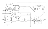
- FIG. 1 a schematically shows an internal combustion engine according to the invention in a first embodiment
- FIG. 1 b schematically shows an internal combustion engine according to the invention in a second embodiment
- FIGS. 2 and 3 show a temporal progression of the load and the determined temperature difference for a leakage-free heat recovery system
- FIGS. 4 and 5 show a temporal progression of the load and the determined temperature difference for a leakage-containing heat recovery system when using the present invention.
- FIGS. 1 and 2 each show an internal combustion engine 1 with exhaust gas flow paths 2 , which are formed by an exhaust gas line 3 and an exhaust gas return line 4 .
- the exhaust gas return line 4 serves for external exhaust gas return between the exhaust system 22 and the intake system 23 of the internal combustion engine 1 .
- An exhaust gas after-treatment device 5 is arranged in the exhaust gas line 3 , which in the exemplary embodiment has a diesel oxidation catalytic converter 6 , a diesel particle filter 7 , an SCR catalytic converter 8 and a barrier catalytic converter 9 .
- An NH 3 -containing additive can be fed via an injection device 10 upstream of the SCR catalytic converter 8 .
- a mixer 11 serves for mixing and evaporation of the injected additive in the exhaust stream.
- Reference numeral 17 denotes a condenser.
- a bypass line 18 is provided which branches off from the exhaust gas line 3 upstream of the evaporator 14 and opens into the exhaust gas line 3 again downstream of the first evaporator 14 .
- Reference numeral 19 denotes a control element, which is formed, for example, by a changeover flap, for switching the exhaust gas flow between the flow path through the evaporator 14 and the bypass line 18 .
- the second evaporator 14 a is integrated into the working medium circuit 13 downstream of the first evaporator 14 .
- the second evaporator 14 a can also be arranged in a second working medium circuit 13 a of the heat recovery system 12 , which has a second pump 15 a , a second expansion machine 16 a and a second condenser 17 a , as shown in FIG. 1 b.
- a first temperature sensor 30 is arranged upstream of the oxidation catalytic converter 6 and a second temperature sensor 31 is arranged downstream of the oxidation catalytic converter 6 .
- the temperature sensors 30 , 31 are connected to a control and/or evaluation unit 21 .
- the exhaust gas temperatures T 30 or T 31 are measured in the exhaust gas line 3 upstream or downstream of the oxidation catalytic converter and a temperature difference ⁇ T is determined on the oxidation catalytic converter 6 between its input 6 a and the output 6 b.
- the oxidation catalytic converter 6 mainly unburnt hydrocarbons (C m H n ) and carbon monoxide (CO) are converted to carbon dioxide and water. During this process, energy is released of the order of the lower calorific values of carbon monoxide and hydrocarbons.
- the lower calorific value of CO is approximately 10.1 MJ/kg
- the lower calorific value of C m H n is, for example, 42 MJ/kg (equivalent to diesel/lubricating oil).
- the released energy is used to heat the oxidation catalytic converter 6 and to heat the exhaust gas stream passing through the oxidation catalytic converter 6 .
- the increase in the exhaust gas temperature during the through-flow of the oxidation catalytic converter 6 is dependent on the concentration of the hydrocarbons and the carbon monoxide at the inlet of the oxidation catalytic converter 6 .
- this temperature difference ⁇ T is subjected to a plausibility check by reducing or stopping the injection quantity of fuel through the fuel injection devices (not shown in closer detail) into the internal combustion engine 1 by using a closed control circuit for example, and it is examined whether a substantial reduction in the measured temperature difference occurs after a defined first waiting time (for example 30 to 60 seconds) has elapsed. Furthermore, if an abnormally high temperature difference ⁇ T is still detected, a conclusion can be drawn on a leakage in the EGR evaporator 14 a.
- the injection of the fuel can be reduced or stopped for carrying out a plausibility check in the motor-braking mode of the internal combustion engine 1 , and it can be examined whether a substantial reduction in the measured temperature difference ⁇ T occurs after a defined second waiting time has elapsed, and if an abnormally high temperature difference ⁇ T is still determined upstream and downstream of the oxidation catalytic converter 6 , a conclusion can be drawn on a leakage in the EGR evaporator 14 a.
- the method according to the invention can be carried out during a stationary operating mode, a transient operating mode or a load-free operating mode of the internal combustion engine 1 .
- a maximum stationary setpoint value for the temperature difference ⁇ T upstream and downstream of the oxidation catalytic converter 6 is defined for at least one defined stationary operating mode of the internal combustion engine 1 .
- the internal combustion engine 1 is operated in this stationary operating mode and the determined temperature difference ⁇ T is compared with the defined stationary setpoint value of the defined stationary operating mode. If the determined temperature difference ⁇ T is greater than the maximum stationary setpoint value of the defined stationary operating mode, a conclusion can be drawn on a leakage in the EGR evaporator 14 a.
- a maximum transient setpoint value for the temperature difference ⁇ T upstream and downstream of the oxidation catalytic converter 6 is defined for at least a defined transient operating mode of the internal combustion engine 1 .
- the internal combustion engine 1 is operated in this transient operating mode and the determined temperature difference ⁇ T is compared with the defined transient setpoint value of the defined transient operating mode.
- a conclusion is drawn on a leakage in the evaporator if the determined temperature difference ⁇ T is greater than the maximum transient setpoint value of the defined transient operating mode.
- the leakage test can also be carried out during at least one load-free operating mode of the internal combustion engine 1 , e.g. idling running, coasting operation or motor-braking operation.
- a minimum value for the temporal reduction of the temperature difference ⁇ T upstream and downstream of the oxidation catalytic converter 6 is defined for at least a defined load-free operating mode of the internal combustion engine 1 .
- the internal combustion engine 1 is operated in this load-free operating mode and a temporal progression of the temperature difference ⁇ T upstream and downstream of the oxidation catalytic converter 6 is determined and compared with the defined minimum value for the temporal reduction in the temperature difference ⁇ T.
- FIGS. 2 and 3 show a temporal progression of the load L and the temperature difference ⁇ T for a leakage-free heat recovery system 12 during a changeover of the internal combustion engine 1 to the motor-braking mode.
- the injection of the fuel is substantially reduced or stopped during the motor-braking operation. It can clearly be seen that the determined temperature difference ⁇ T drastically decreases, thus there is no leakage.
- FIGS. 4 and 5 show a changeover to motor-braking operation when there is a leakage in the EGR evaporator 14 a .
- the line b) shows the case that no change occurs in the temperature difference ⁇ T.
- the reduction in the temperature difference ⁇ T is substantially lower than expected, i.e. the minimum value indicated by line d) for the temporal reduction of the temperature difference ⁇ T is not reached.
- a leakage of the EGR evaporator 14 a can be clearly concluded and a corresponding leakage warning can be output to the driver.
- first 30 and second temperature sensors 31 arranged as a standard in the exhaust gas line 3 can be used in order to enable reliable leakage tests to be carried out.
Landscapes
- Engineering & Computer Science (AREA)
- Chemical & Material Sciences (AREA)
- Combustion & Propulsion (AREA)
- Mechanical Engineering (AREA)
- General Engineering & Computer Science (AREA)
- Chemical Kinetics & Catalysis (AREA)
- Physics & Mathematics (AREA)
- Life Sciences & Earth Sciences (AREA)
- Sustainable Development (AREA)
- Sustainable Energy (AREA)
- Thermal Sciences (AREA)
- Health & Medical Sciences (AREA)
- Toxicology (AREA)
- Materials Engineering (AREA)
- General Physics & Mathematics (AREA)
- Exhaust Gas After Treatment (AREA)
Applications Claiming Priority (2)
| Application Number | Priority Date | Filing Date | Title |
|---|---|---|---|
| ATA50641/2016 | 2016-07-18 | ||
| ATA50641/2016A AT518521B1 (de) | 2016-07-18 | 2016-07-18 | Verfahren zur erkennung einer undichten stelle in einem wärmerückgewinnungssystem |
Publications (2)
| Publication Number | Publication Date |
|---|---|
| US20180016901A1 US20180016901A1 (en) | 2018-01-18 |
| US10024159B2 true US10024159B2 (en) | 2018-07-17 |
Family
ID=60268090
Family Applications (1)
| Application Number | Title | Priority Date | Filing Date |
|---|---|---|---|
| US15/652,997 Active US10024159B2 (en) | 2016-07-18 | 2017-07-18 | Method for detecting a leaking point in a heat recovery system |
Country Status (2)
| Country | Link |
|---|---|
| US (1) | US10024159B2 (de) |
| AT (1) | AT518521B1 (de) |
Cited By (1)
| Publication number | Priority date | Publication date | Assignee | Title |
|---|---|---|---|---|
| US10677678B2 (en) * | 2015-08-28 | 2020-06-09 | Avl List Gmbh | Method for detecting an unsealed location in a heat recovery system of an internal combustion engine |
Citations (12)
| Publication number | Priority date | Publication date | Assignee | Title |
|---|---|---|---|---|
| US6526358B1 (en) | 1999-10-01 | 2003-02-25 | General Electric Company | Model-based detection of leaks and blockages in fluid handling systems |
| US20050150212A1 (en) | 2004-01-14 | 2005-07-14 | Andreas Pfaeffle | Method and controller for exhaust gas temperature control |
| US20080022677A1 (en) * | 2006-07-28 | 2008-01-31 | David Barbe | System and Method for Diagnostic of Low Pressure Exhaust Gas Recirculation System and Adapting of Measurement Devices |
| US20100146943A1 (en) | 2008-12-11 | 2010-06-17 | Denso Corporation | Exhaust heat recovery device |
| JP2010156314A (ja) | 2009-01-05 | 2010-07-15 | Toyota Motor Corp | 廃熱回収装置、及びエンジン |
| US20140050623A1 (en) * | 2011-04-12 | 2014-02-20 | Toyota Jidosha Kabushiki Kaisha | Apparatus for detecting deterioration of nox selective reduction catalyst |
| US20140109554A1 (en) * | 2011-05-06 | 2014-04-24 | Daimler Ag | Method For Operating a Motor Vehicle Diesel Engine |
| DE102012221153A1 (de) | 2012-11-20 | 2014-06-05 | Robert Bosch Gmbh | Verfahren zur Überwachung eines Systems zur Energierückgewinnung aus einem Abwärmestrom einer Brennkraftmaschine |
| US8783029B2 (en) * | 2011-01-12 | 2014-07-22 | Ford Global Technologies, Llc | Supercharged internal combustion engine and method for operating an internal combustion engine of said type |
| US20150040862A1 (en) * | 2013-08-09 | 2015-02-12 | Hyundai Motor Company | Method of monitoring egr system |
| WO2016087096A1 (de) | 2014-12-05 | 2016-06-09 | Robert Bosch Gmbh | Verfahren zum betrieb einer abwärmenutzungsanordnung |
| US9458799B2 (en) * | 2010-11-04 | 2016-10-04 | Daimler Ag | Method for operating motor vehicle internal combustion engine |
-
2016
- 2016-07-18 AT ATA50641/2016A patent/AT518521B1/de not_active IP Right Cessation
-
2017
- 2017-07-18 US US15/652,997 patent/US10024159B2/en active Active
Patent Citations (12)
| Publication number | Priority date | Publication date | Assignee | Title |
|---|---|---|---|---|
| US6526358B1 (en) | 1999-10-01 | 2003-02-25 | General Electric Company | Model-based detection of leaks and blockages in fluid handling systems |
| US20050150212A1 (en) | 2004-01-14 | 2005-07-14 | Andreas Pfaeffle | Method and controller for exhaust gas temperature control |
| US20080022677A1 (en) * | 2006-07-28 | 2008-01-31 | David Barbe | System and Method for Diagnostic of Low Pressure Exhaust Gas Recirculation System and Adapting of Measurement Devices |
| US20100146943A1 (en) | 2008-12-11 | 2010-06-17 | Denso Corporation | Exhaust heat recovery device |
| JP2010156314A (ja) | 2009-01-05 | 2010-07-15 | Toyota Motor Corp | 廃熱回収装置、及びエンジン |
| US9458799B2 (en) * | 2010-11-04 | 2016-10-04 | Daimler Ag | Method for operating motor vehicle internal combustion engine |
| US8783029B2 (en) * | 2011-01-12 | 2014-07-22 | Ford Global Technologies, Llc | Supercharged internal combustion engine and method for operating an internal combustion engine of said type |
| US20140050623A1 (en) * | 2011-04-12 | 2014-02-20 | Toyota Jidosha Kabushiki Kaisha | Apparatus for detecting deterioration of nox selective reduction catalyst |
| US20140109554A1 (en) * | 2011-05-06 | 2014-04-24 | Daimler Ag | Method For Operating a Motor Vehicle Diesel Engine |
| DE102012221153A1 (de) | 2012-11-20 | 2014-06-05 | Robert Bosch Gmbh | Verfahren zur Überwachung eines Systems zur Energierückgewinnung aus einem Abwärmestrom einer Brennkraftmaschine |
| US20150040862A1 (en) * | 2013-08-09 | 2015-02-12 | Hyundai Motor Company | Method of monitoring egr system |
| WO2016087096A1 (de) | 2014-12-05 | 2016-06-09 | Robert Bosch Gmbh | Verfahren zum betrieb einer abwärmenutzungsanordnung |
Non-Patent Citations (2)
| Title |
|---|
| English Abstract of DE 102012221153. |
| English Abstract of JP 2010156314. |
Cited By (1)
| Publication number | Priority date | Publication date | Assignee | Title |
|---|---|---|---|---|
| US10677678B2 (en) * | 2015-08-28 | 2020-06-09 | Avl List Gmbh | Method for detecting an unsealed location in a heat recovery system of an internal combustion engine |
Also Published As
| Publication number | Publication date |
|---|---|
| AT518521B1 (de) | 2017-11-15 |
| US20180016901A1 (en) | 2018-01-18 |
| AT518521A4 (de) | 2017-11-15 |
Similar Documents
| Publication | Publication Date | Title |
|---|---|---|
| CN106168151B (zh) | 诊断内燃发动机后处理系统中压力传感器故障的控制系统 | |
| US8649961B2 (en) | Method of diagnosing several systems and components by cycling the EGR valve | |
| US7841173B2 (en) | Conservation of energy catalyst monitor | |
| CN103249926B (zh) | 恒温器故障判定装置 | |
| US8997726B2 (en) | Method for diagnosing a liquid-cooled exhaust manifold of an internal combustion engine | |
| RU2677775C2 (ru) | Система обнаружения утечки во всасывающем трубопроводе двигателя внутреннего сгорания | |
| JP2010539390A (ja) | 排気ガス再循環システムの熱交換器のバイパスフラップを診断する方法 | |
| KR101836285B1 (ko) | 센서의 고장 진단 장치 및 방법 | |
| JP2013217233A (ja) | 尿素水ヒーティングバルブの診断方法及びその装置 | |
| JP5071242B2 (ja) | ターボ過給機付きエンジンの排気温度検出装置の劣化診断装置 | |
| US20090076716A1 (en) | Characteristic number method for engine real-time diagnostics application | |
| US20160169168A1 (en) | Exhaust system state detection device | |
| US10024159B2 (en) | Method for detecting a leaking point in a heat recovery system | |
| US11125146B2 (en) | Systems and methods for diagnosing a thermostat | |
| US8342015B2 (en) | Method for diagnosing the exchanger bypass flap in an exhaust gas recirculation circuit | |
| JP2008309134A (ja) | Egrクーラの水漏れ検出装置 | |
| US10677678B2 (en) | Method for detecting an unsealed location in a heat recovery system of an internal combustion engine | |
| US10815834B2 (en) | Method for detecting an unsealed location in a heat recovery system | |
| JP5738576B2 (ja) | 水温センサ故障判定装置 | |
| JP6111983B2 (ja) | 吸気制御装置 | |
| US9016062B2 (en) | Checking an exhaust gas flap | |
| JP4605510B2 (ja) | 内燃機関の排気ガス還流装置 | |
| US11608801B2 (en) | Engine control device | |
| CN119308745A (zh) | 用于运行内燃机的排气设备的方法、排气设备以及内燃机 |
Legal Events
| Date | Code | Title | Description |
|---|---|---|---|
| AS | Assignment |
Owner name: AVL LIST GMBH, AUSTRIA Free format text: ASSIGNMENT OF ASSIGNORS INTEREST;ASSIGNORS:GLENSVIG, MICHAEL;THALER, MARKUS;MAHLER, SUSANNE;REEL/FRAME:045746/0403 Effective date: 20180417 Owner name: FPT INDUSTRIAL S.P.A., ITALY Free format text: ASSIGNMENT OF ASSIGNORS INTEREST;ASSIGNORS:GLENSVIG, MICHAEL;THALER, MARKUS;MAHLER, SUSANNE;REEL/FRAME:045746/0403 Effective date: 20180417 Owner name: IVECO S.P.A., ITALY Free format text: ASSIGNMENT OF ASSIGNORS INTEREST;ASSIGNORS:GLENSVIG, MICHAEL;THALER, MARKUS;MAHLER, SUSANNE;REEL/FRAME:045746/0403 Effective date: 20180417 |
|
| STCF | Information on status: patent grant |
Free format text: PATENTED CASE |
|
| CC | Certificate of correction | ||
| MAFP | Maintenance fee payment |
Free format text: PAYMENT OF MAINTENANCE FEE, 4TH YEAR, LARGE ENTITY (ORIGINAL EVENT CODE: M1551); ENTITY STATUS OF PATENT OWNER: LARGE ENTITY Year of fee payment: 4 |
|
| FEPP | Fee payment procedure |
Free format text: MAINTENANCE FEE REMINDER MAILED (ORIGINAL EVENT CODE: REM.); ENTITY STATUS OF PATENT OWNER: LARGE ENTITY |