US10034097B2 - MEMS acoustic transducer, and acoustic transducer assembly having a stopper mechanism - Google Patents
MEMS acoustic transducer, and acoustic transducer assembly having a stopper mechanism Download PDFInfo
- Publication number
- US10034097B2 US10034097B2 US15/311,129 US201515311129A US10034097B2 US 10034097 B2 US10034097 B2 US 10034097B2 US 201515311129 A US201515311129 A US 201515311129A US 10034097 B2 US10034097 B2 US 10034097B2
- Authority
- US
- United States
- Prior art keywords
- membrane
- mems
- reinforcing element
- sound transducer
- end stop
- Prior art date
- Legal status (The legal status is an assumption and is not a legal conclusion. Google has not performed a legal analysis and makes no representation as to the accuracy of the status listed.)
- Active
Links
Images


Classifications
-
- H—ELECTRICITY
- H04—ELECTRIC COMMUNICATION TECHNIQUE
- H04R—LOUDSPEAKERS, MICROPHONES, GRAMOPHONE PICK-UPS OR LIKE ACOUSTIC ELECTROMECHANICAL TRANSDUCERS; ELECTRIC HEARING AIDS; PUBLIC ADDRESS SYSTEMS
- H04R19/00—Electrostatic transducers
- H04R19/005—Electrostatic transducers using semiconductor materials
-
- B—PERFORMING OPERATIONS; TRANSPORTING
- B81—MICROSTRUCTURAL TECHNOLOGY
- B81B—MICROSTRUCTURAL DEVICES OR SYSTEMS, e.g. MICROMECHANICAL DEVICES
- B81B3/00—Devices comprising flexible or deformable elements, e.g. comprising elastic tongues or membranes
- B81B3/0018—Structures acting upon the moving or flexible element for transforming energy into mechanical movement or vice versa, i.e. actuators, sensors, generators
- B81B3/0021—Transducers for transforming electrical into mechanical energy or vice versa
-
- B—PERFORMING OPERATIONS; TRANSPORTING
- B81—MICROSTRUCTURAL TECHNOLOGY
- B81B—MICROSTRUCTURAL DEVICES OR SYSTEMS, e.g. MICROMECHANICAL DEVICES
- B81B3/00—Devices comprising flexible or deformable elements, e.g. comprising elastic tongues or membranes
- B81B3/0035—Constitution or structural means for controlling the movement of the flexible or deformable elements
- B81B3/0037—For increasing stroke, i.e. achieve large displacement of actuated parts
-
- H—ELECTRICITY
- H04—ELECTRIC COMMUNICATION TECHNIQUE
- H04R—LOUDSPEAKERS, MICROPHONES, GRAMOPHONE PICK-UPS OR LIKE ACOUSTIC ELECTROMECHANICAL TRANSDUCERS; ELECTRIC HEARING AIDS; PUBLIC ADDRESS SYSTEMS
- H04R17/00—Piezoelectric transducers; Electrostrictive transducers
-
- H—ELECTRICITY
- H04—ELECTRIC COMMUNICATION TECHNIQUE
- H04R—LOUDSPEAKERS, MICROPHONES, GRAMOPHONE PICK-UPS OR LIKE ACOUSTIC ELECTROMECHANICAL TRANSDUCERS; ELECTRIC HEARING AIDS; PUBLIC ADDRESS SYSTEMS
- H04R17/00—Piezoelectric transducers; Electrostrictive transducers
- H04R17/005—Piezoelectric transducers; Electrostrictive transducers using a piezoelectric polymer
-
- H—ELECTRICITY
- H04—ELECTRIC COMMUNICATION TECHNIQUE
- H04R—LOUDSPEAKERS, MICROPHONES, GRAMOPHONE PICK-UPS OR LIKE ACOUSTIC ELECTROMECHANICAL TRANSDUCERS; ELECTRIC HEARING AIDS; PUBLIC ADDRESS SYSTEMS
- H04R23/00—Transducers other than those covered by groups H04R9/00 - H04R21/00
- H04R23/02—Transducers using more than one principle simultaneously
-
- H—ELECTRICITY
- H04—ELECTRIC COMMUNICATION TECHNIQUE
- H04R—LOUDSPEAKERS, MICROPHONES, GRAMOPHONE PICK-UPS OR LIKE ACOUSTIC ELECTROMECHANICAL TRANSDUCERS; ELECTRIC HEARING AIDS; PUBLIC ADDRESS SYSTEMS
- H04R7/00—Diaphragms for electromechanical transducers; Cones
- H04R7/16—Mounting or tensioning of diaphragms or cones
- H04R7/18—Mounting or tensioning of diaphragms or cones at the periphery
-
- B—PERFORMING OPERATIONS; TRANSPORTING
- B81—MICROSTRUCTURAL TECHNOLOGY
- B81B—MICROSTRUCTURAL DEVICES OR SYSTEMS, e.g. MICROMECHANICAL DEVICES
- B81B2201/00—Specific applications of microelectromechanical systems
- B81B2201/02—Sensors
- B81B2201/0257—Microphones or microspeakers
-
- B—PERFORMING OPERATIONS; TRANSPORTING
- B81—MICROSTRUCTURAL TECHNOLOGY
- B81B—MICROSTRUCTURAL DEVICES OR SYSTEMS, e.g. MICROMECHANICAL DEVICES
- B81B2203/00—Basic microelectromechanical structures
- B81B2203/01—Suspended structures, i.e. structures allowing a movement
- B81B2203/0127—Diaphragms, i.e. structures separating two media that can control the passage from one medium to another; Membranes, i.e. diaphragms with filtering function
-
- B—PERFORMING OPERATIONS; TRANSPORTING
- B81—MICROSTRUCTURAL TECHNOLOGY
- B81B—MICROSTRUCTURAL DEVICES OR SYSTEMS, e.g. MICROMECHANICAL DEVICES
- B81B2203/00—Basic microelectromechanical structures
- B81B2203/03—Static structures
- B81B2203/0315—Cavities
-
- H—ELECTRICITY
- H04—ELECTRIC COMMUNICATION TECHNIQUE
- H04R—LOUDSPEAKERS, MICROPHONES, GRAMOPHONE PICK-UPS OR LIKE ACOUSTIC ELECTROMECHANICAL TRANSDUCERS; ELECTRIC HEARING AIDS; PUBLIC ADDRESS SYSTEMS
- H04R2201/00—Details of transducers, loudspeakers or microphones covered by H04R1/00 but not provided for in any of its subgroups
- H04R2201/003—Mems transducers or their use
Definitions
- This invention relates to a MEMS sound transducer for generating and/or detecting sound waves in the audible wavelength spectrum, along with a sound transducer arrangement with such a MEMS sound transducer.
- MEMS microelectromechanical systems
- a MEMS sound transducer for sound generation or a MEMS loudspeaker is known, for example, from DE 10 2012 220 819 A1 Sound is generated by a swivel-mounted membrane of the MEMS loudspeaker.
- Such sound transducer arrangements are specifically constructed according to the acoustic and other requirements of the respective application area, and consist of a multiple number of different elements.
- Such sound transducer arrangements can be very small in size, and are therefore installed as loudspeakers and/or microphones, for example, in hearing aids, in-ear headphones, mobile telephones, tablet computers and other electronic devices that offer little installation space.
- a MEMS sound transducer for detecting sound waves or a MEMS microphone is known from WO 2015/017979 A1 and U.S. Pat. No. 9,462,389, which is hereby incorporated herein by this reference for all purposes.
- This MEMS sound transducer is characterized by a stopper mechanism that protects the sensitive membrane from damages that could occur, for example, through the excessive movement of the membrane due to sound pressure or impact.
- the complex structure, which can be manufactured only with great expense, of this stopper mechanism which comprises a plate with holes and T-shaped stopper elements, is disadvantageous.
- the plate is arranged in a manner spaced at a distance from the membrane and features a plurality of holes, through which the stopper elements extend with their lower free ends. With the other ends, the stopper elements are fastened to the membrane.
- the task of this invention is to provide a MEMS sound transducer with an improved stopper mechanism that is easy to design and manufacture.
- a MEMS sound transducer for generating and/or detecting sound waves in the audible wavelength spectrum, with a membrane carrier, a membrane and a stopper mechanism is proposed.
- the membrane is connected in its edge area to the membrane carrier, and may vibrate along the z-axis with respect to the membrane carrier.
- the stopper mechanism is formed to limit the vibrations of the membrane in at least one direction.
- the stopper mechanism includes at least one reinforcing element that is arranged on one side of the membrane.
- the stopper mechanism comprises an end stop opposite to the reinforcing element, and the end stop is spaced at a distance from the membrane when the membrane is disposed in a neutral position of the membrane and against which the reinforcing element abuts at a maximum deflection of the membrane.
- a stopper mechanism which is simple in design and thus can be manufactured simply and cost-effectively.
- no T-shaped stopper elements need to be guided through holes in a plate and connected to the membrane.
- the membrane is formed with a reinforcing element that works together with an opposing stop.
- the MEMS sound transducer comprises a MEMS actuator, which in particular has a carrier substrate, and which works together with the membrane, in order to convert electrical signals into acoustically perceptible sound waves.
- a MEMS actuator which in particular has a carrier substrate, and which works together with the membrane, in order to convert electrical signals into acoustically perceptible sound waves.
- the carrier substrate is preferably made of silicon.
- the end stop is at least partially formed on the MEMS actuator, in particular on the carrier substrate of the MEMS actuator, on a housing part and/or on a circuit board.
- the reinforcing element is fastened to the membrane on a side turned towards the MEMS actuator. As a result, upon its abutment, the membrane is protected against the end stop by means of the reinforcing element.
- the front surface of the carrier substrate of the MEMS actuator turned towards the membrane is formed as an end stop.
- the MEMS actuator in particular on a side of the carrier substrate turned away from the membrane, features an actuator structure.
- the actuator structure is preferably formed from a piezoelectric layer.
- the edge area of the membrane is fastened in a fastening area of the membrane carrier spaced at a distance from the MEMS actuator, in particular from the carrier substrate, preferably in the x-, y- and/or z-direction.
- At least one housing part and/or one circuit board forms the membrane carrier, whereas the membrane is preferably fastened between two such components.
- the membrane features an outer elastic area, in particular formed as a bulge. This is preferably arranged adjacent to the edge area.
- the membrane features an inner reinforced area, in which the reinforcing element is arranged.
- the elastic area allows the membrane to vibrate with respect to the membrane carrier.
- the inner reinforced area of the membrane, with the reinforcing element can vibrate with respect to the outer edge area of the membrane and/or its fastening area.
- the reinforced area and/or the reinforcing element is arranged in a manner adjacent (in particular, directly adjacent) to the elastic area.
- the reinforcing element can be formed from a plastic, a metal and/or a fiber composite material. It is also advantageous if the reinforcing element is formed with a plate-shaped design, is glued to the membrane, in particular made of silicone, and/or extends over the entire reinforced area. In its reinforced area or through the reinforcing element, the membrane has an increased stiffness and thus better acoustic properties, in particular with regard to achievable loudness, frequency range and/or signal consistency.
- the reinforcing element features an end stop surface corresponding to the end stop.
- the end stop surface is preferably formed as a closed frame.
- the reinforcing element features a coupling surface, which is preferably arranged in the interior of the frame-shaped end stop surface and/or in the area of which the reinforcing element is connected to the actuator structure, in particular indirectly through a coupling element.
- the end stop surface and the coupling surface are spaced at a distance from each other in the z-direction and/or are connected to each other through an intermediate area (in particular, a funnel-shaped intermediate area) of the reinforcing element.
- an intermediate area in particular, a funnel-shaped intermediate area
- the total area of the membrane is advantageously enlarged without the membrane having a larger diameter, by which installation space and material can be saved—with a simultaneous improvement in the acoustic properties of the membrane.
- the carrier substrate and the coupling element are produced from the same substrate, in particular a silicon substrate, and in particular feature the same thickness.
- the stopper mechanism comprises a second end stop, which limits the vibrations of the membrane along the z-axis in a second direction opposite to the first direction, whereas the second end stop preferably is arranged in a sound-conducting channel formed by a housing part.
- the two end stops are arranged opposite to each other, and/or the reinforcing element is arranged between such end stops and is spaced at a distance from such end stops.
- the sound transducer arrangement comprises, in addition to a MEMS sound transducer, a circuit board that features a fully embedded ASIC and/or a recess extending through the circuit board, whereas, preferably, at a first opening of the recess, a MEMS actuator is arranged and/or, at a second opening of the recess, a housing part is arranged, in order to form a closed cavity.
- FIG. 1 a first embodiment of the sound transducer arrangement and of the MEMS sound transducer in a view partially in perspective and partially sectional and including an enlarged view of a portion thereof,
- FIG. 2 the first embodiment of the sound transducer arrangement and the MEMS sound transducer in a schematic lateral sectional view
- FIG. 3 the first embodiment of the sound transducer arrangement and the MEMS sound transducer with a membrane that has been swung out in a first direction, in a schematic lateral sectional view.
- FIG. 4 the first embodiment of the sound transducer arrangement and the MEMS sound transducer with a membrane that has been swung out in a second direction, in a schematic lateral sectional view
- FIG. 5 a second embodiment of the sound transducer arrangement and the MEMS sound transducer in a view partially in perspective and partially sectional
- FIG. 6 the second embodiment of the sound transducer arrangement and the MEMS sound transducer in a schematic lateral sectional view
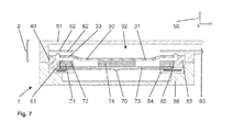
- FIG. 7 a third embodiment of the sound transducer arrangement and the MEMS sound transducer in a schematic lateral sectional view.
- FIGS. 1 to 4 show a first embodiment of a sound transducer arrangement 1 with a MEMS sound transducer 2 in various views in which the three orthogonal dimensions are indicated by the letters x, y and z in FIGS. 2, 3 and 4 for example.
- the length dimension y of the transducer arrangement 1 extends along the direction of the arrow pointing to the letter y, while the depth dimension z of the transducer arrangement 1 extends along the direction of the arrow pointing to the letter z.
- the width dimension x of the transducer arrangement 1 extends along the direction that is normal to the plane of the FIGS. 2, 3 and 4 for example.
- the MEMS sound transducer 2 is formed for generating and/or detecting sound waves in the audible wavelength spectrum.
- the membrane 30 has a membrane 30 and a membrane carrier 40 .
- the membrane 30 is connected to the membrane carrier 40 in the edge area 37 of the membrane 30 , and is able to vibrate along the z-axis 50 with respect to the membrane carrier 40 .
- the z-axis 50 runs essentially perpendicular to the membrane 30 .
- the MEMS sound transducer 2 also features a stopper mechanism 60 ( FIG. 1 ), which is formed to limit the vibrations of the membrane 30 in at least one direction schematically represented by the arrow in FIG. 3 designated 51 .
- the stopper mechanism 60 features a reinforcing element 31 , which is arranged on one side of the membrane 30 , shown here in FIGS. 1-4 on its underside.
- the stopper mechanism 60 includes an end stop 61 disposed to block movement of the reinforcing element 31 .
- the end stop 61 is spaced at a distance from the membrane 30 in a neutral position of the membrane 30 , as shown in FIGS. 1 and 2 , and against which at least a portion of the reinforcing element 31 abuts at a maximum deflection of the membrane 30 in the direction 51 , as shown in FIG. 3 .
- the stopper mechanism 60 also comprises a second end stop 62 , which limits the vibrations of the membrane 30 along the z-axis 50 in a second direction 52 (schematically shown in FIG. 4 ) opposite to the first direction 51 (schematically shown in FIG. 3 ).
- the second end stop 62 is also spaced at a distance from the membrane 30 in a neutral position of the membrane 30 , as shown in FIGS. 1 and 2 , whereas a portion of the reinforcing element 31 is restrained by the second end stop 62 at a maximum deflection of the membrane 30 in the second direction 52 , as shown in FIG. 4 .
- the membrane 30 is located between the second end stop 62 and the reinforcing element 31 .
- the membrane 30 according to FIG. 3 is swung downwards or deflected downwards, to the extent that the reinforcing element 31 abuts at the first end stop 61 , while, according to FIG. 4 , the membrane 30 is swung upwards or deflected upwards, to the extent that the reinforcing element 31 is restrained at the second end stop 62 of the stopper mechanism 60 .
- the two end stops 61 , 62 are arranged in a manner opposite to each other, whereas the reinforcing element 31 is arranged between such two end stops 61 , 62 and is spaced at a distance from them.
- the second end stop 62 is arranged on an upper housing part 81 , which is arranged above the membrane 30 , and in particular in a sound-conducting channel 92 formed by the upper housing part 81 .
- the first end stop 61 is arranged on a carrier substrate 71 of a MEMS actuator 70 or is formed by one side of the carrier substrate 71 .
- This MEMS actuator 70 is arranged below the membrane 30 and/or is essentially parallel to the membrane 30 .
- the MEMS actuator 70 works together with the membrane 30 to convert electrical signals into acoustically perceptible sound waves or vice versa.
- the MEMS actuator 70 comprises an actuator structure 73 that is preferably designed to be piezoelectric.
- the actuator structure 73 is arranged on a side of the carrier substrate 71 facing away from the membrane 30 .
- the front surface 72 of the carrier substrate 71 of the MEMS actuator 70 facing towards the membrane 30 is formed as an end stop 61 .
- the first end stop 61 could also be formed on a housing part, such as the middle housing part 83 and/or on a circuit board, such as the circuit board 84 .
- the reinforcing element 31 is fastened to the membrane 30 on the the present case, the reinforcing element 31 is fastened to the membrane 30 on the side facing towards the MEMS actuator 70 .
- the reinforcing element 31 or an additional reinforcing element could, in principle, also be fastened to the membrane 30 on the side facing away from the MEMS actuator 70 .
- the reinforcing element 31 features surrounding the outer perimeter region thereof an end stop section 33 that is disposed between and free to abut alternately with the end stops 61 , 62 .
- the sound transducer arrangement 1 also includes a circuit board 84 and a lower housing part 89 .
- An ASIC 85 is fully embedded in the circuit board 84 .
- other passive components such as electrical resistors and/or I/O contacts, may be embedded in and/or arranged on the circuit board.
- the circuit board 84 features a recess 86 which extends fully through the depth of the circuit board in the z dimension and has two openings 87 , 88 , one opening at each of the opposite surfaces of the circuit board 84 .
- the MEMS actuator 70 is arranged at the first opening 87 of the recess 86 .
- the lower housing part 89 is arranged at the second opening 88 of the recess 86 to form a closed cavity 90 .
- the circuit board 84 is arranged between the MEMS actuator 70 and the lower housing part 89 .
- the MEMS sound transducer 2 and in particular the MEMS actuator 70 , is connected to the ASIC 85 with electrical contacts that are not further shown in the figures.
- the MEMS sound transducer 2 can thus be controlled or operated by means of ASIC 85 .
- the MEMS sound transducer 2 if it is to function as a loudspeaker, it can be excited by means of the ASIC 85 in such a manner that, through the MEMS actuator 70 , the membrane 30 for generating sound energy is vibrated with respect to the membrane carrier 40 .
- the term “cavity” is to be understood as an empty space by means of which the sound pressure of the MEMS sound transducer can be reinforced.
- the sound transducer arrangement 1 can be formed in a manner that saves installation space to a high degree, but with a relatively large acoustically effective cavity volume, since the empty space provided by the lower housing part 89 for forming the cavity 90 can now turn out to be smaller.
- the housing parts 81 , 83 , and in particular the lower housing part 89 preferably feature a material that is different from the circuit board 84 .
- at least one of the housing parts 81 could also be a component of the circuit board 84 .
- the sound transducer arrangement 1 has an essentially rectangular basic shape, and is thus simple and cost-effective to manufacture, and is suitable for numerous applications.
- the sound transducer arrangement 1 is also constructed in a sandwich-like manner; that is, the lower housing part 89 , the circuit board 84 and the MEMS sound transducer 2 are arranged in a manner stacked on top of each other.
- the MEMS sound transducer 2 , the circuit board 84 and the lower housing part 89 a il have the same outer dimensions of length and width.
- the sound transducer arrangement 1 can, in principle, also feature a basic shape (in particular, a round basic shape).
- the membrane 30 which consists, in particular, of silicone, is fastened in its edge area 37 in the fastening area 41 of the membrane carrier 40 as shown in FIG. 2 , whereas the fastening area 41 is arranged in a manner spaced at a distance from the MEMS actuator 70 and its carrier substrate 71 in the x-, y- and z-directions.
- the membrane carrier 40 is formed by the upper housing part 81 and the middle housing part 83 , whereas the fastening area 41 is located between the two housing parts 81 , 83 , and the edge area 37 of the membrane 30 is thus fastened between such two housing parts 81 , 83 .
- the membrane carrier 40 is formed with frame-like design and surrounds the membrane 30 . Unlike that shown here in FIG. 2 , however, the membrane carrier 40 could also be at least partially formed by a circuit board, such as the circuit board 84 .
- the membrane 30 Adjacent to its edge area 37 , the membrane 30 features an outer elastic area 38 shown in FIGS. 2, 3 and 4 , formed in the present case in particular as a bulge 39 , and an inner reinforced area 32 , in which the reinforcing element 31 is arranged. At this, the reinforced area 32 or the reinforcing element 31 , as the case may be, is arranged immediately adjacent to the elastic area 38 .
- the elastic area 38 allows the membrane 30 to vibrate with respect to the membrane carrier 40 , and in particular the inner-reinforced area 32 with respect to the outer edge area 37 .
- the reinforcing element 31 is made of a metal and/or is formed with a plate-shaped design, whereas, as in the present case, it preferably extends over the entire reinforced area 32 and is glued to the membrane 30 .
- the end stop section 33 of the reinforcing element 31 that is configured and disposed to interact alternately with the stops 61 , 62 is formed with frame-like design and is arranged immediately adjacent to the membrane's elastic area 38 , which is likewise formed with frame-like design.
- first end stop 61 and the second end stop 62 are formed with frame-like design, in this example corresponding to the end stop section 33 of the reinforcing element 31 .
- the carrier substrate 71 which provides the first end stop 61 on its front surface 72 , surrounds the actuator structure 73 in a frame-like manner, while the upper housing part 81 features a projection 82 , which surrounds the acoustic inlet/outlet opening 93 of the sound-conducting channel 92 in a frame-like manner and provides the second end stop 62 .
- the reinforcing element 31 of the membrane 30 features a coupling section 35 as schematically shown in FIG. 4 .
- the end stop section 33 and the coupling section 35 are spaced at a distance from each other in the z-direction and are connected to each other through an intermediate section 34 of the reinforcing element 31 , which in this case is funnel-shaped in this case leading from the end stop section 33 to the coupling section 35 . Since the reinforcing element 31 is glued to the membrane 30 , the membrane 30 accordingly has a funnel-like shape.
- the reinforcing element 31 is connected to the actuator structure 73 of the MEMS actuator 70 through a coupling element 74 .
- the carrier substrate 71 and the coupling element 74 are produced from the same substrate, in particular a silicon substrate. They also feature the same thickness as measured in the z direction. Unlike the one shown here, alternatively or in addition to the coupling element 74 , an adapter element for connecting to the actuator structure 73 can be used.
- FIGS. 5 to 7 show additional embodiments of the sound transducer arrangement 1 and the MEMS sound transducer 2 , whereas, essentially, only the differences with respect to the first embodiment already described are discussed below.
- the same reference signs are used for characteristics that are identical and/or at least comparable when compared to the first embodiment shown in FIGS. 1 to 4 , in terms of their design and mode of action. To the extent that such characteristics are not explained once again in detail, their design and mode of action correspond to the characteristics described above.
- the differences described below can be combined with the characteristics of the respective preceding and subsequent embodiments.
- FIGS. 5 and 6 show a second embodiment of the sound transducer arrangement 1 and the MEMS sound transducer 2 in different views.
- the upper housing part 81 is to be mentioned as a major difference from the first embodiment shown in FIGS. 1 to 4 .
- the upper housing part 81 forms a sound-conducting channel 92 with an acoustic inlet/outlet opening 93 , which is arranged laterally on the outer surface of the MEMS sound transducer 2 or the sound transducer arrangement 1 , as the case may be.
- the housing part 81 provides, in particular, additional protection for the membrane 30 , since it provides a cover against the environment.
- no second end stop is provided in this embodiment; that is, no end stop for the reinforcing element 31 of the membrane 30 is arranged on the upper housing part 81 .
- the upper housing part 81 is not a component of the membrane carrier 40 .
- the membrane carrier 40 is formed solely by the middle housing part 83 , such that the membrane 30 is fastened solely to the middle housing part 83 .
- the upper and lower housing parts 81 , 89 have a larger outer diameter in comparison to the first embodiment, by which the base surface of the sound transducer arrangement 1 is enlarged.
- the upper housing part 81 is not arranged on the middle housing part 83 , but on the lower housing part 89 , and is connected to this, such that such two housing parts 81 , 89 together form a housing that surrounds the remaining components of the sound transducer arrangement 1 or the MEMS sound transducer 2 , as the case may be.
- FIG. 7 shows a third embodiment of the sound transducer arrangement 1 and the MEMS sound transducer 2 .
- the upper housing part 81 within the sound-conducting channel 92 features a projection 82 , which is arranged above the membrane 30 , and above the reinforcing element 31 of the membrane 30 and forms the second end stop 62 .
Landscapes
- Engineering & Computer Science (AREA)
- Physics & Mathematics (AREA)
- Acoustics & Sound (AREA)
- Signal Processing (AREA)
- Microelectronics & Electronic Packaging (AREA)
- Computer Hardware Design (AREA)
- Multimedia (AREA)
- Chemical & Material Sciences (AREA)
- Analytical Chemistry (AREA)
- Piezo-Electric Transducers For Audible Bands (AREA)
- Electrostatic, Electromagnetic, Magneto- Strictive, And Variable-Resistance Transducers (AREA)
- Micromachines (AREA)
- Audible-Bandwidth Dynamoelectric Transducers Other Than Pickups (AREA)
Applications Claiming Priority (4)
| Application Number | Priority Date | Filing Date | Title |
|---|---|---|---|
| DE102014106753 | 2014-05-14 | ||
| DE102014106753.3 | 2014-05-14 | ||
| DE102014106753.3A DE102014106753B4 (de) | 2014-05-14 | 2014-05-14 | MEMS-Lautsprecher mit Aktuatorstruktur und davon beabstandeter Membran |
| PCT/EP2015/060658 WO2015173333A1 (de) | 2014-05-14 | 2015-05-13 | Mems-schallwandler sowie schallwandleranordnung mit stopper-mechanismus |
Publications (2)
| Publication Number | Publication Date |
|---|---|
| US20170085994A1 US20170085994A1 (en) | 2017-03-23 |
| US10034097B2 true US10034097B2 (en) | 2018-07-24 |
Family
ID=53177488
Family Applications (2)
| Application Number | Title | Priority Date | Filing Date |
|---|---|---|---|
| US15/311,129 Active US10034097B2 (en) | 2014-05-14 | 2015-05-13 | MEMS acoustic transducer, and acoustic transducer assembly having a stopper mechanism |
| US15/311,127 Active US9980051B2 (en) | 2014-05-14 | 2015-05-13 | MEMS loudspeaker having an actuator structure and a diaphragm spaced apart therefrom |
Family Applications After (1)
| Application Number | Title | Priority Date | Filing Date |
|---|---|---|---|
| US15/311,127 Active US9980051B2 (en) | 2014-05-14 | 2015-05-13 | MEMS loudspeaker having an actuator structure and a diaphragm spaced apart therefrom |
Country Status (10)
| Country | Link |
|---|---|
| US (2) | US10034097B2 (de) |
| EP (3) | EP3823304B1 (de) |
| KR (2) | KR102307144B1 (de) |
| CN (2) | CN106688245B (de) |
| AU (2) | AU2015261458B2 (de) |
| CA (2) | CA2948731A1 (de) |
| DE (1) | DE102014106753B4 (de) |
| MY (1) | MY177874A (de) |
| SG (5) | SG10202001750SA (de) |
| WO (2) | WO2015173333A1 (de) |
Cited By (6)
| Publication number | Priority date | Publication date | Assignee | Title |
|---|---|---|---|---|
| US10623866B2 (en) | 2018-04-20 | 2020-04-14 | Stmicroelectronics S.R.L. | Piezoelectric acoustic MEMS transducer and fabrication method thereof |
| US11303993B2 (en) | 2019-09-25 | 2022-04-12 | USound GmbH | Sound transducer unit for generating and/or detecting sound waves in the audible wavelength spectrum and/or in the ultrasonic range |
| US11350218B2 (en) | 2019-05-27 | 2022-05-31 | Stmicroelectronics S.R.L. | Piezoelectric microelectromechanical acoustic transducer having improved characteristics and corresponding manufacturing process |
| US11807519B2 (en) | 2020-06-23 | 2023-11-07 | Stmicroelectronics S.R.L. | Microelectromechanical membrane transducer with active damper |
| US12464294B2 (en) | 2022-04-08 | 2025-11-04 | Stmicroelectronics S.R.L. | Membrane microelectromechanical electroacoustic transducer |
| US12540071B2 (en) | 2020-06-23 | 2026-02-03 | Stmicroelectronics S.R.L. | Microelectromechanical membrane transducer with active damper |
Families Citing this family (41)
| Publication number | Priority date | Publication date | Assignee | Title |
|---|---|---|---|---|
| DE102015114245B4 (de) | 2015-08-27 | 2025-04-17 | USound GmbH | MEMS-Lautsprecher mit geschlossenem Regelsystem |
| DE102015116640B4 (de) | 2015-10-01 | 2024-09-05 | USound GmbH | MEMS-Leiterplattenmodul mit integrierter piezoelektrischer Struktur sowie Schallwandleranordnung |
| JP6983006B2 (ja) | 2017-08-23 | 2021-12-17 | 株式会社ジャパンディスプレイ | 表示装置 |
| DE102017216907B4 (de) * | 2017-09-25 | 2021-03-25 | Robert Bosch Gmbh | Mikromechanische Sensorvorrichtung und Verfahren zur Herstellung derselben |
| US11444556B1 (en) * | 2018-03-01 | 2022-09-13 | John M. Leslie | Piezoelectric electric energy generating device |
| KR102167474B1 (ko) | 2018-04-25 | 2020-10-19 | 주식회사 이엠텍 | 하이브리드 액추에이터 |
| TWI707586B (zh) * | 2018-08-14 | 2020-10-11 | 美律實業股份有限公司 | 微機電揚聲器 |
| TWI684367B (zh) * | 2018-09-14 | 2020-02-01 | 美律實業股份有限公司 | 揚聲器以及其微機電致動器 |
| TWI716916B (zh) * | 2019-06-26 | 2021-01-21 | 美律實業股份有限公司 | 揚聲器結構 |
| TWI683460B (zh) * | 2018-11-30 | 2020-01-21 | 美律實業股份有限公司 | 揚聲器結構 |
| CN110856085B (zh) * | 2018-11-30 | 2021-07-09 | 美律电子(深圳)有限公司 | 扬声器结构 |
| IT201900001017A1 (it) | 2019-01-23 | 2020-07-23 | St Microelectronics Srl | Trasduttore elettroacustico microelettromeccanico ad attuazione piezoelettrica e relativo procedimento di fabbricazione |
| CN110290449A (zh) * | 2019-05-09 | 2019-09-27 | 安徽奥飞声学科技有限公司 | 一种音频装置及电子设备 |
| CN110213705B (zh) * | 2019-05-30 | 2022-08-16 | 歌尔科技有限公司 | Mems扬声器 |
| KR102375721B1 (ko) * | 2019-11-04 | 2022-03-17 | (주)에스제이인스트루먼트 | 초음파 트랜스듀서 조립체 |
| WO2021134686A1 (zh) * | 2019-12-31 | 2021-07-08 | 瑞声声学科技(深圳)有限公司 | 一种mems扬声器 |
| DE102020204255A1 (de) * | 2020-04-01 | 2021-10-07 | Robert Bosch Gesellschaft mit beschränkter Haftung | Membrantopf |
| CN111918187B (zh) * | 2020-07-08 | 2021-10-29 | 瑞声科技(南京)有限公司 | Mems扬声器 |
| US11595758B2 (en) | 2020-07-09 | 2023-02-28 | Apple Inc. | MEMS speaker |
| CN111885467B (zh) * | 2020-07-09 | 2021-09-21 | 诺思(天津)微系统有限责任公司 | Mems压电扬声器 |
| CN111918188B (zh) * | 2020-07-10 | 2021-12-14 | 瑞声科技(南京)有限公司 | 一种mems扬声器及其制造工艺 |
| US12358782B2 (en) | 2021-02-19 | 2025-07-15 | Skyworks Solutions, Inc. | Piezoelectric microelectromechanical system microphone sensitivity improvement by anchor engineering |
| FR3120176B1 (fr) | 2021-02-23 | 2023-11-03 | Commissariat Energie Atomique | Haut-parleur MEMS et procédé de microfabrication d’un tel haut-parleur |
| DE102021203360A1 (de) * | 2021-04-01 | 2022-10-06 | Fraunhofer-Gesellschaft zur Förderung der angewandten Forschung eingetragener Verein | Mems-schallwandler |
| FR3122023B1 (fr) | 2021-04-15 | 2023-12-29 | Commissariat Energie Atomique | Haut-parleur micrométrique |
| US12351450B2 (en) * | 2021-04-19 | 2025-07-08 | Skyworks Solutions, Inc. | Dual membrane piezoelectric microelectromechanical system microphone |
| CN113179472A (zh) * | 2021-04-28 | 2021-07-27 | 广州博良电子有限公司 | 一种利用液压传动放大振幅的发声方法和结构 |
| US12570520B2 (en) | 2021-07-09 | 2026-03-10 | Skyworks Solutions, Inc. | Cantilevered piezoelectric microelectromechanical systems microphone with stress compensation |
| US12212925B2 (en) | 2021-08-04 | 2025-01-28 | Skyworks Global Pte. Ltd. | Piezoelectric microelectromechanical system corrugated microphone |
| US12513470B2 (en) | 2021-10-05 | 2025-12-30 | Skyworks Solutions, Inc. | Piezoelectric MEMS microphone with spring region |
| US12328562B2 (en) | 2021-10-06 | 2025-06-10 | Skyworks Solutions, Inc. | Anchor silicon dioxide layer for piezoelectric microelectromechanical system microphone |
| US12413914B2 (en) | 2021-10-27 | 2025-09-09 | Skyworks Global Pte. Ltd. | Piezoelectric microelectromechanical system microphone with compliant anchors |
| TWI803124B (zh) | 2021-12-29 | 2023-05-21 | 財團法人工業技術研究院 | 具多重振動部的微機電裝置 |
| US12495260B2 (en) | 2022-01-25 | 2025-12-09 | Skyworks Solutions, Inc. | Method of making mems microphone with an anchor |
| DE102022203173B4 (de) * | 2022-03-31 | 2024-11-07 | Fraunhofer-Gesellschaft zur Förderung der angewandten Forschung eingetragener Verein | MEMS-Schallwandler |
| FR3143172B1 (fr) | 2022-12-12 | 2025-04-25 | Commissariat A L Energie Atomique Et Aux Energies Alternatives | Dispositif acoustique à fréquence de résonance variable |
| FR3143170B1 (fr) | 2022-12-12 | 2024-11-29 | Commissariat A L Energie Atomique Et Aux Energies Alternatives | Dispositif électromécanique à fréquence de résonance variable et dispositif acoustique associé |
| JP2024158341A (ja) * | 2023-04-27 | 2024-11-08 | ミツミ電機株式会社 | 振動デバイス、スピーカユニット、及び振動デバイスの製造方法 |
| SE548176C2 (en) * | 2023-06-22 | 2026-04-13 | Myvox Ab | A mems-based sound producing device and system and a method of manufacturing a mems-based sound producing device |
| CN120711330A (zh) | 2024-03-26 | 2025-09-26 | 三美电机株式会社 | 膜片以及电声转换装置 |
| CN120711331A (zh) | 2024-03-26 | 2025-09-26 | 三美电机株式会社 | Mems设备以及电声转换装置 |
Citations (14)
| Publication number | Priority date | Publication date | Assignee | Title |
|---|---|---|---|---|
| US5804906A (en) | 1994-05-20 | 1998-09-08 | Shinsei Corporation | Sound generating device |
| WO2003098964A2 (en) | 2002-05-20 | 2003-11-27 | New Transducers Limited | Transducer |
| US20080019543A1 (en) * | 2006-07-19 | 2008-01-24 | Yamaha Corporation | Silicon microphone and manufacturing method therefor |
| JP2008030182A (ja) | 2006-08-01 | 2008-02-14 | National Institute Of Advanced Industrial & Technology | 定振幅機構及びこれを用いた電位センサ |
| US20090015108A1 (en) | 2003-12-25 | 2009-01-15 | Murata Manufacturing Co., Ltd | Piezoelectric electroacoustic transducer |
| US20110075867A1 (en) | 2009-09-25 | 2011-03-31 | Samsung Electronics Co., Ltd. | Piezoelectric micro speaker including weight attached to vibrating membrane and method of manufacturing the same |
| US20110085684A1 (en) | 2009-10-12 | 2011-04-14 | Samsung Electronics Co., Ltd. | Piezoelectric micro speaker |
| DE102012200957A1 (de) | 2011-07-21 | 2013-01-24 | Robert Bosch Gmbh | Bauelement mit einer mikromechanischen Mikrofonstruktur |
| US20130121509A1 (en) | 2011-11-14 | 2013-05-16 | Infineon Technologies Ag | Sound Transducer with Interdigitated First and Second Sets of Comb Fingers |
| DE102011086722A1 (de) | 2011-11-21 | 2013-05-23 | Robert Bosch Gmbh | Mikromechanische Funktionsvorrichtung, insbesondere Lautsprechervorrichtung, und entsprechendes Herstellungsverfahren |
| US8607638B2 (en) | 2011-09-15 | 2013-12-17 | Samsung Electro-Mechanics Co., Ltd. | Micro electro mechanical systems component |
| WO2015017979A1 (en) | 2013-08-06 | 2015-02-12 | Goertek Inc. | An anti-impact silicon based mems microphone, a system and a package with the same |
| US20150230027A1 (en) * | 2012-09-14 | 2015-08-13 | Omron Corporation | Acoustic transducer |
| US20150230011A1 (en) * | 2012-09-11 | 2015-08-13 | Omron Corporation | Acoustic transducer |
Family Cites Families (8)
| Publication number | Priority date | Publication date | Assignee | Title |
|---|---|---|---|---|
| JPS577298U (de) * | 1980-06-12 | 1982-01-14 | ||
| JPS59139799A (ja) * | 1983-01-31 | 1984-08-10 | Sony Corp | 平板型スピ−カ |
| CN1494354A (zh) * | 2003-09-27 | 2004-05-05 | 百富非凡机电设备(北京)有限公司 | 改进的喇叭的振膜基材构件及其制造方法 |
| JP5012512B2 (ja) | 2005-12-27 | 2012-08-29 | 日本電気株式会社 | 圧電アクチュエータおよび電子機器 |
| US8437496B2 (en) * | 2007-06-29 | 2013-05-07 | Knowles Electronics Asia Pte. Ltd. | Membrane for an acoustic device and acoustic device |
| CN101203064B (zh) * | 2007-12-24 | 2012-03-14 | 瑞声声学科技(常州)有限公司 | 复合振膜及其制造方法 |
| WO2010087816A1 (en) * | 2009-01-27 | 2010-08-05 | Hewlett-Packard Development Company, L.P. | Acoustic energy transducer |
| KR101561663B1 (ko) | 2009-08-31 | 2015-10-21 | 삼성전자주식회사 | 피스톤 다이어프램을 가진 압전형 마이크로 스피커 및 그 제조 방법 |
-
2014
- 2014-05-14 DE DE102014106753.3A patent/DE102014106753B4/de active Active
-
2015
- 2015-05-13 EP EP20217912.3A patent/EP3823304B1/de active Active
- 2015-05-13 CA CA2948731A patent/CA2948731A1/en not_active Abandoned
- 2015-05-13 SG SG10202001750SA patent/SG10202001750SA/en unknown
- 2015-05-13 CN CN201580037404.0A patent/CN106688245B/zh active Active
- 2015-05-13 KR KR1020167034940A patent/KR102307144B1/ko not_active Expired - Fee Related
- 2015-05-13 SG SG11201609518SA patent/SG11201609518SA/en unknown
- 2015-05-13 WO PCT/EP2015/060658 patent/WO2015173333A1/de not_active Ceased
- 2015-05-13 WO PCT/EP2015/060659 patent/WO2015173334A1/de not_active Ceased
- 2015-05-13 KR KR1020167034039A patent/KR20160149284A/ko not_active Abandoned
- 2015-05-13 US US15/311,129 patent/US10034097B2/en active Active
- 2015-05-13 AU AU2015261458A patent/AU2015261458B2/en not_active Ceased
- 2015-05-13 SG SG11201609519TA patent/SG11201609519TA/en unknown
- 2015-05-13 SG SG10201810091WA patent/SG10201810091WA/en unknown
- 2015-05-13 AU AU2015261459A patent/AU2015261459B2/en not_active Ceased
- 2015-05-13 CA CA2948725A patent/CA2948725A1/en not_active Abandoned
- 2015-05-13 CN CN201580037834.2A patent/CN106537938B/zh active Active
- 2015-05-13 EP EP15723691.0A patent/EP3143778B1/de active Active
- 2015-05-13 US US15/311,127 patent/US9980051B2/en active Active
- 2015-05-13 MY MYPI2016704164A patent/MY177874A/en unknown
- 2015-05-13 EP EP15722531.9A patent/EP3143777B1/de active Active
- 2015-05-13 SG SG10201810071TA patent/SG10201810071TA/en unknown
Patent Citations (17)
| Publication number | Priority date | Publication date | Assignee | Title |
|---|---|---|---|---|
| US5804906A (en) | 1994-05-20 | 1998-09-08 | Shinsei Corporation | Sound generating device |
| WO2003098964A2 (en) | 2002-05-20 | 2003-11-27 | New Transducers Limited | Transducer |
| US20090015108A1 (en) | 2003-12-25 | 2009-01-15 | Murata Manufacturing Co., Ltd | Piezoelectric electroacoustic transducer |
| US20080019543A1 (en) * | 2006-07-19 | 2008-01-24 | Yamaha Corporation | Silicon microphone and manufacturing method therefor |
| JP2008030182A (ja) | 2006-08-01 | 2008-02-14 | National Institute Of Advanced Industrial & Technology | 定振幅機構及びこれを用いた電位センサ |
| US20110075867A1 (en) | 2009-09-25 | 2011-03-31 | Samsung Electronics Co., Ltd. | Piezoelectric micro speaker including weight attached to vibrating membrane and method of manufacturing the same |
| US20110085684A1 (en) | 2009-10-12 | 2011-04-14 | Samsung Electronics Co., Ltd. | Piezoelectric micro speaker |
| US20140291786A1 (en) | 2011-07-21 | 2014-10-02 | Jochen Zoellin | component having a micromechanical microphone structure |
| DE102012200957A1 (de) | 2011-07-21 | 2013-01-24 | Robert Bosch Gmbh | Bauelement mit einer mikromechanischen Mikrofonstruktur |
| US8607638B2 (en) | 2011-09-15 | 2013-12-17 | Samsung Electro-Mechanics Co., Ltd. | Micro electro mechanical systems component |
| US20130121509A1 (en) | 2011-11-14 | 2013-05-16 | Infineon Technologies Ag | Sound Transducer with Interdigitated First and Second Sets of Comb Fingers |
| DE102012220819A1 (de) | 2011-11-14 | 2013-05-16 | Infineon Technologies Ag | Schallwandler mit einer ersten und einer zweiten menge von ineinandergreifenden kammfingern |
| DE102011086722A1 (de) | 2011-11-21 | 2013-05-23 | Robert Bosch Gmbh | Mikromechanische Funktionsvorrichtung, insbesondere Lautsprechervorrichtung, und entsprechendes Herstellungsverfahren |
| US9269831B2 (en) | 2011-11-21 | 2016-02-23 | Robert Bosch Gmbh | Micromechanical functional apparatus, particularly a loudspeaker apparatus, and appropriate method of manufacture |
| US20150230011A1 (en) * | 2012-09-11 | 2015-08-13 | Omron Corporation | Acoustic transducer |
| US20150230027A1 (en) * | 2012-09-14 | 2015-08-13 | Omron Corporation | Acoustic transducer |
| WO2015017979A1 (en) | 2013-08-06 | 2015-02-12 | Goertek Inc. | An anti-impact silicon based mems microphone, a system and a package with the same |
Non-Patent Citations (4)
| Title |
|---|
| EP International Search Report, dated Sep. 2, 2015. |
| German Search Report, dated Oct. 10, 2014. |
| PCT International Search Report, dated Sep. 2, 2015. |
| Translation of International Preliminary Report on Patentability, dated Nov. 24, 2016. |
Cited By (7)
| Publication number | Priority date | Publication date | Assignee | Title |
|---|---|---|---|---|
| US10623866B2 (en) | 2018-04-20 | 2020-04-14 | Stmicroelectronics S.R.L. | Piezoelectric acoustic MEMS transducer and fabrication method thereof |
| US11051113B2 (en) | 2018-04-20 | 2021-06-29 | Stmicroelectronics S.R.L. | Piezoelectric acoustic MEMS transducer and fabrication method thereof |
| US11350218B2 (en) | 2019-05-27 | 2022-05-31 | Stmicroelectronics S.R.L. | Piezoelectric microelectromechanical acoustic transducer having improved characteristics and corresponding manufacturing process |
| US11303993B2 (en) | 2019-09-25 | 2022-04-12 | USound GmbH | Sound transducer unit for generating and/or detecting sound waves in the audible wavelength spectrum and/or in the ultrasonic range |
| US11807519B2 (en) | 2020-06-23 | 2023-11-07 | Stmicroelectronics S.R.L. | Microelectromechanical membrane transducer with active damper |
| US12540071B2 (en) | 2020-06-23 | 2026-02-03 | Stmicroelectronics S.R.L. | Microelectromechanical membrane transducer with active damper |
| US12464294B2 (en) | 2022-04-08 | 2025-11-04 | Stmicroelectronics S.R.L. | Membrane microelectromechanical electroacoustic transducer |
Also Published As
Similar Documents
| Publication | Publication Date | Title |
|---|---|---|
| US10034097B2 (en) | MEMS acoustic transducer, and acoustic transducer assembly having a stopper mechanism | |
| US10425741B2 (en) | Flexible MEMS printed circuit board unit and sound transducer assembly | |
| CN107027341B (zh) | 具有电路板集成asic的扬声器装置 | |
| AU2016261293B2 (en) | Sound transducer assembly with a MEMS sound transducer | |
| CN105493519B (zh) | 带阀门机制的mems器件 | |
| US20140270192A1 (en) | Acoustic transducers | |
| JP6360902B2 (ja) | 電子機器 | |
| US20140133686A1 (en) | Apparatus to prevent excess movement of mems components | |
| CN104968599A (zh) | 具有膜片结构的微机械构件 | |
| CN107211224A (zh) | 硅麦克风装置及使用其的电子设备 | |
| JP2015056852A (ja) | 静電容量型トランスデューサ、音響センサ及びマイクロフォン | |
| CN102131140A (zh) | Mems传声器 | |
| US20190182605A1 (en) | Electronic device | |
| JP6360904B2 (ja) | 電子機器 | |
| CN218040122U (zh) | 用于产生和/或检测处于可听波长谱中的声波的mems音频转换器 | |
| CN218041774U (zh) | 具有加厚压电层的mems音频转换器 | |
| KR101496200B1 (ko) | 복수의 진동판을 구비한 멤스 마이크로폰 | |
| JP2011135528A (ja) | マイクロホンユニットおよび電子機器 | |
| JP2011124707A (ja) | マイクロホンユニットおよび電子機器 |
Legal Events
| Date | Code | Title | Description |
|---|---|---|---|
| AS | Assignment |
Owner name: USOUND GMBH, AUSTRIA Free format text: ASSIGNMENT OF ASSIGNORS INTEREST;ASSIGNORS:CLERICI, ANDREA RUSCONI;BOTTONI, FERRUCCIO;REEL/FRAME:040979/0800 Effective date: 20161129 |
|
| AS | Assignment |
Owner name: USOUND GMBH, AUSTRIA Free format text: ASSIGNMENT OF ASSIGNORS INTEREST;ASSIGNORS:CLERICI BELTRAMI, ANDREA RUSCONI;BOTTONI, FERRUCCIO;SIGNING DATES FROM 20180509 TO 20180511;REEL/FRAME:045861/0656 |
|
| STCF | Information on status: patent grant |
Free format text: PATENTED CASE |
|
| CC | Certificate of correction | ||
| MAFP | Maintenance fee payment |
Free format text: PAYMENT OF MAINTENANCE FEE, 4TH YEAR, LARGE ENTITY (ORIGINAL EVENT CODE: M1551); ENTITY STATUS OF PATENT OWNER: LARGE ENTITY Year of fee payment: 4 |
|
| MAFP | Maintenance fee payment |
Free format text: PAYMENT OF MAINTENANCE FEE, 8TH YEAR, LARGE ENTITY (ORIGINAL EVENT CODE: M1552); ENTITY STATUS OF PATENT OWNER: LARGE ENTITY Year of fee payment: 8 |