US10036403B2 - Variable volume induction nozzle - Google Patents
Variable volume induction nozzle Download PDFInfo
- Publication number
- US10036403B2 US10036403B2 US14/209,154 US201414209154A US10036403B2 US 10036403 B2 US10036403 B2 US 10036403B2 US 201414209154 A US201414209154 A US 201414209154A US 10036403 B2 US10036403 B2 US 10036403B2
- Authority
- US
- United States
- Prior art keywords
- pod
- nozzle
- impinger
- exhaust
- fan
- Prior art date
- Legal status (The legal status is an assumption and is not a legal conclusion. Google has not performed a legal analysis and makes no representation as to the accuracy of the status listed.)
- Active, expires
Links
Images


Classifications
-
- F—MECHANICAL ENGINEERING; LIGHTING; HEATING; WEAPONS; BLASTING
- F04—POSITIVE - DISPLACEMENT MACHINES FOR LIQUIDS; PUMPS FOR LIQUIDS OR ELASTIC FLUIDS
- F04D—NON-POSITIVE-DISPLACEMENT PUMPS
- F04D29/00—Details, component parts, or accessories
- F04D29/40—Casings; Connections of working fluid
- F04D29/52—Casings; Connections of working fluid for axial pumps
- F04D29/54—Fluid-guiding means, e.g. diffusers
- F04D29/541—Specially adapted for elastic fluid pumps
-
- F—MECHANICAL ENGINEERING; LIGHTING; HEATING; WEAPONS; BLASTING
- F04—POSITIVE - DISPLACEMENT MACHINES FOR LIQUIDS; PUMPS FOR LIQUIDS OR ELASTIC FLUIDS
- F04F—PUMPING OF FLUID BY DIRECT CONTACT OF ANOTHER FLUID OR BY USING INERTIA OF FLUID TO BE PUMPED; SIPHONS
- F04F5/00—Jet pumps, i.e. devices in which flow is induced by pressure drop caused by velocity of another fluid flow
- F04F5/44—Component parts, details, or accessories not provided for in, or of interest apart from, groups F04F5/02 - F04F5/42
- F04F5/46—Arrangements of nozzles
- F04F5/461—Adjustable nozzles
Definitions
- the present invention relates to the field of exhaust air systems for buildings and/or other enclosed areas, and more particularly, to exhaust discharge nozzles configured to be attached to the outlets of exhaust fans, exhaust ducts and/or stacks, and similar exhaust type equipment/devices and are specifically designed to be installed in the outdoor ambient.
- an effective solution is to propel exhaust gases upward to a critical height above the building roofline where the atmospheric free stream can provide sufficient plume dilution, thus reducing the concentrations of hazardous chemicals to levels deemed safe.
- This critical height is termed the “effective stack height.”
- the effective stack height is the height at which a theoretical centerline of the building exhaust plume becomes completely horizontal due to the impact of the specified horizontal cross wind velocity.
- h d is the amount of stack wake downwash in (ft)
- ⁇ is the stack capping factor, 1.0 without cap as in the present invention
- h x [(3 F m x )/( ⁇ j 2 U H 2 )] ⁇ (1 ⁇ 3)
- F m V e 2 (d e 2 /4)
- ⁇ j 1 ⁇ 3+(U H /V e )
- the cross wind velocity at the building roofline U H is the maximum design wind speed at the building roof height at which air intake contamination must be avoided. As stated by ASHRAE, this maximum design speed must be at least as large as the hourly wind speed exceeded 1% of the time. Chapter 14 of the 2009 ASHRAE Fundamentals Handbook lists this value for many cities.
- AMCA Air Movement and Control Association
- variable volume systems Complying with the necessary laws, codes, standards and recommendations is becoming increasingly challenging, as recent advancements have led to an increasing number of variable volume laboratory designs and installations.
- One of the most significant benefits of variable volume systems is the ability to turn down the exhaust air volume in response to usage requirements. This reduction is exhaust flow results in a significant energy savings.
- reducing the exhaust flow volume using conventional/existing technology has historically made achieving the required effective stack height and minimum exhaust discharge velocities challenging due to the accompanying reduction in discharge velocity.
- the present invention is designed to instantaneously modulate and control discharge geometry and discharge velocity in response to varying primary exhaust air flows, dilution requirements, and roof line wind speeds, so that the mandated effective stack height is continuously achieved.
- the device is designed with a variable discharge diameter to gradually accelerate the exhaust effluent to a sufficiently high velocity.
- An adjustable impingement pod which runs the full length of the nozzle section, provides a mechanism to gradually reduce the nozzle's cross-sectional area, thereby producing a uniform acceleration of the primary exhaust stream.
- the uniform acceleration has the specific benefit of minimizing high velocity gradients within the nozzle which contribute to exhaust stream energy loss.
- a unique controls strategy is employed which provides on demand response to varying primary flow conditions, dilution and changing roofline wind speeds. Bypass air dampers, system discharge area and motor speed adjust in a coordinated effort to meet operational exhaust requirements as outlined above.
- the present invention is an energy efficient alternative to conventional technology.
- discharge nozzles at the exit point of exhaust systems enhances the performance capability with the specific intent of maximizing the exhaust/effluent dispersion into the upper atmosphere of the hazardous contaminated air and/or effluent gases and vapors from buildings, rooms, and other enclosed spaces.
- Discharge nozzles able to provide a superior alternative to conventional tall exhaust stacks which are costly to construct and are visually unattractive by today's standards.
- Properly designed nozzles are capable of propelling high velocity plumes of exhaust gases to heights sufficient to prevent stack wake downwash and disperse the effluent over a large upper atmospheric area so as to avoid exhaust contaminant re-entrainment into building ventilation intake zones.
- variable-volume exhaust nozzle design is the type nozzle that employs the Venturi effect to draw additional ambient air into the primary effluent stream.
- the venturi type nozzle can further be described as an aspirating, or induction type, as related to conventional technological description for this type nozzle.
- the additional induced air volume dilutes the primary exhaust gases at/near the nozzle as the combined mixed air volumes are released into the atmosphere.
- the discharged gas is expelled at a higher velocity, achieving a greater plume height.
- the underlying effect of greater volume at greater discharge velocity is an increased effluent momentum, which assists with the effluent disbursement into the atmosphere.
- High plume lift is particularly critical with regard to exhaust gases from potentially contaminated sources, such as laboratories and other facilities in which chemical processes produce noxious fumes.
- potentially contaminated exhaust reaches a minimum altitude to avoid downwash
- many environmental and building code standards specify a minimum discharge velocity from an exhaust nozzle.
- ANSI Z9.5 2012 currently requires a minimum discharge velocity of 3000 feet per minute (FPM) at the outlet of a lab exhaust nozzle.
- Maintaining a minimum exhaust nozzle discharge velocity can be problematic when there is a high turndown ratio in the critical space, meaning the primary exhaust flow rate is highly variable. This is typically the case in laboratories, for example, where some of the fume hoods may be inactive at any given time, so that the primary exhaust rate is often below the design value for the exhaust fan. Since lowering the fan speed can reduce the exhaust outlet velocity below the 3000 FPM minimum, the conventional approach in the past has been to maintain a constant fan speed while opening bypass air dampers to draw in ambient air.
- variable primary flows One existing approach to variable primary flows is to select fans to perform at the maximum exhaust flow condition of the critical space. When the flow requirements of the critical space are reduced, a bypass damper is opened to incorporate unconditioned outside air into the fan to make up the difference in flow volume. While this approach is functional, the practice of running exhaust fans continuously at speeds designed to handle the maximum design exhaust flow condition is wasteful in terms of energy consumption. To conserve energy, it's preferable to use variable speed fans in which the fan speed decreases as the primary exhaust flow rate decreases. In order to maintain a minimum discharge velocity through an exhaust nozzle, the cross-sectional outlet area of the nozzle can be varied by mechanical means, such as dampers.
- the present invention uses an axially-extendable, upwardly tapered flow-impinging pod within the nozzle to create a variable annular nozzle outlet opening.
- the impinger pod is extended upward through the nozzle opening, the annular space around the pod narrows gradually and uniformly in the direction of the nozzle outlet, thereby enabling a linear velocity gradient and producing a uniform discharge velocity profile conducive to optimal induction through the windband, as well as maximizing the integrity of the exhaust plume
- the present invention is an induction nozzle for vertical connection to an exhaust gas outlet of a variable-speed fan for new and retrofit applications.
- the nozzle comprises a nozzle wall which can be tubular or frusto-conical, but preferably tubular tapering upward to frusto-conical, as shown in FIG. 1 .
- the nozzle has an exhaust inlet, connected to the fan's exhaust gas outlet, and a discharge outlet, through which exhaust gas is discharged from the nozzle.
- the annular effluent passage surrounds an upwardly tapered impinger pod, which is axially disposed within the effluent passage.
- the impinger pod has a cylindrically tubular lower section concentrically surrounding a tubular guide sleeve, along which the impinger pod slides up, i.e., in the direction of the discharge outlet, or down, i.e., in the direction of the exhaust inlet, in response to corresponding movements of a linear actuator located within the guide sleeve, as depicted in FIGS. 2-4 .
- the impinger pod has a substantially conical upper section terminating in a rounded pod tip.
- the linear actuator moves the impinger pod from a fully open position, in which the pod tip is aligned with the discharge outlet, as shown in FIG. 2 , to a fully closed position, in which the conical upper section of the pod projects through the discharge outlet as shown in FIG. 4 .
- the linear actuator can also move the impinger pod into any intermediate position between the fully open position and the fully closed position, as illustrated in FIG. 3 .
- the nozzle, fan, and mixing plenum function as a smart fan assembly, which is controlled by a central processing unit (master controller).
- the system is designed to respond to two variable flow conditions; wind speed and primary exhaust flow. All inputs are received in real time and then processed in accordance with the control logic to maintain optimal system performance. Optimal performance is defined by maintaining the effective stack height and dilution requirements with the lowest energy consumption.
- the master controller continuously monitors input signals, sensing fans in operation (for multiple fan systems), primary exhaust flow, duct static pressure, bypass damper position, isolation damper position, motor speed, nozzle velocity, pod position, and roof line wind speed.
- the master controller calculates the optimal fan sequencing for multiple fan systems, position for motor speed, ambient bypass damper position and impinger pod position.
- the master controllers function is to provide dynamic intelligent logic for full and part load operation to select the optimum strategy for indexing multiple points of control and to intelligently correct the strategy for optimal system performance versus lowest cost of energy—essentially optimizing plume performance without compromising safety.
- the controller will include the ability to provide real time analysis and reporting of actual cost to operate versus a non-optimized system; the system will include the option for dashboard information management and display. This system will also include real time web-based interface, connectivity to building control system, and internet connectivity for auto alarming and remote diagnostics.
- redundancy typically includes multiple fans installed on a common plenum with a portion operating and at least one fan on standby for emergency situations.
- Fan sequencing is controlled by the central processing unit and ensures equal use of all fans. Additionally, fan sequencing provides an opportunity to manage reduced exhaust flow conditions and ensure minimal energy consumption while meeting exhaust requirements.
- An added benefit of the control logic is to provide wear cycling, whereby redundant fans are cycled into operation, thereby ensuring that all fans have equal run time.
- the bypass damper position is controlled to also ensure that dilution requirements, if any, are being satisfied and that required system performance is being achieved.
- Wind speed at the building roofline is monitored by a velocity sensor (e.g. anemometer).
- a velocity sensor e.g. anemometer
- any system is designed to operate at the wind speeds realized 1% of the time for the specific site where the system is installed.
- the present invention can therefore reduce energy consumption 99% of the time by modulating adjustment points such as bypass damper position, impingement pod position, and motor speed in response to varying system conditions such as wind speed and primary exhaust flow, while maintaining required performance.
- Motor speed is typically controlled by a variable frequency drive.
- a variable frequency drive provides a mechanism for the central processing unit to sense motor speed and determine if increasing or decreasing motor speed will maintain performance while reducing energy consumption.
- the central processing unit functions to determine how to optimally reduce motor speed.
- a velocity sensor-processor located within the nozzle near the discharge outlet measures discharge velocity of the exhaust stream; this information will control the impinger pod to most optimal position.
- Duct static pressure is measured to control the fan assembly to maintain exhaust stability in a variable flow system.
- the logic to control the fan assembly is designed to be application specific; each system will have variable design parameters, such as, number of fans, wind speed, exhaust flow turndown, effective stack height and dilution dispersion.
- a schematic diagram of an exemplary fan assembly control system is illustrated in FIG. 8 .
- the induction nozzle of the present invention also comprises a frusto-conical windband, which is attached in converging annular spaced relation to the exterior of the nozzle wall by multiple mounting brackets and concentrically surrounds the discharge outlet of the nozzle as depicted in FIGS. 1-4 .
- the interior of the windband defines an upward-tapering frusto-conical exhaust passage, extending from a lower inlet opening to an upper outlet opening.
- the nozzle discharge outlet projects upward through the windband inlet opening and thereby defines an annular induction flow passage between a top section of the nozzle wall and a bottom section of the windband.
- the high velocity discharge of exhaust gas from the nozzle discharge outlet induces an ambient air inflow through the annular induction flow passage and upward through the exhaust passage of the windband. Based on uniform exhaust pressure and velocity profiles at the nozzle discharge outlet, the induced ambient air inflow merges non-turbulently with the exhaust gas from the nozzle discharge outlet to produce a combined exhaust plume with increased volume, momentum and lift.
- a vena contracta As the discharging primary air volume is accelerated in the nozzle/windband section, a vena contracta can be observed; the vena contracta is the point in the discharging air stream where the hydraulic diameter is the least and the velocity is at its maximum.
- This effect is observed slightly downstream of the nozzle discharge and can be characterized by a contraction coefficient, which is defined as the ratio of the area of the exhaust stream (i.e. jet) and the area of the nozzle discharge (i.e. orifice).
- the position of the tip of the impingement pod has an intrinsic influence on the vena contracta characteristics.
- the exhausting air volume will tend to separate from the tip of the impingement pod and converge at a downstream distance which is dependent on pod position.
- the requisite uniform exhaust discharge pressure and velocity profiles are generated by the variable annular nozzle outlet opening defined by the adjustable position of the impinger pod.
- the position of the pod in the fully open, intermediate and fully closed positions, respectively produce a linear, uniform convergence of the annular exhaust discharge flow at points downstream of the induced annular ambient air inflow through the windband, thereby enabling the laminar merger of the exhaust flow with the induced ambient air.
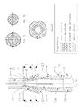
- FIG. 1 is a side profile exterior view of an exemplary variable volume induction nozzle in accordance with the preferred embodiment of the present invention
- FIG. 2 is a longitudinal cross-section view of the exemplary variable volume induction nozzle of FIG. 1 , taken along line A-A, showing the impinger pod in the fully open position;
- FIG. 3 is a longitudinal cross-section view of the exemplary variable volume induction nozzle of FIG. 1 , taken along line A-A, showing the impinger pod in an intermediate position;
- FIG. 4 is a longitudinal cross-section view of the exemplary variable volume induction nozzle of FIG. 1 , taken along line A-A, showing the impinger pod in the fully closed position;
- FIG. 5A is the longitudinal cross-section view of FIG. 2 , corresponding to the fully open pod position, with cross-hatching designating four airflow regions;
- FIG. 5B is an axial cross-section view of the exemplary nozzle, taken along line B-B in FIG. 5A , with cross-hatching designating two airflow regions;
- FIG. 5C is an axial cross-section view of the exemplary nozzle, taken along line C-C in FIG. 5A , with cross-hatching designating two airflow regions;
- FIG. 5D is an axial cross-section view of the exemplary nozzle, taken along line D-D in FIG. 5A , with cross-hatching designating two airflow regions;
- FIG. 6A is the longitudinal cross-section view of FIG. 3 , corresponding to the intermediate pod position, with cross-hatching designating four airflow regions;
- FIG. 6B is an axial cross-section view of the exemplary nozzle, taken along line B-B in FIG. 6A , with cross-hatching designating two airflow regions;
- FIG. 6C is an axial cross-section view of the exemplary nozzle, taken along line C-C in FIG. 6A , with cross-hatching designating two airflow regions;
- FIG. 6D is an axial cross-section view of the exemplary nozzle, taken along line D-D in FIG. 6A , with cross-hatching designating two airflow regions;
- FIG. 7A is the longitudinal cross-section view of FIG. 4 , corresponding to the fully closed pod position, with cross-hatching designating four airflow regions;
- FIG. 7B is an axial cross-section view of the exemplary nozzle, taken along line B-B in FIG. 7A , with cross-hatching designating two airflow regions;
- FIG. 7C is an axial cross-section view of the exemplary nozzle, taken along line C-C in FIG. 7A , with cross-hatching designating two airflow regions;
- FIG. 7D is an axial cross-section view of the exemplary nozzle, taken along line D-D in FIG. 7A , with cross-hatching designating two airflow regions;
- FIG. 8 is a schematic diagram depicting an exemplary control system for the preferred embodiment of the present invention.
- the preferred embodiment of the present invention comprises a variable volume induction nozzle, which is vertically connected to the primary exhaust gas outlet 1 of a variable speed fan by way of a flange at the nozzle exhaust inlet 2 .
- the nozzle wall comprises a tubular lower section 3 and a tapered frusto-conical upper section 4 .
- the nozzle further comprises a frusto-conical windband 5 , which is attached to the upper section 4 of the nozzle wall by multiple mounting brackets 6 .
- FIGS. 2-4 depict cross-section views of the variable volume induction nozzle.
- FIG. 2 depicts the nozzle in the fully open position, corresponding to a condition of maximum primary exhaust flow, with the fan operating at maximum speed.
- FIG. 4 depicts the nozzle in the fully closed position, corresponding to a condition of minimum primary effluent flow, with the fan operating at minimum speed.
- FIG. 3 depicts the nozzle in an intermediate position, with the fan operating between minimum and maximum speed.
- the fan outlet 1 defines an annular exhaust gas passageway 19 surrounding the fan motor housing 7 .
- the annular fan outlet exhaust gas passageway 19 fluidly communicates through the nozzle inlet 2 with a uniform annular lower effluent passage 20 in the nozzle's lower section 3 .
- This lower effluent passage 20 is defined by an axially-disposed tubular pod lower section 14 .
- a conically tapered pod upper section 16 the taper of which matches that of the upper section 4 of the nozzle wall—defines a converging annular upper effluent passage 23 .
- the rounded pod tip 22 is aligned with the nozzle's exhaust discharge outlet 28 , such that the exhaust flow from the annular upper effluent passage 23 converges linearly at a first exhaust convergence point 21 , downstream of the windband inlet opening 24 , thereby inducing a laminar annular inflow of ambient air through the windband inlet opening 24 .
- the pod tip 22 projects through the nozzle's exhaust gas discharge outlet 28 and extends to a location below the windband outlet opening 25 .
- the motion of the impinger pod between the open position and the closed position is controlled by a linear actuator 10 acting through an actuator screw 12 on a screw travel nut 13 connected to the pod's upper section 16 .
- the pod's tubular lower section 14 moves up and down, in response to the linear actuator 10 , along a conforming tubular guide sleeve 9 , with its travel alignment controlled by a guide key 18 within a conjugate guide track 17 .
- a velocity sensor-processor 27 is located, which takes periodic measurements of the discharge velocity of the exhaust gas, compares it with a velocity set point, and signals the linear actuator 10 to either lower the impinger pod to a more open position, if the measured discharge velocity is above the set point, or raise the pod to a more closed position, if the measured discharge velocity is below the set point.
- the converging annular upper effluent passage 23 generates a uniform accelerated primary airflow region 47 , which maximizes the induced airflow 48 through the windband inlet opening 24 and generates a combined laminar discharge airflow 49 through the windband outlet opening 25 .
- FIG. 8 depicts exemplary control system for the variable volume induction nozzle 45 and associated fan assembly.
- the flow rate of the primary exhaust has 30 is monitored 31 , along with the static pressure 32 of the exhaust gas upstream of the fan 44 .
- a master controller (CPU) 42 activates a bypass air actuator 36 to control the opening and closing of a bypass air damper 35 , so that a greater volume of bypass air 37 is introduced when the primary exhaust flow rate 31 and/or static pressure 32 drop below designated design values.
- the primary exhaust gas 30 augmented as needed by the bypass air 37 , enters the fan plenum 43 through the fan's isolation damper 33 , controlled by a spring-return actuator 34 . From the fan 44 , the augmented exhaust gas 30 37 flows through the nozzle 45 , where its flow rate is accelerated to a degree determined by the position of the impinger pod, as controlled by the linear actuator 10 .
- the CPU 42 monitors flow velocity and/or velocity pressure 38 near the nozzle outlet 25 and uses such data to adjust fan speed through a variable frequency drive 39 (connected to an electric power source 40 ), as well as pod position through the linear actuator 10 , to achieve a required plume rise based on a design discharge velocity 46 .
- the CPU 42 calculates the design discharge velocity 46 using the Briggs Equation and the prevailing cross-wind velocity, as measured by an anemometer 41 at the building roofline.
Landscapes
- Engineering & Computer Science (AREA)
- Mechanical Engineering (AREA)
- General Engineering & Computer Science (AREA)
- Physics & Mathematics (AREA)
- Fluid Mechanics (AREA)
- Jet Pumps And Other Pumps (AREA)
- Ventilation (AREA)
Abstract
Description
h se =h s +h r −h d
Where:
h r=3.0d e(V e /U H)
-
- de is the effective (hydraulic) diameter (ft) at the terminal discharge point of the system computed from: de=(4Ae/π)^(½), where Ae is the cross-sectional area of the discharge opening
- Ve is the equipment exit velocity (ft/min) at cross wind velocity
- UH is the cross wind velocity (ft/min) at the building roofline
This adaptation of the Briggs Equation is a function of dynamic variables. Equipment performance data must be acquired using dynamic testing parameters. Specifically, the equipment exit velocity, Ve, must be measured with the specified design cross wind, UH, applied to the system. Moreover, it is a necessary condition that the effective diameter, de, be determined for the location where the equipment exit velocity, Ve, was measured. It is recommended that this location be final discharge point (i.e. terminal location) of the exhaust system to the atmosphere. For this form of the Briggs equation for plume rise to be applicable, the discharge velocity profile at the system discharge must be characterized as uniform. A uniform velocity profile is defined as having minimal velocity gradients in the transverse plane of system discharge.
hr=min{βhx, βhf}
h x=[(3F m x)/(βj 2 U H 2)]^(⅓)
h f={0.9[F m(U H /U*)]^(½)}/(U Hβj)
-
- H is the building height above ground level (ft)
- U* is the friction velocity (ft)
- z0 is the surface roughness length (ft) which can be obtained from the Atmospheric Boundary Layer Parameters Table in
Chapter 45 of the ASHRAE 2011 HVAC Design Handbook.
The possibility of stack wake downwash, hd, is an essential component to evaluate when computing the effective stack height of an exhaust system. Stack wake downwash occurs where low velocity exhaust streams are pulled downward by negative pressures immediately downstream of the exhaust system discharge. The amount of stack wake downwash in (ft) can be obtained from hd=de[3.0−β(V e /U H)]
BHP2=[(RPM2/RPM1)3]BHP1
-
- BHP is the brake horsepower consumption of the system
- RPM is the speed of the fan
-
Subscripts
Claims (15)
Priority Applications (1)
| Application Number | Priority Date | Filing Date | Title |
|---|---|---|---|
| US14/209,154 US10036403B2 (en) | 2013-03-20 | 2014-03-13 | Variable volume induction nozzle |
Applications Claiming Priority (2)
| Application Number | Priority Date | Filing Date | Title |
|---|---|---|---|
| US201361803520P | 2013-03-20 | 2013-03-20 | |
| US14/209,154 US10036403B2 (en) | 2013-03-20 | 2014-03-13 | Variable volume induction nozzle |
Publications (2)
| Publication Number | Publication Date |
|---|---|
| US20140286767A1 US20140286767A1 (en) | 2014-09-25 |
| US10036403B2 true US10036403B2 (en) | 2018-07-31 |
Family
ID=51569262
Family Applications (1)
| Application Number | Title | Priority Date | Filing Date |
|---|---|---|---|
| US14/209,154 Active 2037-06-01 US10036403B2 (en) | 2013-03-20 | 2014-03-13 | Variable volume induction nozzle |
Country Status (1)
| Country | Link |
|---|---|
| US (1) | US10036403B2 (en) |
Families Citing this family (3)
| Publication number | Priority date | Publication date | Assignee | Title |
|---|---|---|---|---|
| US7682231B2 (en) * | 2004-01-20 | 2010-03-23 | Greenheck Fan Corporation | Exhaust fan assembly |
| CN108252250B (en) * | 2016-12-28 | 2021-08-27 | 南京德朔实业有限公司 | Hair drier and air speed adjusting device thereof |
| US11320159B2 (en) * | 2018-09-19 | 2022-05-03 | Air Distribution Technologies Ip, Llc | Nozzle assembly for exhaust fan unit of HVAC system |
Citations (27)
| Publication number | Priority date | Publication date | Assignee | Title |
|---|---|---|---|---|
| US2188564A (en) * | 1939-02-08 | 1940-01-30 | Floyd F Schultz | Draft regulator for chimneys |
| US2483922A (en) * | 1946-09-05 | 1949-10-04 | John H Messer | Chimney draft control |
| US2626557A (en) * | 1950-08-28 | 1953-01-27 | Hersch Sam | Ventilator |
| US3010692A (en) * | 1959-11-20 | 1961-11-28 | Robertson Co H H | Expansible conical plug valve |
| US3525474A (en) * | 1968-12-09 | 1970-08-25 | Us Air Force | Jet pump or thrust augmentor |
| US3528614A (en) * | 1967-05-13 | 1970-09-15 | Ltg Lufttechnische Gmbh | Fluid admixing apparatus |
| US3719032A (en) * | 1971-10-26 | 1973-03-06 | G Cash | Induction condenser |
| US4344370A (en) * | 1980-07-24 | 1982-08-17 | Industrial Air, Inc. | Apparatus for discharging exhaust gas at high velocity |
| US4422524A (en) * | 1982-03-22 | 1983-12-27 | Lockheed Corporation | Variable shape, fluid flow nozzle for sound suppression |
| US4806076A (en) * | 1988-02-22 | 1989-02-21 | Strobic Air Corporation | Radial upblast exhaust fan apparatus |
| US5439349A (en) * | 1994-11-15 | 1995-08-08 | Kupferberg; Minel | Exhaust fan apparatus |
| US5938527A (en) * | 1996-11-20 | 1999-08-17 | Mitsubishi Denki Kabushiki Kaisha | Air ventilation or air supply system |
| US6112850A (en) * | 1999-09-07 | 2000-09-05 | Met Pro Corporation | Acoustic silencer nozzle |
| US6431974B1 (en) * | 2000-03-29 | 2002-08-13 | Met Pro Corporation | Acoustic wind band |
| US6509081B1 (en) * | 2000-09-28 | 2003-01-21 | The Boeing Company | No-septum acoustic sandwich panel, and apparatus and method for suppressing noise in a nozzle |
| US6676503B2 (en) * | 2001-12-13 | 2004-01-13 | Plasticair Inc. | Exhaust gas nozzle for fan |
| US6890252B2 (en) | 2000-05-01 | 2005-05-10 | Mingsheng Liu | Fume hood exhaust stack system |
| US20050170767A1 (en) * | 2004-01-20 | 2005-08-04 | Greenheck Fan Corporation | Exhaust fan assembly |
| US20060179815A1 (en) * | 2003-09-08 | 2006-08-17 | Means James L | Passive exhaust suppressor and method |
| US7241214B2 (en) * | 2004-01-26 | 2007-07-10 | Plasticair, Inc. | Upblast fan nozzle with wind deflecting panels |
| US20070298700A1 (en) * | 2006-06-21 | 2007-12-27 | Dipti Datta | Exhaust gas stack |
| US7547249B2 (en) * | 2004-07-15 | 2009-06-16 | Greenheck Fan Corporation | Exhaust fan assembly having H-out nozzle |
| WO2009091477A1 (en) | 2008-01-18 | 2009-07-23 | Mpc Inc. | Control system for exhaust gas fan system |
| US20120322358A1 (en) | 2011-06-14 | 2012-12-20 | Wendorski Ronald L | Variable-volume exhaust system |
| US8974272B2 (en) * | 2011-05-20 | 2015-03-10 | Dyna-Tech Sales Corporation | Aspirating induction nozzle |
| US9233386B2 (en) * | 2012-02-01 | 2016-01-12 | Dyna-Tech Sales Corporation | Apparatus and method for preventing crosswind interference in induction nozzles |
| US9371836B2 (en) * | 2012-10-25 | 2016-06-21 | Dyna-Tech Sales Corporation | Mixed flow fan assembly |
-
2014
- 2014-03-13 US US14/209,154 patent/US10036403B2/en active Active
Patent Citations (28)
| Publication number | Priority date | Publication date | Assignee | Title |
|---|---|---|---|---|
| US2188564A (en) * | 1939-02-08 | 1940-01-30 | Floyd F Schultz | Draft regulator for chimneys |
| US2483922A (en) * | 1946-09-05 | 1949-10-04 | John H Messer | Chimney draft control |
| US2626557A (en) * | 1950-08-28 | 1953-01-27 | Hersch Sam | Ventilator |
| US3010692A (en) * | 1959-11-20 | 1961-11-28 | Robertson Co H H | Expansible conical plug valve |
| US3528614A (en) * | 1967-05-13 | 1970-09-15 | Ltg Lufttechnische Gmbh | Fluid admixing apparatus |
| US3525474A (en) * | 1968-12-09 | 1970-08-25 | Us Air Force | Jet pump or thrust augmentor |
| US3719032A (en) * | 1971-10-26 | 1973-03-06 | G Cash | Induction condenser |
| US4344370A (en) * | 1980-07-24 | 1982-08-17 | Industrial Air, Inc. | Apparatus for discharging exhaust gas at high velocity |
| US4422524A (en) * | 1982-03-22 | 1983-12-27 | Lockheed Corporation | Variable shape, fluid flow nozzle for sound suppression |
| US4806076A (en) * | 1988-02-22 | 1989-02-21 | Strobic Air Corporation | Radial upblast exhaust fan apparatus |
| US5439349A (en) * | 1994-11-15 | 1995-08-08 | Kupferberg; Minel | Exhaust fan apparatus |
| US5938527A (en) * | 1996-11-20 | 1999-08-17 | Mitsubishi Denki Kabushiki Kaisha | Air ventilation or air supply system |
| US6112850A (en) * | 1999-09-07 | 2000-09-05 | Met Pro Corporation | Acoustic silencer nozzle |
| US6431974B1 (en) * | 2000-03-29 | 2002-08-13 | Met Pro Corporation | Acoustic wind band |
| US6890252B2 (en) | 2000-05-01 | 2005-05-10 | Mingsheng Liu | Fume hood exhaust stack system |
| US6509081B1 (en) * | 2000-09-28 | 2003-01-21 | The Boeing Company | No-septum acoustic sandwich panel, and apparatus and method for suppressing noise in a nozzle |
| US6676503B2 (en) * | 2001-12-13 | 2004-01-13 | Plasticair Inc. | Exhaust gas nozzle for fan |
| US20060179815A1 (en) * | 2003-09-08 | 2006-08-17 | Means James L | Passive exhaust suppressor and method |
| US20050170767A1 (en) * | 2004-01-20 | 2005-08-04 | Greenheck Fan Corporation | Exhaust fan assembly |
| US7241214B2 (en) * | 2004-01-26 | 2007-07-10 | Plasticair, Inc. | Upblast fan nozzle with wind deflecting panels |
| US7547249B2 (en) * | 2004-07-15 | 2009-06-16 | Greenheck Fan Corporation | Exhaust fan assembly having H-out nozzle |
| US20070298700A1 (en) * | 2006-06-21 | 2007-12-27 | Dipti Datta | Exhaust gas stack |
| WO2009091477A1 (en) | 2008-01-18 | 2009-07-23 | Mpc Inc. | Control system for exhaust gas fan system |
| US20110053488A1 (en) * | 2008-01-18 | 2011-03-03 | Mpc Inc. | Control system for exhaust gas fan system |
| US8974272B2 (en) * | 2011-05-20 | 2015-03-10 | Dyna-Tech Sales Corporation | Aspirating induction nozzle |
| US20120322358A1 (en) | 2011-06-14 | 2012-12-20 | Wendorski Ronald L | Variable-volume exhaust system |
| US9233386B2 (en) * | 2012-02-01 | 2016-01-12 | Dyna-Tech Sales Corporation | Apparatus and method for preventing crosswind interference in induction nozzles |
| US9371836B2 (en) * | 2012-10-25 | 2016-06-21 | Dyna-Tech Sales Corporation | Mixed flow fan assembly |
Also Published As
| Publication number | Publication date |
|---|---|
| US20140286767A1 (en) | 2014-09-25 |
Similar Documents
| Publication | Publication Date | Title |
|---|---|---|
| US9897111B2 (en) | Aspirating induction nozzle with flow transition | |
| Cao et al. | Performance evaluation of different air distribution systems for removal of concentrated emission contaminants by using vortex flow ventilation system | |
| Cao et al. | Study of the vortex principle for improving the efficiency of an exhaust ventilation system | |
| US9423128B2 (en) | Control system for exhaust gas fan system | |
| CN111706951B (en) | A Thermal Comfort Ventilation and Pollutant Control Method for Air Stability in Limited Space | |
| US10036403B2 (en) | Variable volume induction nozzle | |
| CN206810835U (en) | Air-valve control device, control system and vent cabinet | |
| Liu et al. | Study on pressure control and energy saving of cleanroom in purification air conditioning system | |
| Wang et al. | Numerical study on pollutant removal performance of vortex ventilation with different pollution source locations | |
| Liang et al. | Constant static pressure strategy for residential kitchen exhaust system: Deducing control parameters from required exhaust rate and non-distributed data transmission | |
| Cao et al. | Performance of novel overhead crane fume-collecting hood for pollutant removal | |
| CN202403365U (en) | Large welding workshop ventilation and air-conditioning system | |
| Zhou et al. | Performance evaluation of a novel relay parallel push-pull ventilation system for long-distance pollution control | |
| CN110542189B (en) | Laboratory ventilation system and method thereof | |
| CN205690607U (en) | A kind of application paint spray booth blast regulation system | |
| Saathoff et al. | Contamination of fresh air intakes due to downwash from a rooftop structure | |
| US7077739B2 (en) | High velocity and high dilution exhaust system | |
| KR100585238B1 (en) | IAW control system through active response ventilation | |
| Li et al. | Industrial ventilation design method | |
| Vincent et al. | CFD Analysis of Wind-Driven Natural Ventilation in Building Models | |
| CN105525683B (en) | A kind of separate type steelframe glass architecture | |
| Woods et al. | Evaluation of capture efficiencies of large push-pull ventilation systems with both visual and tracer techniques | |
| Popov et al. | Impact of the method of air suction on the energy efficiency of fan systems | |
| Sakakibara et al. | The Evaluation of Air Blowing Method of Variable-Air-Conditioning-System using Coanda Effect by Computational Fluid Dynamics | |
| CN205659970U (en) | Environmental protection exhaust regulation and controlling system |
Legal Events
| Date | Code | Title | Description |
|---|---|---|---|
| AS | Assignment |
Owner name: DYNA-TECH SALES CORPORATION, NEW JERSEY Free format text: ASSIGNMENT OF ASSIGNORS INTEREST;ASSIGNORS:MORNAN, BRIAN J;BEITZ, FRANK J;ALMERINI, NICHOLAS J;REEL/FRAME:032432/0017 Effective date: 20140313 |
|
| STCF | Information on status: patent grant |
Free format text: PATENTED CASE |
|
| MAFP | Maintenance fee payment |
Free format text: PAYMENT OF MAINTENANCE FEE, 4TH YR, SMALL ENTITY (ORIGINAL EVENT CODE: M2551); ENTITY STATUS OF PATENT OWNER: SMALL ENTITY Year of fee payment: 4 |
|
| FEPP | Fee payment procedure |
Free format text: 7.5 YR SURCHARGE - LATE PMT W/IN 6 MO, SMALL ENTITY (ORIGINAL EVENT CODE: M2555); ENTITY STATUS OF PATENT OWNER: SMALL ENTITY |
|
| MAFP | Maintenance fee payment |
Free format text: PAYMENT OF MAINTENANCE FEE, 8TH YR, SMALL ENTITY (ORIGINAL EVENT CODE: M2552); ENTITY STATUS OF PATENT OWNER: SMALL ENTITY Year of fee payment: 8 |