US10045936B2 - Method for manufacturing transdermal-absorption sheet - Google Patents
Method for manufacturing transdermal-absorption sheet Download PDFInfo
- Publication number
- US10045936B2 US10045936B2 US14/709,644 US201514709644A US10045936B2 US 10045936 B2 US10045936 B2 US 10045936B2 US 201514709644 A US201514709644 A US 201514709644A US 10045936 B2 US10045936 B2 US 10045936B2
- Authority
- US
- United States
- Prior art keywords
- drug
- mold
- needle
- containing solution
- nozzle
- Prior art date
- Legal status (The legal status is an assumption and is not a legal conclusion. Google has not performed a legal analysis and makes no representation as to the accuracy of the status listed.)
- Expired - Fee Related, expires
Links
Images


Classifications
-
- A—HUMAN NECESSITIES
- A61—MEDICAL OR VETERINARY SCIENCE; HYGIENE
- A61K—PREPARATIONS FOR MEDICAL, DENTAL OR TOILETRY PURPOSES
- A61K9/00—Medicinal preparations characterised by special physical form
- A61K9/0012—Galenical forms characterised by the site of application
- A61K9/0019—Injectable compositions; Intramuscular, intravenous, arterial, subcutaneous administration; Compositions to be administered through the skin in an invasive manner
- A61K9/0021—Intradermal administration, e.g. through microneedle arrays or needleless injectors
-
- A—HUMAN NECESSITIES
- A61—MEDICAL OR VETERINARY SCIENCE; HYGIENE
- A61M—DEVICES FOR INTRODUCING MEDIA INTO, OR ONTO, THE BODY; DEVICES FOR TRANSDUCING BODY MEDIA OR FOR TAKING MEDIA FROM THE BODY; DEVICES FOR PRODUCING OR ENDING SLEEP OR STUPOR
- A61M37/00—Other apparatus for introducing media into the body; Percutany, i.e. introducing medicines into the body by diffusion through the skin
- A61M37/0015—Other apparatus for introducing media into the body; Percutany, i.e. introducing medicines into the body by diffusion through the skin by using microneedles
-
- B—PERFORMING OPERATIONS; TRANSPORTING
- B29—WORKING OF PLASTICS; WORKING OF SUBSTANCES IN A PLASTIC STATE IN GENERAL
- B29C—SHAPING OR JOINING OF PLASTICS; SHAPING OF MATERIAL IN A PLASTIC STATE, NOT OTHERWISE PROVIDED FOR; AFTER-TREATMENT OF THE SHAPED PRODUCTS, e.g. REPAIRING
- B29C39/00—Shaping by casting, i.e. introducing the moulding material into a mould or between confining surfaces without significant moulding pressure; Apparatus therefor
- B29C39/22—Component parts, details or accessories; Auxiliary operations
- B29C39/24—Feeding the material into the mould
-
- A—HUMAN NECESSITIES
- A61—MEDICAL OR VETERINARY SCIENCE; HYGIENE
- A61M—DEVICES FOR INTRODUCING MEDIA INTO, OR ONTO, THE BODY; DEVICES FOR TRANSDUCING BODY MEDIA OR FOR TAKING MEDIA FROM THE BODY; DEVICES FOR PRODUCING OR ENDING SLEEP OR STUPOR
- A61M37/00—Other apparatus for introducing media into the body; Percutany, i.e. introducing medicines into the body by diffusion through the skin
- A61M37/0015—Other apparatus for introducing media into the body; Percutany, i.e. introducing medicines into the body by diffusion through the skin by using microneedles
- A61M2037/0046—Solid microneedles
-
- A—HUMAN NECESSITIES
- A61—MEDICAL OR VETERINARY SCIENCE; HYGIENE
- A61M—DEVICES FOR INTRODUCING MEDIA INTO, OR ONTO, THE BODY; DEVICES FOR TRANSDUCING BODY MEDIA OR FOR TAKING MEDIA FROM THE BODY; DEVICES FOR PRODUCING OR ENDING SLEEP OR STUPOR
- A61M37/00—Other apparatus for introducing media into the body; Percutany, i.e. introducing medicines into the body by diffusion through the skin
- A61M37/0015—Other apparatus for introducing media into the body; Percutany, i.e. introducing medicines into the body by diffusion through the skin by using microneedles
- A61M2037/0053—Methods for producing microneedles
-
- B—PERFORMING OPERATIONS; TRANSPORTING
- B29—WORKING OF PLASTICS; WORKING OF SUBSTANCES IN A PLASTIC STATE IN GENERAL
- B29L—INDEXING SCHEME ASSOCIATED WITH SUBCLASS B29C, RELATING TO PARTICULAR ARTICLES
- B29L2031/00—Other particular articles
- B29L2031/753—Medical equipment; Accessories therefor
- B29L2031/7544—Injection needles, syringes
-
- B—PERFORMING OPERATIONS; TRANSPORTING
- B29—WORKING OF PLASTICS; WORKING OF SUBSTANCES IN A PLASTIC STATE IN GENERAL
- B29L—INDEXING SCHEME ASSOCIATED WITH SUBCLASS B29C, RELATING TO PARTICULAR ARTICLES
- B29L2031/00—Other particular articles
- B29L2031/756—Microarticles, nanoarticles
-
- F—MECHANICAL ENGINEERING; LIGHTING; HEATING; WEAPONS; BLASTING
- F04—POSITIVE - DISPLACEMENT MACHINES FOR LIQUIDS; PUMPS FOR LIQUIDS OR ELASTIC FLUIDS
- F04C—ROTARY-PISTON, OR OSCILLATING-PISTON, POSITIVE-DISPLACEMENT MACHINES FOR LIQUIDS; ROTARY-PISTON, OR OSCILLATING-PISTON, POSITIVE-DISPLACEMENT PUMPS
- F04C2270/00—Control; Monitoring or safety arrangements
- F04C2270/04—Force
- F04C2270/042—Force radial
- F04C2270/0421—Controlled or regulated
Definitions
- the present invention relates to a method for manufacturing a transdermal-absorption sheet, and in particular, to a technique for concentrating a drug at needle-like protruding portions.
- a method has been carried out in which a chemical is injected by using a transdermal-absorption sheet provided with needle-like protruding portions having a high aspect ratio and containing a drug to insert the needle-like protruding portions into the skin.
- the drug needs to be mixed into the sheet.
- Many drugs are expensive, and thus, the drug needs to be contained in the sheet so as to concentrate at the needle-like protruding portions.
- a method for manufacturing a transdermal-absorption sheet a method is known in which a polymer solution or the like is poured into a mold on which needle-like recessed portions that are inverted shapes of needle-like protruding portions are formed, to transfer the shapes.
- a polymer solution or the like is poured into a mold on which needle-like recessed portions that are inverted shapes of needle-like protruding portions are formed, to transfer the shapes.
- Japanese Patent Application Laid-Open No. 2011-078617 discloses use of a stamper for microneedle sheets in which through-holes penetrating a parent material are made at the bottoms of the recessed portions.
- PTL 1 discloses a method of first coating a surface of the stamper with a solution of a diluted drug, subsequently scraping off extra solution using a squeegee or the like, drying the drug solution, and then coating the dried drug solution with a needle raw material.
- Japanese Patent Application Laid-Open No. 2009-195583 discloses a method for manufacturing a sheet in which microneedle-like protrusions are accumulated.
- the sheet can be accurately manufactured in one step by filling a flexible substrate with a thick liquid consisting of a mixture of a target substance and a base utilizing a centrifugal force, while drying and hardening the liquid.
- the drug solution is applied to the stamper, and the extra solution is scraped off using the squeegee or the like.
- the drug solution which is applied to the areas other than the recessed portions is not used to fill the recessed portions, leading to a loss in drug solution.
- the method in PTL 2 utilizes the centrifugal force and is thus not a continuous process but is a batch process. Consequently, the method in PTL 2 does not achieve high production efficiency.
- the present invention aims to provide a method which enables a drug to be concentrated at needle-like protruding portions and which further allows transdermal-absorption sheets to be manufactured at high production efficiency.
- a method for manufacturing a transdermal-absorption sheet according to an aspect of the present invention is for manufacturing a transdermal-absorption sheet with needle-like protruding portions each including a drug-containing layer and a non-drug-containing layer, the method including: a step of preparing a mold with two-dimensionally arranged needle-like recessed portions and a liquid feeding apparatus comprising a nozzle with an opening; a step of filling the two-dimensionally arranged needle-like recessed portions with a drug-containing solution by repeating a filling step of feeding the drug-containing solution from the liquid feeding apparatus to the mold and filling one or more of the needle-like recessed portions with the drug-containing solution through the nozzle aligned over the needle-like recessed portions in a state where the nozzle and a front surface of the mold are brought in contact with each other, and a moving step of moving the liquid feeding apparatus relative to the mold in a state where the nozzle and the front surface of the mold are brought in contact with each other; a step
- the two-dimensionally arranged needle-like recessed portions are filled with the drug-containing solution so that filling is performed on one line or a plurality of lines at a time.
- the filling step includes pressurizing an inside of the nozzle.
- a pressing force with which the nozzle and the mold are brought into contact with each other is equal to or stronger than a pressurizing force inside the nozzle.
- the filling step includes sucking a back surface of the mold with a reduced pressure.
- the pressing force with which the nozzle and the mold are brought into contact with each other in the filling step is stronger than a pressing force with which the nozzle and the mold are brought into contact with each other in the moving step.
- feeding of the drug-containing solution from the liquid feeding apparatus to the mold is stopped while the nozzle is positioned over an area other than the needle-like recessed portions in the mold.
- feeding of the drug-containing solution from the liquid feeding apparatus to the mold is started before the nozzle is positioned over the needle-like recessed portions, and the feeding of the drug-containing solution to the mold is stopped before the nozzle is positioned over the area other than the needle-like recessed portions in the mold.
- At least one of the nozzle and the front surface of the mold is made of an elastically deformable raw material.
- the mold comprises an air vent hole at a tip of each of the needle-like recessed portions.
- the step of forming the polymer sheet comprises a step of feeding the non-drug-containing solution to the mold with the needle-like recessed portions filled with the drug-containing solution, and then drying and solidifying the drug-containing solution and the non-drug-containing solution to form the drug-containing layer and the non-drug-containing layer.
- the step of forming the polymer sheet comprises a step of drying and solidifying the drug-containing solution filled in the needle-like recessed portions in the mold to form the drug-containing layer, feeding the non-drug-containing solution to the mold in which the drug-containing layer is formed in the needle-like recessed portions, and then drying and solidifying the non-drug-containing solution to form the non-drug containing layer.
- the step of forming the polymer sheet comprises a step of applying the non-drug-containing solution onto a surface of another support, attaching the another support onto which the non-drug-containing solution is applied to the mold with the needle-like recessed portions filled with the drug-containing solution, and drying and solidifying the drug-containing solution and the non-drug-containing solution to form the drug-containing layer and the non-drug-containing layer.
- the step of forming the polymer sheet comprises performing at least one of pressurization from the front surface of the mold and reduced pressure suction from the back surface of the mold, when drying and solidifying the drug-containing solution contained in the needle-like recessed portions in the mold.
- the step of forming the polymer sheet comprises performing at least one of pressurization of the non-drug-containing solution from a front surface of the mold and reduced pressure suction of the non-drug-containing solution from a back surface of the mold.
- the drug is peptide, protein, nucleic acid, polysaccharide, a vaccine, a medical compound belonging to a water-soluble low-molecular-weight compound, or a cosmetic component.
- the needle-like protruding portion contains the drug and hydroxyethyl starch in a tip thereof, and contains hydroxyethyl starch and hyaluronic acid in a base thereof.
- the needle-like protruding portion contains the drug and chondroitin sulfate in the tip thereof, and contains hydroxyethyl starch in the base thereof.
- the needle-like protruding portions comprise the drug-containing layer and the non-drug-containing layer, the drug-containing layer further contains hydroxyethyl starch, and the non-drug-containing layer contains hydroxyethyl starch and hyaluronic acid.
- the needle-like protruding portions comprise the drug-containing layer and the non-drug-containing layer, the drug-containing layer further contains chondroitin sulfate, and the non-drug-containing layer contains hydroxyethyl starch.
- a transdermal-absorption sheet can be efficiently manufactured which allows a drug to be eccentrically located in needle-like protruding portions.
- FIG. 1A is a perspective view of a pyramidal microneedle (needle-like protruding portion) on a transdermal-absorption sheet.
- FIG. 1B is a cross-sectional view of the pyramidal microneedle (needle-like protruding portion) on the transdermal-absorption sheet.
- FIG. 2A is a perspective view of a conical microneedle (needle-like protruding portion) on the transdermal-absorption sheet.
- FIG. 2B is a cross-sectional view of the conical microneedle (needle-like protruding portion) on the transdermal-absorption sheet.
- FIG. 3A is a process diagram of a method for manufacturing a mold.
- FIG. 3B is a process diagram of the method for manufacturing the mold.
- FIG. 3C is a process diagram of the method for manufacturing the mold.
- FIG. 4A is a front view of a mold provided with a frame.
- FIG. 4B is a perspective view of the mold provided with the frame.
- FIG. 4C is a front view of the mold provided with the frame.
- FIG. 4D is a perspective view of the mold provided with the frame.
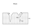
- FIG. 5 is a cross-sectional view depicting a mold in another embodiment.
- FIG. 6 is a cross-sectional view depicting a mold complex.
- FIG. 7A is a schematic diagram depicting a step of filling the mold with a drug-containing solution.
- FIG. 7B is a schematic diagram depicting the step of filling the mold with the drug-containing solution.
- FIG. 7C is a schematic diagram depicting the step of filling the mold with the drug-containing solution.
- FIG. 8 is a perspective view depicting a tip of a nozzle.
- FIG. 9 is a perspective view depicting a tip of another nozzle.
- FIG. 10 is a partially enlarged view of the mold and the tip of the nozzle while filling.
- FIG. 11 is a partially enlarged view of the mold and the tip of the nozzle while moving.
- FIG. 12 is a diagram illustrating the relation between the liquid pressure in the nozzle and feeding of the drug-containing solution.
- FIG. 13A is a diagram illustrating a process of forming a polymer sheet.
- FIG. 13B is a diagram illustrating the process of forming the polymer sheet.
- FIG. 13C is a diagram illustrating the process of forming the polymer sheet.
- FIG. 14A is a diagram illustrating another process of forming the polymer sheet.
- FIG. 14B is a diagram illustrating the another process of forming the polymer sheet.
- FIG. 14C is a diagram illustrating the another process of forming the polymer sheet.
- FIG. 14D is a diagram illustrating the another process of forming the polymer sheet.
- FIG. 15A is a diagram illustrating yet another process of forming the polymer sheet.
- FIG. 15B is a diagram illustrating the yet another process of forming the polymer sheet.
- FIG. 15C is a diagram illustrating the yet another process of forming the polymer sheet.
- FIG. 15D is a diagram illustrating the yet another process of forming the polymer sheet.
- FIG. 16 is a diagram illustrating a peeling-off step.
- FIG. 17 is a diagram illustrating another peeling-off step.
- FIG. 18 is a diagram illustrating still yet another process of forming the polymer sheet.
- FIG. 19 is a plan view and a side view of an original plate.
- transdermal-absorption sheet with needle-like protruding portions arranged in an array
- a method for manufacturing the transdermal-absorption sheet is described.
- the transdermal-absorption sheet is described, but the present invention may be applied to a functional film other than the transdermal-absorption sheet which has a needle-like protruding portions arranged in an array.
- needle-like protruding portions (also referred to as microneedles) on a transdermal-absorption sheet are described which sheet is manufactured by a method for manufacturing a transdermal-absorption sheet according to the embodiment of the present invention.
- an example of quadrangular pyramidal needle-like protruding portions is described, however, the present invention is not limited to this shape.
- the microneedle (needle-like protruding portion) 10 formed on the transdermal-absorption sheet needs to be shaped as follows so as to be stuck several hundred ⁇ m deep into the surface of the skin: (1) The tip is sufficiently pointed, and the diameter of the needle penetrating the skin is sufficiently small (the aspect ratio of length/diameter is high), and (2) the microneedle has a sufficient strength (the needle does not bend).
- a ridge line 10 A of the microneedle 10 is preferably shaped to be curved toward the inside of the microneedle.
- the microneedle with such a shape can be made difficult to bend by sufficiently sharpening the tip, while widening the root.
- the ridge lines 10 A, 10 A of a quadrangular pyramidal microneedle preferably extend from a quadrangular pyramidal surface 10 C between the ridge lines.
- the shape of the microneedle 10 is preferably such that a bottom surface is within the range of 0.1 ⁇ m or more and 1,000 ⁇ m or less on a side X, and 0.3 ⁇ m or more and 3,000 ⁇ m or less in height. More preferably, the bottom surface is within the range of 10 ⁇ m or more and 400 ⁇ m or less on a side X, and 30 ⁇ m or more and 1,200 ⁇ m or less in height.
- the maximum depth Z of curve of the ridge line 10 A is preferably 0.04 ⁇ L or more and 0.2 ⁇ L or less.
- the radius of curvature R of a tip 10 B of the microneedle is preferably 20 ⁇ m or less, and more preferably 15 ⁇ m or less.
- FIGS. 1A and 1B depict the quadrangular pyramidal microneedle 10 .
- a conical microneedle depicted in FIGS. 2A and 2B and microneedles having other pyramids such as a triangular pyramid preferably have similar sizes.
- the diameter X of the bottom surface is preferably within the range of 0.1 ⁇ m or more and 1,000 ⁇ m or less, and more preferably within the range of 50 ⁇ m or more and 500 ⁇ m or less.
- the maximum depth Z of curve of the conical surface is preferably 0.04 ⁇ L or more and 0.2 ⁇ L or less.
- the transdermal-absorption sheet forms a protruding portion array in which the microneedles are arranged in a two-dimensional array.
- the radius of curvature R of the tip 10 B of the microneedle is preferably 20 ⁇ m or less.
- the transdermal-absorption sheet needs to contain a drug, but many drugs are expensive. Thus, it is economically important to contain the drug in the transdermal-absorption sheet so that the drug concentrates at the portion of each microneedle.
- FIGS. 3A to 3C are process diagrams illustrating production of a mold.
- an original plate is first produced which is used to produce a mold that allows the transdermal-absorption sheet to be manufactured.
- a first method is to apply a photo resist to an Si substrate and then to expose and develop the photo resist. Then, etching such as RIE (Reactive Ion Etching) is performed on the photo resist to form an array of conical shape portions (protruding portions) 12 on a surface of the original plate 11 .
- etching such as RIE is performed so as to form the conical shape portions on the surface of the original plate 11 .
- the conical shapes can be formed by carrying out the etching in an oblique direction while the Si substrate is being rotated.
- a second method is a method of machining a metal substrate such as Ni using a cutting tool such as a diamond byte to form an array of the shape portions 12 shaped like quadrangular pyramids or the like on the surface of the original plate 11 .
- the mold is produced. Specifically, as depicted in FIG. 3B , the mold 13 is produced from the original plate 11 .
- a method using Ni electrocasting or the like is generally employed for production of the mold 13 . Since the original plate 11 has the shape of cones or pyramids (such as quadrangular pyramids) with pointed tips, four methods are conceived which enables to precisely transfer the shape of the original plate 11 to the mold 13 and then to peel off the mold 13 from the original plate 11 , while manufacturing the mold 13 at low cost.
- a first method is a method of pouring, into the original plate 11 , a silicone resin containing PDMS (polydimethylcyloxane, for example, Sylgard 184 (registered trademark) manufactured by Dow Corning Toray Co., Ltd.) with a curing agent added thereto, heating and curing the silicone resin at 100° C., and then peeling the silicon resin off from the original plate 11 .
- a second method is a method of pouring, into the original plate 11 , a UV (ultraviolet) curing resin that is curable by irradiation of ultraviolet light, irradiating the UV curing resin with ultraviolet light in a nitrogen atmosphere, and then peeling the UV curing resin off from the original plate 11 .
- a third method is a method of pouring a solution of a plastic resin such as polystyrene or PMMA (polymethylmetacrylate) dissolved into an organic solvent, into the original plate 11 coated with a release agent, volatilizing the organic solvent by means of drying to cure the plastic resin, and then peeling the plastic resin off from the original plate 11 .
- a fourth method is a method of producing an inverted structure by means of Ni electrocasting.
- the mold 13 is produced in which needle-like recessed portions 15 that are inverted shapes of cones or pyramids on the original plate 11 are arranged in a two-dimensional array.
- the mold 13 produced as described above is depicted in FIG. 3C .
- the mold 13 can be easily produced any number of times using any of the above-described four methods.
- a frame 14 is installed on the mold 13 manufactured in FIG. 3C .
- FIGS. 4A to 4D are diagrams depicting that the frame 14 is installed on the mold.
- FIGS. 4A and 4B are a plan view and a perspective view of a case where the frame is provided at the periphery of the mold 13 , respectively.
- FIGS. 4C and 4D are a plan view and a perspective view of a case where a plurality of molds 13 are joined together and the frame 14 is also provided inside the mold, respectively.
- Provision of the frame 14 allows a solution of a polymer resin (hereinafter also referred to as a “polymer solution”) to be prevented from flowing out from the mold 13 when the functional film is formed to a desired film thickness.
- a polymer solution hereinafter also referred to as a “polymer solution”
- a step (level difference) between the mold 13 and the frame 14 is preferably 50 ⁇ m or more and 10 mm or less.
- the molds in FIGS. 4A to 4D are configured to enable the mold 13 and the frame 14 to be separated from each other, but the mold 13 and the frame 14 may be integrated together.
- the frame 14 can be removed in a drying step and a peeling-off step following the filling step.
- FIGS. 4C and 4D a plurality of molds 13 are joined onto a substrate 17 and the plurality of molds 13 are joined to one another, using an adhesive. Then, the frame 14 is installed at the periphery of a side surface of the mold 13 and inside the mold 13 .
- FIG. 5 depicts an embodiment of another preferred mold 13 .
- a needle-like recessed portion 15 includes a tapered inlet portion 15 A that is narrower in a depth direction from the front surface of the mold 13 , an intermediate recessed portion 15 B with a constant width in the depth direction, and a tip recessed portion 15 C that is tapered in the depth direction.
- the angle ⁇ of the taper is desirably within the range of 10° to 20°.
- the tapered inlet portion 15 A allows the needle-like recessed portion 15 to be easily filled with the polymer solution.
- FIG. 6 depicts an embodiment of a mold complex 18 that is more preferable in executing the method for manufacturing the transdermal-absorption sheet.
- Portion (A) of FIG. 6 depicts the mold complex 18 .
- Portion (B) of FIG. 6 is an enlarged view of a circled portion in portion (A).
- the mold complex 18 includes the mold 13 in which an air vent hole 15 D is formed at the tip (bottom) of each needle-like recessed portion 15 and a gas permeable sheet 19 laminated to a back surface of the mold 13 and formed of a material that allows gas to permeate, while preventing liquid from permeating.
- the air vent hole 15 D is formed as a through-hole that penetrates the back surface of the mold 13 .
- the back surface of the mold 13 refers to a surface on the side of the mold 13 on which the air vent hole 15 D is formed.
- a tip of the needle-like recessed portion 15 communicates with the atmosphere via the air vent hole 15 D and the gas permeable sheet 19 .
- the use of the mold complex 18 as described above allows only the air present in the needle-like recessed portions 15 to be driven out from the needle-like recessed portions 15 while preventing permeation of the transdermal-absorption material solution filled in the needle-like recessed portions 15 . This improves transferability with which the shape of the needle-like recessed portions 15 is transferred to the transdermal-absorption material and allows formation of sharper microneedles 10 .
- the diameter D (diameter) of the air vent hole 15 D is preferably within the range of 1 to 50 ⁇ m.
- a diameter D of the air vent hole 15 D of less than 1 ⁇ m fails to allow the air vent hole to sufficiently accomplish the functions thereof.
- a diameter D of the air vent hole 15 D of more than 50 ⁇ m is likely to cause the sharpness of the tip of the molded microneedle 10 to be degraded.
- gas permeable sheet 19 formed of a material that allows gas to permeate while preventing liquid from permeating for example, latex (Asahi Kasei Chemicals Corporation) may be suitably used.
- an elastic raw material and a metallic raw material may be used as a material used for the mold 13 .
- the elastic raw material is preferable and a raw material with high gas permeability is more preferable.
- the oxygen permeability which is representative of the gas permeability, is preferably more than 1 ⁇ 10 ⁇ 12 (mL/s ⁇ m 2 ⁇ Pa) and more preferably more than 1 ⁇ 10 ⁇ 10 (mL/s ⁇ m 2 ⁇ Pa). Setting the gas permeability to within the above-described range allows the air present in the recessed portions in the mold 13 to be driven out from the mold side, allowing manufacture of microarray needles with few defects.
- examples of such raw material include materials obtained by melting a silicone resin (for example, Sylgard 184 (registered trademark) manufactured by Dow Corning Toray Co., Ltd. or KE-1310ST (product number) manufactured by Shin-Etsu Chemical Co., Ltd.), a UV curing resin, or a plastic resin (for example, polystyrene or PMMA (polymethylmethacrylate)), and materials obtained by dissolving any of above resins into a solvent.
- silicone resin for example, Sylgard 184 (registered trademark) manufactured by Dow Corning Toray Co., Ltd. or KE-1310ST (product number) manufactured by Shin-Etsu Chemical Co., Ltd.
- a plastic resin for example, polystyrene or PMMA (polymethylmethacrylate)
- examples of the metallic raw material include Ni, Cu, Cr, Mo, W, Ir, Tr, Fe, Co, MgO, Ti, Zr, Hf, V, Nb, Ta, ⁇ -aluminum oxide, zirconium oxide, stainless steel (for example, a STAVAX (trademark) material manufactured by Bohler-Uddeholm KK), and alloys thereof.
- a material similar to the material of the mold 13 may be used.
- the polymer solution that is a solution of the polymer resin used for the present embodiment is described.
- a biocompatible resin is used as a raw material for the resin polymer used for the polymer solution. It is preferable to use, as such a resin, sugar such as glucose, maltose, pullulan, chondroitin sulfate, sodium hyaluronate, hydroxypropyl cellulose, or hydroxyethyl starch, protein such as gelatin, polylactate, or a biodegradable polymer such as a lactic acid-glycollic acid copolymer.
- a gelatin-based materials have an adhesion with many base materials and have a high gel strength as materials to be gelated.
- the gelatin-based materials can be suitably used during a peeling-off step described below because the materials can be brought into tight contact with the base material to allow the functional film to be peeled off from the mold using the base material.
- the density of the resin is preferably such that 10 to 50% resin polymer is contained in the solution, though the density depends on the type of the material.
- a solvent used for dissolution may be other than hot water as long as the solvent has volatility, and methylethylketone (MEK), alcohol, or the like may be used.
- MEK methylethylketone
- a drug to be supplied to the inside of the human body may concurrently be dissolved into a solution of the polymer resin in accordance with the application.
- the solution can be prepared by dissolving water-soluble powder into water, and after the dissolution, adding a chemical to the solution. If the material is difficult to dissolve into water, the material may be dissolved on heating.
- the temperature may be selected as needed depending on the type of the polymer material, but the material is preferably heated at approximately 60° C. or less.
- the solution can be prepared by melting the raw material and the chemical on heating. The heating temperature is preferably a temperature at which the raw material is melted, and is specifically approximately 150° C.
- the polymer solution containing the drug is referred to as the drug-containing solution, and the polymer solution containing no drug is referred to as the non-drug-containing solution, as needed.
- the viscosity of the solution of the polymer resin is preferably 100 Pa ⁇ s or less, and more preferably 10 Pa ⁇ s or less for the drug-containing solution.
- the viscosity of the solution of the polymer resin is preferably 2,000 Pa ⁇ s or less, and more preferably 1,000 Pa ⁇ s or less for the non-drug-containing solution. Appropriate adjustment of the viscosity of the solution of the polymer resin facilitates injection of the solution into the recessed portions of the mold.
- the drug contained in the polymer solution is not limited as long as the drug has the functions of a drug.
- the drug is preferably selected from the group consisting of peptide, protein, nucleic acid, polysaccharide, a vaccine, a medical compound belonging to a water-soluble low-molecular-weight compound, and a cosmetic component.
- the water-soluble polymer substance contained in the drug-containing layer one that does not interact with the drug contained in the layer is preferably used.
- protein when a chargeable polymer substance is mixed with the protein, the protein and the polymer substance electrostatically interact with each other to form an aggregate, which is cohered and precipitated. Therefore, when a chargeable substance is used in the drug, a water-soluble polymer substance with no charge such as hydroxyethyl starch or dextran is preferably used.
- a method for manufacturing the transdermal-absorption sheet using the mold 13 manufactured as described above is described.
- the mold 13 with the two-dimensionally arranged needle-like recessed portions 15 is placed on a base 20 .
- Two sets of a plurality of needle-like recessed portions 15 are formed in the mold 13 .
- a liquid feeding apparatus 36 is prepared which has a tank 30 housing a drug-containing solution 22 , a pipe 32 connected to the tank, and a nozzle 34 connected to a tip of the pipe 32 .
- FIG. 8 depicts a schematic perspective view of the tip of the nozzle.
- the tip of the nozzle 34 includes a lip portion 34 A that is a flat surface and a slit-shaped opening 34 B.
- the slit-shaped opening 34 B allows a plurality of needle-like recessed portions 15 constituting one line to be simultaneously filled with the drug-containing solution 22 .
- the size (length and width) of the opening 34 B is selected as needed in accordance with the number of needle-like recessed portions 15 to be filled at a time.
- An increased length of the opening 34 B allows an increased number of needle-like recessed portions 15 to be filled at a time with the drug-containing solution 22 . Thus, productivity can be improved.
- FIG. 9 depicts a schematic perspective view of a tip of another nozzle.
- the lip portion 34 A at the tip of the nozzle 34 has two slit-shaped openings 34 B.
- the two openings 34 B allow a plurality of needle-like recessed portions 15 constituting two lines to be simultaneously filled with the drug-containing solution 22 .
- an elastic raw material and a metallic raw material may be used.
- Teflon registered trademark
- stainless steel SUS
- titanium may be used.
- a filling step is described with reference to FIG. 7B .
- the opening 34 B in the nozzle 34 is aligned over the needle-like recessed portions 15 .
- the lip portion 34 A of the nozzle 34 is in contact with the front surface of the mold 13 .
- the drug-containing solution 22 is fed from the liquid feeding apparatus 36 to the mold 13 , and the needle-like recessed portions 15 are filled with the drug-containing solution 22 through the opening 34 B in the nozzle 34 .
- a plurality of needle-like recessed portions 15 constituting one line are simultaneously filled with the drug-containing solution 22 .
- the present invention is not limited to this configuration.
- the needle-like recessed portions 15 may be filled with the drug-containing solution 22 one by one.
- the use of the nozzle 34 depicted in FIG. 9 allows a plurality of needle-like recessed portions 15 constituting a plurality of lines to be simultaneously filled with the drug-containing solution 22 so that filling is performed on a plurality of lines at a time.
- the drug-containing solution 22 can be sucked by sucking the back surface of the mold 13 , promoting filling of the inside of the needle-like recessed portions 15 with the drug-containing solution 22 .
- the liquid feeding apparatus 36 is relatively moved in a direction perpendicular to a length direction of the opening 34 B, to move the nozzle 34 to the needle-like recessed portions 15 not filled with the drug-containing solution 22 , as depicted in FIG. 7C .
- the opening 34 B in the nozzle 34 is aligned over the needle-like recessed portions 15 .
- the present embodiment has been described with reference to the example in which the nozzle 34 is moved. However, the mold 13 may be moved.
- the nozzle 34 Since the nozzle 34 is moved with the lip portion 34 A of the nozzle 34 and the front surface of the mold 13 in contact with each other, the nozzle 34 can scrape off the drug-containing solution 22 remaining on the surface of the mold 13 except on the needle-like recessed portions 15 . This enables the drug-containing solution 22 to be prevented from remaining on the mold 13 except on the needle-like recessed portions 15 .
- the pressing pressure with which the nozzle 34 is pressed against the mold 13 at the time of movement is preferably minimized.
- at least one of the mold 13 and the nozzle 34 is desirably formed of a flexible, elastically deformable raw material.
- the filling step in FIG. 7B and the moving step in FIG. 7C are repeated to fill the 5 ⁇ 5 two-dimensionally arranged needle-like recessed portions 15 with the drug-containing solution 22 .
- the liquid feeding apparatus 36 is moved to the adjacent 5 ⁇ 5 two-dimensionally arranged needle-like recessed portions 15 , and the filling step in FIG. 7B and the moving step in FIG. 7C are repeated.
- the adjacent 5 ⁇ 5 two-dimensionally arranged needle-like recessed portions 15 are also filled with the drug-containing solution 22 .
- the above-described filling step and moving step may be in (1) a form in which the needle-like recessed portions 15 are filled with the drug-containing solution 22 while the nozzle 34 is being moved or (2) a form in which, while the nozzle 34 is in motion, the nozzle 34 is temporarily stopped over the needle-like recessed portions 15 to fill the needle-like recessed portions 15 with the drug-containing solution 22 , and the nozzle 34 is moved again after the filling. Between the filling step and the moving step, the lip portion 34 A of the nozzle 34 is in contact with the front surface of the mold 13 .
- FIG. 10 is a partially enlarged view of the tip of the nozzle 34 and the mold 13 during filling of the needle-like recessed portions 15 with the drug-containing solution 22 .
- filling of the inside of the needle-like recessed portions 15 with the drug-containing solution 22 can be promoted by applying a pressuring force P 1 into the nozzle 34 .
- a pressing force P 2 with which the nozzle 34 is brought into contact with the front surface of the mold 13 is preferably set equal to or stronger than the pressuring force P 1 in the nozzle 34 . Setting the pressing force P 2 ⁇ the pressuring force P 1 enables the drug-containing solution 22 to be restrained from leaking from the needle-like recessed portions 15 to the front surface of the mold 13 .
- FIG. 11 is a partially enlarged view of the tip of the nozzle 34 and the mold 13 during movement of the nozzle 34 .
- a pressing force P 3 with which the nozzle 34 is brought into contact with the front surface of the mold 13 is preferably set weaker than the pressing force P 2 with which the nozzle 34 is brought into contact with the front surface of the mold 13 while filling is performed. This is intended to reduce damage to the mold 13 and to suppress deformation of the mold 13 associated with compression.
- FIG. 12 is a diagram illustrating the relation between the liquid pressure in the nozzle and feeding of the drug-containing solution.
- feeding of the drug-containing solution 22 is started before the nozzle 34 is positioned over the needle-like recessed portions 15 . This is intended to reliably fill the needle-like recessed portions 15 with the drug-containing solution 22 .
- the drug-containing solution 22 is continuously fed to the mold 13 until the filling of the plurality of needle-like recessed portions 15 composed of the 5 ⁇ 5 needle-like recessed portions 15 is complete.
- the feeding of the drug-containing solution 22 to the mold 13 is stopped before the nozzle 34 is positioned over the fifth line of the needle-like recessed portions 15 .
- the nozzle 34 is moved to the adjacent plurality of needle-like recessed portions 15 composed of the 5 ⁇ 5 needle-like recessed portions 15 .
- the feeding of the drug-containing solution 22 is preferably stopped at the time of movement to the adjacent plurality of needle-like recessed portions 15 composed of the 5 ⁇ 5 needle-like recessed portions 15 .
- a long distance is present between the fifth line of needle-like recessed portions 15 and the next first line of needle-like recessed portions 15 .
- the liquid pressure in the nozzle 34 may be excessively high.
- the drug-containing solution 22 may flow out from the nozzle 34 onto an area other than the needle-like recessed portions 15 in the mold 13 .
- the liquid pressure in the nozzle 34 is detected so that the feeding of the drug-containing solution 22 is stopped upon determining that the liquid pressure is to be excessively high.
- the process proceeds to a step of forming a polymer sheet with needle-like protruding portions each formed on a surface of the sheet, the polymer sheet including a drug-containing layer composed of the drug-containing solution 22 and a non-drug-containing layer composed of a non-drug-containing solution.
- the needle-like protruding portions have inverted shapes of the needle-like recessed portions.
- FIGS. 13A to 13C A first aspect is described with reference to FIGS. 13A to 13C .
- the needle-like recessed portions 15 in the mold 13 are filled with the drug-containing solution 22 through the nozzle 34 .
- a non-drug-containing solution 24 is applied onto a surface of the drug-containing solution 22 using a dispenser.
- a bar coating method, a spin coating method, and an application using a spray or the like are applicable.
- the drug-containing solution 22 and the non-drug-containing solution 24 are dried and solidified to form a polymer sheet 1 including a drug-containing layer 26 and a non-drug-containing layer 28 .
- pressurization from the front surface of the mold 13 and reduced pressure suction (vacuum suction) from the back surface of the mold 13 may be preferably performed in order to promote filling of the inside of the needle-like recessed portions 15 with the drug-containing solution 22 and the non-drug-containing solution 24 .
- FIGS. 14A to 14D a second embodiment is described with reference to FIGS. 14A to 14D .
- the needle-like recessed portions 15 in the mold 13 are filled with the drug-containing solution 22 through the nozzle 34 .
- the drug-containing solution 22 is dried and solidified to form the drug-containing layer 26 in each of the needle-like recessed portions 15 .
- the tip of the needle-like recessed portion 15 can be filled with the drug-containing solution 22 by the pressurization from the front surface of the mold 13 and the reduced pressure suction from the back surface of the mold 13 .
- FIG. 14A the needle-like recessed portions 15 in the mold 13 are filled with the drug-containing solution 22 through the nozzle 34 .
- the drug-containing solution 22 is dried and solidified to form the drug-containing layer 26 in each of the needle-like recessed portions 15 .
- the tip of the needle-like recessed portion 15 can be filled with the drug-containing solution 22 by the pressurization from the front surface of the mold 13 and the reduced pressure suction from
- the non-drug-containing solution 24 is applied onto the surface of the drug-containing layer 26 using the dispenser.
- the dispenser for example, a bar coating method, a spin coating method, and an application using a spray or the like are applicable. Since the drug-containing layer 26 is solidified, the drug in the drug-containing layer 26 can be restrained from diffusing to the non-drug-containing solution 24 .
- the non-drug-containing solution 24 is dried and solidified to form the polymer sheet 1 including the drug-containing layer 26 and the non-drug-containing layer 28 .
- pressurization from the front surface of the mold 13 and reduced pressure suction from the back surface of the mold 13 are preferably performed in order to promote filling of the inside of the needle-like recessed portions 15 with the drug-containing solution 22 and the non-drug-containing solution 24 .
- FIGS. 15A to 15D a third embodiment is described with reference to FIGS. 15A to 15D .
- the needle-like recessed portions 15 in the mold 13 are filled with the drug-containing solution 22 through the nozzle 34 .
- the non-drug-containing solution 24 is applied onto a surface of another support 29 .
- the support 29 is not limited, but for example, polyethylene, polyethylene terephtalate, polycarbonate, polypropylene, an acrylic resin, triacetylcellulose, or glass may be used.
- FIG. 15A the needle-like recessed portions 15 in the mold 13 are filled with the drug-containing solution 22 through the nozzle 34 .
- the non-drug-containing solution 24 is applied onto a surface of another support 29 .
- the support 29 is not limited, but for example, polyethylene, polyethylene terephtalate, polycarbonate, polypropylene, an acrylic resin, triacetylcellulose, or glass may be used.
- FIG. 15A the needle-like recessed portions
- the non-drug-containing solution 24 formed on the support 29 is laid on the mold 13 with the needle-like recessed portions 15 filled with the drug-containing solution 22 . Then, as depicted in FIG. 15D , the drug-containing solution 22 and the non-drug-containing solution 24 are dried and solidified to form the polymer sheet 1 including the drug-containing layer 26 and the non-drug-containing layer 28 .
- pressurization from the front surface of the mold 13 and reduced pressure suction from the back surface of the mold 13 are preferably performed in order to promote filling of the inside of the needle-like recessed portions 15 with the drug-containing solution 22 .
- the step of drying and solidification is a step in which the drug-containing solution 22 and/or the non-drug-containing solution 24 is dried to solidify the drug-containing solution 22 and/or the non-drug-containing solution 24 in each of the needle-like recessed portions 15 .
- a method for drying the drug-containing solution 22 and/or the non-drug-containing solution 24 may be a step of volatilizing a solvent in the polymer solution.
- the method is not particularly limited, and for example, a method such as heating, air blowing, or pressure reduction may be used. Specifically, a method of blowing warm air against the solution at 0.1 to 10 m/s may be used.
- the warm air is preferably at a temperature at which the drug in the drug-containing solution 22 is not thermally degraded.
- the drug-containing solution 22 is solidified by means of drying and contracted compared to the state of the drug-containing solution 22 at the time of application.
- the drug-containing layer 26 can be easily peeled off from the needle-like recessed portions 15 in the mold 13 .
- the non-drug-containing solution 24 similarly contracts, and thus, the contraction occurs in the direction of film thickness of the sheet given that the solidified drug-containing layer 26 and/or non-drug-containing layer 28 is in tight contact with the mold 13 , reducing the film thickness. Furthermore, when the drug-containing layer 26 and/or non-drug-containing layer 28 peels off from the mold 13 during drying, the polymer sheet 1 also contracts in a surface direction and is thus distorted or curled.
- the polymer sheet 1 When the polymer sheet 1 is peeled off from the mold 13 in the state in which the drug-containing layer 26 and/or non-drug-containing layer 28 in the needle-like recessed portions 15 is not sufficiently dried, a defect is likely to occur in which the shapes of the needle-like protruding portions on the polymer sheet 1 are broken or bent. Thus, the polymer sheet 1 is preferably not peeled off from the mold 13 during drying.
- the process proceeds to a peeling-off step of peeling the polymer sheet 1 off from the mold 13 .
- a method for peeling the polymer sheet 1 off from the mold 13 is not limited.
- the needle-like protruding portions are desirably prevented from being bent or broken at the time of peeling-off.
- a sheet-like base material 40 provided with a sticky adhesive layer is attached onto the polymer sheet 1 , and then the polymer sheet 1 can be peeled off by turning the base material 40 over at an end of the polymer sheet 1 .
- this method may cause the needle-like protruding portions to be bent.
- suckers (not depicted in the drawings) are installed on the base material 40 on the polymer sheet 1 and the base material 40 is then sucked using air and lifted perpendicularly.
- the support 29 may also be used as the base material 40 .
- the mold 13 is preferably composed of a material that is very easy to peel off. Furthermore, the mold 13 composed of a highly elastic soft material allows relaxation of stress applied to the microneedles at the time of peeling-off.
- FIG. 18 depicts a transdermal-absorption sheet 2 composed of the polymer sheet 1 peeled off from the mold 13 .
- the transdermal-absorption sheet 2 is composed of the base material 40 , the drug-containing layer 26 formed on the base material 40 , and the layer 28 not substantially containing the drug.
- Needle-like protruding portions 4 on the transdermal-absorption sheet 2 are each composed of a truncated cone portion 5 and a needle portion 6 on the truncated cone portion 5 .
- the needle portion 6 mainly has a conical or pyramidal needle portion and a cylindrical or rectangular columnar body portion. However, the needle-like protruding portions 4 are not limited to this shape.
- FIG. 19 depicts an original plate for the mold.
- Portion (A) of FIG. 19 is a plan view
- portion (B) of FIG. 19 is a side view.
- the original plate 11 as depicted in FIG. 19 was produced by grinding a surface of a smooth Ni plate having a side of 40 mm so as to form shape portions 12 each with a needle-like structure that are arranged at a pitch L of 1,000 ⁇ m in two-dimensional array with 10 columns and 10 rows.
- Each shape portions 12 with a needle-like structure includes: a truncated cone 50 with a bottom surface diameter D 1 of 500 ⁇ m and a height H 1 of 150 ⁇ m; and a cone 52 formed on the truncated cone 50 and having a diameter D 2 of 300 ⁇ m and a height H 2 of 500 ⁇ m.
- a film was formed on the original plate 11 to have a thickness of 0.6 mm using silicone rubber (SILASTIC (registered trademark), MDX4-4210 (product number) manufactured by Dow Corning Toray Co., Ltd.). The film was thermally cured with tips of the cones of the original plate 11 allowed to protrude 50 ⁇ m from a surface of the film and was then peeled off.
- an inverted article made of silicone rubber which had through-holes with a diameter of approximately 30 ⁇ m.
- the inverted article made of silicone rubber was trimmed so as to leave a planar portion with a side of 30 mm on whose central portion needle-like recessed portions were formed with two-dimensionally arranged in 10 columns and 10 rows.
- the portion thus obtained was used as a mold.
- a surface of the mold corresponding to the wider opening of each of the needle-like protruding portions was the front surface of the mold.
- a surface of the mold with the through-holes (air vent holes) with a diameter of 30 ⁇ m was the back surface of the mold.
- Hydroxyethyl starch (manufactured by Fresenius Kabi) was dissolved into water to prepare an 8% water solution.
- As a drug 2 wt % human serum albumin (manufactured by Wako Pure Chemical Industries, Ltd.) and 0.7 mass % Evans blue dye (manufactured by Wako Pure Chemical Industries, Ltd.) were added to the solution to obtain the drug-containing solution.
- a gas permeable film (NTF-8031 (product number) manufactured by NITTO DENKO CORPORATION) with a side of 15 mm was placed on a horizontal vacuum platform, and the mold was installed on the gas permeable film with the front surface of the mold facing upward. The back surface of the mold was decompressed with a suction pressure of 50 kPa to fix the gas permeable film and the mold to the vacuum platform.
- a SUS (stainless steel) nozzle shaped as depicted in FIG. 8 was prepared, and a slit-like opening with a length of 12 mm and a width of 0.2 mm was formed in the center of a lip portion with a length of 20 mm and a width of 2 mm.
- the nozzle was attached to a syringe.
- the inside of the syringe and the nozzle was filled with the drug-containing solution of 3 mL.
- the nozzle was aligned in order for the opening to be parallel to the first line composed of a plurality of needle-like recessed portions formed in the front surface of the mold.
- the nozzle was pressed against the mold with a pressure of 0.14 kgf/cm 2 at a distance of 2 mm from the first line in a direction opposite to the second line.
- the drug-containing solution was discharged using the dispenser through the opening at 0.31 ⁇ L/sec for 10 seconds. Movement of the nozzle was stopped at a distance of 2 mm from the tenth line of the plurality of two-dimensionally arranged needle-like recessed portions in a direction opposite to the ninth line.
- the nozzle was then separated from the mold.
- the mold filled with the drug-containing solution as described above was cut at a position around and 1 mm outside the plurality of two-dimensionally arranged needle-like recessed portions. Drying was performed in a thermohygrostat bath at 30° C. and 40% for 30 minutes to form the drug-containing layer. After the drying, a tape with a low adhesive force was attached to the front surface of the mold and then peeled off to remove the drug-containing layer adhering to areas other than the needle-like recessed portions in the mold.
- the mold and the tape with the low adhesive force were each immersed in 1 mL of water in a 5 mL lidded container.
- the lid of the container was loosened, and the mold and the tape were pressurized in a pressurized-type degassing unit at 0.5 MPa for 10 minutes.
- the container was then closed, and ultrasonic cleaning was carried out for 30 minutes.
- each of the solutions was measured for absorbance at a wavelength of 620 nm using a microplate absorbance reader (Sunrise Series manufactured by TECAN).
- the contents of the drug-containing layer in the needle-like recessed portions and in the areas other than the needle-like recessed portions in the mold were calculated.
- silicone rubber was formed into a film having a thickness of 0.7 mm, thermally cured without through-holes being formed in the back surface thereof, and peeled off to produce the inverted article of the silicone rubber.
- the drug-containing solution was prepared as is the case with Example 1.
- the mold was installed on the horizontal vacuum platform with the front surface of the mold facing upward.
- the back surface of the mold was decompressed with a suction pressure of 50 kPa to fix the mold to the vacuum platform.
- a SUS (stainless steel) nozzle shaped as depicted in FIG. 8 was prepared, and a slit-like opening with a length of 12 mm and a width of 0.2 mm was formed in the center of the lip portion with a length of 20 mm and a width of 2 mm.
- the nozzle was attached to the syringe.
- the inside of the syringe and the nozzle was filled with the drug-containing solution of 3 mL.
- the nozzle was aligned in order for the opening to be parallel to the first line composed of the plurality of needle-like recessed portions formed in the front surface of the mold.
- the nozzle was pressed against the mold with a pressure of 0.42 kgf/cm 2 at a distance of 2 mm from the first line in the direction opposite to the second line.
- the nozzle kept pressed against the mold, was moved in the direction perpendicular to the length direction of the opening at 1 mm/sec. The nozzle was stopped when the opening in the nozzle reached the central position of the first line of needle-like recessed portions. The nozzle was pushed into the mold with a pressure of 2.8 kgf/cm 2 . Moreover, air was blown through the inside of the nozzle to pressure the mold at 0.2 MPa ( ⁇ 2.0 kgf/cm 2 ) for one minute. Thus, the needle-like recessed portions in the first line in the mold were filled with the drug-containing solution.
- the pressure in the nozzle was released, and then the pressing pressure of the nozzle against the mold was recovered to 0.42 kgf/cm 2 .
- the nozzle kept pressed against the mold, was moved to the central position of the needle-like recessed portions in the second line. Movement of the nozzle was stopped, and the needle-like recessed portions in the second line in the mold were filled with the drug-containing solution as is the case with the first line. This was repeated to fill up to the tenth line of needle-like recessed portions with the drug-containing solution. Movement of the nozzle was stopped at a distance of 2 mm from the tenth line of the plurality of two-dimensionally arranged needle-like recessed portions. The nozzle was then separated from the mold.
- the mold filled with the drug-containing solution as described above was cut at a position around and 1 mm outside the plurality of two-dimensionally arranged needle-like recessed portions.
- the mold was dried in the thermohygrostat bath at 30° C. and 40% for 30 minutes to form the drug-containing layer. After the drying, a tape with a low adhesive force was attached to the front surface of the mold and then peeled off to remove the drug-containing layer adhering to the areas other than the needle-like recessed portions in the mold.
- the mold and the tape with the low adhesive force were each immersed in 1 mL of water in a 5 mL lidded container.
- the lid of the container was loosened, and the mold and the tape were pressurized in the pressurized-type degassing unit at 0.5 MPa for 10 minutes.
- the container was then closed, and ultrasonic cleaning was carried out for 30 minutes.
- each of the solutions was measured for absorbance at a wavelength of 620 nm using a microplate absorbance reader (Sunrise Series manufactured by TECAN).
- the contents of the drug-containing layer in the needle-like recessed portions and in the areas other than the needle-like recessed portions in the mold were calculated.
- the content of the drug-containing layer was calculated as is the case with Example 1.
- the contents of the drug-containing layer in the needle-like recessed portions and in the areas other than the needle-like recessed portions in the mold were calculated as is the case with Example 2 except that, in formation of the drug-containing layer, the pressing pressure on the nozzle and the mold was changed from 0.42 kgf/cm 2 to 0.83 kgf/cm 2 .
- Table 1 depicts evaluation results for Examples 1 to 3.
- the needle-like recessed portions in the mold were 3.10 ⁇ L (equivalent to 0.310 mg in terms of a density of 1), the needle-like recessed portions were filled with the appropriate amount of drug-containing layer in all of Examples 1 to 3.
- the amount of drug adhering to the areas other than the needle-like recessed portions increases as pressing pressure decreases.
- the amount of drug adhering to the areas other than the needle-like recessed portions was approximately 0.1% of the amount of drug in the needle-like recessed portions.
- the mold was produced as is the case with Example 2.
- Hydroxyethyl starch (manufactured by Fresenius Kabi) was dissolved into water to prepare an 8% water solution.
- Chondroitin sulfate (manufactured by Maruha Nichiro Corporation) was dissolved into water to prepare a 30% water solution as a non-drug-containing solution.
- the drug-containing layer was formed as is the case with Example 1.
- the non-drug-containing solution was applied onto a surface of slide glass with a film thickness of 210 ⁇ m.
- the mold was placed on the slide glass such that the front surface of the mold was brought into contact with the applied film and pneumatically pressed in the pressurized-type degassing unit (TAC Series manufactured by SAKURA SEIKI Co., Ltd.) at 0.35 MPa for 10 minutes.
- the slide glass was taken out of the pressurized-type degassing unit, and placed in the thermohygrostat bath (small environmental test chamber manufactured by ESPEC) with the slide glass facing downward to be dried at 30° C. and 40% for eight hours.
- the slide glass corresponds to the support 29 and the base material 40 described above.
- the mold along with the gas permeable film, was peeled off from the polymer layer on the slide glass.
- a transdermal-absorption sheet with a three-dimensional array structure was formed which was composed of the drug-containing layer and the non-drug-containing layer and in which the human growth hormone was eccentrically located in the tip.
- the transdermal-absorption sheet produced as described above was evaluated for a drug filling rate to the needle-like protruding portions.
- the transdermal-absorption sheet was observed using a confocal fluorescence microscope (manufactured by NIKON CORPORATION; C1plus+TE2000U (product number)).
- the rate of the FITC (fluorescein isothiocyanate) fluorescence intensity of a 350- ⁇ m portion of the tip of each needle-like protruding portion in the FITC fluorescence intensity of the whole transdermal-absorption sheet was measured as the filling rate. Then, the filling rate was approximately 75%, indicating that the tip of the needle portion was filled with the drug at a high rate.
- the mold was produced as is the case with Example 2.
- the drug-containing solution was prepared as is the case with Example 4.
- Hydroxyethyl starch manufactured by Fresenius Kabi
- sodium hyaluronate molecular weight: 900 thousand to 1.5 million; manufactured by Maruha Nichiro Corporation
- the drug-containing layer was formed as is the case with Example 1.
- the non-drug-containing layer was formed as is the case with Example 4.
- the peeling-off step was executed as is the case with Example 4.
- the transdermal-absorption sheet produced as described above was evaluated for the drug filling rate to the needle-like protruding portions.
- the transdermal-absorption sheet was observed using the confocal fluorescence microscope (manufactured by NIKON CORPORATION; C1plus+TE2000U).
- the rate of the FITC fluorescence intensity of a 350- ⁇ m portion of the tip of each needle-like protruding portion in the FITC fluorescence intensity of the whole transdermal-absorption sheet was measured as the filling rate.
- the filling rate was approximately 65%, indicating that the tip of the needle portion was filled with the drug at a high rate.
- the mold was produced as is the case with Example 1.
- the drug-containing solution was prepared as is the case with Example 4.
- the non-drug-containing solution was prepared as is the case with Example 4.
- the drug-containing layer was formed as is the case with Example 1.
- the non-drug-containing solution was applied onto the surface of the slide glass with a film thickness of 210 ⁇ m.
- the slide glass was placed on the drug-containing layer formed on the mold which was placed on the vacuum platform via the gas permeable film so that the applied surface was brought into contact with the drug-containing layer, and was further decompressed at a suction pressure of 50 kPa for 20 minutes.
- the decompression was turned off, and the structure in which the layers from the gas permeable film to the slide glass were in tight contact with one another was removed from the vacuum platform.
- the sample was placed in the thermohygrostat bath (small environmental test chamber manufactured by ESPEC) with the slide glass facing downward to be dried at 30° C. and 40% for eight hours.
- the peeling-off step was performed as is the case with Example 4.
- the transdermal-absorption sheet produced as described above was evaluated for the filling rate to the needle-like protruding portions.
- the transdermal-absorption sheet was observed using the confocal fluorescence microscope (manufactured by NIKON CORPORATION; C1plus+TE2000U).
- the rate of the FITC fluorescence intensity of a 350- ⁇ m portion of the tip of each needle-like protruding portion in the FITC fluorescence intensity of the whole transdermal-absorption sheet was measured as the filling rate. Then, the filling rate was approximately 75%, indicating that the tip of the needle portion was filled with the drug at a high rate.
- the mold was produced as is the case with Example 1.
- the drug-containing solution was prepared as is the case with Example 4.
- Hydroxyethyl starch manufactured by Fresenius Kabi
- sodium hyaluronate molecular weight: 900 thousand to 1.5 million; manufactured by Maruha Nichiro Corporation
- chondroitin sulfate manufactured by Maruha Nichiro Corporation
- the drug-containing layer was formed as is the case with Example 1.
- the non-drug-containing solution was applied onto the surface of the slide glass with a film thickness of 200 ⁇ m, and the slide glass was then dried in the thermohygrostat bath at a temperature of 60° C. and a relative humidity of 20% for one hour. The slide glass was then taken out of the thermohygrostat bath.
- the intermediate layer solution was applied to the surface of the applied film after the drying with a film thickness of 100 ⁇ m.
- the slide glass was then placed on the drug-containing layer formed on the mold placed on the vacuum platform via the gas permeable film so that the applied surface of the intermediate layer solution was brought into contact with the drug-containing layer, and was further decompressed at a suction pressure of 50 kPa for 20 minutes.
- the decompression was turned off, and the sample was removed from the vacuum platform in a state where the layers from the gas permeable film to the slide glass were brought into tight contact with each other.
- the sample was placed in the thermohygrostat bath (small environmental test chamber manufactured by ESPEC) with the slide glass facing downward to be dried at 30° C. and 40% for eight hours.
- the peeling-off step was performed as is the case with Example 4.
- the transdermal-absorption sheet produced as described above was evaluated for the drug filling rate to the needle-like protruding portions.
- the transdermal-absorption sheet was observed using the confocal fluorescence microscope (manufactured by NIKON CORPORATION; C1plus+TE2000U).
- the rate of the FITC fluorescence intensity of a 350- ⁇ m portion of the tip of each needle-like protruding portion in the FITC fluorescence intensity of the whole transdermal-absorption sheet was measured as the filling rate.
- the filling rate was approximately 65%, indicating that the tip of the needle portion was filled with the drug at a high rate.
Landscapes
- Health & Medical Sciences (AREA)
- Dermatology (AREA)
- General Health & Medical Sciences (AREA)
- Engineering & Computer Science (AREA)
- Veterinary Medicine (AREA)
- Public Health (AREA)
- Life Sciences & Earth Sciences (AREA)
- Animal Behavior & Ethology (AREA)
- Epidemiology (AREA)
- Heart & Thoracic Surgery (AREA)
- Medicinal Chemistry (AREA)
- Chemical & Material Sciences (AREA)
- Medical Informatics (AREA)
- Anesthesiology (AREA)
- Biomedical Technology (AREA)
- Pharmacology & Pharmacy (AREA)
- Hematology (AREA)
- Media Introduction/Drainage Providing Device (AREA)
- Medicines Containing Antibodies Or Antigens For Use As Internal Diagnostic Agents (AREA)
- Medicinal Preparation (AREA)
- Medicines That Contain Protein Lipid Enzymes And Other Medicines (AREA)
- Pharmaceuticals Containing Other Organic And Inorganic Compounds (AREA)
Applications Claiming Priority (3)
| Application Number | Priority Date | Filing Date | Title |
|---|---|---|---|
| JP2012249679 | 2012-11-13 | ||
| JP2012-249679 | 2012-11-13 | ||
| PCT/JP2013/080536 WO2014077242A1 (fr) | 2012-11-13 | 2013-11-12 | Procédé de fabrication d'une structure stratiforme d'absorption transdermique |
Related Parent Applications (1)
| Application Number | Title | Priority Date | Filing Date |
|---|---|---|---|
| PCT/JP2013/080536 Continuation WO2014077242A1 (fr) | 2012-11-13 | 2013-11-12 | Procédé de fabrication d'une structure stratiforme d'absorption transdermique |
Publications (2)
| Publication Number | Publication Date |
|---|---|
| US20150238413A1 US20150238413A1 (en) | 2015-08-27 |
| US10045936B2 true US10045936B2 (en) | 2018-08-14 |
Family
ID=50731154
Family Applications (1)
| Application Number | Title | Priority Date | Filing Date |
|---|---|---|---|
| US14/709,644 Expired - Fee Related US10045936B2 (en) | 2012-11-13 | 2015-05-12 | Method for manufacturing transdermal-absorption sheet |
Country Status (5)
| Country | Link |
|---|---|
| US (1) | US10045936B2 (fr) |
| EP (1) | EP2921202B1 (fr) |
| JP (1) | JP6038173B2 (fr) |
| CN (1) | CN104780967B (fr) |
| WO (1) | WO2014077242A1 (fr) |
Cited By (3)
| Publication number | Priority date | Publication date | Assignee | Title |
|---|---|---|---|---|
| US10870223B2 (en) | 2016-09-06 | 2020-12-22 | Fujifilm Corporation | Method of manufacturing needle-like array sheet |
| US11452854B2 (en) | 2018-05-16 | 2022-09-27 | Fujifilm Corporation | Method of manufacturing microneedle array |
| US11504512B2 (en) * | 2017-05-10 | 2022-11-22 | Chee Yen Lim | Method of fabricating microneedle patches |
Families Citing this family (43)
| Publication number | Priority date | Publication date | Assignee | Title |
|---|---|---|---|---|
| EP2146689B1 (fr) | 2007-04-16 | 2020-08-12 | Corium, Inc. | Réseaux de micro-aiguilles coulées dans un solvant contenant un actif |
| WO2011140274A2 (fr) | 2010-05-04 | 2011-11-10 | Corium International, Inc. | Méthode et dispositif permettant l'administration transdermique d'hormone parathyroïdienne au moyen d'un réseau de microprojections |
| KR102265808B1 (ko) | 2012-12-21 | 2021-06-16 | 코리움, 인크. | 치료제의 전달을 위한 마이크로어레이 및 그것의 사용방법 |
| CN104936648A (zh) * | 2013-01-07 | 2015-09-23 | 林治远 | 金属微针 |
| CA2903748C (fr) | 2013-03-12 | 2021-11-02 | Corium International, Inc. | Applicateurs de microprojection |
| AU2014237357B2 (en) | 2013-03-15 | 2019-11-28 | Corium Pharma Solutions, Inc. | Multiple impact microprojection applicators and methods of use |
| WO2014151654A1 (fr) | 2013-03-15 | 2014-09-25 | Corium International, Inc. | Microréseau pour l'administration d'un agent thérapeutique et ses procédés d'utilisation |
| CA2903763C (fr) | 2013-03-15 | 2021-11-16 | Corium International, Inc. | Micro-reseau ayant des microstructures sans polymere, procedes de fabrication et procedes d'utilisation |
| EP3006078B1 (fr) * | 2013-06-03 | 2020-10-07 | Toppan Printing Co., Ltd. | Procédé de fabrication de corps d'aiguille |
| EP3188714A1 (fr) | 2014-09-04 | 2017-07-12 | Corium International, Inc. | Matrice de microstructures, procédé de production et procédés d'utilisation |
| JP6411395B2 (ja) * | 2015-03-10 | 2018-10-24 | 富士フイルム株式会社 | 経皮吸収シートの製造方法 |
| US10857093B2 (en) | 2015-06-29 | 2020-12-08 | Corium, Inc. | Microarray for delivery of therapeutic agent, methods of use, and methods of making |
| JP2017051312A (ja) * | 2015-09-08 | 2017-03-16 | 富士フイルム株式会社 | マイクロニードルアレイ |
| WO2017061310A1 (fr) * | 2015-10-06 | 2017-04-13 | 富士フイルム株式会社 | Procédé de production de feuille d'absorption percutanée |
| JP6549012B2 (ja) * | 2015-10-06 | 2019-07-24 | 富士フイルム株式会社 | モールドの製造方法およびパターンシートの製造方法 |
| JP6499598B2 (ja) * | 2015-10-06 | 2019-04-10 | 富士フイルム株式会社 | 経皮吸収シートの製造方法 |
| JP6517126B2 (ja) | 2015-10-28 | 2019-05-22 | 富士フイルム株式会社 | シートの製造方法 |
| JP2017176460A (ja) * | 2016-03-30 | 2017-10-05 | 富士フイルム株式会社 | 針状凸部を有するシートの製造方法 |
| WO2017179615A1 (fr) * | 2016-04-15 | 2017-10-19 | 富士フイルム株式会社 | Réseau de micro-aiguilles et procédé de fabrication d'un réseau de micro-aiguilles |
| CN109069817B (zh) * | 2016-04-15 | 2021-07-13 | 富士胶片株式会社 | 微针阵列 |
| JP6928368B2 (ja) * | 2016-05-09 | 2021-09-01 | 学校法人近畿大学 | 樹脂製マイクロニードルの形成方法および3次元パターンの形成方法 |
| JP6626403B2 (ja) * | 2016-05-10 | 2019-12-25 | 富士フイルム株式会社 | 凹状パターンを有するモールドの作製方法、及びパターンシートの製造方法 |
| JP6571586B2 (ja) | 2016-05-13 | 2019-09-04 | 富士フイルム株式会社 | モールドの作製方法、パターンシートの製造方法、電鋳金型の作製方法、及び電鋳金型を用いたモールドの作製方法 |
| EP3459584B1 (fr) * | 2016-05-31 | 2021-03-31 | Nissha Co., Ltd. | Réseau d'électrodes et son procédé de fabrication |
| WO2017213169A1 (fr) | 2016-06-07 | 2017-12-14 | 富士フイルム株式会社 | Réseau de micro-aiguilles |
| JP6647169B2 (ja) * | 2016-07-27 | 2020-02-14 | 富士フイルム株式会社 | 経皮吸収シートの製造方法 |
| JP2018088995A (ja) | 2016-11-30 | 2018-06-14 | 富士フイルム株式会社 | 医療用経皮吸収シートの製造方法 |
| JP6751035B2 (ja) * | 2017-02-28 | 2020-09-02 | 富士フイルム株式会社 | 針状凸部を有するシートの製造方法 |
| CN106727273A (zh) * | 2017-03-02 | 2017-05-31 | 李成国 | 可溶性微针的制造方法 |
| WO2018164358A1 (fr) * | 2017-03-07 | 2018-09-13 | (주)진우바이오 | Procédé pour la fabrication de film de hyaluronate et film de hyaluronate fabriqué au moyen de celui-ci |
| TWI633901B (zh) * | 2017-05-16 | 2018-09-01 | 怡定興科技股份有限公司 | 醫美微針貼片之製作方法 |
| JP2020505081A (ja) * | 2017-05-17 | 2020-02-20 | ユニヴァーシティ メディカル ファーマスーティカル コーポレイション | マイクロニードルデバイスを製造するためのシステム及び方法 |
| JP7055861B2 (ja) * | 2018-03-30 | 2022-04-18 | 富士フイルム株式会社 | マイクロニードルアレイの製造方法 |
| CN111801134B (zh) * | 2018-03-30 | 2022-06-14 | 富士胶片株式会社 | 经皮吸收片制造用模具、具有针状凸部的经皮吸收片的制造装置及方法 |
| WO2019225650A1 (fr) | 2018-05-23 | 2019-11-28 | 富士フイルム株式会社 | Réseau de micro-aiguilles contenant un vaccin contre l'encéphalite japonaise |
| TW202103731A (zh) | 2019-02-27 | 2021-02-01 | 日商富士軟片股份有限公司 | 微針陣列及微針陣列之製造方法 |
| EP3949981A4 (fr) | 2019-03-28 | 2022-05-18 | FUJIFILM Corporation | Réseau de micro-aiguilles contenant un vaccin contre la grippe et procédé de production d'un réseau de microaiguilles |
| GB2586474A (en) * | 2019-08-20 | 2021-02-24 | Innoture Ip Ltd | Method of manufacturing microstructures |
| WO2021081260A1 (fr) * | 2019-10-22 | 2021-04-29 | Georgia Tech Research Corporation | Procédés de fabrication de micro-aiguilles par ajustement de la solubilité de composant dans des formulations de coulage |
| TW202216189A (zh) | 2020-07-17 | 2022-05-01 | 日商富士軟片股份有限公司 | 日本腦炎預防劑及日本腦炎疫苗劑 |
| EP4291282A4 (fr) * | 2021-02-11 | 2025-04-16 | 10X Technology LLC | Procédé et appareil de fabrication de micro-aiguille cassante |
| CN115738058B (zh) * | 2022-10-28 | 2026-02-27 | 中科微针(北京)科技有限公司 | 一种提高药物利用率的微针 |
| CN116572447A (zh) * | 2023-04-18 | 2023-08-11 | 浙江德清娃哈哈科技创新中心有限公司 | 一种真空中向凹模添加溶液并刮平的设备 |
Citations (19)
| Publication number | Priority date | Publication date | Assignee | Title |
|---|---|---|---|---|
| US6231333B1 (en) * | 1995-08-24 | 2001-05-15 | International Business Machines Corporation | Apparatus and method for vacuum injection molding |
| JP2007260351A (ja) | 2006-03-30 | 2007-10-11 | Fujikura Ltd | 医薬物運搬用器具とその製造方法及び医薬物運搬用器具製造用金型の製造方法 |
| US20080269685A1 (en) | 2007-04-16 | 2008-10-30 | Parminder Singh | Solvent-cast microneedle arrays containing active |
| US20080285136A1 (en) * | 2005-08-02 | 2008-11-20 | International Business Machines Corporation | Injection molded microoptics |
| US20090182306A1 (en) * | 2006-07-21 | 2009-07-16 | Georgia Tech Research Corporation | Microneedle Devices and Methods of Drug Delivery or Fluid Withdrawal |
| JP2009195583A (ja) | 2008-02-25 | 2009-09-03 | Bioserentack Co Ltd | 微小針状突起物製剤を集積させたシートを製造する方法および製造装置 |
| US20090234301A1 (en) * | 2006-11-22 | 2009-09-17 | Toppan Printing Co., Ltd. | Microneedle array and method for producing microneedle array |
| JP2010001233A (ja) | 2008-06-19 | 2010-01-07 | Key Tranding Co Ltd | 多色化粧料の充填装置および多色化粧料の製造方法 |
| JP2010047576A (ja) | 2009-09-18 | 2010-03-04 | Shiseido Co Ltd | 粉末化粧料の成型装置 |
| US20100084437A1 (en) * | 2008-10-02 | 2010-04-08 | Glen Nelson Biggs | Dispensing Assembly with a Controlled Gas Environment |
| US7703658B2 (en) * | 2007-03-29 | 2010-04-27 | Suss Microtec Ag | Apparatus and method for semiconductor wafer bumping via injection molded solder |
| US20110042847A1 (en) * | 2008-03-12 | 2011-02-24 | Fujifilm Corporation | Method of fabricating a template for a concave array mold, a concave array mold and a needle array sheet |
| JP2011078617A (ja) | 2009-10-08 | 2011-04-21 | Toray Eng Co Ltd | マイクロニードルシートのスタンパー及びその製造方法とそれを用いたマイクロニードルの製造方法 |
| US20110152792A1 (en) * | 2009-06-03 | 2011-06-23 | Bioserentach Co., Ltd. | Microneedle array using porous substrate and production method thereof |
| US20110195124A1 (en) * | 2008-10-07 | 2011-08-11 | Tuo Jin | Phase-transition polymeric microneedles |
| US20120078189A1 (en) | 2010-09-29 | 2012-03-29 | Fujifilm Corporation | Needle array transdermal absorption sheet and method for manufacturing needle array transdermal absorption sheet |
| JP2012200572A (ja) | 2011-03-28 | 2012-10-22 | Toray Eng Co Ltd | マイクロニードルシートおよびその製造方法 |
| US20120283695A1 (en) * | 2011-05-02 | 2012-11-08 | National Cheng Kung University | Transdermal drug delivery patch and method of controlling drug release of the same by near-ir |
| US20140188041A1 (en) * | 2011-05-09 | 2014-07-03 | University College Cork | Method |
Family Cites Families (4)
| Publication number | Priority date | Publication date | Assignee | Title |
|---|---|---|---|---|
| JP2008142183A (ja) * | 2006-12-07 | 2008-06-26 | Fujifilm Corp | マイクロニードルシート及びその製造方法 |
| JP5063543B2 (ja) * | 2008-09-22 | 2012-10-31 | 富士フイルム株式会社 | 経皮吸収シートの製造方法 |
| JP5063544B2 (ja) * | 2008-09-22 | 2012-10-31 | 富士フイルム株式会社 | 経皮吸収シート及びその製造方法 |
| JP2012055343A (ja) * | 2010-09-03 | 2012-03-22 | Toray Eng Co Ltd | マイクロニードルシート及びその製造方法 |
-
2013
- 2013-11-12 WO PCT/JP2013/080536 patent/WO2014077242A1/fr not_active Ceased
- 2013-11-12 JP JP2014546985A patent/JP6038173B2/ja not_active Expired - Fee Related
- 2013-11-12 CN CN201380059095.8A patent/CN104780967B/zh not_active Expired - Fee Related
- 2013-11-12 EP EP13855660.0A patent/EP2921202B1/fr not_active Not-in-force
-
2015
- 2015-05-12 US US14/709,644 patent/US10045936B2/en not_active Expired - Fee Related
Patent Citations (21)
| Publication number | Priority date | Publication date | Assignee | Title |
|---|---|---|---|---|
| US6231333B1 (en) * | 1995-08-24 | 2001-05-15 | International Business Machines Corporation | Apparatus and method for vacuum injection molding |
| US20080285136A1 (en) * | 2005-08-02 | 2008-11-20 | International Business Machines Corporation | Injection molded microoptics |
| JP2007260351A (ja) | 2006-03-30 | 2007-10-11 | Fujikura Ltd | 医薬物運搬用器具とその製造方法及び医薬物運搬用器具製造用金型の製造方法 |
| US20090182306A1 (en) * | 2006-07-21 | 2009-07-16 | Georgia Tech Research Corporation | Microneedle Devices and Methods of Drug Delivery or Fluid Withdrawal |
| US20090234301A1 (en) * | 2006-11-22 | 2009-09-17 | Toppan Printing Co., Ltd. | Microneedle array and method for producing microneedle array |
| US7703658B2 (en) * | 2007-03-29 | 2010-04-27 | Suss Microtec Ag | Apparatus and method for semiconductor wafer bumping via injection molded solder |
| US20080269685A1 (en) | 2007-04-16 | 2008-10-30 | Parminder Singh | Solvent-cast microneedle arrays containing active |
| JP2009195583A (ja) | 2008-02-25 | 2009-09-03 | Bioserentack Co Ltd | 微小針状突起物製剤を集積させたシートを製造する方法および製造装置 |
| US20110042847A1 (en) * | 2008-03-12 | 2011-02-24 | Fujifilm Corporation | Method of fabricating a template for a concave array mold, a concave array mold and a needle array sheet |
| JP2010001233A (ja) | 2008-06-19 | 2010-01-07 | Key Tranding Co Ltd | 多色化粧料の充填装置および多色化粧料の製造方法 |
| US20100084437A1 (en) * | 2008-10-02 | 2010-04-08 | Glen Nelson Biggs | Dispensing Assembly with a Controlled Gas Environment |
| US20110195124A1 (en) * | 2008-10-07 | 2011-08-11 | Tuo Jin | Phase-transition polymeric microneedles |
| US20110152792A1 (en) * | 2009-06-03 | 2011-06-23 | Bioserentach Co., Ltd. | Microneedle array using porous substrate and production method thereof |
| JP2010047576A (ja) | 2009-09-18 | 2010-03-04 | Shiseido Co Ltd | 粉末化粧料の成型装置 |
| US20110192562A1 (en) | 2009-10-08 | 2011-08-11 | Bioserentach Co., Ltd. | Stamper for microneedle sheet, production method thereof, and microneedle production method using stamper |
| JP2011078617A (ja) | 2009-10-08 | 2011-04-21 | Toray Eng Co Ltd | マイクロニードルシートのスタンパー及びその製造方法とそれを用いたマイクロニードルの製造方法 |
| US20120078189A1 (en) | 2010-09-29 | 2012-03-29 | Fujifilm Corporation | Needle array transdermal absorption sheet and method for manufacturing needle array transdermal absorption sheet |
| JP2012196426A (ja) | 2010-09-29 | 2012-10-18 | Fujifilm Corp | 針状アレイ経皮吸収シート及び針状アレイ経皮吸収シートの製造方法 |
| JP2012200572A (ja) | 2011-03-28 | 2012-10-22 | Toray Eng Co Ltd | マイクロニードルシートおよびその製造方法 |
| US20120283695A1 (en) * | 2011-05-02 | 2012-11-08 | National Cheng Kung University | Transdermal drug delivery patch and method of controlling drug release of the same by near-ir |
| US20140188041A1 (en) * | 2011-05-09 | 2014-07-03 | University College Cork | Method |
Non-Patent Citations (5)
| Title |
|---|
| English translation of the International Preliminary Report on Patentability, (Forms PCT/IB/338 and PCT/IPEA/409), dated May 14, 2015, for International Application PCT/JP2013/080536. |
| Extended European Search Report dated Jun. 15, 2016 for corresponding Application No. 13855660.0. |
| International Preliminary Report on Patentability (PCT/IPEA/409), issued in PCT/JP2013/080536, dated Feb. 5, 2015. |
| International Search Report, issued in PCT/JP2013/080536, dated Feb. 25, 2014. |
| Written Opinion of the International Searching Authority, issued in PCT/JP2013/080536, dated Feb. 25, 2014. |
Cited By (3)
| Publication number | Priority date | Publication date | Assignee | Title |
|---|---|---|---|---|
| US10870223B2 (en) | 2016-09-06 | 2020-12-22 | Fujifilm Corporation | Method of manufacturing needle-like array sheet |
| US11504512B2 (en) * | 2017-05-10 | 2022-11-22 | Chee Yen Lim | Method of fabricating microneedle patches |
| US11452854B2 (en) | 2018-05-16 | 2022-09-27 | Fujifilm Corporation | Method of manufacturing microneedle array |
Also Published As
| Publication number | Publication date |
|---|---|
| EP2921202B1 (fr) | 2017-04-19 |
| CN104780967A (zh) | 2015-07-15 |
| WO2014077242A1 (fr) | 2014-05-22 |
| JPWO2014077242A1 (ja) | 2017-01-05 |
| JP6038173B2 (ja) | 2016-12-07 |
| US20150238413A1 (en) | 2015-08-27 |
| EP2921202A1 (fr) | 2015-09-23 |
| EP2921202A4 (fr) | 2016-07-13 |
| CN104780967B (zh) | 2017-04-12 |
Similar Documents
| Publication | Publication Date | Title |
|---|---|---|
| US10045936B2 (en) | Method for manufacturing transdermal-absorption sheet | |
| EP3225277B1 (fr) | Procédé de fabrication de feuille présentant des parties saillantes en forme d'aiguilles | |
| US9987236B2 (en) | Transdermal absorption sheet, and manufacturing method for the same | |
| US10441532B2 (en) | Method of producing transdermal absorption sheet | |
| US10814118B2 (en) | Transdermal absorption sheet | |
| US10596361B2 (en) | Transdermal absorption sheet and method of producing the same | |
| CN106964062A (zh) | 片材的制造方法 | |
| US10639822B2 (en) | Method of producing transdermal absorption sheet | |
| JP6751035B2 (ja) | 針状凸部を有するシートの製造方法 | |
| EP3275502A1 (fr) | Procédé de production d'une feuille d'absorption transdermique | |
| US10456569B2 (en) | Method of producing transdermal absorption sheet for medical use | |
| JP2017213171A (ja) | 凹状パターンモールド、凹状パターンモールドの製造方法、および、パターンシートの製造方法 |
Legal Events
| Date | Code | Title | Description |
|---|---|---|---|
| AS | Assignment |
Owner name: FUJIFILM CORPORATION, JAPAN Free format text: ASSIGNMENT OF ASSIGNORS INTEREST;ASSIGNORS:MOCHIZUKI, AYA;KASAHARA, SEIJI;CHE, YANLONG;AND OTHERS;SIGNING DATES FROM 20150415 TO 20150424;REEL/FRAME:035618/0433 |
|
| STCF | Information on status: patent grant |
Free format text: PATENTED CASE |
|
| FEPP | Fee payment procedure |
Free format text: MAINTENANCE FEE REMINDER MAILED (ORIGINAL EVENT CODE: REM.); ENTITY STATUS OF PATENT OWNER: LARGE ENTITY |
|
| LAPS | Lapse for failure to pay maintenance fees |
Free format text: PATENT EXPIRED FOR FAILURE TO PAY MAINTENANCE FEES (ORIGINAL EVENT CODE: EXP.); ENTITY STATUS OF PATENT OWNER: LARGE ENTITY |
|
| STCH | Information on status: patent discontinuation |
Free format text: PATENT EXPIRED DUE TO NONPAYMENT OF MAINTENANCE FEES UNDER 37 CFR 1.362 |
|
| FP | Lapsed due to failure to pay maintenance fee |
Effective date: 20220814 |