US10047972B2 - Indoor device for cassette type air conditioner - Google Patents
Indoor device for cassette type air conditioner Download PDFInfo
- Publication number
- US10047972B2 US10047972B2 US14/504,823 US201414504823A US10047972B2 US 10047972 B2 US10047972 B2 US 10047972B2 US 201414504823 A US201414504823 A US 201414504823A US 10047972 B2 US10047972 B2 US 10047972B2
- Authority
- US
- United States
- Prior art keywords
- suction grill
- panel
- suction
- disposed
- grill
- Prior art date
- Legal status (The legal status is an assumption and is not a legal conclusion. Google has not performed a legal analysis and makes no representation as to the accuracy of the status listed.)
- Active, expires
Links
Images


Classifications
-
- F—MECHANICAL ENGINEERING; LIGHTING; HEATING; WEAPONS; BLASTING
- F24—HEATING; RANGES; VENTILATING
- F24F—AIR-CONDITIONING; AIR-HUMIDIFICATION; VENTILATION; USE OF AIR CURRENTS FOR SCREENING
- F24F13/00—Details common to, or for air-conditioning, air-humidification, ventilation or use of air currents for screening
- F24F13/08—Air-flow control members, e.g. louvres, grilles, flaps or guide plates
- F24F13/082—Grilles, registers or guards
- F24F13/085—Grilles, registers or guards including an air filter
-
- F—MECHANICAL ENGINEERING; LIGHTING; HEATING; WEAPONS; BLASTING
- F24—HEATING; RANGES; VENTILATING
- F24F—AIR-CONDITIONING; AIR-HUMIDIFICATION; VENTILATION; USE OF AIR CURRENTS FOR SCREENING
- F24F1/00—Room units for air-conditioning, e.g. separate or self-contained units or units receiving primary air from a central station
- F24F1/0007—Indoor units, e.g. fan coil units
- F24F1/0011—Indoor units, e.g. fan coil units characterised by air outlets
-
- F—MECHANICAL ENGINEERING; LIGHTING; HEATING; WEAPONS; BLASTING
- F24—HEATING; RANGES; VENTILATING
- F24F—AIR-CONDITIONING; AIR-HUMIDIFICATION; VENTILATION; USE OF AIR CURRENTS FOR SCREENING
- F24F1/00—Room units for air-conditioning, e.g. separate or self-contained units or units receiving primary air from a central station
- F24F1/0007—Indoor units, e.g. fan coil units
- F24F1/0043—Indoor units, e.g. fan coil units characterised by mounting arrangements
- F24F1/0047—Indoor units, e.g. fan coil units characterised by mounting arrangements mounted in the ceiling or at the ceiling
-
- F—MECHANICAL ENGINEERING; LIGHTING; HEATING; WEAPONS; BLASTING
- F24—HEATING; RANGES; VENTILATING
- F24F—AIR-CONDITIONING; AIR-HUMIDIFICATION; VENTILATION; USE OF AIR CURRENTS FOR SCREENING
- F24F13/00—Details common to, or for air-conditioning, air-humidification, ventilation or use of air currents for screening
- F24F13/08—Air-flow control members, e.g. louvres, grilles, flaps or guide plates
- F24F13/082—Grilles, registers or guards
- F24F13/084—Grilles, registers or guards with mounting arrangements, e.g. snap fasteners for mounting to the wall or duct
-
- F—MECHANICAL ENGINEERING; LIGHTING; HEATING; WEAPONS; BLASTING
- F24—HEATING; RANGES; VENTILATING
- F24F—AIR-CONDITIONING; AIR-HUMIDIFICATION; VENTILATION; USE OF AIR CURRENTS FOR SCREENING
- F24F13/00—Details common to, or for air-conditioning, air-humidification, ventilation or use of air currents for screening
- F24F13/20—Casings or covers
-
- F—MECHANICAL ENGINEERING; LIGHTING; HEATING; WEAPONS; BLASTING
- F24—HEATING; RANGES; VENTILATING
- F24F—AIR-CONDITIONING; AIR-HUMIDIFICATION; VENTILATION; USE OF AIR CURRENTS FOR SCREENING
- F24F7/00—Ventilation
-
- F24F2001/0037—
-
- F—MECHANICAL ENGINEERING; LIGHTING; HEATING; WEAPONS; BLASTING
- F24—HEATING; RANGES; VENTILATING
- F24F—AIR-CONDITIONING; AIR-HUMIDIFICATION; VENTILATION; USE OF AIR CURRENTS FOR SCREENING
- F24F2221/00—Details or features not otherwise provided for
- F24F2221/14—Details or features not otherwise provided for mounted on the ceiling
Definitions
- An indoor device for a cassette type air conditioner is disclosed herein.
- air conditioners are cooling/heating systems in which indoor air is suctioned in and heat-exchanged with a low or high-temperature refrigerant, and then the heat-exchanged air is discharged into an indoor space to cool or heat the indoor space.
- the above-described processes are repeatedly performed.
- Air conditioners may generate a series of cycles using a compressor, condenser, an expansion valve, and an evaporator.
- such an air conditioner may include an outdoor unit or device (which is called an “outdoor side” or “heat dissipation side”), which is generally installed in an outdoor space and an indoor unit or device (which is called an “indoor side” or “heat absorption side”), which is generally installed in a building.
- the outdoor device may include a condenser, that is, an outdoor heat exchanger, and a compressor
- the indoor device that is, an indoor heat exchanger, may include an evaporator.
- air conditioners may be divided into split type air conditioners with outdoor and device, which that are installed separately from each other, and integrated type air conditioners with outdoor and indoor device, which are integrally installed with each other.
- split type air conditioner may be preferable.
- a plurality of indoor devices may bee connected to one outdoor device.
- the plurality of indoor devices may be respectively installed in indoor spaces for air-conditioning, an effect as if a plurality of air conditioners are installed may be achieved.
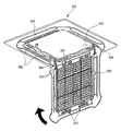
- FIG. 1 is a perspective view illustrating an exterior of an indoor device for a cassette type air conditioner according to the related art.
- an indoor unit or device 1 may be maintained in a state in which an upper portion of the indoor device 1 is fixed to an inside of a ceiling and hung on the ceiling, and a bottom surface is exposed to a lower side of the ceiling to suction indoor air and then to discharge the suctioned air into the indoor space.
- the indoor device 1 as most of the main body is disposed in the ceiling, only a panel 10 and suction grill 20 may be shown when a user looks up toward the ceiling.
- the panel 10 may define an exterior edge of the bottom surface of the indoor device 1 .
- a suction hole 11 which may be provided in a square shape, may be defined in a central portion of the panel 10 to guide introduction of the indoor air into the indoor device 1 .
- a plurality of discharge holes 12 which may be provided to guide the air so that the air conditioned in the indoor device 1 may be discharged again into the indoor space, may be defined outside of the suction hole 11 .
- a vane 13 to adjust a flow direction of the discharged air may be rotatably disposed in each discharge hole 12 .
- the suction grill 20 which may have an approximately square plate shape and in which a plurality of hole through which air passes may be defined may be mounted on the central portion of the front panel 10 , that is, inside the suction hole 11 .
- the suction grill 20 may be configured to filter foreign substances contained in the air introduced into the indoor device 1 through the suction hole 11 .
- the suction grill 20 may have a size and shape that corresponds to a size and shape of the suction hole 11 .
- An air filter 30 may be disposed above the suction grill 20 .
- the air filter 30 may be separably mounted on the suction grill 20 so as to provide for easy cleaning where foreign substances collect on the air filter 30 when the indoor device 1 is used for a long period of time. Also, the suction grill 20 may be selectively opened so that the air filter 30 may be easily separated therefrom.
- the suction grill 20 may be rotatably coupled to an end or edge of the panel 10 .
- a first end of the suction grill 20 and an inner surface of the suction hole 11 may be coupled to each other by a hinge 21 .
- the suction grill 21 may rotate downward with respect to the hinge 21 to selectively open an inside of the indoor device 1 , as illustrated in FIG. 1 .
- a switching button 14 which may be manipulated by a user when the suction grill 20 is opened or closed, may be disposed on a surface of the front panel 10 .
- the switching button 14 may interfere with a second end of the suction grill 20 by an elastic restoring force thereof to prevent the suction grill 20 from rotating.
- the switching button 14 is pushed, the interference with the second end of the suction grill 20 may be released, and thus, the suction grill 20 may rotatable with respect to the hinge 21 .
- the suction grill 20 may have a structure in which the first and second ends of the suction grill 20 are supported by the switching button 14 and the hinge 21 . Thus, the suction grill 20 may be restricted in a closed state.
- the suction grill 20 when the indoor device 1 increases in size, the suction grill 20 may also increase in size. In this case, if only the first and second ends of the suction grill 20 are supported, sides of the suction grill 20 may droop down. Also, even if the indoor device 1 itself is not changed in size, when the suction grill 20 further increases in size, the above-described limitation may occur.
- FIG. 1 is a perspective view of an indoor device for a cassette type air conditioner according to a related art
- FIG. 2 is a schematic cutoff perspective view of an indoor device for a cassette type air conditioner according to an embodiment
- FIG. 3 is a bottom view of the indoor device for a cassette type air conditioner of FIG. 2 ;
- FIG. 4 is an exploded perspective view illustrating a main portion of the indoor device for a cassette type air conditioner of FIG. 2 ;
- FIG. 5 is a view illustrating a state in which a panel and a suction grill of the indoor device for a cassette type air conditioner of FIG. 2 are coupled to each other according to embodiments;
- FIG. 6 is a partial enlarged view illustrating a state in which a coupling member of the indoor device for a cassette type air conditioner of FIG. 2 is coupled;
- FIG. 7 is a view illustrating a state in which the panel and the suction grill of the indoor device for a cassette type air conditioner of FIG. 2 are separated from each other;
- FIG. 8 is a perspective view illustrating an inner side surface of the suction grill according to embodiments.
- FIG. 9 is a partial cross-sectional view of the suction grill of FIG. 8 , taken along line IX-IX′ of FIG. 8 ;
- FIG. 10 is a cross-sectional view of the indoor device for a cassette type air conditioner according to embodiment
- FIG. 11 is a perspective view illustrating a state in which the suction grill is opened according to embodiments.
- FIG. 12 is a schematic perspective view illustrating an air flow in the panel and the suction grill according to embodiments.
- FIG. 13 is a partial perspective view of an air discharge structure in a discharge hole according to embodiments.
- FIG. 2 is a schematic cutoff perspective view of an indoor device for cassette type air conditioner according to an embodiment.
- an indoor unit or device 100 for an air conditioner (hereinafter, referred to as an “indoor device”) according to embodiments may include a cabinet 110 inserted into a ceiling in an indoor space, and a panel 200 and suction grill 300 , which may be disposed on a lower end of the cabinet 110 to define an exterior of a bottom surface of the indoor device 100 and may be exposed in the ceiling when the indoor device 100 is installed.
- a heat exchanger 140 that heat-exchanges with suctioned air, a blower fan 120 to forcibly suction in and discharge indoor air, and an air guide 130 having a bellmouth shape to guide the suctioned air toward the blower fan 120 may be provided in the cabinet 110 .
- the panel 200 may be mounted on the lower end of the cabinet 110 and have an approximately rectangular shape when viewed from a lower side thereof. Also, the panel 200 may protrude outward from the lower end of the cabinet 110 so that a circumferential portion of the panel 200 may be in contact with the ceiling.
- a discharge hole 210 may be defined at a position corresponding to each side of the panel 200 .
- Each discharge hole 210 may be defined along a longitudinal direction of each side of the panel 200 .
- Each discharge hole 210 may be opened or closed by a vane 220 mounted on the panel 200 .
- the suction grill 300 may be mounted on or at a central portion of the panel 200 .
- the suction grill 300 may define an exterior of a bottom surface of the indoor device 100 .
- the suction grill 300 may provide a passage for air introduced into the indoor device 100 .
- At least a portion of the suction grill 300 may have a grill or lattice shape so that the indoor air may be smoothly introduced.
- FIG. 3 is a bottom view of the indoor device for a cassette type air conditioner of FIG. 2 .
- FIG. 4 is an exploded perspective view of a main portion of the indoor device for a cassette type air conditioner of FIG. 2 .
- FIG. 5 is a view illustrating a state in which the panel and the suction grill of the indoor device for a cassette type air conditioner of FIG. 2 are coupled to each other.
- FIG. 6 is a partial enlarged view illustrating of a state in which a coupling member of the indoor device for a cassette type air conditioner of FIG. 2 is coupled.
- FIG. 7 is a view illustrating a state in which the panel and the suction grill of the indoor device for a cassette type air conditioner of FIG. 2 are separated from each other.
- the panel 200 may have an approximately rectangular plate shape.
- a suction hole 230 may be provided in a central portion of the panel 200 .
- the suction hole 230 may be configured to suction in the indoor air.
- the suction hole 230 may have a square shape and a size slightly less than a size of the suction grill 300 .
- the discharge hole(s) 210 may be defined outside of the suction hole 230 .
- the discharge hole(s) 210 may be provided in each of four sides. Both ends of each discharge hole 210 may have a curve shape having a width that gradually decreases towards ends thereof.
- a grill seat 232 may be disposed outside of the suction hole 230 .
- the grill seat 232 may be stepped to support the suction grill 300 .
- a panel-side mount 260 on which a connection member 400 that will be discussed hereinbelow may be mounted may be disposed on the grill seat 232 .
- a circumference of the grill seat 232 may have a close loop shape that generally defines an outer line of each discharge hole 210 .
- a rounded groove 234 may be defined around the grill seat 232 in a state in which the suction grill 300 is mounted.
- the rounded groove 234 may have a square shape having four rounded edges.
- the four rounded edges of the rounded groove 234 may define a line corresponding to an outer line of the suction grill 300 , so that vanes 220 of the discharge hole(s) 210 , the suction grill 300 , and the panel 200 may provide a sense of unity on the whole.
- the rounded groove 234 may have a predetermined rounded or inclined section so that discharged air does not flow along the panel 200 , thereby preventing the ceiling from being wetted or contaminated by air discharged from the discharge hole(s) 210 .
- the discharge hole(s) 210 may be opened or closed by the vane(s) 220 .
- a motor may be disposed on an end of each vane 220 .
- the vane 220 may be rotated by the motor to adjust a flow direction of the discharged air.
- Each vane 220 may have a shape corresponding to a shape of a respective discharge hole 210 to cover the discharge hole 210 . Also, each of the vane 220 may have a width that gradually decreases towards ends thereof, similar to the discharge hole 210 . When the vane 220 is closed, an outer edge of the vane 220 may extend along the rounded groove 234 to contact the panel 200 , and an inner edge of the vane 220 may contact a concave portion 310 of the suction grill 360 .
- An inspection hole 240 may be formed in each of the four edges of the panel 200 .
- the inspection hole 240 may provide a space to fix and install the panel 200 .
- the inspection hole 240 may be opened or closed by a corner cover 242 so as to receive service to electric components mounted on a back surface of the panel 200 or confirm an operation of the indoor device 100 .
- An inspection hole 240 and a corner cover 242 may be disposed on each of the four edges of the panel 200 or be disposed on at least one of the four edges.
- An end of the corner cover 242 may be disposed to face an end of protrusion 320 of the suction grill 300 with respect to a boundary of the rounded groove 234 .
- Each corner cover 242 and protrusion 320 may have lines corresponding to the rounded groove 234 to provide a three-dimensional effect on the whole.
- a separate panel bracket 236 may be mounted on the grill seat 232 of the panel 200 .
- the panel bracket 236 may be configured to reinforce the grill seat 232 and stably support components to mount or open/close the suction grill 300 mounted on the grill seat 232 .
- the panel bracket 236 may not be provided, but rather, the grill seat 232 and the panel bracket 236 may be integrated with each other to allow the grill seat 232 to perform the function of the panel bracket 236 .
- the panel bracket 236 may have a square frame shape. Also, a central portion of the panel bracket 236 may be opened in a shape corresponding to a shape of the suction hole 230 .
- the panel bracket 236 may be fixed so that a switching member 340 and a fixing member 330 , which will be described hereinbelow, may be hooked in a state in which the panel bracket 236 is mounted on the panel 200 to maintain a closed state of the suction grill 300 .
- the panel bracket 236 may be formed of a material having a high strength to prevent the panel bracket 236 from being deformed or damaged.
- the panel bracket 236 may be formed of a material different from that of the panel 200 .
- the panel bracket 236 may be formed of a metal material and mounted on an inner side surface of the panel 200 .
- a coupling portion 237 to which a suction grill restricter 390 may be coupled, may be disposed on each of both sides of the panel bracket 236 .
- the coupling portion 237 and the suction grill restrictor 390 may be disposed on both lateral sides of the panel bracket 236 so that the suction grill 300 may be fixed in four directions by the switching member 340 , the fixing member 330 , and the suction grill restricter 390 .
- the suction grill restricter 390 may be disposed at a center of the suction grill 300 in a front to rear direction so that both ends of the suction grill 300 do not droop down, but rather, are fixed in a state in which the suction grill restricter 390 is coupled to the panel bracket 236 . That is, front and rear ends of the suction grill 300 may be maintained in a fixed state by the switching member 340 and the fixing member 330 , and both ends of the suction grill 300 may be fixed by the suction grill restricter 390 .
- each of the switching member 340 , the fixing member 330 , and the suction grill restrictor 390 may be coupled to the panel 200 to correspond to the panel 200 . Also, in some cases, at least one of the switching member 340 , the fixing member 330 , or the suction grill restrictor 390 may be restricted with the panel bracket 236 , and the rest may be restricted with the panel 200 .
- the suction grill 300 may be mounted on the grill seat 232 . In a state in which the suction grill 300 is mounted, a bottom surface of the panel 200 and a bottom surface of the suction grill 300 may be disposed on a same plane to provide a sense of unity.
- the concave portion 310 may be defined in each of the sides of the suction grill 300 .
- the concave portion 310 may be disposed at a same position as an inner line of the discharge hole 210 .
- an inner line of the discharge hole 210 and the concave portion 310 may have a same shape. That is, the concave portion 310 may have rounded ends or edges.
- the concave portion 310 may have a curvature corresponding to the shapes of the discharge hole 210 and the vane 220 .
- an inner line of the vane 220 and an end or edge of the suction grill 300 may be adjacent to each other at the same distance.
- the suction grill 300 and the panel 200 may provide a sense of unity.
- the protrusion 320 may be disposed on each of the four edges of the suction grill 300 . Each protrusion 320 may further protrude from the concave portion 310 to define a region between the concave portions 310 . Each protrusion 320 may be disposed between the discharge holes 210 when the suction grill 300 is mounted. Each protrusion 320 may have an end that is rounded at a same curvature as that of the rounded groove 234 . Thus, in a state in which the suction grill 300 is mounted, a circumference defined by the suction grill 300 and the vane 220 may have a same shape as the rounded groove 234 .
- the protrusion 320 may have a same width as the corner cover 242 .
- a side groove 238 defined along the protrusion 320 may extend up to an end or edge of the panel 200 along both sides of the corner cover 242 . Also, the side groove 238 may be connected to the concave portion 310 of the suction grill 300 and the inner line of the vane 220 .
- the rounded grooves 234 may be defined in a center, and the side groove 238 may be defined in each of four sides.
- the shapes of the suction grill 300 , the discharge hole 210 , and the vane 220 may be defined by the rounded groove 234 and the side grooves 238 .
- FIG. 8 is a perspective view illustrating an inner side surface of the suction grill according to embodiments.
- a grill-side mount 370 on which the connection member 400 may be mounted, may be disposed on each of both lateral sides of a top surface of the suction grill 300 .
- the grill-side mount 370 may be disposed outside of a suction portion 350 , which will be described hereinbelow. That is, a pair of ribs may extend upward from the grill-side mount 370 to allow the connection member 400 to be rotatably fixed thereto.
- a fixing member 330 to fix the suction grill 300 and a switching member 340 to selectively restrict the suction grill 300 may be disposed on front and rear ends of a top surface of the suction grill 300 , respectively.
- Each fixing member 330 may be mounted on or at a rear side of the suction grill 300 as a separate member.
- Each fixing member 330 may include a pair of protruding fixed pieces 332 to be fixed to the panel 200 or the panel bracket 236 , and a coupling plate 334 to connect the pair of fixed pieces 332 to each other and to the suction grill 300 .
- the pair of fixed pieces 332 may be inclined upward.
- the fixed pieces 332 may be inserted into one side of the panel 200 to fix a rear end of the suction grill 300 to the panel 200 .
- the suction grill 300 is pulled forward, the rear end of the suction grill 300 may be separated from the panel 200 .
- a pair of the fixing members 330 may be provided at both lateral sides of the suction grill 300 .
- the fixing members 330 may be integrated with the suction grill 300 .
- a fixing member insertion portion, in which the fixing member 330 may be inserted, may be defined in the panel 200 or the panel bracket 236 to correspond to each fixing member 330 .
- Each switching member 340 may be restricted against the panel 200 or the panel bracket 236 so that a front end of the suction grill 300 may be fixed in a state in which the fixing member 330 is inserted into the panel 200 or the panel bracket 236 . That is, the switching member 340 may be selectively restricted according to a user's manipulation.
- each switching member 340 may be disposed on a front portion of the suction grill 300 . Also, a pair of switching members 340 may be provided with a distance therebetween that corresponds to the fixing member 330 . Also, each switching member 340 may be configured to selectively restrict the panel 200 and the suction grill 300 by elasticity when manipulated by a user. Each switching member 340 may be configured to be manipulated by a user when the suction grill 300 is separated or mounted. Each switching member 340 may have one side exposed to a bottom surface of the suction grill 300 so as to be manipulated. The elasticity to operate the switching member 340 may be provided by the switching member 340 itself or a separate elastic member.
- the switching member 340 may include a fixed portion 341 fixed to the suction grill 300 , a manipulation portion 345 that extends from the fixed portion 342 to move the fixed portion 341 by a user's manipulation, and a plate-shaped elastic part 344 that extends to each of both sides of the manipulation portion 345 to provide an elastic force when the manipulation portion 345 is manipulated.
- a guide hole 342 having a long hole shape may be defined in a center of the fixed portion 341 .
- a guide protrusion 301 that protrudes from the suction grill 300 may be inserted into the guide hole 342 .
- the fixed portion 341 may be moved in forward and backward directions by the guide protrusion 301 and the guide hole 342 .
- An insertion piece 343 that extends in a direction opposite to an extending direction of the manipulation portion 345 may be disposed on each of first and second ends of the fixed portion 341 .
- the insertion piece 343 may be inserted into the panel 200 or the panel bracket 236 when the fixed portion 341 moves to maintain a state in which the suction grill 300 is restricted and mounted on the suction grill 300 and the panel 200 by the switching member 340 .
- An insertion piece guide 302 to guide movement of the insertion piece 343 may be disposed on the suction grill 300 .
- the insertion piece 343 may pass through the insertion piece guide 302 provided on the suction grill 300 .
- the insertion piece guide 302 may support the insertion piece 343 .
- an end of the insertion piece 343 may pass through the insertion piece guide 302 and then be hooked and restricted by the panel 200 or the panel bracket 236 so that the suction grill 300 may be fixed in a closed state.
- the insertion piece guide 302 may guide movement of the insertion piece 343 so that the insertion piece 343 moves in an accurate direction as well as prevents the insertion piece 343 from drooping down.
- the elastic portion 344 may have a plate shape, which may be inclined or curved in a backward direction and extend to both lateral sides.
- the elastic portion 344 may contact a support wall 303 that protrudes from the upper surface of the suction grill 300 .
- the fixed portion 341 may be maintained in a state in which it moves in a forward direction when the manipulation portion 345 is not manipulated.
- the insertion piece 343 may be restricted with the panel 200 or the panel bracket 236 , and thus, the suction grill 300 may be maintained in a mounted state thereof.
- the elastic portion 344 may be elastically deformed, and the fixed portion 341 may be moved in a backward direction. As a result, restriction of the insertion piece 343 may be released to open the suction grill 300 .
- the manipulation portion 345 may pass through the support wall 303 and then be bent at an end of the fixed portion 341 .
- the manipulation portion 345 may have an end that passes through the suction grill 300 and may be exposed to the outside so that a user may manipulate the manipulation portion 345 .
- the manipulation portion 345 may be exposed between the plurality of grills 360 of the suction grill 300 . In this case, a user may insert a finger thereof into a suction hole 352 between the plurality of grills 360 to manipulate the manipulation portion 345 .
- the suction grill restrictor 390 may be disposed on each of both sides of the suction hole 230 .
- the suction grill restrictor 390 may have a hook shape.
- the suction grill restrictor 390 may be disposed at a position such that the suction grill restrictor 390 may be coupled to the coupling portion 237 disposed on the panel bracket 236 .
- the suction grill restrictor 390 may be disposed on a filter guide 380 provided on each of both sides of the suction hole 230 .
- the filter guide 380 may extend in forward and rearward directions.
- the filter guide 380 may be configured to mount a filter case 250 or an air filter on the upper surface of the suction grill 300 .
- the filter guide 380 may be provided as a separate member, and then, may be mounted on the suction grill 300 .
- the filter guide 380 may be configured so that the filter case 250 or the air filter may be slidably coupled or detachably coupled thereto. For this, the filter case 250 may be slidably inserted into or vertically coupled to inner side surfaces of a pair of filter guides 380 .
- the suction grill restrictor 390 may protrude upward from a central portion of the filter guide 380 . That is, the suction grill restrictor 390 may be disposed at a center in a front to rear direction to restrict central portions of both sides of the suction grill 300 when coupled to the coupling portion 237 to prevent the suction grill 300 from drooping down, thereby stably supporting the suction grill 300 .
- the suction grill restrictor 390 may include an extension 392 that extends upward from the filter guide 380 , and a hook 394 having a hook shape and disposed on an end of the extension 392 .
- the hook 394 may be hooked with the coupling portion 237 , which may be recessed outward in a state in which the suction grill 300 is mounted.
- a top surface of the hook 394 may be inclined.
- the suction grill restrictor 390 moves downward from an upper side, the coupling portion 237 and an inclined surface of the hook 394 may contact each other, and the extension 392 may be deformed inwardly. Then, when the inclined surface of the hook 394 passes through the coupling portion 237 , the hook 394 may be hooked with the coupling portion 237 .
- An air filter (not shown) to purify air may be disposed above upper surface of the suction grill 300 .
- the air filter may be detachably mounted on or to the filter case 250 .
- the air filter to filter foreign substances and physically or chemically purify suctioned air may be disposed within the filter case 250 .
- the air filter may be separated from the filter case 250 , and then, may be replaced after a predetermined time or usable time has elapsed.
- a suction portion 350 which may have a lattice shape, may be disposed on or at the center of the suction grill 300 .
- the suction portion 350 may be disposed inside the suction hole 230 of the panel 200 to allow the suctioned air to fully flow into the cabinet 111 through the panel 200 .
- FIG. 9 is a partial cross-sectional view illustrating the suction grill of FIG. 8 , taken along line IX-IX′ of FIG. 8 .
- the suction portion 350 of the suction grill 300 may have a lattice shape due to the plurality of grills 360 , which may be disposed to cross each other in horizontal and vertical directions.
- Suction holes 352 through which air may be suctioned, may be successively defined between the plurality of grills 360 .
- each of the plurality of grills 360 may have a cross-section having a shape that gradually decreases in width in a direction toward a bottom surface of the suction grill 300 , with reference to FIG. 9 .
- air suctioned through the suction holes 352 may smoothly flow upward without colliding with each other after passing through the plurality of grills 360 .
- Each of the plurality of grills 360 may have a downwardly recessed shape with an opened top surface.
- Each grill 360 may have a predetermined space therein. Thus, dust or foreign substances generated above the suction grill 300 may drop and be collected into the space.
- the grill 360 may include an inclination portion 361 at a lower portion thereof and a vertical portion 362 that vertically extends upward from an upper end of the inclination portion 361 .
- the inclination portion 361 may be tapered downward to form both inclined side surfaces.
- each suction hole 352 may have a wide lower end and a width that gradually decreases as it extends upward.
- the vertical portion 362 may extend upward in a direction substantially perpendicular to a bottom surface of the suction grill 300 from an upper end of the inclination portion 361 .
- the inclination portion 361 may have a vertical length D1 less than a length D2 of the vertical portion 362 .
- the inclination portion 361 may have an angle so that the vertical portion 361 has an upper distance D3 greater by at least two times than the length D2 of the vertical portion 362 when comparing the upper end of the inclination portion 361 , that is, a horizontal distance D3 of the vertical portion 362 to the horizontal length D2 of the vertical portion 361 .
- the air passing through the suction hole 352 may be suctioned in a state in which the air is divided at the upper end of the suction holes 352 .
- the air suctioned through the suction holes 352 may not cause noise due to collision as the air passes through the suction holes 352 .
- the suction grill 300 may be configured to open or close the panel 200 according to a user's manipulation.
- the suction grill 300 may be connected to the panel 200 by the connection member 400 , which connects the suction grill 300 to the panel 200 .
- the suction grill 300 may be slidably movable or rotatable.
- connection member 400 and components to mount the connection member 400 will be described in detail hereinbelow.
- FIG. 10 is a cross-sectional view of the indoor device for a cassette type air conditioner according to embodiments.
- FIG. 11 is a perspective view illustrating a state in which the suction grill is opened according to embodiments.
- connection member 400 may have both ends respectively mounted on the panel 200 and the suction grill 300 .
- a pair of the connection member 400 may be provided on or at both lateral sides to connect the suction grill 300 to the panel 200 .
- the grill-side mount 370 may be disposed on each of both lateral sides of the suction grill 300
- the panel-side mount 260 may be disposed on the panel 200 .
- the grill-side mount 370 may be coupled to a rotation coupling portion 422 disposed on a lower end of the connection member 400 .
- the grill-side mount 370 may be provided as a pair of protruding plates so that the rotation coupling portion 422 may be rotatably coupled thereto. That is, the rotation coupling portion 422 may be inserted between the grill-side mounts 370 . Both sides of the rotation coupling portion 422 may be rotatably coupled to the grill-side mount 370 .
- the panel-side mount 260 may be disposed on each of both lateral sides of the panel 200 so that an upper end of the connection member 400 may be mounted thereon.
- a plurality of panel-side mounts 260 may be provided so that the panel-side mounts 260 may be mounted regardless of a mounting direction of the suction grill 300 . That is, the panel-side mount 260 may be disposed at a position spaced apart from each of both lateral sides of the panel 200 .
- four panel-side mounts 260 may be provided.
- the mounting direction of the suction grill 300 may be selected to determine an opening direction of the suction grill 300 . That is, when the connection member 400 is mounted on the panel-side mount 260 disposed on a front portion of the panel 200 , the suction grill 300 may be opened while rotating using the front portion of the panel 200 as an axis. On the other hand, when the connection member 400 is mounted on the panel-side mount 250 disposed on a rear portion of the panel 200 , the suction grill 300 may be opened while rotating using the rear portion of the panel 200 as an axis.
- the panel-side mounts 260 disposed on the panel 200 may have a same fundamental structure and shape.
- Each panel-side mount 260 may include an edge to define a space in which the connection member 400 may be accommodated, a slot 262 inside the edge 261 , and restricters 265 and 266 that protrudes from both lateral sides of the slot 262 to selectively restrict sliding movement of the connection member 400 .
- the edge 261 may extend upward to define a space in which an end of the connection member 400 may be accommodated and slidable.
- the edge 261 may have a rectangular shape. That is, the edge 261 may extend along one side of the grill seat 232 .
- the slot 262 may be defined in a space defined by the edge 261 and opened from a first end of the slot 262 up to a second end of the slot 262 .
- the slot 262 may have a width less than a width of the upper end of the connection member 400 .
- the upper end of the connection member 400 may protrude from both sides of the slot 262 .
- a lower end of the slot 262 may have a width corresponding to an upper end of the connection member 400 or be opened to have an inner diameter greater than the width of the connection member 400 so that the connection member 400 may be inserted into the slot 262 .
- the connection member 400 when the connection member 400 is mounted, the upper end of the connection member 400 may be inserted through the lower end of the slot 262 .
- the connection member 400 In a state in which the connection member 400 is inserted into the slot 262 , the connection member 400 may be movable along the slot 262 .
- a bottom surface 263 may be disposed on both lateral sides of the slot 262 to contact a contact 412 disposed on each of both lateral sides of the upper end of the connection member 400 .
- the contact 412 may move along the bottom surface 263 when the connection member 400 moves.
- the bottom surface 263 may be inclined downward so that the contact 412 may be smoothly slidable in contact with the bottom surface 263 .
- a first restricter 265 may be disposed on an end of the slot 262 .
- the first restricter 265 may protrude upward to prevent the connection member 400 as it moves along the slot 262 from being inserted into the end of the slot 262 . That is, the first restricter 262 may protrude upward to prevent the contact 412 from moving toward the lower end of the slot 262 .
- a second restricter 266 may be further disposed on one side of the bottom surface 263 .
- the second restricter 266 may protrude upward from the bottom surface 263 corresponding to the contact 412 in a state in which the suction grill 300 is closed.
- movement of the contact 412 in a direction in which the suction grill 300 is opened may be restricted.
- the second restricter 266 may have an inclined surface 267 so that the second restricter 266 has a height that gradually increases away from the first restricter 265 .
- a vertical surface 268 that extends substantially perpendicular to the bottom surface 263 may be disposed on a highest end of the inclined surface 267 .
- the contact 412 of the connection member 400 may move away from the first restricter 265 .
- the contact 412 of the connection member 400 may slidably move over the inclined surface 267 of the second restricter 266 .
- the contact 412 of the connection member 400 may contact the vertical surface 268 of the second restricter 266 to restrict random slidable movement of the connection member 40 .
- the inclined surface 267 and the vertical surface 268 may be disposed so that they have surfaces that cross each other to more effectively perform sliding movement of the contact 412 and the restrict the contact 412 .
- connection member 400 may have a bar shape having a predetermined length.
- the connection member 400 may have a sufficiently long length to maintain a sufficient distance so that the end of the suction grill 300 does not interfere with the panel 200 when the suction grill 300 is fully opened.
- connection member 400 may include an upper bent portion 410 , a lower bent portion 420 , and an intermediate connection portion 430 .
- the upper bent portion 410 may be bent upward (when viewed in FIG. 10 ) with respect to the intermediate connection portion 430 , the lower bent portion 420 may be bent downward in a direction opposite to the upper bent portion 410 , and the intermediate connection portion 430 may connect the upper bent portion 410 to the lower bent portion 420 .
- the upper bent portion 410 and the lower bent portion 420 may extend at an incline.
- the upper bent portion 410 may have an inclination greater than of the lower bent portion 420 .
- the contact 412 may be disposed on or at an upper end of the upper bent portion 410 .
- the contact 412 may be disposed on both lateral sides of the upper end of the upper bent portion 410 to contact the bottom surface 263 of the panel-side mount 260 .
- the contact 412 may have a roller shape, which is easily slidable. Further, the contact 412 may be rotatably mounted on the upper bent portion 410 .
- the contact 412 may be mounted to protrude from both sides of the upper bent portion 410 and have a width greater than a width of each of the upper bent portion 410 , the intermediate connection portion 430 , and the lower bent portion 420 . Thus, when the connection member 400 slidably moves along the slot 262 , the contact portion 412 may contact the bottom surface 263 of each of both sides of the slot 262 .
- the contact 412 may have a diameter greater than a height of the vertical surface 268 of the second restricter 266 . Thus, when a user manipulates the suction grill 300 to open the suction grill 300 , the contact part 412 may move over the vertical surface 268 .
- the lower bent portion 420 may extend to a lower end of the intermediate connection portion 430 . That is, a pair of lateral sides of the lower bent portion 420 may extend so that central portions of the lower bent portion 420 may extend away from each other. Also, the rotation coupling portion 422 may be disposed on each of both sides of the lower end of the lower bent portion 420 . The rotation coupling portion 422 may be rotatably shaft-coupled to the grill-side mount 370 disposed on the suction grill 300 . Thus, when the suction grill 300 is opened, the suction grill 300 may be rotatable using the rotation coupling portion 422 as an axis.
- the bottom surface of the suction grill 300 and a circumference of the bottom surface of the panel 200 may be disposed on a same plane so that the suction grill 300 and the panel 200 have a sense of unity.
- connection member 400 may extend substantially parallel to the suction grill 300 , and the contact 412 may be in contact with the vertical surface 268 of the second restricter 266 . Thus, the contact 412 may be restricted in movement in one direction by the vertical surface 268 .
- the fixing member 330 mounted on the suction grill 300 may be inserted into the panel 200 or the panel bracket 236 .
- a first end of the suction grill 300 may be fixed, and a second end of the suction grill 300 may be restricted with the panel 200 or the panel bracket 236 by the switching member 340 .
- the suction grill restrictor 390 may be fixed to the coupling portion 237 of the panel bracket 236 to restrict both ends of the suction grill 300 .
- the suction grill 300 may be maintained in a state in which the suction grill 300 is fixed and mounted on the panel 200 .
- the suction grill 300 may be fixed in four directions, that is, four sides of the suction grill 300 may be fixed.
- the switching member 340 of the fixing member 330 may be provided as a pair, and the suction grill restrictor 390 may be disposed at a center in the front to rear direction to prevent the suction grill 300 from drooping downward even though the suction grill 300 has a large size, thereby stably mounting the suction grill 300 .
- the indoor device 100 may operate to suction in the indoor air through the suction portion 350 of the suction grill 300 . Then, the suctioned air may be heat-exchanged within the indoor device 100 and discharged into the indoor space through the discharge hole(s) 210 .
- the suction grill 300 will have to be opened.
- the switching member 340 may be manipulated first to allow restriction of the second end of the suction grill 300 to be released from the panel 200 .
- the switching member 340 may be manipulated to release the restriction of the first end of the suction grill 300 and then pull the suction grill 300 downward.
- the suction grill restricter 390 may be separated from the coupling portion 237 , and both ends of the suction grill 300 may also be separated from the panel 200 .
- the suction grill 300 when the suction grill 300 is pulled forward to allow the contact 412 to move away from the second restricter 266 , the suction grill 300 may slightly move forward to separate the fixing member 330 from the panel 200 . That is, the restriction between the suction grill 300 and the panel 200 may be completely released, and thus, the suction grill 300 may be movable forward or backward.
- the contact 412 may slidably move over the vertical surface 268 of the second restricter 266 . Also, the contact 412 may be smoothly slidable along the inclination of the bottom surface 263 . The contact 412 may be smoothly slidable to the first restricter 265 by a weight of the suction grill 300 . Simultaneously, the suction grill 300 may be smoothly rotated and then be opened due to the position of the grill seat 232 disposed biased to one side of the suction grill 300 .
- connection member 400 may slidably move to provide a sufficient gap between the panel 200 and the suction grill 300 .
- the suction grill 300 rotates to open, the suction grill 300 and the panel 200 may not interfere with each other.
- the protrusion 320 disposed on an edge of the suction grill 300 may cover the panel 200 .
- the panel 200 and the suction grill 300 may be spaced apart from each other by movement of the connection member 400 as described above to open the suction grill 300 without interfering with the protrusion 320 even though the suction grill 300 rotates.
- the suction grill 300 may smoothly slide and rotate just when the contact 412 of the connection member 400 is over the first restricter 265 by the coupling relationship between the connection member 400 , the panel 200 , and the suction grill 300 .
- the front end of the suction grill faces a lower side, and thus, a back surface of the suction grill 300 may be fully exposed forward.
- internal cleaning and service operations of the indoor device 100 may be performed, and also, replacement of the air filter and the cleaning of the suction grill 300 may be easily performed.
- a user may detach the suction grill 300 to separate the suction grill 300 from the panel 200 .
- the user may lift the suction grill 300 upward in a state in which the contact 412 is in contact with the first restricter 265 to allow the contact 412 to be withdrawn through the opened portion of the lower end of the slot 262 over the first restricter 262 , thereby separating the connection member 400 from the panel-side mount 260 .
- the above-described processes may be reversely performed to insert the connection member 400 into the panel-side mount 260 .
- the suction grill 300 may rotate and slide to allow the contact 412 to contact the vertical surface 268 of the second restricter 266 .
- the suction grill restricter 390 may be coupled to the coupling portion 237 , and the fixing member 330 and the switching member 340 may restrict the panel 200 to maintain a state in which the suction grill 300 is closed.
- the front and rear ends and both lateral ends of the suction grill 300 may be restricted with the panel 200 to prevent each of the ends of the suction grill 300 from drooping downward, thereby maintaining a stably fixed state of the suction grill 300 .
- FIG. 12 is a schematic perspective view illustrating an air flow in the panel and the suction grill according to embodiments.
- FIG. 13 is a partial perspective view of an air discharge structure in a discharge hole according to embodiments.
- indoor air may be suctioned into the indoor device 100 through the suction grill 300 . Also, the air may be heat-exchanged within the indoor device 100 , and then discharged to the outside through the plurality of discharge holes 210 .
- discharged air may be directed in a flow direction according to a rotating direction of the vane 220 .
- the air may be discharged outward from each of the discharge holes 210 .
- An outer line of the discharge hole(s) 210 may be defined by the rounded groove 234 .
- the rounded groove 234 may have a rounded section. As illustrated in FIG. 15 , the discharged air may not flow along an outer surface of the panel 200 , but rather, be discharged into the indoor space. Thus, the discharged air may be supplied into the indoor space without contaminating the panel 200 outside of the discharge hole(s) 210 or the ceiling surface.
- Both ends of each discharge hole 210 of the panel 200 may gradually decrease in width outward and be rounded to forma a tapered end of the panel 200 .
- a guide member defining an inner surface of the discharge hole 210 may be inclinedly disposed. More particularly, in a case of both ends of the discharge hole 210 , the guide member may be rounded toward both ends of the discharge hole 210 .
- discharged air may be concentrated as a flow of air discharged from both ends of the discharge hole 210 in a central direction to prevent dew condensation from occurring on ends of the discharge hole 210 and an end of the vane 220 .
- a suction grill may be mounted to cover a panel. More particularly, the suction grill may extend up to discharge holes of the panel to form as inner line of the discharge holes, thereby providing an elegant exterior. Also, an outer line of the discharge holes and a protrusion of the suction grill may form one closed loop by the rounded groove to minimize lines generated by connected portions between components, thereby further providing an elegant exterior.
- the grill restriction member to fix the suction grill to the panel may be further provided to prevent a central portion of the suction grill having a large size from drooping downward.
- the suction grill y increase in size to more simplify the exterior of the indoor device.
- the grill restriction member may prevent air from leaking between the suction grill and the panel. Thus, it may prevent dew condensation from occurring between gaps in the suction grill or the panel, and also prevent noise from occurring due to the introduction of the air into the gaps.
- the switching member and the grill restriction member when the switching member is manipulated, it may prevent the suction grill from drooping downward or rotating. Also, when the suction grill is closed, as the switching member may be manipulated in a state in which the suction grill may be primarily fixed, convenience in use may be improved.
- Embodiments disclosed herein provide an indoor unit or device for a cassette type air conditioner including a grill restriction member configured to couple a suction grill to a panel so as to prevent an outer end of the suction grill from drooping downward.
- Embodiments disclosed herein provide an indoor unit or device for a cassette type air conditioner that may include a cabinet, in which a heat exchanger and a blower may be mounted, the cabinet being installed on or in a ceiling in an inner or indoor space; a panel that defines a bottom surface of the cabinet, the panel having a suction hole and a discharge hole; a suction grill mounted to cover the suction hole of the panel; a fixing member disposed on one side of the suction grill, the fixing member being fixed to one side of the panel to restrict one end of the suction grill; a switching member disposed on the other side of the suction grill facing the fixing member, the switching member being selectively fixed to the one side of the panel to restrict the other end of the suction grill; and a grill restriction member disposed on each of both sides of the suction grill between the fixing member and the switching member, the grill restriction member being coupled to each of both sides of the panel to restrict both ends of the suction grill.
- Each of the fixing member and the switching member may be provided in plurality, and
- At least one portion of the switching member may be exposed through a suction hole defined in a lattice shape in the suction grill to allow a user to perform an opening/closing operation.
- the fixing member may include a fixed piece that extends outwardly and is inserted into one side of the panel.
- a panel bracket mounted along a circumference of the suction hole to allow the grill restriction member to be restricted may be disposed on the panel.
- the panel bracket may include an inwardly recessed coupling part or portion, on which the grill restriction member having a hook shape may be hooked and restricted.
- Each of the coupling part and the grill restriction member may be disposed at a middle point in a longitudinal direction of each of both sides of the suction grill.
- the grill restriction member may include an extension part or extension that extends upward from the suction grill, and a hook part or hook that protrudes laterally from an end of the extension part.
- the hook part may be hooked and restricted with the panel, and the hook part may have an inclined top surface.
- a connection member may be disposed between the panel and the suction grill.
- the suction grill may be rotated by the connection member to open the suction hole.
- a panel-side mount part or mount, on which the connection member may be slidably mounted, may be disposed on each of both sides of the panel, and a grill-side mount part or mount, to which the connection member may be rotatably coupled, may be disposed on each of both sides of the suction grill.
- the panel-side mount part may be provided in a pair on left and right or lateral sides of the panel, the pair of panel-side mount part may be symmetrical to each other, and the connection member may be selectively mounted on one of the panel-side mount parts according to an opened direction of the suction grill.
- a filter guide on which a filter case to accommodate an air filter may be fixed and mounted, may be disposed on each of both sides of the suction grill, and the grill restriction member may be integrated with the filter guide.
- Embodiments disclosed herein may further provide an indoor unit or device for a cassette type air conditioner installed on or in a ceiling in an indoor space that may include a panel exposed to a bottom surface of the ceiling, the panel having a suction hole and discharge holes; a vane rotatably mounted in each of the discharge holes to guide a flow direction of discharged air; a suction grill openably mounted on a bottom surface of the panel, the suction grill being disposed to cover the suction hole; and a grill restriction member that protrude from each of both sides of the suction grill, the grill restriction member being inserted into the suction hole and hooked and restricted with the panel.
- a concave part or portion that extends to coincide with an inner line of the discharge hole may be defined in an outer end of the suction grill.
- the grill restriction member may be disposed at a middle portion in a longitudinal direction of the suction grill.
- the grill restriction member may have a hook shape, and a top surface of the grill restriction member may be inclined to contact the panel when the suction grill is closed.
- the grill restriction member may be disposed to cross the switching member to manipulate an opening/closing of the suction grill.
- the grill restriction member may include an extension part or extension that extends upward from a top surface of the suction grill, and a hook part or hook that protrudes outward from an end of the extension part to contact an opened inner end of the panel.
- a panel bracket having a central portion opened to correspond to the suction hole may be mounted on the panel, and the grill restriction member may be hooked and restricted with an opened inner end of the panel bracket.
- a protrusion that extends between the plurality of discharge holes may be further disposed on an edge of the suction grill.
- a rounded groove having a closed loop shape, which may connect an outer line of the discharge hole, an outer line of the vane, and an outer line of the protrusion to each other may be defined in the panel. Both ends of each of the discharge hole and the vane may be gradually narrowed.
- any reference in this specification to “one embodiment,” “an embodiment,” “example embodiment,” etc. means that a particular feature, structure, or characteristic described in connection with the embodiment is included in at least one embodiment of the invention.
- the appearances of such phrases in various places in the specification are not necessarily all referring to the same embodiment.
Landscapes
- Engineering & Computer Science (AREA)
- Chemical & Material Sciences (AREA)
- Combustion & Propulsion (AREA)
- Mechanical Engineering (AREA)
- General Engineering & Computer Science (AREA)
- Air Filters, Heat-Exchange Apparatuses, And Housings Of Air-Conditioning Units (AREA)
Applications Claiming Priority (2)
| Application Number | Priority Date | Filing Date | Title |
|---|---|---|---|
| KR10-2013-0117925 | 2013-10-02 | ||
| KR1020130117925A KR101702169B1 (ko) | 2013-10-02 | 2013-10-02 | 카세트형 공기조화기의 실내기 |
Publications (2)
| Publication Number | Publication Date |
|---|---|
| US20150090429A1 US20150090429A1 (en) | 2015-04-02 |
| US10047972B2 true US10047972B2 (en) | 2018-08-14 |
Family
ID=51542269
Family Applications (1)
| Application Number | Title | Priority Date | Filing Date |
|---|---|---|---|
| US14/504,823 Active 2037-01-09 US10047972B2 (en) | 2013-10-02 | 2014-10-02 | Indoor device for cassette type air conditioner |
Country Status (4)
| Country | Link |
|---|---|
| US (1) | US10047972B2 (fr) |
| EP (1) | EP2857762B1 (fr) |
| KR (1) | KR101702169B1 (fr) |
| CN (1) | CN104515202B (fr) |
Cited By (2)
| Publication number | Priority date | Publication date | Assignee | Title |
|---|---|---|---|---|
| US11988406B2 (en) | 2020-09-18 | 2024-05-21 | Carrier Corporation | Return air grille air purifier |
| US12331939B2 (en) | 2018-03-07 | 2025-06-17 | Lg Electronics Inc. | Indoor unit of an air conditioner |
Families Citing this family (19)
| Publication number | Priority date | Publication date | Assignee | Title |
|---|---|---|---|---|
| KR102246453B1 (ko) * | 2014-06-09 | 2021-04-30 | 삼성전자주식회사 | 공기조화기 |
| US10288302B2 (en) * | 2015-03-31 | 2019-05-14 | Fujitsu General Limited | Ceiling-embedded air conditioner with airflow guide vane |
| JP6504349B2 (ja) * | 2015-03-31 | 2019-04-24 | 株式会社富士通ゼネラル | 天井埋込型空気調和機 |
| CN104848420B (zh) * | 2015-04-30 | 2018-07-13 | 武汉海尔电器股份有限公司 | 一种壁挂式空调器 |
| JP6451516B2 (ja) * | 2015-06-09 | 2019-01-16 | 株式会社富士通ゼネラル | 天井埋込型空気調和機 |
| KR101742502B1 (ko) | 2015-12-31 | 2017-06-01 | 엘지전자 주식회사 | 공기조화기 |
| CN106482227A (zh) * | 2016-11-30 | 2017-03-08 | 广东美的制冷设备有限公司 | 天花机 |
| KR102629027B1 (ko) * | 2017-02-01 | 2024-01-25 | 엘지전자 주식회사 | 공기조화기 |
| CN106679136B (zh) * | 2017-02-04 | 2022-06-21 | 珠海格力电器股份有限公司 | 天井机面板和空调装置 |
| WO2018146763A1 (fr) * | 2017-02-09 | 2018-08-16 | 三菱電機株式会社 | Unité intérieure de type encastrée dans le plafond pour climatiseur, et climatiseur |
| KR102285835B1 (ko) * | 2017-04-04 | 2021-08-05 | 엘지전자 주식회사 | 천장형 공기 조화기 |
| KR102235273B1 (ko) * | 2017-12-21 | 2021-04-02 | 엘지전자 주식회사 | 공기조화기의 천장형 실내기 |
| JP7093502B2 (ja) * | 2018-03-30 | 2022-06-30 | 株式会社富士通ゼネラル | 空気調和機 |
| JP6956857B2 (ja) * | 2018-04-06 | 2021-11-02 | 三菱電機株式会社 | 空気調和機 |
| KR102108954B1 (ko) * | 2018-07-19 | 2020-05-12 | 엘지전자 주식회사 | 천장형 공기조화기 |
| KR102118660B1 (ko) * | 2018-09-13 | 2020-06-03 | (주)에이피 | 필터어셈블리를 구비한 팬코일유니트 |
| EP3734180B1 (fr) * | 2019-03-03 | 2021-08-18 | GD Midea Air-Conditioning Equipment Co., Ltd. | Ensemble panneau d'air frais, unité intérieure de climatiseur et climatiseur |
| KR20230146343A (ko) * | 2022-04-12 | 2023-10-19 | 엘지전자 주식회사 | 공기조화기 |
| JPWO2025027843A1 (fr) * | 2023-08-03 | 2025-02-06 |
Citations (84)
| Publication number | Priority date | Publication date | Assignee | Title |
|---|---|---|---|---|
| JPS58173320A (ja) | 1982-03-31 | 1983-10-12 | Matsushita Seiko Co Ltd | 天井埋込形空気調和機 |
| KR960004920Y1 (en) | 1991-09-10 | 1996-06-17 | Daewoo Electronics Co Ltd | Air inlet grill |
| US5642608A (en) | 1995-11-01 | 1997-07-01 | Deere & Company | Shaft structure for a cotton harvester doffer column |
| US5746655A (en) | 1996-12-10 | 1998-05-05 | Samsung Electronics Co., Ltd. | Method and apparatus for opening and closing an air outlet of an air conditioner |
| US5769710A (en) | 1995-10-31 | 1998-06-23 | Samsung Electronics Co., Ltd. | Discharge outlet opening and closing apparatus of air conditioner |
| US5775989A (en) | 1995-08-21 | 1998-07-07 | Samsung Electronics Co., Ltd. | Methods of and apparatus for adjusting air flow control louver |
| US5788570A (en) | 1996-09-03 | 1998-08-04 | Samsung Electronics Co., Ltd. | Wind direction control apparatus and method for an air conditioner |
| EP0884542A1 (fr) | 1996-12-16 | 1998-12-16 | Daikin Industries, Limited | Unite exterieure de conditionneur d'air |
| JPH11148698A (ja) | 1997-11-20 | 1999-06-02 | Fujitsu General Ltd | 空気調和機 |
| EP0926451A1 (fr) | 1997-12-24 | 1999-06-30 | Carrier Corporation | Appareil pour chauffage et refroidissement encastré dans un plafond |
| US5943872A (en) | 1997-06-20 | 1999-08-31 | Fujitsu General Limited | Air conditioner |
| KR200161129Y1 (ko) | 1997-08-29 | 1999-11-15 | 윤종용 | 공기조화기의 디스플레이 조립구조 |
| EP1003002A2 (fr) | 1998-11-20 | 2000-05-24 | Fujitsu General Limited | Dispositif de conditionnement d'air |
| US6089972A (en) | 1998-04-17 | 2000-07-18 | Fujitsu General Limited | Air conditioner |
| CN2420551Y (zh) | 2000-04-19 | 2001-02-21 | 大金工业株式会社 | 空调装置 |
| US6250373B1 (en) | 1998-07-20 | 2001-06-26 | Carrier Corporation | Ceiling mounted apparatus for heating and cooling |
| JP2001173982A (ja) | 1999-12-20 | 2001-06-29 | Fujitsu General Ltd | 天井埋込型空気調和機 |
| US6264552B1 (en) | 2000-07-13 | 2001-07-24 | Mitsubishi Denki Kabushiki Kaisha | Ceiling-embedded air conditioner |
| EP1152193A1 (fr) | 1999-11-05 | 2001-11-07 | Daikin Industries, Ltd. | Conditionneur d'air integre au plafond |
| US20010054493A1 (en) | 2000-06-22 | 2001-12-27 | Iwayoshi Hatanaka | Ceiling panel structure for a ceiling-mounted air-conditioning apparatus or the like |
| JP2002228183A (ja) | 2001-02-02 | 2002-08-14 | Sharp Corp | 空気調和機 |
| EP1271065A2 (fr) | 2001-06-19 | 2003-01-02 | Lg Electronics Inc. | Dispositif de conditionnement d'air |
| JP2003042515A (ja) | 2001-07-16 | 2003-02-13 | Lg Electronics Inc | 天井型エアコンのベーン制御装置及びその制御方法 |
| JP2003065558A (ja) | 2002-08-01 | 2003-03-05 | Mitsubishi Electric Corp | 空気調和装置の室内ユニット |
| EP1326055A1 (fr) | 2000-10-04 | 2003-07-09 | Sharp Kabushiki Kaisha | Conditionneur d'air et detecteur de temperature |
| US20030157883A1 (en) | 2002-02-19 | 2003-08-21 | Young-Yeal Kwak | Grille controlling apparatus for indoor ventilator |
| WO2004011854A1 (fr) | 2002-07-29 | 2004-02-05 | Elettroplastica-Elettrodomestici S.R.L. | Unite d'air conditionne d'installation universelle |
| US6692349B1 (en) | 2001-06-11 | 2004-02-17 | Fusion Design, Inc. | Computer controlled air vent |
| JP2004138363A (ja) | 2002-10-21 | 2004-05-13 | Takara Sangyo Kk | 風向調整用ルーバー取付構造 |
| WO2004040204A1 (fr) | 2002-10-31 | 2004-05-13 | Daikin Industries, Ltd. | Appareil interieur destine a un climatiseur |
| CN1499141A (zh) | 2002-11-11 | 2004-05-26 | ���ǵ�����ʽ���� | 空调器 |
| CN1517613A (zh) | 2003-01-16 | 2004-08-04 | 三洋电机株式会社 | 顶棚埋设型空调机 |
| US20040166797A1 (en) | 2003-02-03 | 2004-08-26 | Steven Thrasher | Electrically isolated systems, methods and devices for controlling ventilation registers |
| EP1482252A2 (fr) | 2003-05-28 | 2004-12-01 | Lg Electronics Inc. | Dispositif de ventilation et de conditionnement d'air |
| US20050053465A1 (en) | 2003-09-04 | 2005-03-10 | Atico International Usa, Inc. | Tower fan assembly with telescopic support column |
| EP1533577A1 (fr) | 2003-11-24 | 2005-05-25 | Lg Electronics Inc. | Conditionneur d'air avec un moyen d'affichage |
| EP1548375A1 (fr) | 2002-08-30 | 2005-06-29 | Toshiba Carrier Corporation | Conditionneur d'air |
| CN1712808A (zh) | 2004-06-21 | 2005-12-28 | 乐金电子(天津)电器有限公司 | 空调器 |
| CN1727764A (zh) | 2004-07-27 | 2006-02-01 | Lg电子株式会社 | 空调机 |
| KR100583415B1 (ko) | 2004-12-01 | 2006-05-26 | 위니아만도 주식회사 | 룸 에어컨용 실내기의 수평블레이드 체결구조 |
| KR20060062148A (ko) | 2004-12-03 | 2006-06-12 | 엘지전자 주식회사 | 냉장고의 이중서랍 |
| US20070066215A1 (en) | 2005-09-22 | 2007-03-22 | Song Chang H | Air conditioning apparatus |
| KR20070058682A (ko) | 2004-11-08 | 2007-06-08 | 다이킨 고교 가부시키가이샤 | 공기 조화 장치의 실내 유닛 |
| EP1816406A2 (fr) | 2006-02-07 | 2007-08-08 | Lg Electronics Inc. | Unité d'intérieur pour climatiseur |
| KR20070080383A (ko) | 2006-02-07 | 2007-08-10 | 엘지전자 주식회사 | 공기조화기의 실내기 |
| EP1837607A2 (fr) | 2006-03-20 | 2007-09-26 | LG Electronics Inc. | Unité d'intérieur pour climatiseur |
| KR20070095141A (ko) | 2006-03-20 | 2007-09-28 | 엘지전자 주식회사 | 공기조화기의 실내기 |
| KR100794596B1 (ko) | 2006-08-11 | 2008-01-17 | 삼성전자주식회사 | 공기조화기 |
| EP1947397A1 (fr) | 2005-11-11 | 2008-07-23 | Daikin Industries, Ltd. | Panneau interieur de conditionneur d air et conditionneur d air |
| KR20080075632A (ko) | 2007-02-13 | 2008-08-19 | 엘지전자 주식회사 | 공기조화기 실내기 |
| EP2017542A1 (fr) | 2006-04-21 | 2009-01-21 | Daikin Industries, Ltd. | Système de conditionnement d'air |
| EP2023049A2 (fr) | 2007-07-25 | 2009-02-11 | Sanyo Electric Co., Ltd. | Climatiseur de type d'assemblage au plafond et son unité intérieure |
| US20090077987A1 (en) * | 2005-04-21 | 2009-03-26 | Wataru Egawa | Air conditioner |
| CN101464041A (zh) | 2007-12-19 | 2009-06-24 | 乐金电子(天津)电器有限公司 | 吊顶式空调器四风口导风叶片结构 |
| JP2009168347A (ja) | 2008-01-16 | 2009-07-30 | Daikin Ind Ltd | 吸込グリル |
| US20090199583A1 (en) | 2008-02-12 | 2009-08-13 | Samsung Electronics Co., Ltd. | Indoor unit of air conditioner |
| CN201368569Y (zh) | 2009-01-06 | 2009-12-23 | 苏州三星电子有限公司 | 空调摆风叶限定装置 |
| US20100006660A1 (en) | 2008-07-10 | 2010-01-14 | Honeywell International Inc. | Backup control for hvac system |
| KR20100036919A (ko) | 2008-09-30 | 2010-04-08 | 산요덴키가부시키가이샤 | 공기조화기 및 공기조화기의 제어 방법 |
| EP2199695A1 (fr) | 2008-12-22 | 2010-06-23 | LG Electronics Inc. | Climatiseur d'air de plafond |
| CN101796349A (zh) | 2007-09-07 | 2010-08-04 | 东芝开利株式会社 | 嵌入天花板的空调 |
| US20100192610A1 (en) | 2007-09-07 | 2010-08-05 | Toshiba Carrier Corporation | Indoor unit of air conditioner |
| US20100193592A1 (en) | 2009-01-30 | 2010-08-05 | Tim Simon, Inc. | Thermostat Assembly With Removable Communication Module and Method |
| US20100226801A1 (en) | 2009-03-04 | 2010-09-09 | Dyson Technology Limited | Fan assembly |
| US20100225012A1 (en) | 2009-03-04 | 2010-09-09 | Dyson Technology Limited | Humidifying apparatus |
| US20110048057A1 (en) * | 2008-01-30 | 2011-03-03 | Junsuk Lee | Grill unit for air conditioner and manufacturing method for thereof |
| US7908879B1 (en) | 2009-11-03 | 2011-03-22 | Chen Yung-Hua | Multifunctional ceiling air-conditioning circulation machine |
| EP2363653A2 (fr) | 2010-02-27 | 2011-09-07 | Mitsubishi Electric Corporation | Climatiseur |
| US20110319009A1 (en) | 2008-12-23 | 2011-12-29 | Lg Electronics Inc. | Ceiling mounted air conditioner |
| US20120003917A1 (en) | 2008-12-23 | 2012-01-05 | Man Sik Jeong | Ceiling-mounted air conditioner |
| US20120033952A1 (en) | 2010-08-06 | 2012-02-09 | Dyson Technology Limited | Fan assembly |
| KR20120001065U (ko) | 2010-08-05 | 2012-02-15 | 고영신 | 천장형 에어컨 바람 가이드 |
| CN102478304A (zh) | 2010-11-22 | 2012-05-30 | 大连创达技术交易市场有限公司 | 空调中过滤网取出装置 |
| CN102575869A (zh) | 2009-11-05 | 2012-07-11 | 大金工业株式会社 | 空调装置的室内机 |
| US20120214399A1 (en) | 2009-10-30 | 2012-08-23 | Kaichi Tsuji | Indoor unit and air conditioner with same |
| US20120220212A1 (en) | 2009-10-30 | 2012-08-30 | Kaichi Tsuji | Controller and air conditioner |
| JP2012220110A (ja) | 2011-04-08 | 2012-11-12 | Goro Saeki | エアーコンディショナーの室内機から吹き出された空気の流れ方向を制御する指向制御板 |
| US20120288363A1 (en) | 2010-01-26 | 2012-11-15 | Daikin Industries, Ltd. | Ceiling-mounted indoor unit for air conditioning apparatus |
| CN202630252U (zh) | 2012-06-04 | 2012-12-26 | 大金工业株式会社 | 天花板嵌入式空调机 |
| JP3183736U (ja) | 2013-03-15 | 2013-05-30 | アイディー・シー株式会社 | エアコン用風向調整具 |
| US20130280099A1 (en) | 2012-04-19 | 2013-10-24 | Dyson Technology Limited | Fan assembly |
| US20140026604A1 (en) | 2012-07-24 | 2014-01-30 | Mitsubishi Electric Corporation | Air-conditioning apparatus |
| US8715047B2 (en) | 2008-12-29 | 2014-05-06 | Lg Electronics Inc. | Ceiling-mounted air conditioner |
| EP3006840A1 (fr) | 2014-10-10 | 2016-04-13 | Fujitsu General Limited | Conditionneur d'air intégré au plafond |
Family Cites Families (1)
| Publication number | Priority date | Publication date | Assignee | Title |
|---|---|---|---|---|
| CN201373539Y (zh) * | 2008-12-17 | 2009-12-30 | 广东美的电器股份有限公司 | 天花板嵌入式空调器的面板装置 |
-
2013
- 2013-10-02 KR KR1020130117925A patent/KR101702169B1/ko active Active
-
2014
- 2014-09-18 EP EP14185283.0A patent/EP2857762B1/fr active Active
- 2014-09-25 CN CN201410495092.5A patent/CN104515202B/zh active Active
- 2014-10-02 US US14/504,823 patent/US10047972B2/en active Active
Patent Citations (108)
| Publication number | Priority date | Publication date | Assignee | Title |
|---|---|---|---|---|
| JPS58173320A (ja) | 1982-03-31 | 1983-10-12 | Matsushita Seiko Co Ltd | 天井埋込形空気調和機 |
| KR960004920Y1 (en) | 1991-09-10 | 1996-06-17 | Daewoo Electronics Co Ltd | Air inlet grill |
| US5775989A (en) | 1995-08-21 | 1998-07-07 | Samsung Electronics Co., Ltd. | Methods of and apparatus for adjusting air flow control louver |
| US5769710A (en) | 1995-10-31 | 1998-06-23 | Samsung Electronics Co., Ltd. | Discharge outlet opening and closing apparatus of air conditioner |
| US5642608A (en) | 1995-11-01 | 1997-07-01 | Deere & Company | Shaft structure for a cotton harvester doffer column |
| US5788570A (en) | 1996-09-03 | 1998-08-04 | Samsung Electronics Co., Ltd. | Wind direction control apparatus and method for an air conditioner |
| US5746655A (en) | 1996-12-10 | 1998-05-05 | Samsung Electronics Co., Ltd. | Method and apparatus for opening and closing an air outlet of an air conditioner |
| EP0884542A1 (fr) | 1996-12-16 | 1998-12-16 | Daikin Industries, Limited | Unite exterieure de conditionneur d'air |
| US5943872A (en) | 1997-06-20 | 1999-08-31 | Fujitsu General Limited | Air conditioner |
| KR200161129Y1 (ko) | 1997-08-29 | 1999-11-15 | 윤종용 | 공기조화기의 디스플레이 조립구조 |
| JPH11148698A (ja) | 1997-11-20 | 1999-06-02 | Fujitsu General Ltd | 空気調和機 |
| EP0926451A1 (fr) | 1997-12-24 | 1999-06-30 | Carrier Corporation | Appareil pour chauffage et refroidissement encastré dans un plafond |
| US6089972A (en) | 1998-04-17 | 2000-07-18 | Fujitsu General Limited | Air conditioner |
| US6250373B1 (en) | 1998-07-20 | 2001-06-26 | Carrier Corporation | Ceiling mounted apparatus for heating and cooling |
| KR20000035591A (ko) | 1998-11-20 | 2000-06-26 | 야기 추구오 | 공기조화기 |
| EP1003002A2 (fr) | 1998-11-20 | 2000-05-24 | Fujitsu General Limited | Dispositif de conditionnement d'air |
| US6393856B1 (en) * | 1998-11-20 | 2002-05-28 | Fujitsu General Limited | Air conditioner |
| EP1152193A1 (fr) | 1999-11-05 | 2001-11-07 | Daikin Industries, Ltd. | Conditionneur d'air integre au plafond |
| JP2001173982A (ja) | 1999-12-20 | 2001-06-29 | Fujitsu General Ltd | 天井埋込型空気調和機 |
| CN2420551Y (zh) | 2000-04-19 | 2001-02-21 | 大金工业株式会社 | 空调装置 |
| US20010054493A1 (en) | 2000-06-22 | 2001-12-27 | Iwayoshi Hatanaka | Ceiling panel structure for a ceiling-mounted air-conditioning apparatus or the like |
| US6264552B1 (en) | 2000-07-13 | 2001-07-24 | Mitsubishi Denki Kabushiki Kaisha | Ceiling-embedded air conditioner |
| EP1326055A1 (fr) | 2000-10-04 | 2003-07-09 | Sharp Kabushiki Kaisha | Conditionneur d'air et detecteur de temperature |
| CN1478188A (zh) | 2000-10-04 | 2004-02-25 | ���չ�˾ | 空调机及温度检测装置 |
| JP2002228183A (ja) | 2001-02-02 | 2002-08-14 | Sharp Corp | 空気調和機 |
| US6692349B1 (en) | 2001-06-11 | 2004-02-17 | Fusion Design, Inc. | Computer controlled air vent |
| EP1271065A2 (fr) | 2001-06-19 | 2003-01-02 | Lg Electronics Inc. | Dispositif de conditionnement d'air |
| JP2003042515A (ja) | 2001-07-16 | 2003-02-13 | Lg Electronics Inc | 天井型エアコンのベーン制御装置及びその制御方法 |
| US20030157883A1 (en) | 2002-02-19 | 2003-08-21 | Young-Yeal Kwak | Grille controlling apparatus for indoor ventilator |
| WO2004011854A1 (fr) | 2002-07-29 | 2004-02-05 | Elettroplastica-Elettrodomestici S.R.L. | Unite d'air conditionne d'installation universelle |
| JP2003065558A (ja) | 2002-08-01 | 2003-03-05 | Mitsubishi Electric Corp | 空気調和装置の室内ユニット |
| EP1548375A1 (fr) | 2002-08-30 | 2005-06-29 | Toshiba Carrier Corporation | Conditionneur d'air |
| KR20050083664A (ko) | 2002-08-30 | 2005-08-26 | 도시바 캐리어 가부시키 가이샤 | 공기 조화 장치 |
| JP2004138363A (ja) | 2002-10-21 | 2004-05-13 | Takara Sangyo Kk | 風向調整用ルーバー取付構造 |
| WO2004040204A1 (fr) | 2002-10-31 | 2004-05-13 | Daikin Industries, Ltd. | Appareil interieur destine a un climatiseur |
| CN1499141A (zh) | 2002-11-11 | 2004-05-26 | ���ǵ�����ʽ���� | 空调器 |
| CN1517613A (zh) | 2003-01-16 | 2004-08-04 | 三洋电机株式会社 | 顶棚埋设型空调机 |
| US20040166797A1 (en) | 2003-02-03 | 2004-08-26 | Steven Thrasher | Electrically isolated systems, methods and devices for controlling ventilation registers |
| CN1573239A (zh) | 2003-05-28 | 2005-02-02 | Lg电子株式会社 | 空调和通风系统 |
| EP1482252A2 (fr) | 2003-05-28 | 2004-12-01 | Lg Electronics Inc. | Dispositif de ventilation et de conditionnement d'air |
| US20050053465A1 (en) | 2003-09-04 | 2005-03-10 | Atico International Usa, Inc. | Tower fan assembly with telescopic support column |
| EP1533577A1 (fr) | 2003-11-24 | 2005-05-25 | Lg Electronics Inc. | Conditionneur d'air avec un moyen d'affichage |
| US20050109047A1 (en) | 2003-11-24 | 2005-05-26 | Park Jung M. | Air conditioner having an enhanced user perception |
| CN1712808A (zh) | 2004-06-21 | 2005-12-28 | 乐金电子(天津)电器有限公司 | 空调器 |
| CN1727764A (zh) | 2004-07-27 | 2006-02-01 | Lg电子株式会社 | 空调机 |
| KR20070058682A (ko) | 2004-11-08 | 2007-06-08 | 다이킨 고교 가부시키가이샤 | 공기 조화 장치의 실내 유닛 |
| EP1813875A1 (fr) | 2004-11-08 | 2007-08-01 | Daikin Industries, Ltd. | Unite interieure d'un climatiseur |
| US7878017B2 (en) | 2004-11-08 | 2011-02-01 | Daikin Industries, Ltd. | Indoor unit of air conditioner |
| US20070261425A1 (en) | 2004-11-08 | 2007-11-15 | Daikin Industries, Ltd | Indoor Unit of Air Conditioner |
| KR100583415B1 (ko) | 2004-12-01 | 2006-05-26 | 위니아만도 주식회사 | 룸 에어컨용 실내기의 수평블레이드 체결구조 |
| KR20060062148A (ko) | 2004-12-03 | 2006-06-12 | 엘지전자 주식회사 | 냉장고의 이중서랍 |
| US20090077987A1 (en) * | 2005-04-21 | 2009-03-26 | Wataru Egawa | Air conditioner |
| US20070066215A1 (en) | 2005-09-22 | 2007-03-22 | Song Chang H | Air conditioning apparatus |
| US8230693B2 (en) | 2005-11-11 | 2012-07-31 | Daikin Industries, Ltd. | Interior panel of air conditioner and air conditioner |
| EP1947397A1 (fr) | 2005-11-11 | 2008-07-23 | Daikin Industries, Ltd. | Panneau interieur de conditionneur d air et conditionneur d air |
| KR20070080383A (ko) | 2006-02-07 | 2007-08-10 | 엘지전자 주식회사 | 공기조화기의 실내기 |
| EP1816406A2 (fr) | 2006-02-07 | 2007-08-08 | Lg Electronics Inc. | Unité d'intérieur pour climatiseur |
| US20100287966A1 (en) * | 2006-02-07 | 2010-11-18 | Sang Won Cha | Indoor Unit of Air Conditioner |
| KR20070095141A (ko) | 2006-03-20 | 2007-09-28 | 엘지전자 주식회사 | 공기조화기의 실내기 |
| EP1837607A2 (fr) | 2006-03-20 | 2007-09-26 | LG Electronics Inc. | Unité d'intérieur pour climatiseur |
| US8511108B2 (en) | 2006-04-21 | 2013-08-20 | Daikin Industries, Ltd. | Air conditioning unit |
| EP2017542A1 (fr) | 2006-04-21 | 2009-01-21 | Daikin Industries, Ltd. | Système de conditionnement d'air |
| KR100794596B1 (ko) | 2006-08-11 | 2008-01-17 | 삼성전자주식회사 | 공기조화기 |
| KR20080075632A (ko) | 2007-02-13 | 2008-08-19 | 엘지전자 주식회사 | 공기조화기 실내기 |
| CN101761986A (zh) | 2007-07-25 | 2010-06-30 | 三洋电机株式会社 | 天花板埋入型空调装置及其室内机 |
| EP2023049A2 (fr) | 2007-07-25 | 2009-02-11 | Sanyo Electric Co., Ltd. | Climatiseur de type d'assemblage au plafond et son unité intérieure |
| CN101796349A (zh) | 2007-09-07 | 2010-08-04 | 东芝开利株式会社 | 嵌入天花板的空调 |
| US20100192610A1 (en) | 2007-09-07 | 2010-08-05 | Toshiba Carrier Corporation | Indoor unit of air conditioner |
| CN101464041A (zh) | 2007-12-19 | 2009-06-24 | 乐金电子(天津)电器有限公司 | 吊顶式空调器四风口导风叶片结构 |
| JP2009168347A (ja) | 2008-01-16 | 2009-07-30 | Daikin Ind Ltd | 吸込グリル |
| US20110048057A1 (en) * | 2008-01-30 | 2011-03-03 | Junsuk Lee | Grill unit for air conditioner and manufacturing method for thereof |
| US20090199583A1 (en) | 2008-02-12 | 2009-08-13 | Samsung Electronics Co., Ltd. | Indoor unit of air conditioner |
| US7992794B2 (en) | 2008-07-10 | 2011-08-09 | Honeywell International Inc. | Backup control for HVAC system |
| US20110137467A1 (en) | 2008-07-10 | 2011-06-09 | Honeywell International Inc. | Backup control for hvac system |
| US8740101B2 (en) | 2008-07-10 | 2014-06-03 | Honeywell International Inc. | Backup control for HVAC system |
| US20100006660A1 (en) | 2008-07-10 | 2010-01-14 | Honeywell International Inc. | Backup control for hvac system |
| KR20100036919A (ko) | 2008-09-30 | 2010-04-08 | 산요덴키가부시키가이샤 | 공기조화기 및 공기조화기의 제어 방법 |
| EP2199695A1 (fr) | 2008-12-22 | 2010-06-23 | LG Electronics Inc. | Climatiseur d'air de plafond |
| US20120003917A1 (en) | 2008-12-23 | 2012-01-05 | Man Sik Jeong | Ceiling-mounted air conditioner |
| US20110319009A1 (en) | 2008-12-23 | 2011-12-29 | Lg Electronics Inc. | Ceiling mounted air conditioner |
| US8715047B2 (en) | 2008-12-29 | 2014-05-06 | Lg Electronics Inc. | Ceiling-mounted air conditioner |
| CN201368569Y (zh) | 2009-01-06 | 2009-12-23 | 苏州三星电子有限公司 | 空调摆风叶限定装置 |
| US20130186964A1 (en) | 2009-01-30 | 2013-07-25 | Tim Simon, Inc. | Thermostat assembly with removable communication module and method |
| US20100193592A1 (en) | 2009-01-30 | 2010-08-05 | Tim Simon, Inc. | Thermostat Assembly With Removable Communication Module and Method |
| US8393550B2 (en) | 2009-01-30 | 2013-03-12 | Tim Simon, Inc. | Thermostat assembly with removable communication module and method |
| US8746583B2 (en) | 2009-01-30 | 2014-06-10 | Tim Simon, Inc. | Thermostat assembly with removable communication module and method |
| US20100226801A1 (en) | 2009-03-04 | 2010-09-09 | Dyson Technology Limited | Fan assembly |
| US20100225012A1 (en) | 2009-03-04 | 2010-09-09 | Dyson Technology Limited | Humidifying apparatus |
| US9574781B2 (en) | 2009-10-30 | 2017-02-21 | Daikin Industries, Ltd. | Indoor unit and air conditioner with same |
| US20120214399A1 (en) | 2009-10-30 | 2012-08-23 | Kaichi Tsuji | Indoor unit and air conditioner with same |
| US20120220212A1 (en) | 2009-10-30 | 2012-08-30 | Kaichi Tsuji | Controller and air conditioner |
| US9410714B2 (en) | 2009-10-30 | 2016-08-09 | Daikin Industries, Ltd. | Controller and air conditioner |
| US7908879B1 (en) | 2009-11-03 | 2011-03-22 | Chen Yung-Hua | Multifunctional ceiling air-conditioning circulation machine |
| EP2498018A1 (fr) | 2009-11-05 | 2012-09-12 | Daikin Industries, Ltd. | Unité d'intérieur de climatiseur |
| KR20120082934A (ko) | 2009-11-05 | 2012-07-24 | 다이킨 고교 가부시키가이샤 | 공기 조화 장치의 실내기 |
| CN102575869A (zh) | 2009-11-05 | 2012-07-11 | 大金工业株式会社 | 空调装置的室内机 |
| US20120288363A1 (en) | 2010-01-26 | 2012-11-15 | Daikin Industries, Ltd. | Ceiling-mounted indoor unit for air conditioning apparatus |
| EP2530395A1 (fr) | 2010-01-26 | 2012-12-05 | Daikin Industries, Ltd. | Unité d'intérieur installée au plafond pour dispositif de climatisation |
| EP2363653A2 (fr) | 2010-02-27 | 2011-09-07 | Mitsubishi Electric Corporation | Climatiseur |
| KR20120001065U (ko) | 2010-08-05 | 2012-02-15 | 고영신 | 천장형 에어컨 바람 가이드 |
| US20120033952A1 (en) | 2010-08-06 | 2012-02-09 | Dyson Technology Limited | Fan assembly |
| CN102478304A (zh) | 2010-11-22 | 2012-05-30 | 大连创达技术交易市场有限公司 | 空调中过滤网取出装置 |
| JP2012220110A (ja) | 2011-04-08 | 2012-11-12 | Goro Saeki | エアーコンディショナーの室内機から吹き出された空気の流れ方向を制御する指向制御板 |
| US20130280099A1 (en) | 2012-04-19 | 2013-10-24 | Dyson Technology Limited | Fan assembly |
| CN202630252U (zh) | 2012-06-04 | 2012-12-26 | 大金工业株式会社 | 天花板嵌入式空调机 |
| US20140026604A1 (en) | 2012-07-24 | 2014-01-30 | Mitsubishi Electric Corporation | Air-conditioning apparatus |
| JP3183736U (ja) | 2013-03-15 | 2013-05-30 | アイディー・シー株式会社 | エアコン用風向調整具 |
| EP3006840A1 (fr) | 2014-10-10 | 2016-04-13 | Fujitsu General Limited | Conditionneur d'air intégré au plafond |
Non-Patent Citations (21)
| Title |
|---|
| Chinese Office Action dated Feb. 23, 2017 (English Translation). |
| Chinese Office Action dated Jul. 19, 2017 (English Translation). |
| Chinese Office Action dated Nov. 7, 2016. |
| Chinese Office Action dated Nov. 9, 2016 issued in Application No. 201410270547.3 (Translation). |
| Chinese Office Action dated Nov. 9, 2016 issued in Application No. 201410495092.5 (Translation). |
| Chinese Office Action dated Oct. 13, 2016. |
| European Search Report dated Feb. 24, 2015 issued in Application No. 14186801.8. |
| European Search Report issued in Application No. 14185283.0 dated Feb. 4, 2015. |
| European Search Report issued in Application No. 14185285.5 dated Feb. 4, 2015. |
| European Search Report issued in Application No. 14187785.2 dated Feb. 4, 2015. |
| European Search Report issued in Application No. 14188794.3 dated Jun. 24, 2015. |
| U.S. Appl. No. 14/505,190, filed Oct. 2, 2014. |
| U.S. Appl. No. 14/508,161, filed Oct. 7, 2014. |
| U.S. Appl. No. 14/510,340, filed Oct. 9, 2014. |
| U.S. Appl. No. 14/510,599, filed Oct. 9, 2014. |
| U.S. Office Action dated Oct. 20, 2016 issued in U.S. Appl. No. 14/508,161. |
| U.S. Office Action issued in U.S. Appl. No. 14/505,190 dated Dec. 22, 2017. |
| U.S. Office Action issued in U.S. Appl. No. 14/508,161 dated Feb. 9, 2018. |
| U.S. Office Action issued in U.S. Appl. No. 14/508,161 dated Mar. 16, 2017. |
| U.S. Office Action issued in U.S. Appl. No. 14/510,340 dated Feb. 7, 2018. |
| United States Office Action dated Feb. 28, 2018 issued in co-pending related U.S. Appl. No. 14/510,599. |
Cited By (5)
| Publication number | Priority date | Publication date | Assignee | Title |
|---|---|---|---|---|
| US12331939B2 (en) | 2018-03-07 | 2025-06-17 | Lg Electronics Inc. | Indoor unit of an air conditioner |
| US12331942B2 (en) | 2018-03-07 | 2025-06-17 | Lg Electronics Inc. | Indoor unit of an air conditioner |
| US12331940B2 (en) | 2018-03-07 | 2025-06-17 | Lg Electronics Inc. | Indoor unit of an air conditioner |
| US12331941B2 (en) | 2018-03-07 | 2025-06-17 | Lg Electronics Inc. | Indoor unit of an air conditioner |
| US11988406B2 (en) | 2020-09-18 | 2024-05-21 | Carrier Corporation | Return air grille air purifier |
Also Published As
| Publication number | Publication date |
|---|---|
| KR101702169B1 (ko) | 2017-02-02 |
| EP2857762B1 (fr) | 2019-02-06 |
| EP2857762A1 (fr) | 2015-04-08 |
| CN104515202A (zh) | 2015-04-15 |
| US20150090429A1 (en) | 2015-04-02 |
| CN104515202B (zh) | 2018-10-30 |
| KR20150039399A (ko) | 2015-04-10 |
Similar Documents
| Publication | Publication Date | Title |
|---|---|---|
| US10047972B2 (en) | Indoor device for cassette type air conditioner | |
| US10197298B2 (en) | Indoor device for cassette type air conditioner | |
| US20150096723A1 (en) | Indoor device for cassette type air conditioner | |
| EP2899472A1 (fr) | Unité intérieure pour climatiseur à visières contre le vent | |
| US8171748B2 (en) | Indoor unit of air conditioner | |
| US9222684B2 (en) | Indoor unit of air conditioner and method of connecting refrigerant pipe thereof | |
| KR101833303B1 (ko) | 카세트형 공기조화기의 실내기 | |
| KR20150094255A (ko) | 공기조화기 | |
| KR20080110109A (ko) | 카세트형 공기조화기의 실내기 | |
| KR20090000506U (ko) | 공기조화기 | |
| JP6385172B2 (ja) | 空気調和機の室内機 | |
| JP2015068550A (ja) | 空気調和装置の室内機 | |
| KR102302440B1 (ko) | 이동식 공기조화기의 윈도우 키트 | |
| US20170089593A1 (en) | Air conditioner | |
| KR102666907B1 (ko) | 공기조화기 | |
| KR20180008065A (ko) | 공기조화기의 실내기 | |
| KR20090043361A (ko) | 천장형 공기조화기 실내기의 환기 유로구조 | |
| KR102334417B1 (ko) | 공기조화기의 실내기 | |
| JP5617894B2 (ja) | 空調室内機 | |
| CN111936798B (zh) | 顶棚嵌入式空调机 | |
| KR20100043987A (ko) | 공기 조화기 | |
| AU2019242467B2 (en) | Ceiling-embedded air conditioner | |
| KR101409014B1 (ko) | 천장형 공기조화기의 실내기 | |
| JP2024165216A (ja) | 空気調和機 | |
| KR20240102405A (ko) | 공기조화기의 실내기 |
Legal Events
| Date | Code | Title | Description |
|---|---|---|---|
| AS | Assignment |
Owner name: LG ELECTRONICS INC., KOREA, REPUBLIC OF Free format text: ASSIGNMENT OF ASSIGNORS INTEREST;ASSIGNOR:JEONG, CHANGHOON;REEL/FRAME:033873/0280 Effective date: 20140826 |
|
| STCF | Information on status: patent grant |
Free format text: PATENTED CASE |
|
| MAFP | Maintenance fee payment |
Free format text: PAYMENT OF MAINTENANCE FEE, 4TH YEAR, LARGE ENTITY (ORIGINAL EVENT CODE: M1551); ENTITY STATUS OF PATENT OWNER: LARGE ENTITY Year of fee payment: 4 |
|
| FEPP | Fee payment procedure |
Free format text: MAINTENANCE FEE REMINDER MAILED (ORIGINAL EVENT CODE: REM.); ENTITY STATUS OF PATENT OWNER: LARGE ENTITY |