US10064555B2 - Illuminating guidewire with optical sensing - Google Patents
Illuminating guidewire with optical sensing Download PDFInfo
- Publication number
- US10064555B2 US10064555B2 US14/824,377 US201514824377A US10064555B2 US 10064555 B2 US10064555 B2 US 10064555B2 US 201514824377 A US201514824377 A US 201514824377A US 10064555 B2 US10064555 B2 US 10064555B2
- Authority
- US
- United States
- Prior art keywords
- guide member
- light
- distal end
- operable
- guide
- Prior art date
- Legal status (The legal status is an assumption and is not a legal conclusion. Google has not performed a legal analysis and makes no representation as to the accuracy of the status listed.)
- Active, expires
Links
Images




Classifications
-
- A—HUMAN NECESSITIES
- A61—MEDICAL OR VETERINARY SCIENCE; HYGIENE
- A61B—DIAGNOSIS; SURGERY; IDENTIFICATION
- A61B5/00—Measuring for diagnostic purposes; Identification of persons
- A61B5/0059—Measuring for diagnostic purposes; Identification of persons using light, e.g. diagnosis by transillumination, diascopy, fluorescence
- A61B5/0082—Measuring for diagnostic purposes; Identification of persons using light, e.g. diagnosis by transillumination, diascopy, fluorescence adapted for particular medical purposes
- A61B5/0084—Measuring for diagnostic purposes; Identification of persons using light, e.g. diagnosis by transillumination, diascopy, fluorescence adapted for particular medical purposes for introduction into the body, e.g. by catheters
-
- A—HUMAN NECESSITIES
- A61—MEDICAL OR VETERINARY SCIENCE; HYGIENE
- A61B—DIAGNOSIS; SURGERY; IDENTIFICATION
- A61B1/00—Instruments for performing medical examinations of the interior of cavities or tubes of the body by visual or photographical inspection, e.g. endoscopes; Illuminating arrangements therefor
- A61B1/005—Flexible endoscopes
- A61B1/01—Guiding arrangements therefore
-
- A—HUMAN NECESSITIES
- A61—MEDICAL OR VETERINARY SCIENCE; HYGIENE
- A61B—DIAGNOSIS; SURGERY; IDENTIFICATION
- A61B1/00—Instruments for performing medical examinations of the interior of cavities or tubes of the body by visual or photographical inspection, e.g. endoscopes; Illuminating arrangements therefor
- A61B1/06—Instruments for performing medical examinations of the interior of cavities or tubes of the body by visual or photographical inspection, e.g. endoscopes; Illuminating arrangements therefor with illuminating arrangements
- A61B1/0661—Endoscope light sources
-
- A—HUMAN NECESSITIES
- A61—MEDICAL OR VETERINARY SCIENCE; HYGIENE
- A61B—DIAGNOSIS; SURGERY; IDENTIFICATION
- A61B1/00—Instruments for performing medical examinations of the interior of cavities or tubes of the body by visual or photographical inspection, e.g. endoscopes; Illuminating arrangements therefor
- A61B1/06—Instruments for performing medical examinations of the interior of cavities or tubes of the body by visual or photographical inspection, e.g. endoscopes; Illuminating arrangements therefor with illuminating arrangements
- A61B1/07—Instruments for performing medical examinations of the interior of cavities or tubes of the body by visual or photographical inspection, e.g. endoscopes; Illuminating arrangements therefor with illuminating arrangements using light-conductive means, e.g. optical fibres
-
- A—HUMAN NECESSITIES
- A61—MEDICAL OR VETERINARY SCIENCE; HYGIENE
- A61B—DIAGNOSIS; SURGERY; IDENTIFICATION
- A61B1/00—Instruments for performing medical examinations of the interior of cavities or tubes of the body by visual or photographical inspection, e.g. endoscopes; Illuminating arrangements therefor
- A61B1/233—Instruments for performing medical examinations of the interior of cavities or tubes of the body by visual or photographical inspection, e.g. endoscopes; Illuminating arrangements therefor for the nose, i.e. nasoscopes, e.g. testing of patency of Eustachian tubes
-
- A—HUMAN NECESSITIES
- A61—MEDICAL OR VETERINARY SCIENCE; HYGIENE
- A61B—DIAGNOSIS; SURGERY; IDENTIFICATION
- A61B5/00—Measuring for diagnostic purposes; Identification of persons
- A61B5/06—Devices, other than using radiation, for detecting or locating foreign bodies ; Determining position of diagnostic devices within or on the body of the patient
- A61B5/065—Determining position of the probe employing exclusively positioning means located on or in the probe, e.g. using position sensors arranged on the probe
-
- A—HUMAN NECESSITIES
- A61—MEDICAL OR VETERINARY SCIENCE; HYGIENE
- A61B—DIAGNOSIS; SURGERY; IDENTIFICATION
- A61B5/00—Measuring for diagnostic purposes; Identification of persons
- A61B5/48—Other medical applications
- A61B5/486—Biofeedback
-
- A—HUMAN NECESSITIES
- A61—MEDICAL OR VETERINARY SCIENCE; HYGIENE
- A61B—DIAGNOSIS; SURGERY; IDENTIFICATION
- A61B5/00—Measuring for diagnostic purposes; Identification of persons
- A61B5/68—Arrangements of detecting, measuring or recording means, e.g. sensors, in relation to patient
- A61B5/6801—Arrangements of detecting, measuring or recording means, e.g. sensors, in relation to patient specially adapted to be attached to or worn on the body surface
- A61B5/6813—Specially adapted to be attached to a specific body part
- A61B5/6814—Head
- A61B5/6819—Nose
-
- A—HUMAN NECESSITIES
- A61—MEDICAL OR VETERINARY SCIENCE; HYGIENE
- A61B—DIAGNOSIS; SURGERY; IDENTIFICATION
- A61B5/00—Measuring for diagnostic purposes; Identification of persons
- A61B5/68—Arrangements of detecting, measuring or recording means, e.g. sensors, in relation to patient
- A61B5/6846—Arrangements of detecting, measuring or recording means, e.g. sensors, in relation to patient specially adapted to be brought in contact with an internal body part, i.e. invasive
- A61B5/6847—Arrangements of detecting, measuring or recording means, e.g. sensors, in relation to patient specially adapted to be brought in contact with an internal body part, i.e. invasive mounted on an invasive device
- A61B5/6851—Guide wires
-
- A—HUMAN NECESSITIES
- A61—MEDICAL OR VETERINARY SCIENCE; HYGIENE
- A61B—DIAGNOSIS; SURGERY; IDENTIFICATION
- A61B5/00—Measuring for diagnostic purposes; Identification of persons
- A61B5/68—Arrangements of detecting, measuring or recording means, e.g. sensors, in relation to patient
- A61B5/6846—Arrangements of detecting, measuring or recording means, e.g. sensors, in relation to patient specially adapted to be brought in contact with an internal body part, i.e. invasive
- A61B5/6847—Arrangements of detecting, measuring or recording means, e.g. sensors, in relation to patient specially adapted to be brought in contact with an internal body part, i.e. invasive mounted on an invasive device
- A61B5/6852—Catheters
- A61B5/6853—Catheters with a balloon
-
- A—HUMAN NECESSITIES
- A61—MEDICAL OR VETERINARY SCIENCE; HYGIENE
- A61M—DEVICES FOR INTRODUCING MEDIA INTO, OR ONTO, THE BODY; DEVICES FOR TRANSDUCING BODY MEDIA OR FOR TAKING MEDIA FROM THE BODY; DEVICES FOR PRODUCING OR ENDING SLEEP OR STUPOR
- A61M25/00—Catheters; Hollow probes
- A61M25/01—Introducing, guiding, advancing, emplacing or holding catheters
- A61M25/09—Guide wires
-
- A—HUMAN NECESSITIES
- A61—MEDICAL OR VETERINARY SCIENCE; HYGIENE
- A61B—DIAGNOSIS; SURGERY; IDENTIFICATION
- A61B1/00—Instruments for performing medical examinations of the interior of cavities or tubes of the body by visual or photographical inspection, e.g. endoscopes; Illuminating arrangements therefor
- A61B1/00163—Optical arrangements
- A61B1/00174—Optical arrangements characterised by the viewing angles
- A61B1/00183—Optical arrangements characterised by the viewing angles for variable viewing angles
-
- A—HUMAN NECESSITIES
- A61—MEDICAL OR VETERINARY SCIENCE; HYGIENE
- A61B—DIAGNOSIS; SURGERY; IDENTIFICATION
- A61B17/00—Surgical instruments, devices or methods
- A61B2017/00017—Electrical control of surgical instruments
- A61B2017/00022—Sensing or detecting at the treatment site
- A61B2017/00057—Light
-
- A—HUMAN NECESSITIES
- A61—MEDICAL OR VETERINARY SCIENCE; HYGIENE
- A61B—DIAGNOSIS; SURGERY; IDENTIFICATION
- A61B17/00—Surgical instruments, devices or methods
- A61B2017/0042—Surgical instruments, devices or methods with special provisions for gripping
- A61B2017/00455—Orientation indicators, e.g. recess on the handle
-
- A—HUMAN NECESSITIES
- A61—MEDICAL OR VETERINARY SCIENCE; HYGIENE
- A61B—DIAGNOSIS; SURGERY; IDENTIFICATION
- A61B90/00—Instruments, implements or accessories specially adapted for surgery or diagnosis and not covered by any of the groups A61B1/00 - A61B50/00, e.g. for luxation treatment or for protecting wound edges
- A61B90/08—Accessories or related features not otherwise provided for
- A61B2090/0807—Indication means
-
- A—HUMAN NECESSITIES
- A61—MEDICAL OR VETERINARY SCIENCE; HYGIENE
- A61B—DIAGNOSIS; SURGERY; IDENTIFICATION
- A61B90/00—Instruments, implements or accessories specially adapted for surgery or diagnosis and not covered by any of the groups A61B1/00 - A61B50/00, e.g. for luxation treatment or for protecting wound edges
- A61B90/30—Devices for illuminating a surgical field, the devices having an interrelation with other surgical devices or with a surgical procedure
- A61B2090/306—Devices for illuminating a surgical field, the devices having an interrelation with other surgical devices or with a surgical procedure using optical fibres
-
- A—HUMAN NECESSITIES
- A61—MEDICAL OR VETERINARY SCIENCE; HYGIENE
- A61B—DIAGNOSIS; SURGERY; IDENTIFICATION
- A61B90/00—Instruments, implements or accessories specially adapted for surgery or diagnosis and not covered by any of the groups A61B1/00 - A61B50/00, e.g. for luxation treatment or for protecting wound edges
- A61B90/39—Markers, e.g. radio-opaque or breast lesions markers
- A61B2090/3937—Visible markers
- A61B2090/3945—Active visible markers, e.g. light emitting diodes
-
- A—HUMAN NECESSITIES
- A61—MEDICAL OR VETERINARY SCIENCE; HYGIENE
- A61B—DIAGNOSIS; SURGERY; IDENTIFICATION
- A61B5/00—Measuring for diagnostic purposes; Identification of persons
- A61B5/103—Measuring devices for testing the shape, pattern, colour, size or movement of the body or parts thereof, for diagnostic purposes
- A61B5/1032—Determining colour of tissue for diagnostic purposes
-
- A—HUMAN NECESSITIES
- A61—MEDICAL OR VETERINARY SCIENCE; HYGIENE
- A61B—DIAGNOSIS; SURGERY; IDENTIFICATION
- A61B5/00—Measuring for diagnostic purposes; Identification of persons
- A61B5/103—Measuring devices for testing the shape, pattern, colour, size or movement of the body or parts thereof, for diagnostic purposes
- A61B5/107—Measuring physical dimensions, e.g. size of the entire body or parts thereof
- A61B5/1076—Measuring physical dimensions, e.g. size of the entire body or parts thereof for measuring dimensions inside body cavities, e.g. using catheters
-
- A—HUMAN NECESSITIES
- A61—MEDICAL OR VETERINARY SCIENCE; HYGIENE
- A61M—DEVICES FOR INTRODUCING MEDIA INTO, OR ONTO, THE BODY; DEVICES FOR TRANSDUCING BODY MEDIA OR FOR TAKING MEDIA FROM THE BODY; DEVICES FOR PRODUCING OR ENDING SLEEP OR STUPOR
- A61M25/00—Catheters; Hollow probes
- A61M25/01—Introducing, guiding, advancing, emplacing or holding catheters
- A61M25/06—Body-piercing guide needles or the like
- A61M25/0662—Guide tubes
- A61M2025/0681—Systems with catheter and outer tubing, e.g. sheath, sleeve or guide tube
-
- A—HUMAN NECESSITIES
- A61—MEDICAL OR VETERINARY SCIENCE; HYGIENE
- A61M—DEVICES FOR INTRODUCING MEDIA INTO, OR ONTO, THE BODY; DEVICES FOR TRANSDUCING BODY MEDIA OR FOR TAKING MEDIA FROM THE BODY; DEVICES FOR PRODUCING OR ENDING SLEEP OR STUPOR
- A61M25/00—Catheters; Hollow probes
- A61M25/01—Introducing, guiding, advancing, emplacing or holding catheters
- A61M25/09—Guide wires
- A61M2025/09058—Basic structures of guide wires
- A61M2025/09083—Basic structures of guide wires having a coil around a core
-
- A—HUMAN NECESSITIES
- A61—MEDICAL OR VETERINARY SCIENCE; HYGIENE
- A61M—DEVICES FOR INTRODUCING MEDIA INTO, OR ONTO, THE BODY; DEVICES FOR TRANSDUCING BODY MEDIA OR FOR TAKING MEDIA FROM THE BODY; DEVICES FOR PRODUCING OR ENDING SLEEP OR STUPOR
- A61M25/00—Catheters; Hollow probes
- A61M25/01—Introducing, guiding, advancing, emplacing or holding catheters
- A61M25/09—Guide wires
- A61M2025/0915—Guide wires having features for changing the stiffness
-
- A—HUMAN NECESSITIES
- A61—MEDICAL OR VETERINARY SCIENCE; HYGIENE
- A61M—DEVICES FOR INTRODUCING MEDIA INTO, OR ONTO, THE BODY; DEVICES FOR TRANSDUCING BODY MEDIA OR FOR TAKING MEDIA FROM THE BODY; DEVICES FOR PRODUCING OR ENDING SLEEP OR STUPOR
- A61M25/00—Catheters; Hollow probes
- A61M25/01—Introducing, guiding, advancing, emplacing or holding catheters
- A61M25/09—Guide wires
- A61M2025/09175—Guide wires having specific characteristics at the distal tip
-
- A—HUMAN NECESSITIES
- A61—MEDICAL OR VETERINARY SCIENCE; HYGIENE
- A61M—DEVICES FOR INTRODUCING MEDIA INTO, OR ONTO, THE BODY; DEVICES FOR TRANSDUCING BODY MEDIA OR FOR TAKING MEDIA FROM THE BODY; DEVICES FOR PRODUCING OR ENDING SLEEP OR STUPOR
- A61M2210/00—Anatomical parts of the body
- A61M2210/06—Head
- A61M2210/0618—Nose
-
- A—HUMAN NECESSITIES
- A61—MEDICAL OR VETERINARY SCIENCE; HYGIENE
- A61M—DEVICES FOR INTRODUCING MEDIA INTO, OR ONTO, THE BODY; DEVICES FOR TRANSDUCING BODY MEDIA OR FOR TAKING MEDIA FROM THE BODY; DEVICES FOR PRODUCING OR ENDING SLEEP OR STUPOR
- A61M2210/00—Anatomical parts of the body
- A61M2210/06—Head
- A61M2210/0681—Sinus (maxillaris)
-
- A—HUMAN NECESSITIES
- A61—MEDICAL OR VETERINARY SCIENCE; HYGIENE
- A61M—DEVICES FOR INTRODUCING MEDIA INTO, OR ONTO, THE BODY; DEVICES FOR TRANSDUCING BODY MEDIA OR FOR TAKING MEDIA FROM THE BODY; DEVICES FOR PRODUCING OR ENDING SLEEP OR STUPOR
- A61M25/00—Catheters; Hollow probes
- A61M25/0021—Catheters; Hollow probes characterised by the form of the tubing
- A61M25/0041—Catheters; Hollow probes characterised by the form of the tubing pre-formed, e.g. specially adapted to fit with the anatomy of body channels
-
- A—HUMAN NECESSITIES
- A61—MEDICAL OR VETERINARY SCIENCE; HYGIENE
- A61M—DEVICES FOR INTRODUCING MEDIA INTO, OR ONTO, THE BODY; DEVICES FOR TRANSDUCING BODY MEDIA OR FOR TAKING MEDIA FROM THE BODY; DEVICES FOR PRODUCING OR ENDING SLEEP OR STUPOR
- A61M25/00—Catheters; Hollow probes
- A61M25/01—Introducing, guiding, advancing, emplacing or holding catheters
- A61M25/0105—Steering means as part of the catheter or advancing means; Markers for positioning
-
- A—HUMAN NECESSITIES
- A61—MEDICAL OR VETERINARY SCIENCE; HYGIENE
- A61M—DEVICES FOR INTRODUCING MEDIA INTO, OR ONTO, THE BODY; DEVICES FOR TRANSDUCING BODY MEDIA OR FOR TAKING MEDIA FROM THE BODY; DEVICES FOR PRODUCING OR ENDING SLEEP OR STUPOR
- A61M25/00—Catheters; Hollow probes
- A61M25/10—Balloon catheters
-
- A—HUMAN NECESSITIES
- A61—MEDICAL OR VETERINARY SCIENCE; HYGIENE
- A61M—DEVICES FOR INTRODUCING MEDIA INTO, OR ONTO, THE BODY; DEVICES FOR TRANSDUCING BODY MEDIA OR FOR TAKING MEDIA FROM THE BODY; DEVICES FOR PRODUCING OR ENDING SLEEP OR STUPOR
- A61M25/00—Catheters; Hollow probes
- A61M25/10—Balloon catheters
- A61M25/1018—Balloon inflating or inflation-control devices
- A61M25/10181—Means for forcing inflation fluid into the balloon
- A61M25/10182—Injector syringes
-
- A—HUMAN NECESSITIES
- A61—MEDICAL OR VETERINARY SCIENCE; HYGIENE
- A61M—DEVICES FOR INTRODUCING MEDIA INTO, OR ONTO, THE BODY; DEVICES FOR TRANSDUCING BODY MEDIA OR FOR TAKING MEDIA FROM THE BODY; DEVICES FOR PRODUCING OR ENDING SLEEP OR STUPOR
- A61M29/00—Dilators with or without means for introducing media, e.g. remedies
- A61M29/02—Dilators made of swellable material
Definitions
- an anatomical passageway in a patient. This may include dilation of ostia of paranasal sinuses (e.g., to treat sinusitis), dilation of the larynx, dilation of the Eustachian tube, dilation of other passageways within the ear, nose, or throat, etc.
- One method of dilating anatomical passageways includes using a guide wire and catheter to position an inflatable balloon within the anatomical passageway, then inflating the balloon with a fluid (e.g., saline) to dilate the anatomical passageway.
- a fluid e.g., saline
- the expandable balloon may be positioned within an ostium at a paranasal sinus and then be inflated, to thereby dilate the ostium by remodeling the bone adjacent to the ostium, without requiring incision of the mucosa or removal of any bone.
- the dilated ostium may then allow for improved drainage from and ventilation of the affected paranasal sinus.
- a system that may be used to perform such procedures may be provided in accordance with the teachings of U.S. Pub. No. 2011/0004057, entitled “Systems and Methods for Transnasal Dilation of Passageways in the Ear, Nose or Throat,” published Jan. 6, 2011, the disclosure of which is incorporated by reference herein.
- An example of such a system is the Relieva® Spin Balloon SinuplastyTM System by Acclarent, Inc. of Menlo Park, Calif.
- a variable direction view endoscope may be used with such a system to provide visualization within the anatomical passageway (e.g., the ear, nose, throat, paranasal sinuses, etc.) to position the balloon at desired locations.
- a variable direction view endoscope may enable viewing along a variety of transverse viewing angles without having to flex the shaft of the endoscope within the anatomical passageway.
- Such an endoscope that may be provided in accordance with the teachings of U.S. Pub. No. 2010/0030031, entitled “Swing Prism Endoscope,” published Feb. 4, 2010, the disclosure of which is incorporated by reference herein.
- An example of such an endoscope is the Acclarent CyclopsTM Multi-Angle Endoscope by Acclarent, Inc. of Menlo Park, Calif.
- variable direction view endoscope may be used to provide visualization within the anatomical passageway
- This may be done using an illuminating guidewire.
- a guidewire may be positioned within the target area and then illuminated, with light projecting from the distal end of the guidewire. This light may illuminate the adjacent tissue (e.g., hypodermis, subdermis, etc.) and thus be visible to the naked eye from outside the patient through transcutaneous illumination. For instance, when the distal end is positioned in the maxillary sinus, the light may be visible through the patient's cheek.
- the balloon may then be advanced distally along the guidewire into position at the dilation site.
- an illuminating guidewire may be provided in accordance with the teachings of U.S. Pub. No. 2012/0078118, entitled “Sinus Illumination Lightwire Device,” published Mar. 29, 2012, now U.S. Pat. No. 9,155,492, issued Oct. 13, 2015, the disclosure of which is incorporated by reference herein.
- An example of such an illuminating guidewire is the Relieva Luma SentryTM Sinus Illumination System by Acclarent, Inc. of Menlo Park, Calif.
- FIG. 1 depicts a side elevational view of an exemplary dilation catheter system
- FIG. 2A depicts a side elevational view of an exemplary illuminating guidewire of the dilation catheter system of FIG. 1 ;
- FIG. 2B depicts a side elevational view of an exemplary guide catheter of the dilation catheter system of FIG. 1 ;
- FIG. 2C depicts a side elevational view of an exemplary dilation catheter of the dilation catheter system of FIG. 1 ;
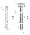
- FIG. 3 depicts a detailed side elevational view of the illuminating guide wire of FIG. 2A ;
- FIG. 4 depicts a detailed side cross-sectional view of the illuminating guidewire of FIG. 2A ;
- FIG. 5 depicts a perspective view of an exemplary endoscope suitable for use with the dilation catheter system of FIG. 1 ;
- FIG. 6 depicts a side elevational view of the distal end of the endoscope of FIG. 5 , showing an exemplary range of viewing angles;
- FIG. 7A depicts a front view of the guide catheter of FIG. 2B positioned adjacent an ostium of the maxillary sinus;
- FIG. 7B depicts a front view of the guide catheter of FIG. 2B positioned adjacent an ostium of the maxillary sinus, with the dilation catheter of FIG. 2C and the illuminating guidewire of FIG. 2A positioned in the guide catheter and a distal portion of the guidewire positioned in the maxillary sinus;
- FIG. 7C depicts a front view of the guide catheter of FIG. 2B positioned adjacent an ostium of the maxillary sinus, with the illuminating guidewire of FIG. 2A translated further distally relative to the guide catheter and into the maxillary sinus;
- FIG. 7D depicts a front view of the guide catheter of FIG. 2B positioned adjacent an ostium of the maxillary sinus, with the dilation catheter of FIG. 2C translated distally relative to the guide catheter along the illuminating guidewire of FIG. 2A so as to position a balloon of the dilation catheter within the ostium;
- FIG. 7E depicts a front view of an ostium of the maxillary sinus, with the ostium having been enlarged by inflation of the balloon of FIG. 7D ;
- FIG. 8 depicts a perspective view of an exemplary alternative illuminating guidewire suitable for use with the dilation catheter system of FIG. 1 ;
- FIG. 9 depicts cross-sectional side view of the distal end of the illuminating guidewire of FIG. 8 ;
- FIG. 10A depicts a front view of the guide catheter of FIG. 2B positioned adjacent an ostium of the maxillary sinus, with the dilation catheter of FIG. 2C and the illuminating guidewire of FIG. 8 positioned therein, and with the illuminating guidewire projecting light through the ostium of the maxillary sinus;
- FIG. 10B depicts a front view of the guide catheter of FIG. 2B positioned adjacent an ostium of the maxillary sinus, with the illuminating guidewire of FIG. 8 translated distally relative to the guide catheter, and with the illuminating guidewire projecting light into a superior lateral region of the maxillary sinus;
- FIG. 10C depicts a front view of the guide catheter of FIG. 2B positioned adjacent an ostium of the maxillary sinus, with the illuminating guidewire of FIG. 8 translated further distally relative to the guide catheter and into the maxillary sinus, with the illuminating guide wire rotated to a first rotational position, and with the illuminating guidewire projecting light into an inferior medial region of the maxillary sinus;
- FIG. 10D depicts a front view of the guide catheter of FIG. 2B positioned adjacent an ostium of the maxillary sinus, with the illuminating guide wire of FIG. 8 rotated to a second rotational position, and with the illuminating guidewire projecting light into a superior lateral region of the maxillary sinus;
- FIG. 10E depicts a front view of the guide catheter of FIG. 2B positioned adjacent an ostium of the maxillary sinus, with the illuminating guide wire of FIG. 8 rotated to a third rotational position, and with the illuminating guidewire projecting light into an inferior region of the maxillary sinus;
- FIG. 10F depicts a front view of the guide catheter of FIG. 2B positioned adjacent an ostium of the maxillary sinus, with the illuminating guidewire of FIG. 8 translated further distally relative to the guide catheter into the maxillary sinus, and with the illuminating guidewire projecting light into an inferior region of the maxillary sinus;
- FIG. 11 depicts an exemplary detailed cross-sectional side view of the distal end of an exemplary alternative illuminating guidewire suitable for use with the dilation catheter system of FIG. 1 ;
- FIG. 12A depicts a front view of the guide catheter of FIG. 2B positioned adjacent an ostium of the maxillary sinus, with the dilation catheter of FIG. 2C and the illuminating guidewire of FIG. 11 positioned therein, and with the illuminating guidewire projecting light through the ostium of the maxillary sinus;
- FIG. 12B depicts a front view of the guide catheter of FIG. 2B positioned adjacent an ostium of the maxillary sinus, with the illuminating guidewire of FIG. 11 translated distally relative to the guide catheter, and with the illuminating guidewire projecting light into a superior lateral region of the maxillary sinus;
- FIG. 12C depicts a front view of the guide catheter of FIG. 2B positioned adjacent an ostium of the maxillary sinus, with the illuminating guidewire of FIG. 11 translated further distally relative to the guide catheter and into the maxillary sinus, with the illuminating guide wire rotated to a first rotational position, and with the illuminating guidewire projecting light into an inferior medial region of the maxillary sinus;
- FIG. 12D depicts a front view of the guide catheter of FIG. 2B positioned adjacent an ostium of the maxillary sinus, with the illuminating guide wire of FIG. 11 rotated to a second rotational position, and with the illuminating guidewire projecting light into a superior lateral region of the maxillary sinus;
- FIG. 12E depicts a front view of the guide catheter of FIG. 2B positioned adjacent an ostium of the maxillary sinus, with the illuminating guide wire of FIG. 11 rotated to a third rotational position, and with the illuminating guidewire projecting light into an inferior region of the maxillary sinus;
- FIG. 12F depicts a front view of the guide catheter of FIG. 2B positioned adjacent an ostium of the maxillary sinus, with the illuminating guidewire of FIG. 11 translated further distally relative to the guide catheter into the maxillary sinus, and with the illuminating guidewire projecting light into an inferior region of the maxillary sinus.
- proximal and distal are used herein with reference to a clinician gripping a handpiece assembly.
- an end effector is distal with respect to the more proximal handpiece assembly.
- spatial terms such as “top” and “bottom” also are used herein with respect to the clinician gripping the handpiece assembly.
- surgical instruments are used in many orientations and positions, and these terms are not intended to be limiting and absolute.
- FIG. 1 shows an exemplary dilation catheter system ( 10 ) that may be used to dilate the ostium of a paranasal sinus; or to dilate some other anatomical passageway (e.g., within the ear, nose, or throat, etc.).
- Dilation catheter system ( 10 ) of this example comprises a dilation catheter ( 20 ), a guide catheter ( 30 ), an inflator ( 40 ), and a guidewire ( 50 ).
- dilation catheter system ( 10 ) may be configured in accordance with at least some of the teachings of U.S. Patent Pub. No. 2011/0004057, the disclosure of which is incorporated by reference herein.
- at least part of dilation catheter system ( 10 ) is configured similar to the Relieva® Spin Balloon SinuplastyTM System by Acclarent, Inc. of Menlo Park, Calif.
- the distal end (DE) of dilation catheter ( 20 ) includes an inflatable dilator ( 22 ).
- the proximal end (PE) of dilation catheter ( 20 ) includes a grip ( 24 ), which has a lateral port ( 26 ) and an open proximal end ( 28 ).
- a hollow-elongate shaft ( 18 ) extends distally from grip.
- Dilation catheter ( 20 ) includes a first lumen (not shown) formed within shaft ( 18 ) that provides fluid communication between lateral port ( 26 ) and the interior of dilator ( 22 ).
- Dilator catheter ( 20 ) also includes a second lumen (not shown) formed within shaft ( 18 ) that extends from open proximal end ( 28 ) to an open distal end that is distal to dilator ( 22 ). This second lumen is configured to slidably receive guidewire ( 50 ).
- the first and second lumens of dilator catheter ( 20 ) are fluidly isolated from each other.
- dilator ( 22 ) may be selectively inflated and deflated by communicating fluid along the first lumen via lateral port ( 26 ) while guidewire ( 50 ) is positioned within the second lumen.
- dilator catheter ( 20 ) is configured similar to the Relieva UltirraTM Sinus Balloon Catheter by Acclarent, Inc. of Menlo Park, Calif. In some other versions, dilator catheter ( 20 ) is configured similar to the Relieva Solo ProTM Sinus Balloon Catheter by Acclarent, Inc. of Menlo Park, Calif. Other suitable forms that dilator catheter ( 20 ) may take will be apparent to those of ordinary skill in the art in view of the teachings herein.
- guide catheter ( 30 ) of the present example includes a bent distal portion ( 32 ) at its distal end (DE) and a grip ( 34 ) at its proximal end (PE). Grip ( 34 ) has an open proximal end ( 36 ).
- Guide catheter ( 30 ) defines a lumen that is configured to slidably receive dilation catheter ( 20 ), such that guide catheter ( 30 ) may guide dilator ( 22 ) out through bent distal end ( 32 ).
- guide catheter ( 30 ) is configured similar to the Relieva FlexTM Sinus Guide Catheter by Acclarent, Inc. of Menlo Park, Calif. Other suitable forms that guide catheter ( 30 ) may take will be apparent to those of ordinary skill in the art in view of the teachings herein.
- inflator ( 40 ) of the present example comprises a barrel ( 42 ) that is configured to hold fluid and a plunger ( 44 ) that is configured to reciprocate relative to barrel ( 42 ) to selectively discharge fluid from (or draw fluid into) barrel ( 42 ).
- Barrel ( 42 ) is fluidly coupled with lateral port ( 26 ) via a flexible tube ( 46 ).
- inflator ( 40 ) is operable to add fluid to dilator ( 22 ) or withdraw fluid from dilator ( 22 ) by translating plunger ( 44 ) relative to barrel ( 42 ).
- the fluid communicated by inflator ( 40 ) comprises saline, though it should be understood that any other suitable fluid may be used.
- inflator ( 40 ) may be filled with fluid (e.g., saline, etc.).
- fluid e.g., saline, etc.
- the distal end of flexible tube ( 46 ) may be placed in a reservoir containing the fluid.
- Plunger ( 44 ) may then be retracted from a distal position to a proximal position to draw the fluid into barrel ( 42 ).
- Inflator ( 40 ) may then be held in an upright position, with the distal end of barrel ( 42 ) pointing upwardly, and plunger ( 44 ) may then be advanced to an intermediate or slightly distal position to purge any air from barrel ( 42 ).
- inflator ( 40 ) is constructed and operable in accordance with at least some of the teachings of U.S. Pub. No. 2014/0074141, entitled “Inflator for Dilation of Anatomical Passageway,” published Mar. 13, 2014, now U.S. Pat. No. 9,962,530, issued May 8, 2018, the disclosure of which is incorporated by reference herein.
- guidewire ( 50 ) of the present example comprises a coil ( 52 ) positioned about a core wire ( 54 ).
- An illumination fiber ( 56 ) extends along the interior of core wire ( 54 ) and terminates in an atraumatic lens ( 58 ).
- a connector ( 55 ) at the proximal end of guidewire ( 50 ) enables optical coupling between illumination fiber ( 56 ) and a light source (not shown).
- Illumination fiber ( 56 ) may comprise one or more optical fibers.
- Lens ( 58 ) is configured to project light when illumination fiber ( 56 ) is illuminated by the light source, such that illumination fiber ( 56 ) transmits light from the light source to the lens ( 58 ).
- the distal end of guidewire ( 50 ) is more flexible than the proximal end of guidewire ( 50 ).
- Guidewire ( 50 ) has a length enabling the distal end of guidewire ( 50 ) to be positioned distal to dilator ( 22 ) while the proximal end of guidewire ( 50 ) is positioned proximal to grip ( 24 ).
- Guidewire ( 50 ) may include indicia along at least part of its length (e.g., the proximal portion) to provide the operator with visual feedback indicating the depth of insertion of guidewire ( 50 ) relative to dilation catheter ( 20 ).
- guidewire ( 50 ) may be configured in accordance with at least some of the teachings of U.S. Pub.
- guidewire ( 50 ) is configured similar to the Relieva Luma SentryTM Sinus Illumination System by Acclarent, Inc. of Menlo Park, Calif. Other suitable forms that guidewire ( 50 ) may take will be apparent to those of ordinary skill in the art in view of the teachings herein.
- an endoscope ( 60 ) may be used to provide visualization within an anatomical passageway (e.g., within the nasal cavity, etc.) during a process of using dilation catheter system ( 10 ).
- endoscope of the present example comprises a body ( 62 ) and a rigid shaft ( 64 ) extending distally from body ( 62 ).
- the distal end of shaft ( 64 ) includes a curved transparent window ( 66 ).
- a plurality of rod lenses and light transmitting fibers may extend along the length of shaft ( 64 ).
- a lens is positioned at the distal end of the rod lenses and a swing prism is positioned between the lens and window ( 66 ).
- the swing prism is pivotable about an axis that is transverse to the longitudinal axis of shaft ( 64 ).
- the swing prism defines a line of sight that pivots with the swing prism.
- the line of sight defines a viewing angle relative to the longitudinal axis of shaft ( 64 ). This line of sight may pivot from approximately 0 degrees to approximately 120 degrees, from approximately 10 degrees to approximately 90 degrees, or within any other suitable range.
- the swing prism and window ( 66 ) also provide a field of view spanning approximately 60 degrees (with the line of sight centered in the field of view). Thus, the field of view enables a viewing range spanning approximately 180 degrees, approximately 140 degrees, or any other range, based on the pivot range of the swing prism. Of course, all of these values are mere examples.
- Body ( 62 ) of the present example includes a light post ( 70 ), an eyepiece ( 72 ), a rotation dial ( 74 ), and a pivot dial ( 76 ).
- Light post ( 70 ) is in communication with the light transmitting fibers in shaft ( 64 ) and is configured to couple with a source of light, to thereby illuminate the site in the patient distal to window ( 66 ).
- Eyepiece ( 72 ) is configured to provide visualization of the view captured through window ( 66 ) via the optics of endoscope ( 60 ).
- a visualization system e.g., camera and display screen, etc.
- Rotation dial ( 74 ) is configured to rotate shaft ( 64 ) relative to body ( 62 ) about the longitudinal axis of shaft ( 64 ). It should be understood that such rotation may be carried out even while the swing prism is pivoted such that the line of sight is non-parallel with the longitudinal axis of shaft ( 64 ).
- Pivot dial ( 76 ) is coupled with the swing prism and is thereby operable to pivot the swing prism about the transverse pivot axis.
- Indicia ( 78 ) on body ( 62 ) provide visual feedback indicating the viewing angle.
- Various suitable components and arrangements that may be used to couple rotation dial ( 74 ) with the swing prism will be apparent to those of ordinary skill in the art in view of the teachings herein.
- endoscope ( 60 ) may be configured in accordance with at least some of the teachings of U.S. Pub. No. 2010/0030031, the disclosure of which is incorporated by reference herein.
- endoscope ( 60 ) is configured similar to the Acclarent CyclopsTM Multi-Angle Endoscope by Acclarent, Inc. of Menlo Park, Calif.
- Other suitable forms that endoscope ( 60 ) may take will be apparent to those of ordinary skill in the art in view of the teachings herein
- FIGS. 7A-7E show an exemplary method for using dilation catheter system ( 10 ) discussed above to dilate a sinus ostium (O) of a maxillary sinus (MS) of a patient. While the present example is being provided in the context of dilating a sinus ostium (O) of a maxillary sinus (MS), it should be understood that dilation catheter system ( 10 ) may be used in various other procedures.
- dilation catheter system ( 10 ) and variations thereof may be used to dilate a Eustachian tube, a larynx, a choana, a sphenoid sinus ostium, one or more openings associated with one or more ethmoid sinus air cells, the frontal recess, and/or other passageways associated with paranasal sinuses.
- dilation catheter system ( 10 ) may be used to dilate a Eustachian tube, a larynx, a choana, a sphenoid sinus ostium, one or more openings associated with one or more ethmoid sinus air cells, the frontal recess, and/or other passageways associated with paranasal sinuses.
- Other suitable ways in which dilation catheter system ( 10 ) may be used will be apparent to those of ordinary skill in the art in view of the teachings herein.
- guide catheter ( 30 ) may be inserted transnasally and advanced through the nasal cavity (NC) to a position within or near the targeted anatomical passageway to be dilated, the sinus ostium (O), as shown in FIG. 7A .
- Inflatable dilator ( 22 ) and the distal end of guidewire ( 50 ) may be positioned within or proximal to bent distal end ( 32 ) of guide catheter ( 30 ) at this stage.
- This positioning of guide catheter ( 30 ) may be verified endoscopically with an endoscope such as endoscope ( 60 ) described above and/or by direct visualization, radiography, and/or by any other suitable method.
- the operator may advance guidewire ( 50 ) distally through guide catheter ( 30 ) such that a distal portion of the guidewire ( 50 ) passes through the ostium (O) of the maxillary sinus (MS) and into the cavity of the maxillary sinus (MS) as shown in FIGS. 7B and 7C .
- the operator may illuminate illumination fiber ( 56 ) and lens ( 58 ), which may provide transcutaneous illumination through the patient's face to enable the operator to visually confirm positioning of the distal end of guidewire ( 50 ) in the maxillary sinus (MS) with relative ease.
- dilation catheter ( 20 ) is advanced along guidewire ( 50 ) and through bent distal end ( 32 ) of guide catheter ( 30 ), with dilator ( 22 ) in a non-dilated state until dilator ( 22 ) is positioned within the ostium (O) of the maxillary sinus (MS) (or some other targeted anatomical passageway).
- dilator ( 22 ) may be inflated, thereby dilating the ostium (O), as shown in FIG. 7D .
- plunger ( 44 ) may be actuated to push saline from barrel ( 42 ) of inflator ( 40 ) through dilation catheter ( 20 ) into dilator ( 22 ).
- the transfer of fluid expands dilator ( 22 ) to an expanded state to open or dilate the ostium (O), such as by remodeling the bone, etc., forming ostium (O).
- dilator ( 22 ) may be inflated to a volume sized to achieve about 10 to about 12 atmospheres. Dilator ( 22 ) may be held at this volume for a few seconds to sufficiently open the ostium (O) (or other targeted anatomical passageway).
- Dilator ( 22 ) may then be returned to a non-expanded state by reversing plunger ( 44 ) of inflator ( 40 ) to bring the saline back to inflator ( 40 ).
- Dilator ( 22 ) may be repeatedly inflated and deflated in different ostia and/or other targeted anatomical passageways. Thereafter, dilation catheter ( 20 ), guidewire ( 50 ), and guide catheter ( 30 ) may be removed from the patient as shown in FIG. 7E .
- guide catheter ( 30 ) may be allowed to remain in place after removal of guidewire ( 50 ) and dilation catheter ( 20 ) and a lavage fluid, other substance, or one or more other devices (e.g., lavage catheters, balloon catheters, cutting balloons, cutters, chompers, rotating cutters, rotating drills, rotating blades, sequential dilators, tapered dilators, punches, dissectors, burs, non-inflating mechanically expandable members, high frequency mechanical vibrators, dilating stents and radiofrequency ablation devices, microwave ablation devices, laser devices, snares, biopsy tools, scopes, and devices that deliver diagnostic or therapeutic agents) may be passed through guide catheter ( 30 ) for further treatment of the condition.
- devices e.g., lavage catheters, balloon catheters, cutting balloons, cutters, chompers, rotating cutters, rotating drills, rotating blades, sequential dilators, tapered dilators, punches, dissectors, burs, non
- irrigation may be carried out in accordance with at least some of the teachings of U.S. Pat. Pub. No. 2008/0183128, entitled “Methods, Devices and Systems for Treatment and/or Diagnosis of Disorders of the Ear, Nose and Throat,” published on Jul. 31, 2008, the disclosure of which is incorporated by reference herein.
- An example of an irrigation catheter that may be fed through guide catheter ( 30 ) to reach the irrigation site after removal of dilation catheter ( 20 ) is the Relieva Vortex®. Sinus Irrigation Catheter by Acclarent, Inc. of Menlo Park, Calif.
- irrigation catheter that may be fed through guide catheter ( 30 ) to reach the irrigation site after removal of dilation catheter ( 20 ) is the Relieva Ultirra®. Sinus Irrigation Catheter by Acclarent, Inc. of Menlo Park, Calif. Of course, irrigation may be provided in the absence of a dilation procedure; and a dilation procedure may be completed without also including irrigation.
- dilation catheter system ( 10 ) it may be desirable to provide illuminating guidewire ( 50 ) with features that allow an operator to receive information concerning a position of guidewire ( 50 ) within the patient even when guidewire ( 50 ) is not visible via endoscope ( 60 ); and when guidewire ( 50 ) is not yet in a position to provide transillumination that is visible from outside the patient.
- guidewire ( 50 ) may be provided with light transmitting features that are configured to transmit light distally (i.e., from the proximal end (PE) of guidewire ( 50 ) to the distal end (DE) of guidewire ( 50 )) and proximally (i.e., from the distal end (DE) of guidewire ( 50 ) to the proximal end (PE) of guidewire ( 50 )) along the length of guidewire ( 50 ).
- such bi-directional transmission of light may be used to indicate and/or detect a position of guidewire ( 50 ) within a patient.
- FIG. 8 shows an exemplary flexible-illuminating guidewire ( 200 ) that may be readily incorporated into dilation catheter system ( 10 ) in place of guidewire ( 50 ).
- Guidewire ( 200 ) of the present example includes a preformed bent distal portion ( 202 ) at its distal end (DE).
- bent distal portion (DE) defines an obtuse angle.
- bent distal portion has a curved configuration rather than an angular configuration.
- distal portion (DE) is simply straight, such that there is no curve or angular bend.
- bent distal portion ( 202 ) is operable transmit light over a selected region as the result of rotating guidewire ( 200 ) about the longitudinal axis of guidewire ( 200 ).
- guidewire ( 200 ) of the present example comprises a coil ( 204 ) positioned about a core wire ( 206 ).
- An illumination fiber ( 208 ) extends along the interior of core wire ( 206 ), alongside core wire ( 206 ), and terminates in an atraumatic lens ( 210 ).
- illumination fiber ( 208 ) of the present example comprises a single optical fiber
- illumination fiber ( 208 ) may be supplemented with additional optical fibers as will be described in more detail below.
- Lens ( 210 ) is configured to project light when illumination fiber ( 208 ) is illuminated by a light source, such that illumination fiber ( 208 ) transmits light from the light source to the lens ( 210 ).
- lens ( 210 ) is further configured to receive and transmit light to illumination fiber ( 208 ) when that light is reflected from beyond the distal end (DE) of guidewire ( 200 ).
- the distal end (DE) of guidewire ( 200 ) is more flexible than the proximal end (PE) of guidewire ( 200 ).
- Guidewire ( 200 ) has a length enabling the distal end (DE) of guidewire ( 200 ) to be positioned distal to dilator ( 22 ) while the proximal end (PE) of guidewire ( 200 ) is positioned proximal to grip ( 24 ).
- Guidewire ( 200 ) may include indicia along at least part of its length (e.g., the proximal portion) to provide the operator with visual feedback indicating the depth of insertion of guidewire ( 200 ) relative to dilation catheter ( 20 ).
- guidewire ( 200 ) may be configured and operable in accordance with at least some of the teachings of U.S. Pub. No. 2012/0078118, now U.S. Pat. No. 9,155,492, issued Oct. 13, 2015, the disclosure of which is incorporated by reference herein.
- guidewire ( 200 ) is configured similar to the Relieva Luma SentryTM Sinus Illumination System by Acclarent, Inc. of Menlo Park, Calif.
- Other suitable forms that guidewire ( 200 ) may take will be apparent to those of ordinary skill in the art in view of the teachings herein.
- FIGS. 10A-10F show an exemplary illuminating system ( 300 ) and an exemplary method for using illuminating system ( 300 ) with guidewire ( 200 ) to access the maxillary sinus (MS) of a patient.
- Illuminating system ( 300 ) of the present example comprises a conventional light source ( 302 ), a conventional beam splitter ( 304 ), and a conventional light detector ( 306 ).
- Light source ( 302 ) may comprise any suitable kind of light source ( 302 ) and may include various components, including but not limited to a laser, a beam collimator, focusing optics, etc.
- Light source ( 302 ) may be operable to communicate any suitable kind of light, including but not limited to white/visible light, near-infrared light, infrared light, etc.
- Beam splitter ( 304 ) is operable to reflect light from light source ( 302 ) in a first direction along a reflected light axis; and transmit light in a second direction along the same axis.
- Light detector ( 306 ) is configured to receive light that is transmitted through beam splitter ( 304 ) in the second direction along the reflected light axis.
- Light detector ( 306 ) includes a sensor that is operable to generate electrical signals based on light received by the sensor.
- Light detector ( 306 ) may further include hardware that is configured to process those generated electrical signals and generate some kind of output that provides feedback to the operator relating to the light received by light detector ( 306 ).
- Such feedback may include audible feedback (e.g., an audible tone, a voice providing spoken words, etc.), visual feedback (e.g., a selectively illuminating LED, a graphical interface providing graphic and/or textual feedback, etc.), and/or tactile feedback (e.g., a feature providing a vibration through a handpiece associated with guide catheter ( 30 ), etc.).
- detector ( 306 ) may be desirable to configure detector ( 306 ) such that detector ( 306 ) is operable to “subtract” any unwanted light from light scattering, reflection, or other optical phenomena so as to improve upon the information indicated by detector ( 306 ).
- detector ( 306 ) may be desirable to configure detector ( 306 ) such that detector ( 306 ) is operable to “subtract” any unwanted light from light scattering, reflection, or other optical phenomena so as to improve upon the information indicated by detector ( 306 ).
- detector ( 306 ) it may be desirable to configure detector ( 306 ) such that detector ( 306 ) is operable to “subtract” any unwanted light from light scattering, reflection, or other optical phenomena so as to improve upon the information indicated by detector ( 306 ).
- suitable ways in which such subtraction may be provided will be apparent to those of ordinary skill in the art in view of the teachings herein.
- guide catheter ( 30 ) may be inserted transnasally and advanced through the nasal cavity (NC) to a position within or near the ostium (O) of the maxillary sinus (MO) as shown in FIG. 10A .
- the distal end (DE) of guidewire ( 200 ) may be positioned adjacent the distal end (DE) of guide catheter ( 30 ).
- light source ( 302 ) projects light toward beam splitter ( 304 ).
- Beam splitter ( 304 ) redirects a portion of the light to project distally through illumination fiber ( 208 ) of guidewire ( 200 ).
- This light is transmitted through illumination fiber ( 208 ) and is emitted from the distal end (DE) of guidewire ( 200 ) via lens ( 210 ).
- This emitted light can serve as a source of transilluminating light operable to indicate a position of the distal end (DE) of guidewire ( 200 ) by visualization through the anatomical structure(s) that surrounds the distal end (DE) of guidewire ( 200 ).
- the anatomical structure(s) that surrounds the distal end (DE) of guidewire ( 200 ) may reflect at least a portion of this emitted light back toward the distal end (DE) of guidewire ( 200 ). This reflected light enters illumination fiber ( 208 ) via lens ( 210 ).
- the reflected light is then transmitted proximally through illumination fiber ( 208 ) and is emitted from the proximal end (PE) of guidewire ( 200 ).
- This light emitted from the proximal end (PE) of guidewire ( 200 ) is then transmitted through beam splitter ( 304 ) toward detector ( 306 ).
- Detector ( 306 ) is then operable to determine and/or indicate the presence and characteristics of reflected light to thereby determine and/or indicate the presence of anatomical structure(s) that are distal to distal end (DE) of guidewire ( 200 ).
- detector ( 306 ) and/or components that are coupled with detector ( 306 ) may further provide real-time feedback to the operator concerning the position of guidewire ( 200 ) and/or the anatomical structure(s) that are distal to distal end (DE) of guidewire ( 200 ).
- detector ( 306 ) may be operable to indicate a distance between the distal end (DE) of guidewire ( 200 ) and the anatomical structure(s) that surrounds the distal end (DE) of guidewire ( 200 ) as well as the color of such anatomical structure(s).
- detector ( 306 ) may indicate a distance between the distal end (DE) of guidewire ( 200 ) and the anatomical structure(s) that surround the distal end (DE) of guidewire ( 200 ) as wells as the type and/or pathology of anatomical structure(s) that surrounds the distal end (DE) of guidewire ( 200 ). For instance, as shown in FIG.
- detector ( 306 ) and/or components that are coupled with detector ( 306 ) may be configured to provide visual, audible, and/or tactile feedback to an operator based on such information.
- the operator may advance guidewire ( 200 ) distally through guide catheter ( 30 ) such that a distal portion of the guidewire ( 200 ) passes through the ostium (O) of the maxillary sinus (MS) and into the cavity of the maxillary sinus (MS).
- guidewire ( 200 ) is constantly projecting light from its distal end (DE) so as to provide continuous feedback to the operator.
- bent distal portion ( 202 ) causes light from the distal end (DE) of guidewire ( 200 ) to be projected over a substantial portion of the maxillary sinus (MS).
- the operator is able to receive feedback concerning the internal shape of the maxillary sinus (MS) such that the operator can determine along which path to translate guidewire ( 200 ) as shown in FIG. 10F .
- detector ( 306 ) is operable to determine and/or indicate the presence and characteristics of reflected light to thereby determine and/or indicate the presence of anatomical structure(s) that are distal to distal end (DE) of guidewire ( 200 ). Based on signals from detector ( 306 ), detector ( 306 ) and/or components that are coupled with detector ( 306 ) may further provide real-time feedback to the operator concerning the position of guidewire ( 200 ) and/or the anatomical structure(s) that are distal to distal end (DE) of guidewire ( 200 ).
- the system may further be configured to determine the character of tissue based on reflected light that is received by detector ( 306 ).
- detector ( 306 ) and/or components that are coupled with detector ( 306 ) may process characteristics of the reflected light such as wavelength, etc.; and may interpret tissue conditions based on such characteristics for the reflected light.
- the reflected light may indicate tissue conditions such as density, swelling, infection, and/or various other conditions.
- tissue conditions such as density, swelling, infection, and/or various other conditions.
- suitable tissue conditions that may be identified based on the characteristics of light reflected off of the tissue will be apparent to those of ordinary skill in the art in view of the teachings herein.
- various ways of processing reflected light to determine such tissue conditions will be apparent to those of ordinary skill in the art in view of the teachings herein.
- guidewire ( 200 ) may advance dilation catheter ( 20 ) along guidewire ( 200 ) to position dilator ( 22 ) in the ostium (O) of the maxillary sinus (MS).
- the operator may then inflate dilator ( 22 ) as described above to dilate the ostium (O).
- the operator may perform any other desired actions within the maxillary sinus (MS), within the ostium (O), and/or elsewhere. It should be understood that, while the present example is being provided in the context of a maxillary sinus (MS), guidewire ( 200 ) may be used in various other procedures.
- guidewire ( 200 ) and variations thereof may be used in or near a Eustachian tube, a larynx, a choana, a sphenoid sinus, one or more ethmoid sinus air cells, the frontal recess, the frontal sinus, other paranasal cavities, and/or other passageways associated with paranasal sinuses.
- Other suitable ways in which guidewire ( 200 ) may be used will be apparent to those of ordinary skill in the art in view of the teachings herein.
- FIG. 11 depicts another exemplary flexible-illuminating guidewire ( 400 ) that may be readily incorporated into dilation catheter system ( 10 ) in place of guidewire ( 50 ).
- Guidewire ( 400 ) of the present example comprises a coil ( 404 ) positioned about a core wire ( 406 ).
- a pair of illumination fibers ( 407 , 408 ) extends along the interior of core wire ( 406 ) and terminates in an atraumatic lens ( 410 ).
- Lens ( 410 ) is configured to project light when illumination fiber ( 407 ) is illuminated by a light source, such that illumination fiber ( 407 ) transmits light from the light source to the lens ( 410 ).
- lens ( 410 ) is further configured to receive and transmit light to illumination fiber ( 408 ) when that light is reflected from beyond the distal end (DE) of guidewire ( 400 ).
- guidewire ( 400 ) includes a bent distal portion ( 402 ) in accordance with the above discussion of guidewire ( 200 ). In some other versions, the distal portion of guidewire ( 400 ) is straight. It should also be understood that the distal end (DE) of guidewire ( 400 ) may be more flexible than the proximal end (PE) of guidewire ( 400 ). Guidewire ( 400 ) has a length enabling the distal end (DE) of guidewire ( 400 ) to be positioned distal to dilator ( 22 ) while the proximal end (PE) of guidewire ( 400 ) is positioned proximal to grip ( 24 ).
- Guidewire ( 400 ) may include indicia along at least part of its length (e.g., the proximal portion) to provide the operator with visual feedback indicating the depth of insertion of guidewire ( 400 ) relative to dilation catheter ( 20 ).
- guidewire ( 400 ) may be configured and operable in accordance with at least some of the teachings of U.S. Pub. No. 2012/0078118, now U.S. Pat. No. 9,155,492, issued Oct. 13, 2015, the disclosure of which is incorporated by reference herein.
- guidewire ( 400 ) is configured similar to the Relieva Luma SentryTM Sinus Illumination System by Acclarent, Inc. of Menlo Park, Calif.
- Other suitable forms that guidewire ( 400 ) may take will be apparent to those of ordinary skill in the art in view of the teachings herein.
- FIGS. 12A-12F show an exemplary illuminating system ( 500 ) and an exemplary method for using illuminating system ( 500 ) with guidewire ( 400 ) to access the maxillary sinus (MS) of a patient.
- Illuminating system ( 500 ) of the present example comprises a conventional light source ( 502 ) and a conventional light detector ( 506 ).
- Light source ( 502 ) is optically coupled with illumination fiber ( 407 ) while light detector ( 506 ) is optically coupled with illumination fiber ( 408 ).
- Light source ( 502 ) may comprise any suitable kind of light source ( 502 ) and may include various components, including but not limited to a laser, a beam collimator, focusing optics, etc.
- Light source ( 502 ) may be operable to communicate any suitable kind of light, including but not limited to white/visible light, near-infrared light, infrared light, etc.
- Light detector ( 506 ) is configured to receive light that is transmitted through illumination fiber ( 408 ).
- Light detector ( 506 ) includes a sensor that is operable to generate electrical signals based on light received by the sensor.
- Light detector ( 506 ) may further include hardware that is configured to process those generated electrical signals and generate some kind of output that provides feedback to the operator relating to the light received by light detector ( 506 ).
- Such feedback may include audible feedback (e.g., an audible tone, a voice providing spoken words, etc.), visual feedback (e.g., a selectively illuminating LED, a graphical interface providing graphic and/or textual feedback, etc.), and/or tactile feedback (e.g., a feature providing a vibration through a handpiece associated with guide catheter ( 30 ), etc.).
- detector ( 506 ) may be desirable to configure detector ( 506 ) such that detector ( 506 ) is operable to “subtract” any unwanted light from light scattering, reflection, or other optical phenomena so as to improve upon the information indicated by detector ( 506 ).
- detector ( 506 ) may be desirable to configure detector ( 506 ) such that detector ( 506 ) is operable to “subtract” any unwanted light from light scattering, reflection, or other optical phenomena so as to improve upon the information indicated by detector ( 506 ).
- detector ( 506 ) it may be desirable to configure detector ( 506 ) such that detector ( 506 ) is operable to “subtract” any unwanted light from light scattering, reflection, or other optical phenomena so as to improve upon the information indicated by detector ( 506 ).
- suitable ways in which such subtraction may be provided will be apparent to those of ordinary skill in the art in view of the teachings herein.
- guide catheter ( 30 ) may be inserted transnasally and advanced through the nasal cavity (NC) to a position within or near the ostium (O) of the maxillary sinus (MO) as shown in FIG. 12A .
- the distal end (DE) of guidewire ( 400 ) may be positioned adjacent the distal end (DE) of guide catheter ( 30 ).
- light source ( 502 ) projects light toward illumination fiber ( 407 ) of guidewire ( 400 ). This light is transmitted through illumination fiber ( 407 ) and is emitted from the distal end (DE) of guidewire ( 400 ) via lens ( 410 ).
- This emitted light can serve as a source of transilluminating light operable to indicate a position of the distal end (DE) of guidewire ( 400 ) by visualization through the anatomical structure(s) that surrounds the distal end (DE) of guidewire ( 400 ). Further, the anatomical structure(s) that surrounds the distal end (DE) of guidewire ( 400 ) may reflect at least a portion of this emitted light back toward the distal end (DE) of guidewire ( 400 ). This reflected light enters illumination fiber ( 408 ) via lens ( 410 ). The reflected light is then transmitted proximally through illumination fiber ( 408 ) and is emitted from the proximal end (PE) of guidewire ( 400 ) toward detector ( 506 ).
- Detector ( 506 ) is then operable to determine and/or indicate the presence and characteristics of reflected light to thereby determine and/or indicate the presence of anatomical structure(s) that are distal to distal end (DE) of guidewire ( 400 ).
- detector ( 506 ) and/or components that are coupled with detector ( 506 ) may further provide real-time feedback to the operator concerning the position of guidewire ( 400 ) and/or the anatomical structure(s) that are distal to distal end (DE) of guidewire ( 400 ).
- detector ( 506 ) may be operable to indicate a distance between the distal end (DE) of guidewire ( 400 ) and the anatomical structure(s) that surrounds the distal end (DE) of guidewire ( 400 ) as well as the color of such anatomical structure(s).
- detector ( 506 ) may indicate a distance between the distal end (DE) of guidewire ( 400 ) and the anatomical structure(s) that surround the distal end (DE) of guidewire ( 200 ) as wells as the type and/or pathology of anatomical structure(s) that surrounds the distal end (DE) of guidewire ( 400 ). For instance, as shown in FIG.
- detector ( 506 ) and/or components that are coupled with detector ( 506 ) may be configured to provide visual, audible, and/or tactile feedback to an operator based on such information.
- the operator may advance guidewire ( 400 ) distally through guide catheter ( 30 ) such that a distal portion of the guidewire ( 400 ) passes through the ostium (O) of the maxillary sinus (MS) and into the cavity of the maxillary sinus (MS).
- guidewire ( 400 ) is constantly projecting light from its distal end (DE) so as to provide continuous feedback to the operator.
- bent distal portion ( 402 ) causes light from the distal end (DE) of guidewire ( 400 ) to be projected over a substantial portion of the maxillary sinus (MS).
- the operator is able to receive feedback concerning the internal shape of the maxillary sinus (MS) such that the operator can determine along which path to translate guidewire ( 400 ) as shown in FIG. 12F .
- guidewire ( 400 ) may advance dilation catheter ( 20 ) along guidewire ( 400 ) to position dilator ( 22 ) in the ostium (O) of the maxillary sinus (MS).
- the operator may then inflate dilator ( 22 ) as described above to dilate the ostium (O).
- the operator may perform any other desired actions within the maxillary sinus (MS), within the ostium (O), and/or elsewhere. It should be understood that, while the present example is being provided in the context of a maxillary sinus (MS), guidewire ( 400 ) may be used in various other procedures.
- guidewire ( 400 ) and variations thereof may be used in or near a Eustachian tube, a larynx, a choana, a sphenoid sinus, one or more ethmoid sinus air cells, the frontal recess, the frontal sinus, other paranasal cavities, and/or other passageways associated with paranasal sinuses.
- Other suitable ways in which guidewire ( 400 ) may be used will be apparent to those of ordinary skill in the art in view of the teachings herein.
- a guide system comprising: (a) a guide member, wherein the guide member comprises a proximal end and a distal end, wherein the guide member comprises at least one illumination fiber; (b) a light source, wherein the light source is operable to project light to the proximal end of the guide member, wherein the at least one illumination fiber is operable to distally transmit the light projected by the light source from the proximal end of the guide member to the distal end of the guide member, wherein the distal end of the guide member is operable to project the distally transmitted light, wherein the distal end of the guide member is further operable to receive light projected from the distal end of the guide member and reflected back toward the distal end of the guide member, wherein the at least one illumination fiber is operable to proximally transmit the reflected light from the distal end of the guide member to the proximal end of the guide member; and (c) a detector, wherein the proximal end of the guide member is operable to project the prox
- Example 1 The guide system of Example 1, wherein the distal end of the guide member comprises an atraumatic lens.
- Example 4 The guide system of Example 4, wherein the beam splitter is operable to redirect the light projected by the light source toward the proximal end of the guide member.
- the at least one illumination fiber consists of a single illumination fiber, wherein the single illumination fiber is operable to both: (i) distally transmit the light projected by the light source from the proximal end of the guide member to the distal end of the guide member, and (ii) proximally transmit the reflected light from the distal end of the guide member to the proximal end of the guide member.
- the guide system any one or more of Examples 1 through 6 and 8, wherein the at least one illumination fiber comprises a first illumination fiber and a second illumination fiber, wherein the first illumination fiber is operable to distally transmit the light projected by the light source from the proximal end of the guide member to the distal end of the guide member.
- Example 9 The guide system of Example 9, wherein the second illumination fiber is operable to proximally transmit the reflected light from the distal end of the guide member to the proximal end of the guide member.
- Example 11 wherein the detector is further operable to determine the distance between the anatomical structure and the distal end of the guide member based upon the reflected light.
- a guide member positioning system comprising: (a) a guide member, wherein the guide member comprises a proximal end and a distal end, wherein the guide member comprises at least one illumination fiber, wherein the at least one illumination fiber is operable to transmit light from the proximal end to the distal end; (b) a light source, wherein the light source is operable to project light to the proximal end of the guide member; (c) a beam splitter, wherein the beam splitter is operable to redirect the light projected by the light source toward the proximal end of the guide member, wherein the at least one illumination fiber is operable to distally transmit the light redirected by the beam splitter from the proximal end of the guide member to the distal end of the guide member, wherein the distal end of the guide member is operable to project the distally transmitted light, wherein the distal end of the guide member is further operable to receive light projected from the distal end of the guide member and reflected back toward the distal end of the guide member
- a guide member positioning system comprising: (a) a guide member, wherein the guide member comprises a proximal end and a distal end, wherein the guide member comprises a first illumination fiber and a second illumination fiber; (b) a light source, wherein the light source is operable to project light to the first illumination fiber, wherein the first illumination fiber is operable to distally transmit the light projected by the light source from the proximal end of the guide member to the distal end of the guide member, wherein the distal end of the guide member is further operable to receive light projected from the distal end of the guide member and reflected back toward the distal end of the guide member, wherein the second illumination fiber is operable to proximally transmit the reflected light from the distal end of the guide member to the proximal end of the guide member; and (c) a detector, wherein the proximal end of the guide member is operable to project the proximally transmitted light toward the detector, wherein the detector is operable to detect the proximally transmitted light
- light and “light source” are used herein, it is contemplated that these terms include more than just visible light and sources of visible light. By way of example only, it is contemplated that the present teachings may be applied using infrared light, ultraviolet light, and other light that is not necessarily visible to the naked human eye. Therefore, the term “light” should be read to include non-visible light in addition to including non-visible light. Likewise, the term “light source’ should be read to include sources of visible light in addition to sources of non-visible light.
- any of the examples described herein may include various other features in addition to or in lieu of those described above.
- any of the examples described herein may also include one or more of the various features disclosed in any of the various references that are incorporated by reference herein.
- Versions of the devices disclosed herein can be designed to be disposed of after a single use, or they can be designed to be used multiple times. Versions may, in either or both cases, be reconditioned for reuse after at least one use. Reconditioning may include any combination of the steps of disassembly of the device, followed by cleaning or replacement of particular pieces, and subsequent reassembly. In particular, versions of the device may be disassembled, and any number of the particular pieces or parts of the device may be selectively replaced or removed in any combination. Upon cleaning and/or replacement of particular parts, versions of the device may be reassembled for subsequent use either at a reconditioning facility, or by a surgical team immediately prior to a surgical procedure.
- reconditioning of a device may utilize a variety of techniques for disassembly, cleaning/replacement, and reassembly. Use of such techniques, and the resulting reconditioned device, are all within the scope of the present application.
- versions described herein may be processed before surgery.
- a new or used instrument may be obtained and if necessary cleaned.
- the instrument may then be sterilized.
- the instrument is placed in a closed and sealed container, such as a plastic or TYVEK bag.
- the container and instrument may then be placed in a field of radiation that can penetrate the container, such as gamma radiation, x-rays, or high-energy electrons.
- the radiation may kill bacteria on the instrument and in the container.
- the sterilized instrument may then be stored in the sterile container.
- the sealed container may keep the instrument sterile until it is opened in a surgical facility.
- a device may also be sterilized using any other technique known in the art, including but not limited to beta or gamma radiation, ethylene oxide, or steam.
Landscapes
- Health & Medical Sciences (AREA)
- Life Sciences & Earth Sciences (AREA)
- Engineering & Computer Science (AREA)
- Surgery (AREA)
- Heart & Thoracic Surgery (AREA)
- Veterinary Medicine (AREA)
- Public Health (AREA)
- Biomedical Technology (AREA)
- General Health & Medical Sciences (AREA)
- Animal Behavior & Ethology (AREA)
- Biophysics (AREA)
- Molecular Biology (AREA)
- Medical Informatics (AREA)
- Pathology (AREA)
- Physics & Mathematics (AREA)
- Nuclear Medicine, Radiotherapy & Molecular Imaging (AREA)
- Optics & Photonics (AREA)
- Radiology & Medical Imaging (AREA)
- Anesthesiology (AREA)
- Hematology (AREA)
- Pulmonology (AREA)
- Otolaryngology (AREA)
- Human Computer Interaction (AREA)
- Oral & Maxillofacial Surgery (AREA)
- Dentistry (AREA)
- Biodiversity & Conservation Biology (AREA)
- Vascular Medicine (AREA)
- Child & Adolescent Psychology (AREA)
- Surgical Instruments (AREA)
- Endoscopes (AREA)
- Media Introduction/Drainage Providing Device (AREA)
- Laser Surgery Devices (AREA)
Priority Applications (7)
| Application Number | Priority Date | Filing Date | Title |
|---|---|---|---|
| US14/824,377 US10064555B2 (en) | 2015-03-31 | 2015-08-12 | Illuminating guidewire with optical sensing |
| MA042010A MA42010A (fr) | 2015-03-31 | 2016-03-29 | Fil-guide d'éclairage muni de détection optique |
| JP2017551079A JP2018515168A (ja) | 2015-03-31 | 2016-03-29 | 光センシングを備える照明ガイドワイヤ |
| EP16715959.9A EP3277150A1 (fr) | 2015-03-31 | 2016-03-29 | Fil-guide d'éclairage muni de détection optique |
| PCT/US2016/024719 WO2016160807A1 (fr) | 2015-03-31 | 2016-03-29 | Fil-guide d'éclairage muni de détection optique |
| CN201680031913.7A CN107666852B (zh) | 2015-03-31 | 2016-03-29 | 具有光学感测的照明导丝 |
| KR1020177031007A KR20170133412A (ko) | 2015-03-31 | 2016-03-29 | 광학 감지부를 가진 조명 가이드와이어 |
Applications Claiming Priority (2)
| Application Number | Priority Date | Filing Date | Title |
|---|---|---|---|
| US201562140643P | 2015-03-31 | 2015-03-31 | |
| US14/824,377 US10064555B2 (en) | 2015-03-31 | 2015-08-12 | Illuminating guidewire with optical sensing |
Publications (2)
| Publication Number | Publication Date |
|---|---|
| US20160287083A1 US20160287083A1 (en) | 2016-10-06 |
| US10064555B2 true US10064555B2 (en) | 2018-09-04 |
Family
ID=55745831
Family Applications (1)
| Application Number | Title | Priority Date | Filing Date |
|---|---|---|---|
| US14/824,377 Active 2036-01-19 US10064555B2 (en) | 2015-03-31 | 2015-08-12 | Illuminating guidewire with optical sensing |
Country Status (7)
| Country | Link |
|---|---|
| US (1) | US10064555B2 (fr) |
| EP (1) | EP3277150A1 (fr) |
| JP (1) | JP2018515168A (fr) |
| KR (1) | KR20170133412A (fr) |
| CN (1) | CN107666852B (fr) |
| MA (1) | MA42010A (fr) |
| WO (1) | WO2016160807A1 (fr) |
Cited By (2)
| Publication number | Priority date | Publication date | Assignee | Title |
|---|---|---|---|---|
| CN111973865A (zh) * | 2020-08-31 | 2020-11-24 | 尚华 | 一种光纤导丝、光纤导丝探测系统及方法 |
| US11376401B2 (en) | 2017-04-26 | 2022-07-05 | Acclarent, Inc. | Deflectable guide for medical instrument |
Families Citing this family (3)
| Publication number | Priority date | Publication date | Assignee | Title |
|---|---|---|---|---|
| US20190159666A1 (en) | 2017-11-27 | 2019-05-30 | Acclarent, Inc. | Surgical illumination system |
| US20190175887A1 (en) | 2017-12-13 | 2019-06-13 | Acclarent, Inc. | Dilation instrument with proximally located force sensor |
| US12144649B2 (en) * | 2018-08-14 | 2024-11-19 | Biosense Webster (Israel) Ltd. | Guidewire with an integrated optical fiber |
Citations (11)
| Publication number | Priority date | Publication date | Assignee | Title |
|---|---|---|---|---|
| US5383467A (en) * | 1992-11-18 | 1995-01-24 | Spectrascience, Inc. | Guidewire catheter and apparatus for diagnostic imaging |
| US5951482A (en) * | 1997-10-03 | 1999-09-14 | Intraluminal Therapeutics, Inc. | Assemblies and methods for advancing a guide wire through body tissue |
| EP1071370A1 (fr) | 1998-04-15 | 2001-01-31 | Intraluminal Therapeutics Inc. | Ensemble guide souple |
| US20080183128A1 (en) | 2007-01-24 | 2008-07-31 | John Morriss | Methods, devices and systems for treatment and/or diagnosis of disorders of the ear, nose and throat |
| US7630676B2 (en) | 2006-12-06 | 2009-12-08 | Xerox Corporation | Self-loading belt fusing apparatus |
| US20100030031A1 (en) | 2008-07-30 | 2010-02-04 | Acclarent, Inc. | Swing prism endoscope |
| US20110004057A1 (en) | 2004-04-21 | 2011-01-06 | Acclarent, Inc. | Systems and methods for transnasal dilation of passageways in the ear, nose or throat |
| EP2441489A2 (fr) | 2007-01-16 | 2012-04-18 | Entellus Medical, Inc. | Appareil de traitement de la sinusite |
| US20140074141A1 (en) | 2012-09-10 | 2014-03-13 | Acclarent, Inc. | Inflator for dilation of anatomical passageway |
| US20140275775A1 (en) | 2013-03-14 | 2014-09-18 | Acclarent, Inc. | Narrowband Illumination of Paranasal Cavities for Visual Localization of Target Tissue |
| US9155492B2 (en) | 2010-09-24 | 2015-10-13 | Acclarent, Inc. | Sinus illumination lightwire device |
Family Cites Families (1)
| Publication number | Priority date | Publication date | Assignee | Title |
|---|---|---|---|---|
| US5439000A (en) * | 1992-11-18 | 1995-08-08 | Spectrascience, Inc. | Method of diagnosing tissue with guidewire |
-
2015
- 2015-08-12 US US14/824,377 patent/US10064555B2/en active Active
-
2016
- 2016-03-29 MA MA042010A patent/MA42010A/fr unknown
- 2016-03-29 EP EP16715959.9A patent/EP3277150A1/fr not_active Withdrawn
- 2016-03-29 WO PCT/US2016/024719 patent/WO2016160807A1/fr not_active Ceased
- 2016-03-29 CN CN201680031913.7A patent/CN107666852B/zh not_active Expired - Fee Related
- 2016-03-29 KR KR1020177031007A patent/KR20170133412A/ko not_active Withdrawn
- 2016-03-29 JP JP2017551079A patent/JP2018515168A/ja not_active Abandoned
Patent Citations (11)
| Publication number | Priority date | Publication date | Assignee | Title |
|---|---|---|---|---|
| US5383467A (en) * | 1992-11-18 | 1995-01-24 | Spectrascience, Inc. | Guidewire catheter and apparatus for diagnostic imaging |
| US5951482A (en) * | 1997-10-03 | 1999-09-14 | Intraluminal Therapeutics, Inc. | Assemblies and methods for advancing a guide wire through body tissue |
| EP1071370A1 (fr) | 1998-04-15 | 2001-01-31 | Intraluminal Therapeutics Inc. | Ensemble guide souple |
| US20110004057A1 (en) | 2004-04-21 | 2011-01-06 | Acclarent, Inc. | Systems and methods for transnasal dilation of passageways in the ear, nose or throat |
| US7630676B2 (en) | 2006-12-06 | 2009-12-08 | Xerox Corporation | Self-loading belt fusing apparatus |
| EP2441489A2 (fr) | 2007-01-16 | 2012-04-18 | Entellus Medical, Inc. | Appareil de traitement de la sinusite |
| US20080183128A1 (en) | 2007-01-24 | 2008-07-31 | John Morriss | Methods, devices and systems for treatment and/or diagnosis of disorders of the ear, nose and throat |
| US20100030031A1 (en) | 2008-07-30 | 2010-02-04 | Acclarent, Inc. | Swing prism endoscope |
| US9155492B2 (en) | 2010-09-24 | 2015-10-13 | Acclarent, Inc. | Sinus illumination lightwire device |
| US20140074141A1 (en) | 2012-09-10 | 2014-03-13 | Acclarent, Inc. | Inflator for dilation of anatomical passageway |
| US20140275775A1 (en) | 2013-03-14 | 2014-09-18 | Acclarent, Inc. | Narrowband Illumination of Paranasal Cavities for Visual Localization of Target Tissue |
Non-Patent Citations (2)
| Title |
|---|
| International Search Report and Written Opinion dated Jun. 10, 2016 re Application No. PCT/US2016/024719. |
| U.S. Appl. No. 62/140,643, filed Mar. 31, 2015. |
Cited By (3)
| Publication number | Priority date | Publication date | Assignee | Title |
|---|---|---|---|---|
| US11376401B2 (en) | 2017-04-26 | 2022-07-05 | Acclarent, Inc. | Deflectable guide for medical instrument |
| US12357791B2 (en) | 2017-04-26 | 2025-07-15 | Acclarent, Inc. | Deflectable guide for medical instrument |
| CN111973865A (zh) * | 2020-08-31 | 2020-11-24 | 尚华 | 一种光纤导丝、光纤导丝探测系统及方法 |
Also Published As
| Publication number | Publication date |
|---|---|
| CN107666852A (zh) | 2018-02-06 |
| MA42010A (fr) | 2018-02-07 |
| CN107666852B (zh) | 2019-08-20 |
| KR20170133412A (ko) | 2017-12-05 |
| WO2016160807A1 (fr) | 2016-10-06 |
| JP2018515168A (ja) | 2018-06-14 |
| US20160287083A1 (en) | 2016-10-06 |
| EP3277150A1 (fr) | 2018-02-07 |
Similar Documents
| Publication | Publication Date | Title |
|---|---|---|
| US12357791B2 (en) | Deflectable guide for medical instrument | |
| US20160310041A1 (en) | Guidewire with navigation sensor | |
| US10722109B2 (en) | Apparatus and method to illuminate and orient guidewire | |
| US9623213B2 (en) | Uncinate process support for ethmoid infundibulum illumination | |
| US20180104404A1 (en) | Apparatus and method for irrigating sinus cavity | |
| US10065028B2 (en) | Enhanced gripping features for nasal and paranasal sinus systems | |
| US20160310714A1 (en) | Balloon dilation system with malleable internal guide | |
| US20140276654A1 (en) | Nasal Suction Device | |
| US9757018B2 (en) | Medical guidewire with integral light transmission | |
| US10987497B2 (en) | Balloon catheter with tactile feedback features and reinforced lumen | |
| US20160287083A1 (en) | Illuminating guidewire with optical sensing | |
| US9872973B2 (en) | Luer members for coaxial lumen catheter | |
| US20190160268A1 (en) | Guide catheter for dilation system | |
| WO2019102338A1 (fr) | Système d'éclairage chirurgical | |
| US20180280046A1 (en) | Guidewire with optics tube containing core wire |
Legal Events
| Date | Code | Title | Description |
|---|---|---|---|
| AS | Assignment |
Owner name: ACCLARENT, INC., CALIFORNIA Free format text: ASSIGNMENT OF ASSIGNORS INTEREST;ASSIGNORS:KESTEN, RANDY J.;CHAMNESS, SCOTT O.;JENKINS, THOMAS R.;SIGNING DATES FROM 20150821 TO 20150917;REEL/FRAME:036709/0580 |
|
| STCF | Information on status: patent grant |
Free format text: PATENTED CASE |
|
| MAFP | Maintenance fee payment |
Free format text: PAYMENT OF MAINTENANCE FEE, 4TH YEAR, LARGE ENTITY (ORIGINAL EVENT CODE: M1551); ENTITY STATUS OF PATENT OWNER: LARGE ENTITY Year of fee payment: 4 |
|
| MAFP | Maintenance fee payment |
Free format text: PAYMENT OF MAINTENANCE FEE, 8TH YEAR, LARGE ENTITY (ORIGINAL EVENT CODE: M1552); ENTITY STATUS OF PATENT OWNER: LARGE ENTITY Year of fee payment: 8 |