US10066483B2 - Friction bolt assembly - Google Patents
Friction bolt assembly Download PDFInfo
- Publication number
- US10066483B2 US10066483B2 US14/907,909 US201414907909A US10066483B2 US 10066483 B2 US10066483 B2 US 10066483B2 US 201414907909 A US201414907909 A US 201414907909A US 10066483 B2 US10066483 B2 US 10066483B2
- Authority
- US
- United States
- Prior art keywords
- friction bolt
- rod
- bolt body
- expansion element
- friction
- Prior art date
- Legal status (The legal status is an assumption and is not a legal conclusion. Google has not performed a legal analysis and makes no representation as to the accuracy of the status listed.)
- Active
Links
Images




Classifications
-
- E—FIXED CONSTRUCTIONS
- E21—EARTH OR ROCK DRILLING; MINING
- E21D—SHAFTS; TUNNELS; GALLERIES; LARGE UNDERGROUND CHAMBERS
- E21D21/00—Anchoring-bolts for roof, floor in galleries or longwall working, or shaft-lining protection
- E21D21/0026—Anchoring-bolts for roof, floor in galleries or longwall working, or shaft-lining protection characterised by constructional features of the bolts
- E21D21/004—Bolts held in the borehole by friction all along their length, without additional fixing means
-
- E—FIXED CONSTRUCTIONS
- E21—EARTH OR ROCK DRILLING; MINING
- E21D—SHAFTS; TUNNELS; GALLERIES; LARGE UNDERGROUND CHAMBERS
- E21D21/00—Anchoring-bolts for roof, floor in galleries or longwall working, or shaft-lining protection
- E21D21/0026—Anchoring-bolts for roof, floor in galleries or longwall working, or shaft-lining protection characterised by constructional features of the bolts
-
- E—FIXED CONSTRUCTIONS
- E21—EARTH OR ROCK DRILLING; MINING
- E21D—SHAFTS; TUNNELS; GALLERIES; LARGE UNDERGROUND CHAMBERS
- E21D20/00—Setting anchoring-bolts
-
- E—FIXED CONSTRUCTIONS
- E21—EARTH OR ROCK DRILLING; MINING
- E21D—SHAFTS; TUNNELS; GALLERIES; LARGE UNDERGROUND CHAMBERS
- E21D20/00—Setting anchoring-bolts
- E21D20/003—Machines for drilling anchor holes and setting anchor bolts
-
- E—FIXED CONSTRUCTIONS
- E21—EARTH OR ROCK DRILLING; MINING
- E21D—SHAFTS; TUNNELS; GALLERIES; LARGE UNDERGROUND CHAMBERS
- E21D21/00—Anchoring-bolts for roof, floor in galleries or longwall working, or shaft-lining protection
-
- E—FIXED CONSTRUCTIONS
- E21—EARTH OR ROCK DRILLING; MINING
- E21D—SHAFTS; TUNNELS; GALLERIES; LARGE UNDERGROUND CHAMBERS
- E21D21/00—Anchoring-bolts for roof, floor in galleries or longwall working, or shaft-lining protection
- E21D21/0026—Anchoring-bolts for roof, floor in galleries or longwall working, or shaft-lining protection characterised by constructional features of the bolts
- E21D21/0033—Anchoring-bolts for roof, floor in galleries or longwall working, or shaft-lining protection characterised by constructional features of the bolts having a jacket or outer tube
-
- E—FIXED CONSTRUCTIONS
- E21—EARTH OR ROCK DRILLING; MINING
- E21D—SHAFTS; TUNNELS; GALLERIES; LARGE UNDERGROUND CHAMBERS
- E21D21/00—Anchoring-bolts for roof, floor in galleries or longwall working, or shaft-lining protection
- E21D21/008—Anchoring or tensioning means
-
- F—MECHANICAL ENGINEERING; LIGHTING; HEATING; WEAPONS; BLASTING
- F16—ENGINEERING ELEMENTS AND UNITS; GENERAL MEASURES FOR PRODUCING AND MAINTAINING EFFECTIVE FUNCTIONING OF MACHINES OR INSTALLATIONS; THERMAL INSULATION IN GENERAL
- F16B—DEVICES FOR FASTENING OR SECURING CONSTRUCTIONAL ELEMENTS OR MACHINE PARTS TOGETHER, e.g. NAILS, BOLTS, CIRCLIPS, CLAMPS, CLIPS OR WEDGES; JOINTS OR JOINTING
- F16B13/00—Dowels or other devices fastened in walls or the like by inserting them in holes made therein for that purpose
-
- F—MECHANICAL ENGINEERING; LIGHTING; HEATING; WEAPONS; BLASTING
- F16—ENGINEERING ELEMENTS AND UNITS; GENERAL MEASURES FOR PRODUCING AND MAINTAINING EFFECTIVE FUNCTIONING OF MACHINES OR INSTALLATIONS; THERMAL INSULATION IN GENERAL
- F16B—DEVICES FOR FASTENING OR SECURING CONSTRUCTIONAL ELEMENTS OR MACHINE PARTS TOGETHER, e.g. NAILS, BOLTS, CIRCLIPS, CLAMPS, CLIPS OR WEDGES; JOINTS OR JOINTING
- F16B13/00—Dowels or other devices fastened in walls or the like by inserting them in holes made therein for that purpose
- F16B13/04—Dowels or other devices fastened in walls or the like by inserting them in holes made therein for that purpose with parts gripping in the hole or behind the reverse side of the wall after inserting from the front
- F16B13/06—Dowels or other devices fastened in walls or the like by inserting them in holes made therein for that purpose with parts gripping in the hole or behind the reverse side of the wall after inserting from the front combined with expanding sleeve
- F16B13/063—Dowels or other devices fastened in walls or the like by inserting them in holes made therein for that purpose with parts gripping in the hole or behind the reverse side of the wall after inserting from the front combined with expanding sleeve by the use of an expander
-
- F—MECHANICAL ENGINEERING; LIGHTING; HEATING; WEAPONS; BLASTING
- F16—ENGINEERING ELEMENTS AND UNITS; GENERAL MEASURES FOR PRODUCING AND MAINTAINING EFFECTIVE FUNCTIONING OF MACHINES OR INSTALLATIONS; THERMAL INSULATION IN GENERAL
- F16B—DEVICES FOR FASTENING OR SECURING CONSTRUCTIONAL ELEMENTS OR MACHINE PARTS TOGETHER, e.g. NAILS, BOLTS, CIRCLIPS, CLAMPS, CLIPS OR WEDGES; JOINTS OR JOINTING
- F16B13/00—Dowels or other devices fastened in walls or the like by inserting them in holes made therein for that purpose
- F16B13/04—Dowels or other devices fastened in walls or the like by inserting them in holes made therein for that purpose with parts gripping in the hole or behind the reverse side of the wall after inserting from the front
- F16B13/06—Dowels or other devices fastened in walls or the like by inserting them in holes made therein for that purpose with parts gripping in the hole or behind the reverse side of the wall after inserting from the front combined with expanding sleeve
- F16B13/063—Dowels or other devices fastened in walls or the like by inserting them in holes made therein for that purpose with parts gripping in the hole or behind the reverse side of the wall after inserting from the front combined with expanding sleeve by the use of an expander
- F16B13/065—Dowels or other devices fastened in walls or the like by inserting them in holes made therein for that purpose with parts gripping in the hole or behind the reverse side of the wall after inserting from the front combined with expanding sleeve by the use of an expander fastened by extracting the screw, nail or the like
-
- F—MECHANICAL ENGINEERING; LIGHTING; HEATING; WEAPONS; BLASTING
- F16—ENGINEERING ELEMENTS AND UNITS; GENERAL MEASURES FOR PRODUCING AND MAINTAINING EFFECTIVE FUNCTIONING OF MACHINES OR INSTALLATIONS; THERMAL INSULATION IN GENERAL
- F16B—DEVICES FOR FASTENING OR SECURING CONSTRUCTIONAL ELEMENTS OR MACHINE PARTS TOGETHER, e.g. NAILS, BOLTS, CIRCLIPS, CLAMPS, CLIPS OR WEDGES; JOINTS OR JOINTING
- F16B13/00—Dowels or other devices fastened in walls or the like by inserting them in holes made therein for that purpose
- F16B13/04—Dowels or other devices fastened in walls or the like by inserting them in holes made therein for that purpose with parts gripping in the hole or behind the reverse side of the wall after inserting from the front
- F16B13/08—Dowels or other devices fastened in walls or the like by inserting them in holes made therein for that purpose with parts gripping in the hole or behind the reverse side of the wall after inserting from the front with separate or non-separate gripping parts moved into their final position in relation to the body of the device without further manual operation
- F16B13/0858—Dowels or other devices fastened in walls or the like by inserting them in holes made therein for that purpose with parts gripping in the hole or behind the reverse side of the wall after inserting from the front with separate or non-separate gripping parts moved into their final position in relation to the body of the device without further manual operation with an expansible sleeve or dowel body driven against a tapered or spherical expander plug
Definitions
- the present disclosure relates to strata control in civil engineering and mining operations and in particular relates to a friction bolt assembly for securing the roof or wall of a mine, tunnel or other ground excavations.
- Friction bolts have a generally cylindrical body and a collar welded to the trailing end of the body.
- the leading end portion of the body is generally tapered to assist in inserting the friction bolt into a bore hole drilled into the rock strata.
- the body is split down one side such that, when it is driven into a slightly undersized hole in the rock strata, the friction bolt body elastically deforms to reduce the size of the split in the body. This elastic deformation exerts radial forces against the wall of the hole, providing a corresponding frictional force, retaining the friction bolt within the hole.
- a plate washer is fitted to the body directly above the collar such that the collar bears the plate washer against the rock face of the mine to distribute axial loads carried by the friction bolt across the face of the roof.
- a friction bolt assembly comprising:
- friction bolt body longitudinally extending between a friction bolt body leading end and a friction bolt body trailing end, said friction bolt body defining a cavity longitudinally extending through said friction bolt body and having a split longitudinally extending along said friction bolt body to said friction bolt body leading end;
- expansion element mounted on, or integrally formed with, said rod and protruding through said friction bolt body leading end, said expansion element having an engagement surface tapering toward said rod trailing end;
- a drive head mounted on, or integrally formed with, said rod at or adjacent said rod trailing end, said rod being actuatable by rotation of said drive head to draw said expansion element toward said friction bolt body trailing end such that said engagement surface engages said friction bolt body at said friction bolt body leading end, radially outwardly deforming said friction bolt body at said friction bolt body leading end;
- said friction bolt assembly further comprises means for at least substantially preventing rotation of said expansion element relative to said friction bolt body.
- said expansion element is located at or adjacent said rod leading end.
- said means comprises a surface feature of said expansion element configured to engage said friction bolt body.
- said surface feature comprises a key projecting from said engagement surface into said split.
- said expansion element is located at or adjacent said rod leading end.
- said means comprises one or more welds fixing said expansion element to said friction bolt body, said one or more welds being configured to fail upon application of a predetermined load tending to draw said expansion element toward said friction bolt body trailing end.
- said drive head is threadingly mounted on a threaded trailing portion of said rod such that, upon actuation of said rod by rotation of said drive head, said threaded trailing portion of said rod is drawn through said drive head.
- said expansion element remains fixed in relation to said rod during said actuation of said rod.
- said expansion element is threadingly mounted on a threaded leading portion of said rod, said threaded leading portion and said threaded trailing portion of said rod being like-handed.
- said expansion element is threadingly mounted on a threaded leading portion of said rod such that, upon actuation of said rod by rotation of said drive head, said rod rotates with said drive head, drawing said expansion element along said threaded leading portion of said rod.
- said drive head remains fixed in relation to said rod during said actuation.
- said friction bolt assembly further comprises a load transfer fitting mounted on said rod between said drive head and said friction bolt body trailing end, said load transfer fitting having a profiled leading face configured to engage and support said friction bolt body trailing end.
- a friction bolt assembly comprising:
- friction bolt body longitudinally extending between a friction bolt body leading end and a friction bolt body trailing end, said friction bolt body defining a cavity longitudinally extending through said friction bolt body and having a split longitudinally extending along said friction bolt body to said friction bolt body leading end;
- expansion element mounted on, or integrally formed with, said rod and protruding through said friction bolt body leading end, said expansion element having an engagement surface tapering toward said rod trailing end;
- a drive head mounted on, or integrally formed with, said rod at or adjacent said rod trailing end, said rod being actuatable by rotation of said drive head to draw said expansion element toward said friction bolt body trailing end such that said engagement surface engages said friction bolt body at said friction bolt body leading end, radially outwardly deforming said friction bolt body at said friction bolt body leading end;
- said friction bolt body has a tapered leading portion tapering to said friction bolt body leading end, the maximum diameter of said engagement surface being greater than the internal diameter of said friction bolt body at said friction bolt body leading end and less than the maximum diameter of said friction bolt body.
- said expansion element is located at or adjacent said rod leading end.
- said drive head is threadingly mounted on a threaded trailing portion of said rod such that, upon actuation of said rod by rotation of said drive head, said threaded trailing portion of said rod is drawn through said drive head.
- said expansion element remains fixed in relation to said rod during said actuation of said rod.
- said expansion element is threadingly mounted on a threaded leading portion of said rod, said threaded leading portion and said threaded trailing portion of said rod being like-handed.
- said expansion element is threadingly mounted on a threaded leading portion of said rod such that, upon actuation of said rod by rotation of said drive head, said rod rotates with said drive head, drawing said expansion element along said threaded leading portion of said rod.
- said drive head remains fixed in relation to said rod during said actuation.
- said friction bolt assembly further comprises a load transfer fitting mounted on said rod between said drive head and said friction bolt body trailing end, said load transfer fitting having a profiled leading face configured to engage and support said friction bolt body trailing end.
- the present disclosure provides a method of installing any of the friction bolt assemblies defined above, comprising the steps of:
- FIG. 1 is a front elevation view of a friction bolt assembly according to a first embodiment
- FIG. 2 is side elevation view of the friction bolt assembly of FIG. 1 ;
- FIG. 3 is cross-sectional view of the friction bolt assembly of FIG. 1 , taken at section 3 - 3 of FIG. 2 ;
- FIG. 4 is an enlarged view of detail A of FIG. 3 ;
- FIG. 5 is an enlarged view of detail B of FIG. 3 ;
- FIG. 6 is a fragmentary isometric view of the leading portion of the friction bolt assembly of FIG. 1 ;
- FIG. 7 is an isometric view of the expansion element of the friction bolt assembly of FIG. 1 ;
- FIG. 8 is a fragmentary isometric view of the trailing portion of the friction bolt assembly of FIG. 1 ;
- FIG. 9 is a cross-sectional view of a partially completed installation of the rock bolt assembly of FIG. 1 ;
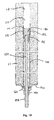
- FIG. 10 is a cross-sectional view of the completed installation of FIG. 9 ;
- FIG. 11 is a front elevation view of a friction bolt assembly according to a second embodiment
- FIG. 12 is a fragmentary isometric view of the leading portion of the friction bolt assembly of FIG. 11 ;
- FIG. 13 is a front elevation view of a friction bolt assembly according to a third embodiment
- FIG. 14 is a side elevation view of the friction bolt assembly of FIG. 13 ;
- FIG. 15 is a cross-sectional view of the friction bolt assembly of FIG. 13 , taken at section 15 - 15 of FIG. 14 ;
- FIG. 16 is an enlarged view of detail A of FIG. 15 ;
- FIG. 17 is an enlarged view of detail B of FIG. 15 ;
- FIG. 18 is a cross-sectional view of a partially completed installation of the friction bolt assembly of FIG. 13 ;
- FIG. 19 is a cross-sectional view of the completed installation of FIG. 18 ;
- FIG. 20 is a front elevation view of a friction bolt assembly according to a fourth embodiment
- FIG. 21 is a partially cross-sectioned view of the friction bolt assembly of FIG. 20 ;
- FIG. 22 is an enlarged view of detail A of FIG. 21 ;
- FIG. 23 is an enlarged view of detail B of FIG. 21 .
- FIG. 24 is a front elevation view of a friction bolt assembly according to a fifth embodiment
- FIG. 25 is a side elevation view of the friction bolt assembly of FIG. 24 ;
- FIG. 26 is a cross-sectional view of the friction bolt assembly of FIG. 24 , taken at section 26 - 26 of FIG. 25 ;
- FIG. 27 is an enlarged view of detail A of FIG. 26 ;
- FIG. 28 is an enlarged view of detail B of FIG. 26 ;
- FIG. 29 is an isometric view of a friction bolt assembly according to a sixth embodiment.
- FIG. 30 is an enlarged cross-sectional view of the trailing end region of the friction bolt assembly of FIG. 29 ;
- FIG. 31 is a cross-sectional view of an installation of the friction bolt assembly of FIG. 29 following a rock burst or seismic event.
- a friction bolt assembly 100 according to a first embodiment is depicted in FIGS. 1 to 8 of the accompanying drawings.
- the friction bolt assembly 100 has a generally tubular friction bolt body 110 that longitudinally extends between a friction bolt body leading end 111 and a friction bolt body trailing end 112 .
- the friction bolt body 110 defines a cavity 113 longitudinally extending through the friction bolt body 110 .
- the friction bolt body 110 has a split 114 extending along the friction bolt body 110 to the friction bolt body leading end 111 to allow for radial compression of the friction bolt body 110 in the usual manner.
- the split 114 extends along the full length of the friction bolt body 110 from the friction bolt body trailing end 112 .
- the friction bolt body 110 has a tapered leading portion 115 that tapers toward the friction bolt body leading end 111 in the usual manner to enable the friction bolt body 110 to be driven into a bore hole having a smaller diameter than the constant diameter of the primary portion 116 of the friction bolt body 110 .
- a collar 117 in the general form of a torus, is welded to the friction bolt body 110 adjacent the friction bolt body trailing end 112 .
- the external diameter of the primary portion 116 of the friction bolt body 110 is approximately 47 mm
- the cross-section of the leading portion 115 of the friction bolt body 110 at the friction bolt body leading end 111 is of a reduced cross-sectional area, being the minimum cross-sectional area of the friction bolt body 110 .
- the cross-section of the leading portion 115 at the friction bolt body leading end 111 is of an oval configuration having a major axis (maximum) diameter of 40 mm and minor axis diameter of 26 mm, although it is also envisaged that the leading portion 115 at the friction bolt leading 111 may be generally circular.
- the wall thickness of the friction bolt body 110 is here approximately 3 mm.
- the friction bolt body 110 is typically formed of structural grade steel.
- the friction bolt assembly 100 further includes an elongate rod 120 longitudinally extending through the cavity 113 in the friction bolt body 110 between a rod leading end 121 and a rod trailing end 122 .
- the rod 120 is typically formed of rigid steel bar.
- An expansion element 130 is mounted on the rod 120 .
- the expansion element 130 is typically located toward the rod leading end 121 and in the embodiment depicted the expansion element 130 is located at or adjacent the rod leading end 121 .
- the expansion element 130 is threadingly mounted onto a threaded leading portion 123 of the rod 120 .
- the threaded leading portion 123 of the rod 120 is received within a blind aperture 133 extending through the expansion element trailing end 132 .
- the expansion element 130 may be mounted on the rod 120 by alternate means, such as welding, or may alternatively be integrally formed with the rod 120 .
- the expansion element 130 is in the general form of a body of revolution having a frusto-conical tapered leading surface 134 extending and tapering to a closed expansion element leading end 131 , a generally cylindrical mid-surface 135 trailing the leading surface 134 and defining the maximum diameter of the expansion element 130 and a trailing generally frusto-conical engagement surface 136 that tapers, here in a non-linear manner, from the mid-surface 135 to the expansion element trailing end 132 .
- the engagement surface 136 has a slightly concave form.
- the maximum diameter of the expansion element 130 is approximately 43 mm. This is greater than the internal diameter of the friction bolt body 110 at the friction bolt body leading end 111 and less than the maximum diameter of the friction bolt body 110 .
- the expansion element 130 may further comprise means, for at least substantially preventing rotation of the expansion element 130 relative to the friction bolt body 110 .
- the means is in the form of a surface feature of the expansion element 130 , particularly in the form of a key 137 .
- the key 137 projects from, and is integrally formed with, the engagement surface 136 and extends from the expansion element trailing end 132 to the mid-surface 135 . As shown in FIGS. 1 and 6 , the key 137 projects into the split 114 formed in the friction bolt body 110 .
- the friction bolt assembly 100 further comprises a drive head 140 mounted on the rod 120 at or adjacent the rod trailing 122 .
- the drive head 140 is in the form of an open hexagonal nut that is threadingly mounted on a threaded trailing portion 124 of the rod 120 .
- a sacrificial plastic sheathing may cover the exposed region of the threaded trailing portion 124 so as to avoid the thread of the threaded trailing portion 124 being fouled by debris during transport and handling in the mine.
- a washer 150 and load transfer fitting 160 are mounted on the threaded trailing portion 124 of the rod 120 .
- the load transfer fitting 160 has a profiled leading face 161 configured to engage and support the friction bolt body trailing end 112 and collar 117 to transfer percussive loads applied during installation, as will be discussed further below, to the friction bolt body 110 without locally damaging the friction bolt body 110 .
- a bore hole 10 is drilled into the rock face 12 of a rock strata 11 to be stabilized.
- the bore hole 210 is drilled with a standard installation rig with a drill bit having a diameter typically of 43 to 44 mm, which will typically result in a bore hole diameter of 43 to 45 mm, depending on strata type and hardness.
- the maximum diameter of the friction bolt body 110 (being approximately 47 mm in a preferred embodiment) is slightly greater than the diameter of the bore hole 10 , so as to provide for an interference fit in the usual manner, whilst the maximum diameter of the expansion element 130 , here being approximately 43 mm, is less than the maximum diameter of the friction bolt body 110 and slightly less than the diameter of the bore hole 10 such that the expansion element 130 may be readily inserted into the bore hole 10 .
- a plate washer 170 (and optionally a ball washer) is mounted on the friction bolt body 110 adjacent the collar 117 and the friction bolt assembly 100 is mounted on the installation rig, particularly with the drive head 140 being received within a mating socket of the installation rig.
- the installation rig then drives the friction bolt assembly 100 into the bore hole 10 , applying percussive force via the load transfer fitting 160 until the plate washer 170 is firmly engaged with the rock face 12 .
- the frictional forces due to the interference fit between the friction bolt body 110 and bore hole wall 13 retain the friction bolt assembly 100 in the bore hole 10 , and allow for the transfer of loads between the rock strata 11 and the friction bolt body 110 .
- Additional anchoring of the friction bolt body 110 in the bore hole 10 is achieved by way of the expansion element 130 , which provides a point anchoring effect. This is achieved by actuating the rod 120 by rotating the drive head 140 . Specifically, the drive head 140 is driven in a direction tending to advance the drive head 140 along the threaded trailing portion 124 of the rod 120 (here in an anti-clockwise direction).
- the threaded leading portion 123 of the rod 120 is provided with a like-handed thread (i.e., a thread having an identical orientation) to that of the threaded trailing portion 124 , such that rotational driving of the drive head 140 does not tend to rotate the rod 120 in a direction that would withdraw the leading portion 123 of the rod 120 from the recess 133 in the expansion element 130 .
- a like-handed thread i.e., a thread having an identical orientation
- Rotation of the rod 120 and the expansion element 130 is substantially prevented by virtue of the key 137 in the manner described above.
- Rotation of the drive head 140 accordingly draws the threaded trailing portion 124 of the rod 120 through the drive head 140 and also draws the expansion element 130 toward the friction bolt body trailing end 112 , into the cavity 113 .
- the engagement surface 136 of the expansion element 130 accordingly engages the friction bolt body 110 at the friction bolt body leading end 111 and radially outwardly deforms the friction bolt body 110 at the friction bolt body leading end 111 as shown in FIG. 10 .
- the expansion element 130 is drawn fully into the tapered leading portion 115 of the friction bolt body 110 , which is radially outwardly deformed by both the engagement surface 136 and mid-surface 135 of the expansion element 130 , bearing the leading portion 115 of the friction bolt body 110 against the bore hole 10 , thereby point anchoring the friction bolt body 110 within the bore hole 10 .
- a friction bolt assembly 200 according to a second embodiment is depicted in FIGS. 11 and 12 of the accompanying drawings.
- Features of the friction bolt assembly 200 that are identical to those of the friction bolt assembly 100 of the first embodiment are provided with identical reference numerals, whilst equivalent or alternate features of the friction bolt assembly 200 are provided with reference numerals equivalent to those of the friction bolt assembly 100 of the first embodiment, incremented by 100.
- the friction bolt assembly 200 is identical to the friction bolt assembly 100 , apart from the means provided for at least substantially preventing rotation of the expansion element 230 relative to the friction bolt body 110 .
- the expansion element 230 is fixed to the friction bolt body 110 by way of one or more tack welds 237 .
- the tack welds 237 fix the engagement surface 136 directly to the friction bolt body leading end 111 .
- the welds 237 ensure that the expansion element 130 is retained in an engaged relationship with the friction bolt leading end 111 during transport and handling.
- the friction bolt assembly 200 is installed in the same manner as the friction bolt assembly 100 of the first embodiment as described above.
- the rod 120 and expansion element 230 are initially prevented from rotating relative to the friction bolt body 110 by virtue of the welds 237 .
- tension in the rod 120 and accordingly the load acting on the welds 237 increases until the welds 237 fail.
- the tension developed in the rod 120 will be sufficient to provide a firm engagement of the tapered engagement surface 136 of the expansion element 130 with the friction bolt body leading end 111 , sufficient to prevent rotation of the expansion element 130 as the drive head 140 is further rotationally driven. Accordingly, as with the key 137 of the friction bolt assembly 100 of the first embodiment, assurance is given to the operator that the expansion element 130 is engaging and radially expanding friction bolt body 110 , rather than merely freely rotating as the drive head 140 is driven.
- a friction bolt assembly 300 according to a third embodiment is depicted in FIGS. 13 to 17 . Again, features of the friction bolt assembly 300 that are identical to those of the friction bolt assembly 100 of the first embodiment are provided with identical reference numerals, whilst equivalent or alternate features are provided with equivalent reference numerals, incremented by 200.
- the friction bolt assembly 300 is similar to the friction bolt assembly 100 of the first embodiment, except that, rather than having a drive head 140 threadingly mounted on a rod 120 , and expansion element 130 effectively fixed in relation the rod 120 , in the friction bolt assembly 300 the drive head 340 is fixed in relation to the rod 320 whilst the expansion element 330 is threadingly mounted on the rod 330 .
- the friction bolt body 110 of the friction bolt assembly 300 is identical to that of the friction bolt assembly 100 .
- the expansion element 330 is identical to the expansion element 130 of the friction bolt assembly 100 of the first embodiment, except that the threaded aperture 333 extends through the full length of the expansion element 330 through the expansion element leading end 331 .
- the threaded leading portion 323 of the rod 320 is of an increased length to provide for displacement of the threaded leading portion 323 through the expansion element 330 during installation, as will be described below.
- a sacrificial plastic sheathing may cover the exposed region of the threaded leading portion 323 so as to avoid the thread of the threaded leading portion 323 being fouled by debris during transport and handling in the mine
- the drive head 340 is in the form of a blind hexagonal nut that is threadingly mounted on a shorter threaded trailing portion 324 of the rod 320 .
- the drive head 340 is mounted on the threaded trailing portion 324 of the rod 320 in a manner that results in the trailing portion 324 of the rod 320 engaging the blind end of the drive head 340 during driving of the drive head 340 during installation, such that the drive head 340 effectively remains fixed in relation to the rod 320 .
- the drive head 340 may be mounted on the rod 320 by alternate means, such as welding, or may alternatively be integrally formed with the rod 320 .
- a washer 150 and load transfer fitting 160 are mounted on the rod 320 between the drive head 340 and the friction bolt body trailing end 112 .
- a bore hole 10 is first drilled into the rock face 12 of the rock strata 11 to be stabilized, in the same manner as described above in relation to the first embodiment.
- the friction bolt assembly 300 is then installed into the bore hole 10 utilizing an installation rig in the same general manner as described above, firstly applying percussive force by the drive head 340 to drive the friction bolt assembly 300 into the bore hole 10 until the plate washer 170 is firmly engaged with the rock face 12 .
- Additional anchoring of the friction bolt body 110 in the bore hole 10 is then again achieved by way of the expansion element 330 by actuating the rod 320 by rotating the drive head 340 .
- Rotation of the drive head 340 rotates the rod 320 .
- Rotation of the expansion element 330 is again at least substantially prevented by way of the key 137 (or alternatively by way of welds 237 , as described in relation to the second embodiment).
- rotation of the rod 320 draws the expansion element 330 along the threaded leading portion 323 of the rod 320 toward the friction bolt body trailing end 112 into the cavity 113 , as depicted in FIG. 19 .
- the engagement surface 136 again engages the friction bolt body 110 and radially outwardly deforms the tapered leading end portion 115 of the friction bolt body 110 , bearing against the bore hole wall 13 to provide a point anchoring effect.
- the configuration of the friction bolt assembly 300 avoids the overhang of the rod 120 from the drive head 140 that occurs with the friction bolt assembly 100 of the first embodiment, thereby providing a lower profile installation which may be of importance for low mine ceiling heights. Instead, the threaded leading portion 323 of the rod 320 protrudes beyond the expansion element 330 .
- a friction bolt assembly 400 according to a fourth embodiment is depicted in FIGS. 20 to 23 .
- Features of the friction bolt assembly 400 that are identical to those of the friction bolt assembly 300 of the third embodiment are provided with identical reference numerals.
- the friction bolt assembly 400 of the fourth embodiment is identical to the friction bolt assembly 300 of the third embodiment, except that a coarsely threaded bar 480 is fixed to the trailing face of the drive head 340 , and extends longitudinally therefrom.
- the threaded bar 480 may be fixed to the trailing face of the drive head 340 by welding, although it is also envisaged the coarsely threaded bar may be fixed by other means, included by threaded engagement with a mating internal thread formed in the rear of the drive head 340 .
- the coarsely threaded bar 480 allows for securing of a roof mesh to the friction bolt assembly 400 after installation in the same manner that a roof mesh may be secured to the protruding threaded trailing portion 124 of the rod 120 of the friction bolt assembly 100 of the first embodiment. Installation of the friction bolt assembly 400 is identical to that described above in relation to the friction bolt assembly 300 of the first embodiment.
- a friction bolt assembly 500 according to a fifth embodiment is depicted in FIGS. 24 to 28 .
- Features of the friction bolt assembly 500 that are identical to those of the friction bolt assemblies as described above are provided with identical reference numerals. Equivalent or alternate features are provided with reference numerals equivalent to those set out above, incremented accordingly.
- the friction bolt assembly 500 is similar to the friction bolt assembly 300 of the third embodiment except that, rather than having the drive head 540 fixed in relation to the rod 520 , the drive head 540 is in the form of an open hexagonal nut that is threadingly mounted on a threaded trailing portion 524 of the rod 520 in the same manner as the drive head 140 of the friction bolt assembly 100 of the first embodiment.
- the threaded leading portion 523 and threaded trailing portion 524 of the rod 520 are like handed, each having a left handed thread for installation with a standard installation rig configured to rotate in an anti-clockwise direction, although it is also envisaged that both the threaded leading portion 523 and threaded trailing portion 524 may be right handed, for installation by clockwise rotation of an installation rig.
- the expansion element 330 may be tack welded to the rod 520 adjacent the rod leading end 521 and the drive head 540 tack welded to the rod 520 adjacent the rod trailing end 522 .
- the tack welds would then fail during rotation of the expansion element 330 and drive head 540 relative to the rod 520 during installation.
- the thread of the threaded leading portion 523 and threaded trailing portion 524 of the rod 520 may be crimped or otherwise deformed adjacent to the rod leading and trailing ends 521 , 522 respectively.
- the expansion element 330 and drive head 540 may then be reverse threaded to abut against the crimp to temporarily lock the expansion element 330 /drive head 540 to the rod 520 and specifically prevent the expansion element 330 and drive head 540 from unscrewing off the rod 520 during transport and handling.
- heat shrink material may be applied over the expansion element 330 and adjacent portion of the threaded leading portion 523 of the rod 520 , both to protect the expansion element 330 during transport and any rough handling and also to secure the expansion element 330 on the rod 520 . During installation, the heat shrink would be torn away by rotation of the rod 520 , allowing relative movement between the expansion head 330 and rod 520 .
- the drive head 540 may be driven along the threaded trailing portion 524 of the rod 520 sufficiently to provide a light pretension of the rod 520 , forcibly engaging the expansion element 530 and drive head 540 with the rod leading and trailing ends 521 , 522 respectively.
- the drive head 540 is provided with a coarse thread 541 on its hexagonal drive faces to allow for securing of a roof mesh to the friction bolt assembly 500 after installation in the same manner that a roof mesh may be secured to the coarsely threaded bar 480 of the friction bolt assembly 400 of the fourth embodiment described above, or the protruding threaded trailing portion 124 of the rod 120 of the friction bolt assembly 100 of the first embodiment as described above.
- Such an externally coarsely threaded configuration of drive head may also be applied to the other embodiments described above.
- Installation of the friction bolt assembly 500 is generally as described above in relation to the friction bolt assembly 100 of the first embodiment.
- additional anchoring of the friction bolt body 110 in the bore hole is again achieved by way of the expansion element 330 providing a point anchoring effect.
- This is again achieved by actuating the rod 520 by rotation of the drive head 540 .
- the drive head 540 is driven in a direction tending to advance the drive head 540 along the threaded trailing portion 524 of the rod 520 , in an anti-clockwise direction for a left handed thread, as noted above.
- the rod leading and trailing ends 521 , 522 will tend to protrude through the open ends of the expansion element 330 and drive head 540 respectively. Protrusion of the rod trailing end 522 through the drive head 540 will provide a visual confirmation that the point anchoring of the friction bolt body 110 within the bore hole has been achieved. Given that, as opposed to the embodiments described above, the rod 520 will travel both through the expansion element 330 and the drive head 540 , the distance by which the threaded trailing portion 523 of the rod 520 protrudes from the drive head 540 upon completion of installation will generally be less than would occur with the friction bolt assembly 100 of the first embodiment described above. It is for this reason that the coarsely externally threaded form of the drive head 540 may be useful for securing a roof mesh.
- a friction bolt assembly 600 according to a sixth embodiment is depicted in FIGS. 29 to 31 .
- Features of the friction bolt assembly 600 that are identical to those of the friction bolt assemblies as described above are provided with identical reference numerals. Equivalent or alternate features are provided with reference numerals equivalent to those set out above, incremented accordingly.
- the friction bolt assembly 600 is substantially identical to the friction bolt assembly 500 of the fifth embodiment, except that the collar 117 , welded to the friction bolt body of each of the embodiments described above, is omitted.
- the friction bolt assembly 600 is installed in the same manner as described above in relation to friction bolt assembly 500 of the fifth embodiment.
- the friction bolt assembly 600 may be particularly suitable for installations where dynamic loading may result from significant rock bursts or other seismic events, as may particularly occur in hard rock mining applications. On the occurrence of such a rock burst or other seismic event, resulting in significant movement of the rock, the rock bolt assembly 600 is able to yield by allowing relative longitudinal displacement between the rod 520 and expansion element 330 .
- Such an installation is depicted in FIG. 31 , where a rock burst has resulted in a lower rock strata layer 11 a being displaced from an upper rock strata layer 11 b , to which the rock bolt assembly 600 has been point anchored by way of radially outward deformation of the friction bolt body leading end 111 through action of the expansion element 330 .
- the friction bolt body 110 is able to remain anchored to the upper rock strata layer 1 b , with the lower portion of the friction bolt body 110 passing up through the bore hole 10 within the lower rock strata layer 11 a . This is enabled by the absence of the collar 117 that would otherwise engage the rock face 12 and prevent movement of the friction bolt body 110 along the bore hole 10 .
- the rod 520 and expansion head 330 remain fixed in relation to the lower strata layer 11 a and thus displaces with the lower rock strata layer 11 a relative to the friction bolt body 110 and upper rock strata layer 11 b .
- the means for at least substantive preventing rotation of the expansion element relative to the friction bolt body may take any of various alternate forms.
- the means may include alternate surface features of the expansion element, configured to engage the friction bolt body.
- Such alternate surface features might include, for example, a roughened or knurled configuration of the engagement surface of the expansion element.
Landscapes
- Engineering & Computer Science (AREA)
- Mining & Mineral Resources (AREA)
- General Engineering & Computer Science (AREA)
- Structural Engineering (AREA)
- Life Sciences & Earth Sciences (AREA)
- General Life Sciences & Earth Sciences (AREA)
- Geochemistry & Mineralogy (AREA)
- Geology (AREA)
- Mechanical Engineering (AREA)
- Connection Of Plates (AREA)
- Dowels (AREA)
Applications Claiming Priority (5)
| Application Number | Priority Date | Filing Date | Title |
|---|---|---|---|
| AU2013902819 | 2013-07-30 | ||
| AU2013902819A AU2013902819A0 (en) | 2013-07-30 | Friction bolt assembly | |
| AU2013904972A AU2013904972A0 (en) | 2013-12-19 | Friction bolt assembly | |
| AU2013904972 | 2013-12-19 | ||
| PCT/AU2014/000757 WO2015013743A1 (fr) | 2013-07-30 | 2014-07-29 | Ensemble boulon à friction |
Publications (2)
| Publication Number | Publication Date |
|---|---|
| US20160186564A1 US20160186564A1 (en) | 2016-06-30 |
| US10066483B2 true US10066483B2 (en) | 2018-09-04 |
Family
ID=52430743
Family Applications (1)
| Application Number | Title | Priority Date | Filing Date |
|---|---|---|---|
| US14/907,909 Active US10066483B2 (en) | 2013-07-30 | 2014-07-29 | Friction bolt assembly |
Country Status (7)
| Country | Link |
|---|---|
| US (1) | US10066483B2 (fr) |
| AU (1) | AU2014295892B2 (fr) |
| CA (1) | CA2916043C (fr) |
| PL (1) | PL416170A1 (fr) |
| SE (1) | SE1551687A1 (fr) |
| WO (1) | WO2015013743A1 (fr) |
| ZA (1) | ZA201600134B (fr) |
Cited By (1)
| Publication number | Priority date | Publication date | Assignee | Title |
|---|---|---|---|---|
| US11486250B2 (en) * | 2018-05-11 | 2022-11-01 | Epiroc Drilling Tools Ab | Method of ensuring controlled failure of rock bolt bar |
Families Citing this family (20)
| Publication number | Priority date | Publication date | Assignee | Title |
|---|---|---|---|---|
| AU2014361729B2 (en) * | 2013-12-12 | 2017-11-30 | Garock Pty Ltd | Ground support apparatus and method |
| AU2016202889B2 (en) * | 2015-06-29 | 2021-08-05 | DSI Underground Australia Pty Limited | Friction bolt assembly |
| CA2989944C (fr) | 2015-07-21 | 2023-01-17 | Ncm Innovations (Pty) Ltd | Boulon d'ancrage radialement expansible |
| US10677057B2 (en) | 2015-07-21 | 2020-06-09 | Ncm Innovations (Pty) Ltd | Pneumatic drill installed rock anchor |
| US10370968B2 (en) * | 2015-11-30 | 2019-08-06 | Sandvik Intellectual Property Ab | Friction bolt |
| CA3008179C (fr) * | 2015-12-16 | 2024-01-02 | Dywidag-Systems International Pty Limited | Ensemble boulon a friction |
| WO2017120633A1 (fr) * | 2016-01-12 | 2017-07-20 | Capell Dale | Dispositif d'ancrage en un point |
| AU2016101727A4 (en) * | 2016-09-26 | 2016-11-03 | Fci Holdings Delaware, Inc. | Rock bolt |
| CN106884837B (zh) * | 2017-03-30 | 2023-09-01 | 红塔烟草(集团)有限责任公司 | 一种易取出能重复利用的膨胀螺栓 |
| EP3622163B1 (fr) * | 2017-05-07 | 2021-05-05 | Epiroc Holdings South Africa (Pty) Ltd | Ensemble boulon d'ancrage à dispositif d'arrêt de défaillance |
| EP3673151B1 (fr) * | 2017-08-22 | 2023-06-07 | Sandvik Intellectual Property AB | Boulon d'ancrage avec adaptateur d'engrènement |
| CN107387143A (zh) * | 2017-08-30 | 2017-11-24 | 成都现代万通锚固技术有限公司 | 一种摩擦固定式锚杆 |
| ES2972644T3 (es) * | 2017-11-27 | 2024-06-13 | Sandvik Intellectual Property | Perno de roca con adaptador de enganche |
| EP4242423B1 (fr) * | 2018-08-23 | 2025-04-23 | Sandvik Mining and Construction Australia (Production/Supply) Pty Ltd | Boulon d'ancrage présentant une région d'affichage d'informations |
| AU2020401402A1 (en) * | 2019-12-09 | 2022-05-26 | Innovative Mining Products (Pty) Ltd | Deformed hollow rock bolt |
| FI4027026T3 (fi) * | 2021-01-07 | 2023-04-05 | Raimund Beck Nageltechnik Gmbh | Naula, erityisesti käytettäväksi naulan kiinnityslaitteessa |
| US20220316512A1 (en) * | 2021-03-30 | 2022-10-06 | Yoke Industrial Corp. | Expansion anchoring device |
| ES3060672T3 (en) * | 2021-08-05 | 2026-03-27 | Sandvik Mining And Construction Australia Production/Supply Pty Ltd | Double-wedge rock bolt |
| EP4174284B1 (fr) | 2021-10-28 | 2024-07-31 | Sandvik Mining and Construction Australia (Production/Supply) Pty Ltd. | Boulon d'ancrage |
| TWI855724B (zh) * | 2023-06-09 | 2024-09-11 | 振鋒企業股份有限公司 | 膨脹式錨定裝置 |
Citations (55)
| Publication number | Priority date | Publication date | Assignee | Title |
|---|---|---|---|---|
| US2442113A (en) * | 1945-05-25 | 1948-05-25 | Beijl Zako Sytse | Tunnelling and like subterranean operations |
| US2673452A (en) * | 1950-04-12 | 1954-03-30 | Milton H Fies | Apparatus for installing roof suspension bolts in mines |
| US2741461A (en) * | 1950-09-07 | 1956-04-10 | Joy Mfg Co | Drill |
| US3311012A (en) * | 1965-03-11 | 1967-03-28 | Chester I Williams | Pressure-actuated expanding anchor |
| US3973409A (en) * | 1974-07-05 | 1976-08-10 | Kabushiki Kaisha Takechi Koumusho | Apparatus for establishing an anchor |
| US4056036A (en) * | 1976-03-17 | 1977-11-01 | Bergwerksverband Gmbh | Borehole anchor |
| US4140428A (en) * | 1978-03-06 | 1979-02-20 | Shakespeare Company | Tie rod support for mine |
| US4194858A (en) * | 1978-09-25 | 1980-03-25 | The Eastern Company | Mine roof bolt anchor installation |
| US4226559A (en) * | 1977-08-31 | 1980-10-07 | Atlas Copco Aktiebolag | Rock bolting apparatus |
| US4274762A (en) * | 1978-03-03 | 1981-06-23 | Frederick Johnson | Prestressed rock truss |
| US4305687A (en) * | 1979-01-26 | 1981-12-15 | Jack Parker | Anchoring system for rock bolts |
| US4313628A (en) * | 1980-05-08 | 1982-02-02 | Duenke Milton J | Coupling for hoses and similar conduits |
| US4316677A (en) * | 1980-03-07 | 1982-02-23 | Armand Ciavatta | Tubular shank device |
| US4322183A (en) * | 1980-03-07 | 1982-03-30 | Armand Ciavatta | Friction rock stabilizer and installation lubricating cement apparatus and method |
| US4344599A (en) * | 1977-12-21 | 1982-08-17 | Atlas Copco Aktiebolag | Rock drill boom structure |
| US4347020A (en) * | 1980-01-02 | 1982-08-31 | Birmingham Bolt Company | Mine roof bolt assembly |
| US4351625A (en) * | 1978-06-13 | 1982-09-28 | Linden-Alimak Ab | Apparatus for automatic bolting in rock reinforcement |
| US4398850A (en) * | 1981-02-09 | 1983-08-16 | Copper Range Company | Roof bolter and process |
| US4430025A (en) * | 1981-03-04 | 1984-02-07 | Armand Ciavatta | Oblate friction rock stabilizer and installation lubricating cement utilized therewith |
| US4437795A (en) | 1981-11-02 | 1984-03-20 | Birmingham Bolt Company | Mine roof anchor assembly |
| US4588037A (en) * | 1983-12-16 | 1986-05-13 | Envirotech Corporation | Turret for roof bolting apparatus |
| US4655643A (en) * | 1984-02-22 | 1987-04-07 | Lane William L | Rockbolt and installer wand |
| US4661022A (en) * | 1985-11-14 | 1987-04-28 | Seegmiller Ben L | Rock bolt structure and installation |
| US4708533A (en) * | 1985-11-07 | 1987-11-24 | Oy Tampella Ab | Method and a device for guiding a concrete feeding hose in connection with the grout feed in rock bolting |
| US4732509A (en) * | 1985-11-07 | 1988-03-22 | Oy Tampella Ab | Method and a device for feeding concrete into a drill hole in the concrete boiling of a rock |
| US4759888A (en) * | 1985-06-26 | 1988-07-26 | Brest Van Kempen Carel J H | Method for automatically installing and testing grouted rock bolts |
| US5076734A (en) * | 1990-10-05 | 1991-12-31 | H & S Machine And Supply Co., Inc. | Roof bolt with paddle resin mixer and method for making the same |
| US5082399A (en) * | 1988-08-08 | 1992-01-21 | Jennmar Corporation | Mine roof anchor having adjustable resin retaining washer and expansion shell assembly with friction reducing means |
| US5114279A (en) * | 1990-07-10 | 1992-05-19 | Atlas Copco Construction And Mining Technique Ab | Device for setting a rock bolt |
| US5165825A (en) * | 1990-12-03 | 1992-11-24 | Atlas Copco Construction And Mining Technique Ab | Rock bolting device |
| US5244314A (en) * | 1991-06-27 | 1993-09-14 | Jennmar Corporation | Expansion assembly |
| US5441372A (en) * | 1993-05-05 | 1995-08-15 | Premetalco, Inc. | Rock bolt shell and cone |
| US20020119014A1 (en) * | 2001-02-26 | 2002-08-29 | Coombs Perry L. | Resin nozzle positioner |
| US20040161316A1 (en) * | 2003-02-19 | 2004-08-19 | F.M. Locotos Co., Inc. | Tubular mining bolt and method |
| US20040165958A1 (en) * | 2001-04-20 | 2004-08-26 | Mclaren Matthew David | Inserter and cap |
| US20070031196A1 (en) * | 2003-10-27 | 2007-02-08 | Marcellin Bruneau | Anchor device with an elastic expansion sleeve |
| US20070141297A1 (en) * | 2003-11-07 | 2007-06-21 | Buxton Sean P | Plug member |
| US20070243026A1 (en) * | 2006-04-18 | 2007-10-18 | Mansour Mining Inc. | Detachable anchor bolt mixing head for use in mine roof support systems and method of using same |
| US20080110640A1 (en) * | 2004-12-23 | 2008-05-15 | Mark Bernthaler | Process for Setting Anchors and Anchor Which Can Be Used in This Process |
| US7381013B1 (en) * | 2002-08-02 | 2008-06-03 | Dywidag-Systems Internationalpty Limited | Rock bolt post grouting apparatus |
| US7407344B2 (en) * | 2005-06-03 | 2008-08-05 | J. H. Fletcher & Co. | Automated, low profile drilling/bolting module with roof reference guide |
| US7416033B2 (en) * | 2003-07-08 | 2008-08-26 | J.H. Fletcher & Co. | Instrumented drill head, related drilling/bolting machines, and methods |
| US7481603B1 (en) * | 2005-10-07 | 2009-01-27 | Shelter Technologies, Llc | Tensionable spiral bolt with resin nut and related method |
| US20090052995A1 (en) * | 2004-07-08 | 2009-02-26 | Atlas Copco Craelius Ab | Arrangement for injecting and affixing a reinforcing or anchoring element in a rock wall |
| US20090136302A1 (en) * | 2006-10-09 | 2009-05-28 | Fox William G | Tensionable spiral bolt with resin nut and related method |
| US7607866B2 (en) * | 2006-06-07 | 2009-10-27 | Joy Mm Delaware, Inc. | Drilling rig |
| US20110311315A1 (en) * | 2007-08-22 | 2011-12-22 | Diwidag-Systems International Pty Limited | Friction Bolt Assembly |
| US20120034036A1 (en) * | 2009-04-16 | 2012-02-09 | Gary Robert Davison | Friction stabiliser |
| WO2012071625A1 (fr) | 2010-12-01 | 2012-06-07 | Peter Andrew Gray | Ensemble écrou |
| US20120163924A1 (en) * | 2009-03-10 | 2012-06-28 | Sandvik Intellectual Property Ab | Friction bolt |
| ZA201207431B (en) | 2011-10-21 | 2013-05-29 | Innovative Mining Products (Pty) Ltd | A radially expansible rock bolt |
| US20140112724A1 (en) * | 2012-10-23 | 2014-04-24 | Yves Nelson | Rock bolting system, method of installing rock bolts, and flexible bolt centralizer |
| US20150267537A1 (en) * | 2012-10-26 | 2015-09-24 | Jurie Pretorius Smit | Rock anchoring system and method |
| US20150300171A1 (en) * | 2012-11-09 | 2015-10-22 | Gazmick Pty Ltd | Device, method and system for loading fixatives for rock bolts |
| US20160115789A1 (en) * | 2013-06-26 | 2016-04-28 | Atlas Copco Rock Drills Ab | Arrangement And Method For Positioning Cartridges For A Rock Grouting Equipment |
-
2014
- 2014-07-29 WO PCT/AU2014/000757 patent/WO2015013743A1/fr not_active Ceased
- 2014-07-29 PL PL416170A patent/PL416170A1/pl unknown
- 2014-07-29 SE SE1551687A patent/SE1551687A1/sv not_active Application Discontinuation
- 2014-07-29 AU AU2014295892A patent/AU2014295892B2/en active Active
- 2014-07-29 US US14/907,909 patent/US10066483B2/en active Active
- 2014-07-29 CA CA2916043A patent/CA2916043C/fr active Active
-
2016
- 2016-01-07 ZA ZA2016/00134A patent/ZA201600134B/en unknown
Patent Citations (56)
| Publication number | Priority date | Publication date | Assignee | Title |
|---|---|---|---|---|
| US2442113A (en) * | 1945-05-25 | 1948-05-25 | Beijl Zako Sytse | Tunnelling and like subterranean operations |
| US2673452A (en) * | 1950-04-12 | 1954-03-30 | Milton H Fies | Apparatus for installing roof suspension bolts in mines |
| US2741461A (en) * | 1950-09-07 | 1956-04-10 | Joy Mfg Co | Drill |
| US3311012A (en) * | 1965-03-11 | 1967-03-28 | Chester I Williams | Pressure-actuated expanding anchor |
| US3973409A (en) * | 1974-07-05 | 1976-08-10 | Kabushiki Kaisha Takechi Koumusho | Apparatus for establishing an anchor |
| US4056036A (en) * | 1976-03-17 | 1977-11-01 | Bergwerksverband Gmbh | Borehole anchor |
| US4226559A (en) * | 1977-08-31 | 1980-10-07 | Atlas Copco Aktiebolag | Rock bolting apparatus |
| US4344599A (en) * | 1977-12-21 | 1982-08-17 | Atlas Copco Aktiebolag | Rock drill boom structure |
| US4274762A (en) * | 1978-03-03 | 1981-06-23 | Frederick Johnson | Prestressed rock truss |
| US4140428A (en) * | 1978-03-06 | 1979-02-20 | Shakespeare Company | Tie rod support for mine |
| US4351625A (en) * | 1978-06-13 | 1982-09-28 | Linden-Alimak Ab | Apparatus for automatic bolting in rock reinforcement |
| US4194858A (en) * | 1978-09-25 | 1980-03-25 | The Eastern Company | Mine roof bolt anchor installation |
| US4305687A (en) * | 1979-01-26 | 1981-12-15 | Jack Parker | Anchoring system for rock bolts |
| US4347020A (en) * | 1980-01-02 | 1982-08-31 | Birmingham Bolt Company | Mine roof bolt assembly |
| US4316677A (en) * | 1980-03-07 | 1982-02-23 | Armand Ciavatta | Tubular shank device |
| US4322183A (en) * | 1980-03-07 | 1982-03-30 | Armand Ciavatta | Friction rock stabilizer and installation lubricating cement apparatus and method |
| US4313628A (en) * | 1980-05-08 | 1982-02-02 | Duenke Milton J | Coupling for hoses and similar conduits |
| US4398850A (en) * | 1981-02-09 | 1983-08-16 | Copper Range Company | Roof bolter and process |
| US4430025A (en) * | 1981-03-04 | 1984-02-07 | Armand Ciavatta | Oblate friction rock stabilizer and installation lubricating cement utilized therewith |
| US4437795A (en) | 1981-11-02 | 1984-03-20 | Birmingham Bolt Company | Mine roof anchor assembly |
| US4588037A (en) * | 1983-12-16 | 1986-05-13 | Envirotech Corporation | Turret for roof bolting apparatus |
| US4655643A (en) * | 1984-02-22 | 1987-04-07 | Lane William L | Rockbolt and installer wand |
| US4759888A (en) * | 1985-06-26 | 1988-07-26 | Brest Van Kempen Carel J H | Method for automatically installing and testing grouted rock bolts |
| US4708533A (en) * | 1985-11-07 | 1987-11-24 | Oy Tampella Ab | Method and a device for guiding a concrete feeding hose in connection with the grout feed in rock bolting |
| US4732509A (en) * | 1985-11-07 | 1988-03-22 | Oy Tampella Ab | Method and a device for feeding concrete into a drill hole in the concrete boiling of a rock |
| US4661022A (en) * | 1985-11-14 | 1987-04-28 | Seegmiller Ben L | Rock bolt structure and installation |
| US5082399A (en) * | 1988-08-08 | 1992-01-21 | Jennmar Corporation | Mine roof anchor having adjustable resin retaining washer and expansion shell assembly with friction reducing means |
| US5114279A (en) * | 1990-07-10 | 1992-05-19 | Atlas Copco Construction And Mining Technique Ab | Device for setting a rock bolt |
| US5076734A (en) * | 1990-10-05 | 1991-12-31 | H & S Machine And Supply Co., Inc. | Roof bolt with paddle resin mixer and method for making the same |
| US5165825A (en) * | 1990-12-03 | 1992-11-24 | Atlas Copco Construction And Mining Technique Ab | Rock bolting device |
| US5244314A (en) * | 1991-06-27 | 1993-09-14 | Jennmar Corporation | Expansion assembly |
| US5441372A (en) * | 1993-05-05 | 1995-08-15 | Premetalco, Inc. | Rock bolt shell and cone |
| US20020119014A1 (en) * | 2001-02-26 | 2002-08-29 | Coombs Perry L. | Resin nozzle positioner |
| US6447210B1 (en) * | 2001-02-26 | 2002-09-10 | Oldenburg Cannon, Inc. | Resin nozzle positioner |
| US20040165958A1 (en) * | 2001-04-20 | 2004-08-26 | Mclaren Matthew David | Inserter and cap |
| US7381013B1 (en) * | 2002-08-02 | 2008-06-03 | Dywidag-Systems Internationalpty Limited | Rock bolt post grouting apparatus |
| US20040161316A1 (en) * | 2003-02-19 | 2004-08-19 | F.M. Locotos Co., Inc. | Tubular mining bolt and method |
| US7416033B2 (en) * | 2003-07-08 | 2008-08-26 | J.H. Fletcher & Co. | Instrumented drill head, related drilling/bolting machines, and methods |
| US20070031196A1 (en) * | 2003-10-27 | 2007-02-08 | Marcellin Bruneau | Anchor device with an elastic expansion sleeve |
| US20070141297A1 (en) * | 2003-11-07 | 2007-06-21 | Buxton Sean P | Plug member |
| US20090052995A1 (en) * | 2004-07-08 | 2009-02-26 | Atlas Copco Craelius Ab | Arrangement for injecting and affixing a reinforcing or anchoring element in a rock wall |
| US20080110640A1 (en) * | 2004-12-23 | 2008-05-15 | Mark Bernthaler | Process for Setting Anchors and Anchor Which Can Be Used in This Process |
| US7407344B2 (en) * | 2005-06-03 | 2008-08-05 | J. H. Fletcher & Co. | Automated, low profile drilling/bolting module with roof reference guide |
| US7481603B1 (en) * | 2005-10-07 | 2009-01-27 | Shelter Technologies, Llc | Tensionable spiral bolt with resin nut and related method |
| US20070243026A1 (en) * | 2006-04-18 | 2007-10-18 | Mansour Mining Inc. | Detachable anchor bolt mixing head for use in mine roof support systems and method of using same |
| US7607866B2 (en) * | 2006-06-07 | 2009-10-27 | Joy Mm Delaware, Inc. | Drilling rig |
| US20090136302A1 (en) * | 2006-10-09 | 2009-05-28 | Fox William G | Tensionable spiral bolt with resin nut and related method |
| US20110311315A1 (en) * | 2007-08-22 | 2011-12-22 | Diwidag-Systems International Pty Limited | Friction Bolt Assembly |
| US20120163924A1 (en) * | 2009-03-10 | 2012-06-28 | Sandvik Intellectual Property Ab | Friction bolt |
| US20120034036A1 (en) * | 2009-04-16 | 2012-02-09 | Gary Robert Davison | Friction stabiliser |
| WO2012071625A1 (fr) | 2010-12-01 | 2012-06-07 | Peter Andrew Gray | Ensemble écrou |
| ZA201207431B (en) | 2011-10-21 | 2013-05-29 | Innovative Mining Products (Pty) Ltd | A radially expansible rock bolt |
| US20140112724A1 (en) * | 2012-10-23 | 2014-04-24 | Yves Nelson | Rock bolting system, method of installing rock bolts, and flexible bolt centralizer |
| US20150267537A1 (en) * | 2012-10-26 | 2015-09-24 | Jurie Pretorius Smit | Rock anchoring system and method |
| US20150300171A1 (en) * | 2012-11-09 | 2015-10-22 | Gazmick Pty Ltd | Device, method and system for loading fixatives for rock bolts |
| US20160115789A1 (en) * | 2013-06-26 | 2016-04-28 | Atlas Copco Rock Drills Ab | Arrangement And Method For Positioning Cartridges For A Rock Grouting Equipment |
Non-Patent Citations (3)
| Title |
|---|
| International Search Report dated Aug. 26, 2014 from corresponding PCT/AU2014/000757, 8 pages. |
| Notification of Material Filed Under Section 27 dated Mar. 29, 2016 from corresponding Australian Application No. 2014295892, 5 pages. |
| Written Opinion dated Aug. 26, 2014 from corresponding PCT/AU2014/000757, 6 pages. |
Cited By (1)
| Publication number | Priority date | Publication date | Assignee | Title |
|---|---|---|---|---|
| US11486250B2 (en) * | 2018-05-11 | 2022-11-01 | Epiroc Drilling Tools Ab | Method of ensuring controlled failure of rock bolt bar |
Also Published As
| Publication number | Publication date |
|---|---|
| ZA201600134B (en) | 2019-01-30 |
| WO2015013743A1 (fr) | 2015-02-05 |
| AU2014295892A1 (en) | 2016-01-21 |
| AU2014295892B2 (en) | 2018-07-19 |
| US20160186564A1 (en) | 2016-06-30 |
| SE1551687A1 (sv) | 2015-12-21 |
| PL416170A1 (pl) | 2016-08-16 |
| CA2916043C (fr) | 2021-11-09 |
| CA2916043A1 (fr) | 2015-02-05 |
Similar Documents
| Publication | Publication Date | Title |
|---|---|---|
| US10066483B2 (en) | Friction bolt assembly | |
| US8714883B2 (en) | Friction bolt | |
| US10677057B2 (en) | Pneumatic drill installed rock anchor | |
| CA3008179C (fr) | Ensemble boulon a friction | |
| AU2022204855B2 (en) | A Point Anchoring Device | |
| AU2019203951A1 (en) | Pneumatic Drill Installed Rock Anchor | |
| CN113167113B (zh) | 具有信息显示区域的岩栓 | |
| AU2019202781B2 (en) | Friction bolt assembly | |
| AU2016202889B2 (en) | Friction bolt assembly | |
| AU2018390988A1 (en) | Friction bolt | |
| AU2012101962A4 (en) | Rock bolt | |
| AU2017204341B2 (en) | Tensioning assembly for a cable bolt | |
| AU2014203600A1 (en) | Rock bolt assembly | |
| AU2014215939A1 (en) | Tensioning system and assembly for a cable bolt |
Legal Events
| Date | Code | Title | Description |
|---|---|---|---|
| AS | Assignment |
Owner name: DYWIDAG-SYSTEMS INTERNATIONAL PTY LIMITED, AUSTRAL Free format text: ASSIGNMENT OF ASSIGNORS INTEREST;ASSIGNORS:EVANS, DAVID WILLIAM;HIRD, DEREK COLIN;REEL/FRAME:037595/0877 Effective date: 20160127 |
|
| STCF | Information on status: patent grant |
Free format text: PATENTED CASE |
|
| MAFP | Maintenance fee payment |
Free format text: PAYMENT OF MAINTENANCE FEE, 4TH YEAR, LARGE ENTITY (ORIGINAL EVENT CODE: M1551); ENTITY STATUS OF PATENT OWNER: LARGE ENTITY Year of fee payment: 4 |
|
| AS | Assignment |
Owner name: DSI UNDERGROUND AUSTRALIA PTY LIMITED, AUSTRALIA Free format text: CHANGE OF NAME;ASSIGNOR:DYWIDAG-SYSTEMS INTERNATIONAL PTY LIMITED;REEL/FRAME:062497/0342 Effective date: 20210913 |
|
| MAFP | Maintenance fee payment |
Free format text: PAYMENT OF MAINTENANCE FEE, 8TH YEAR, LARGE ENTITY (ORIGINAL EVENT CODE: M1552); ENTITY STATUS OF PATENT OWNER: LARGE ENTITY Year of fee payment: 8 |