US10076297B2 - Phase contrast X-ray tomography device - Google Patents
Phase contrast X-ray tomography device Download PDFInfo
- Publication number
- US10076297B2 US10076297B2 US14/387,786 US201314387786A US10076297B2 US 10076297 B2 US10076297 B2 US 10076297B2 US 201314387786 A US201314387786 A US 201314387786A US 10076297 B2 US10076297 B2 US 10076297B2
- Authority
- US
- United States
- Prior art keywords
- ray
- phase contrast
- tomography device
- phase
- grating
- Prior art date
- Legal status (The legal status is an assumption and is not a legal conclusion. Google has not performed a legal analysis and makes no representation as to the accuracy of the status listed.)
- Active, expires
Links
Images




Classifications
-
- A—HUMAN NECESSITIES
- A61—MEDICAL OR VETERINARY SCIENCE; HYGIENE
- A61B—DIAGNOSIS; SURGERY; IDENTIFICATION
- A61B6/00—Apparatus or devices for radiation diagnosis; Apparatus or devices for radiation diagnosis combined with radiation therapy equipment
- A61B6/48—Diagnostic techniques
- A61B6/484—Diagnostic techniques involving phase contrast X-ray imaging
-
- A—HUMAN NECESSITIES
- A61—MEDICAL OR VETERINARY SCIENCE; HYGIENE
- A61B—DIAGNOSIS; SURGERY; IDENTIFICATION
- A61B6/00—Apparatus or devices for radiation diagnosis; Apparatus or devices for radiation diagnosis combined with radiation therapy equipment
- A61B6/02—Arrangements for diagnosis sequentially in different planes; Stereoscopic radiation diagnosis
- A61B6/03—Computed tomography [CT]
- A61B6/032—Transmission computed tomography [CT]
-
- A—HUMAN NECESSITIES
- A61—MEDICAL OR VETERINARY SCIENCE; HYGIENE
- A61B—DIAGNOSIS; SURGERY; IDENTIFICATION
- A61B6/00—Apparatus or devices for radiation diagnosis; Apparatus or devices for radiation diagnosis combined with radiation therapy equipment
- A61B6/02—Arrangements for diagnosis sequentially in different planes; Stereoscopic radiation diagnosis
- A61B6/03—Computed tomography [CT]
- A61B6/032—Transmission computed tomography [CT]
- A61B6/035—Mechanical aspects of CT
-
- A—HUMAN NECESSITIES
- A61—MEDICAL OR VETERINARY SCIENCE; HYGIENE
- A61B—DIAGNOSIS; SURGERY; IDENTIFICATION
- A61B6/00—Apparatus or devices for radiation diagnosis; Apparatus or devices for radiation diagnosis combined with radiation therapy equipment
- A61B6/40—Arrangements for generating radiation specially adapted for radiation diagnosis
- A61B6/4021—Arrangements for generating radiation specially adapted for radiation diagnosis involving movement of the focal spot
-
- A—HUMAN NECESSITIES
- A61—MEDICAL OR VETERINARY SCIENCE; HYGIENE
- A61B—DIAGNOSIS; SURGERY; IDENTIFICATION
- A61B6/00—Apparatus or devices for radiation diagnosis; Apparatus or devices for radiation diagnosis combined with radiation therapy equipment
- A61B6/40—Arrangements for generating radiation specially adapted for radiation diagnosis
- A61B6/4021—Arrangements for generating radiation specially adapted for radiation diagnosis involving movement of the focal spot
- A61B6/4028—Arrangements for generating radiation specially adapted for radiation diagnosis involving movement of the focal spot resulting in acquisition of views from substantially different positions, e.g. EBCT
-
- A—HUMAN NECESSITIES
- A61—MEDICAL OR VETERINARY SCIENCE; HYGIENE
- A61B—DIAGNOSIS; SURGERY; IDENTIFICATION
- A61B6/00—Apparatus or devices for radiation diagnosis; Apparatus or devices for radiation diagnosis combined with radiation therapy equipment
- A61B6/40—Arrangements for generating radiation specially adapted for radiation diagnosis
- A61B6/4035—Arrangements for generating radiation specially adapted for radiation diagnosis the source being combined with a filter or grating
-
- A—HUMAN NECESSITIES
- A61—MEDICAL OR VETERINARY SCIENCE; HYGIENE
- A61B—DIAGNOSIS; SURGERY; IDENTIFICATION
- A61B6/00—Apparatus or devices for radiation diagnosis; Apparatus or devices for radiation diagnosis combined with radiation therapy equipment
- A61B6/40—Arrangements for generating radiation specially adapted for radiation diagnosis
- A61B6/4064—Arrangements for generating radiation specially adapted for radiation diagnosis specially adapted for producing a particular type of beam
- A61B6/4085—Cone-beams
-
- A—HUMAN NECESSITIES
- A61—MEDICAL OR VETERINARY SCIENCE; HYGIENE
- A61B—DIAGNOSIS; SURGERY; IDENTIFICATION
- A61B6/00—Apparatus or devices for radiation diagnosis; Apparatus or devices for radiation diagnosis combined with radiation therapy equipment
- A61B6/42—Arrangements for detecting radiation specially adapted for radiation diagnosis
- A61B6/4208—Arrangements for detecting radiation specially adapted for radiation diagnosis characterised by using a particular type of detector
- A61B6/4233—Arrangements for detecting radiation specially adapted for radiation diagnosis characterised by using a particular type of detector using matrix detectors
-
- A—HUMAN NECESSITIES
- A61—MEDICAL OR VETERINARY SCIENCE; HYGIENE
- A61B—DIAGNOSIS; SURGERY; IDENTIFICATION
- A61B6/00—Apparatus or devices for radiation diagnosis; Apparatus or devices for radiation diagnosis combined with radiation therapy equipment
- A61B6/44—Constructional features of apparatus for radiation diagnosis
- A61B6/4429—Constructional features of apparatus for radiation diagnosis related to the mounting of source units and detector units
- A61B6/4435—Constructional features of apparatus for radiation diagnosis related to the mounting of source units and detector units the source unit and the detector unit being coupled by a rigid structure
-
- A—HUMAN NECESSITIES
- A61—MEDICAL OR VETERINARY SCIENCE; HYGIENE
- A61B—DIAGNOSIS; SURGERY; IDENTIFICATION
- A61B6/00—Apparatus or devices for radiation diagnosis; Apparatus or devices for radiation diagnosis combined with radiation therapy equipment
- A61B6/44—Constructional features of apparatus for radiation diagnosis
- A61B6/4429—Constructional features of apparatus for radiation diagnosis related to the mounting of source units and detector units
- A61B6/4435—Constructional features of apparatus for radiation diagnosis related to the mounting of source units and detector units the source unit and the detector unit being coupled by a rigid structure
- A61B6/4441—Constructional features of apparatus for radiation diagnosis related to the mounting of source units and detector units the source unit and the detector unit being coupled by a rigid structure the rigid structure being a C-arm or U-arm
-
- G—PHYSICS
- G01—MEASURING; TESTING
- G01N—INVESTIGATING OR ANALYSING MATERIALS BY DETERMINING THEIR CHEMICAL OR PHYSICAL PROPERTIES
- G01N23/00—Investigating or analysing materials by the use of wave or particle radiation, e.g. X-rays or neutrons, not covered by groups G01N3/00 – G01N17/00, G01N21/00 or G01N22/00
- G01N23/02—Investigating or analysing materials by the use of wave or particle radiation, e.g. X-rays or neutrons, not covered by groups G01N3/00 – G01N17/00, G01N21/00 or G01N22/00 by transmitting the radiation through the material
- G01N23/04—Investigating or analysing materials by the use of wave or particle radiation, e.g. X-rays or neutrons, not covered by groups G01N3/00 – G01N17/00, G01N21/00 or G01N22/00 by transmitting the radiation through the material and forming images of the material
- G01N23/046—Investigating or analysing materials by the use of wave or particle radiation, e.g. X-rays or neutrons, not covered by groups G01N3/00 – G01N17/00, G01N21/00 or G01N22/00 by transmitting the radiation through the material and forming images of the material using tomography, e.g. computed tomography [CT]
-
- G—PHYSICS
- G01—MEASURING; TESTING
- G01N—INVESTIGATING OR ANALYSING MATERIALS BY DETERMINING THEIR CHEMICAL OR PHYSICAL PROPERTIES
- G01N23/00—Investigating or analysing materials by the use of wave or particle radiation, e.g. X-rays or neutrons, not covered by groups G01N3/00 – G01N17/00, G01N21/00 or G01N22/00
- G01N23/20—Investigating or analysing materials by the use of wave or particle radiation, e.g. X-rays or neutrons, not covered by groups G01N3/00 – G01N17/00, G01N21/00 or G01N22/00 by using diffraction of the radiation by the materials, e.g. for investigating crystal structure; by using scattering of the radiation by the materials, e.g. for investigating non-crystalline materials; by using reflection of the radiation by the materials
- G01N23/20075—Investigating or analysing materials by the use of wave or particle radiation, e.g. X-rays or neutrons, not covered by groups G01N3/00 – G01N17/00, G01N21/00 or G01N22/00 by using diffraction of the radiation by the materials, e.g. for investigating crystal structure; by using scattering of the radiation by the materials, e.g. for investigating non-crystalline materials; by using reflection of the radiation by the materials by measuring interferences of X-rays, e.g. Borrmann effect
-
- G—PHYSICS
- G21—NUCLEAR PHYSICS; NUCLEAR ENGINEERING
- G21K—HANDLING OF PARTICLES OR IONISING RADIATION NOT OTHERWISE PROVIDED FOR; IRRADIATION DEVICES; GAMMA RAY OR X-RAY MICROSCOPES
- G21K1/00—Arrangements for handling particles or ionising radiation, e.g. focusing or moderating
- G21K1/06—Arrangements for handling particles or ionising radiation, e.g. focusing or moderating using diffraction, refraction or reflection, e.g. monochromators
- G21K1/067—Arrangements for handling particles or ionising radiation, e.g. focusing or moderating using diffraction, refraction or reflection, e.g. monochromators using surface reflection, e.g. grazing incidence mirrors, gratings
-
- H—ELECTRICITY
- H05—ELECTRIC TECHNIQUES NOT OTHERWISE PROVIDED FOR
- H05G—X-RAY TECHNIQUE
- H05G1/00—X-ray apparatus involving X-ray tubes; Circuits therefor
- H05G1/08—Electrical details
- H05G1/26—Measuring, controlling or protecting
- H05G1/30—Controlling
-
- A—HUMAN NECESSITIES
- A61—MEDICAL OR VETERINARY SCIENCE; HYGIENE
- A61B—DIAGNOSIS; SURGERY; IDENTIFICATION
- A61B6/00—Apparatus or devices for radiation diagnosis; Apparatus or devices for radiation diagnosis combined with radiation therapy equipment
- A61B6/54—Control of apparatus or devices for radiation diagnosis
- A61B6/548—Remote control of the apparatus or devices
-
- G—PHYSICS
- G21—NUCLEAR PHYSICS; NUCLEAR ENGINEERING
- G21K—HANDLING OF PARTICLES OR IONISING RADIATION NOT OTHERWISE PROVIDED FOR; IRRADIATION DEVICES; GAMMA RAY OR X-RAY MICROSCOPES
- G21K2201/00—Arrangements for handling radiation or particles
- G21K2201/06—Arrangements for handling radiation or particles using diffractive, refractive or reflecting elements
- G21K2201/067—Construction details
-
- G—PHYSICS
- G21—NUCLEAR PHYSICS; NUCLEAR ENGINEERING
- G21K—HANDLING OF PARTICLES OR IONISING RADIATION NOT OTHERWISE PROVIDED FOR; IRRADIATION DEVICES; GAMMA RAY OR X-RAY MICROSCOPES
- G21K2207/00—Particular details of imaging devices or methods using ionizing electromagnetic radiation such as X-rays or gamma rays
- G21K2207/005—Methods and devices obtaining contrast from non-absorbing interaction of the radiation with matter, e.g. phase contrast
Definitions
- the invention relates to a phase contrast x-ray tomography device.
- Objects can be detected in radiography both by the fact that the incident radiation in the object is weakened, or else by the fact that the incident radiation in the object has a different velocity of propagation than outside the same.
- the above also applies to the detection of structures within an object.
- Typical methods for detecting the change of phase positions consist in using the light which has passed through the object to generate interference figures and measuring their brightness distribution with suitable detectors.
- Such detectors are today, in particular, row detectors which have a large number of detection pixels following one another at close spacing regularly in the detector longitudinal direction.
- the output signals of such detectors can be shaped and evaluated by applying known techniques.
- strip detectors which have detector elements following one another regularly at a small spacing in a direction perpendicular to the detector longitudinal direction, the number of which however is less than in the detector longitudinal direction, the interference figures can also be evaluated in a second direction, with the result that the quality of the image can be improved or the time required for capturing the image can be reduced.
- row detectors are to be understood here also as strip detectors, in order to avoid duplicate mentions.
- phase contrast method Since a high-contrast representation of the object is derived from phase differences in the position of the wavefronts.
- Phase contrast methods are of great interest in particular where materials absorb light only a little, i.e. are largely transparent to the light used.
- DE 10 2006 046 034 A1 also published as U.S. Pat. No. 7,532,704 B2
- a phase contrast x-ray tomography device which operates according to the principle described at the outset.
- the interference pattern is generated by two x-ray gratings arranged at different spacing in alignment in front of a linear detector.
- DE 10 2006 046 034 A1 is concerned with providing a phase contrast x-ray tomography device which can be used at the same time also for conventional radiograms which are based on the different absorption of the x-rays in different regions of the examination object.
- an x-ray source and a phase measuring device are arranged on a circular guide (gantry) diametrically opposite one another. They rotate in a rigid relative position about the axis of the gantry. This axis is also referred to below simply as the device axis.
- a body e.g. a patient
- the x-ray beam used for the irradiation has only small dimensions in the direction of the device axis, i.e. has the shape of a very flat fan.
- a layer of the object to be examined is thus acquired. Owing to the fact that a relative movement between the gantry and the object to be examined is produced in the axial direction, a large number of closely adjacent sections through the object can be created.
- phase contrast x-ray computer tomography x-ray gratings with very small grating constants must be used in the phase measuring device. These x-ray gratings must be positioned extremely accurately and moreover also displaced very precisely by small distances in order to produce specific small changes in the interference patterns which are important for the evaluation of the interference patterns. Consequently, the known tomography device must have a very stable structure, in order to reliably exclude vibration-induced or distortion-induced changes in the interference pattern. Since the gantry has to surround an examination region which is typically significantly larger than the dimensions of a human body, such tomography devices are also very bulky.
- Such a tomography device is described in U.S. Pat. No. 4,521,901.
- there are thus no heavy and sluggish rotating device parts, and organs which are moving can also be examined with such a device.
- This device operates in absorption and thus produces conventional x-ray tomograms.
- phase contrast x-ray tomography device is to be provided by the present invention.
- phase contrast x-ray tomography device having the features disclosed herein.
- the phase contrast x-ray tomography device can be constructed very largely without moving mechanical parts. This is because the x-ray light source, with the electron beam moving on a path over a target, allows a rotating x-ray beam to be generated without mechanically rotated components.
- source, grating and detector are mechanically stationary, thereby ensuring that the phase measuring device ensures high stability and high constancy of its working behaviour.
- the development of the invention according to an embodiment is advantageous with regard to an effect modulation and good signal conditioning in the signal channels connected to the detector row.
- the x-ray fan always stays for a short period of time in the same position relative to the object and is then advanced by one increment at a time. This is advantageous with regard to low-noise and high-contrast images.
- the focal point of the electron beam on the target and hence the origin of the x-ray beam can be varied such that the width of the x-ray beam fan can be adjusted.
- the radial position of the electron beam can be varied, preferably in dependence on a size of a region to be irradiated.
- the focus of the electron beam and hence the point of origin of the x-ray beam can be moved on a circle. It is thus possible to subject an object to x-ray light from different directions substantially perpendicular to an object axis. If the target here has the shape of a truncated cone, the radial displacement of the focal point of the electron beam is accompanied at the same time by an axial displacement of the same. In this way, the position of the x-ray beam can also be varied in the axial direction. As a result, an axial movement of the x-ray-light diffraction structures which may be necessary for phase measurement to be dispensed with.
- the opening angle of the target cone is chosen such that it is suitable for a Talbot interferometer of the phase measuring device, is advantageous with regard to low radiation dose and to the spatial coherence necessary for forming high-contrast interference stripes.
- a part of the x-ray spectrum is retained by a filter wall before the x-ray beam impinges on the object to be examined. This is advantageous with regard to x-ray generation with high power density and to high-contrast interference patterns.
- the functional layer here can be a very thin layer made of functional material, the thickness of which is preferably adapted to the anode voltage and the penetration depth of the electron beam and further preferably is less than 20 ⁇ m, preferably less than 10 ⁇ m, and which is preferably produced by vapor deposition or sputtering. This is advantageous with regard to good x-ray generation on the one hand and good heat dissipation on the other hand.
- phase measuring device used here works only in a narrow wavelength range of the x-ray light. Therefore, the development of another embodiment is advantageous, according to which the phase measuring device and the functional material used for the target are matched to one another such that at feast of the material-specific, sharp lines of the x-ray spectrum of the x-ray light source is at a wavelength for which the phase measuring device is optimized.
- the x-ray properties of the object to be examined are also important when selecting the functional material.
- a tomography device is particularly well suited for an examination of an object from all sides.
- the circular shape or polygonal shape here is advantageous, but not absolutely necessary, with regard to the production of complete data and the ensuring of largely identical examination conditions in the circumferential direction.
- interference image generated in the phase measuring device can be evaluated in two mutually perpendicular directions. This enables the phase measurement in a resolved image pixel with only one exposure without including too many detector pixels in the circumferential direction. The imaging speed can thus be increased without deterioration of the resolution in the circumferential direction.
- the development of another embodiment makes it possible to use in the tomography device also an x-ray light source which has ordinary focus sizes, i.e. originally generates x-ray light which is not sufficiently spatially coherent. Owing to the x-ray grating arranged behind the x-ray light source, an approximately coherent portion is removed from the x-ray light generated by the x-ray light source and is then used for the phase contrast examination.
- the development of another embodiment enables the dual use of the x-ray grating both as a coherence grating and as a phase measuring grating.
- the x-ray light emitted by the focal spot can pass through the x-ray grating firstly substantially radially from the outside inwards, in order to generate x-ray light sufficiently coherent for the phase contrast measurement.
- the x-ray light passes through the x-ray grating on the diametrically opposite side of the examination region in the opposite direction, i.e.
- the x-ray grating serves as an x-ray light diffraction structure for measuring the phase position. This allows the use of only one x-ray grating if the detector resolution is sufficient to detect the interference patterns resulting on the measurement of the phase position. Otherwise, a further x-ray-light diffraction structure must be provided.
- long-wave regions of the spectrum of the x-ray light source could adversely affect the phase contrast image as a background are removed.
- Another embodiment likewise allows an irradiation lying exactly in the target plane, wherein all the materials penetrated on the way to the detector can be optimized in their absorption and filtering direction in the object direction and opposite the object direction.
- Another embodiment allows the interference patterns to be varied, with previously known small changes in the relative positions of light source, diffraction structures and detector row, and the phase position of the x-ray light in the phase measuring device to be determined from the small changes of the interference stripes, with known relative movements. This makes it possible, in contrast to the prior art, to determine the phase position of the x-ray light temporally successively and therefore with an exact spatial resolution corresponding to the size of the detector pixels.
- Another embodiment of the present disclosure specifies concrete means of how the change of the interference conditions is precisely and reproducibly changed and thus the phase measurement can now be determined temporally successively. Spatially resolved exactly to the phase measurement resolved exactly to a pixel size, instead of performing the phase measurement with a plurality of detector pixels simultaneously.
- the development according to another embodiment is advantageous with regard to guiding the x-ray beam exactly horizontally in relation to the device axis.
- at least parts of the phase measuring device are also easily accessible, which facilitates their adjustment.
- the x-ray beam has a small dimension in the axial direction of the device. It is thus possible to examine correspondingly thin layers of the examined object (workpiece, patient), As a result, the dose load of a patient can also be reduced. Furthermore, in this way the required grating and detector extent in the axial direction can be markedly reduced, thereby reducing the costs for production.
- the x-ray fan is also limited in the circumferential direction.
- a tomography device use is made of the incremental advancing of the electron beam to position the x-ray fan, generated by the electron beam, successively in the different windows of the screen body.
- a screen rotating synchronously with the x-ray beam can be used to laterally limit the x-ray beam in the fan plane.
- the use of rotating screens here has the advantage that the said dimension of the x-ray beam can be varied in a greater range, depending on the application.
- Another embodiment allows a detector row or a detector strip to be arranged outside a housing of the tomography device, since, owing to the inclined beam guidance, the x-ray fan emitted at a circumferential point of the housing undergoes, on its way to the object and through the latter, such a large axial change in position that it runs past the region of the device housing opposite the beam source point.
- FIG. 1 shows a schematic representation, with the aid of which the principle of operation of phase contrast x-ray tomography is explained using a simple example, with an interference pattern as generated by a square test structure of trapezoidal cross-section being illustrated;
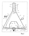
- FIG. 2 shows a schematic axial section through a phase contrast x-ray tomography device
- FIG. 3 shows an axial half-section through a modified phase contrast x-ray tomography device, which has a plurality of electron guns and is suitable for long objects;
- FIG. 4 shows an axial plan view of beam boundaries and x-ray gratings of a phase contrast x-ray tomography device, with some elements folded over into the plane of the drawing (upper section of the figure), and a lateral view of the tomography device (lower part of the figure);
- FIG. 5 shows an axial partial section through target ring and diffraction grating of a further phase contrast x-ray tomography device
- FIG. 6 shows an enlarged view of the target ring according to FIG. 5 ;
- FIGS. 7 to 11 show various interference patterns which result for different grating constants of the x-ray gratings and different tilting of the same relative to one another;
- FIG. 12 shows a perspective view of a first rotationally symmetrical x-ray grating structure
- FIG. 13 shows a perspective view of a segment of a polygonal x-ray grating structure
- FIG. 14 shows a perspective view of a further polygonal x-ray grating structure
- FIG. 15 shows a segment of a further rotationally symmetrical x-ray grating structure
- FIG. 16 shows a perspective view of a further rotationally symmetrical x-ray grating structure, which is composed of arc-shaped segments;
- FIG. 17 shows a similar view to FIG. 15 , in which however the transmission regions of the grating structure are arranged along slightly inclined helical lines;
- FIG. 18 shows a perspective view of a macroscopically cylindrical x-ray grating structure with helically running rules
- FIG. 19 shows a similar view to FIG. 18 , in which however the segments of the x-ray grating structure are rectilinear;
- FIG. 20 shows a perspective view of polygonal x-ray grating structure as illustrated in FIG. 19 , but with this one being additionally surrounded by a polygonal partially multi-row detector structure;
- FIG. 21 shows the block diagram of an evaluation device of the x-ray tomography device
- FIG. 22 shows an illustration of an x-ray tomography device which allows an exact radial irradiation and in which the target structure and the first x-ray-light diffraction structure are combined in one component, a rotating screen device being additionally provided;
- FIG. 23 shows a schematic view of a width-adjustable rotating screen for lateral limitation of an x-ray beam in an examination plane
- FIG. 24 shows an illustration of an x-ray tomography device with the x-ray beam passing through the outlet window twice and additionally passing through the target and the housing wall, thus likewise allowing an exact radial irradiation
- FIG. 25 shows an illustration of a screen which limits the rotating x-ray fan in its height through a wobbling motion and thus reduces the irradiation dose
- FIG. 26 shows an axial section through a phase contrast x-ray tomography device having a grating which surrounds the examination region and at the same time performs the function of a coherence grating and of a phase grating.
- FIG. 1 shows the basic structure of a phase contrast x-ray tomography device.
- An x-ray source 10 which provides x-ray light of different wavelength which is not coherent, is also shown in FIG. 1 .
- a coherence grating 12 Arranged behind the x-ray source 10 is a coherence grating 12 , which removes quasi-coherent x-ray light from the light of the x-ray source 10 .
- Such a coherence grating 12 is not necessary if the x-ray source 10 has a very small emission point, adapted to the Talbot condition, or a corresponding stripe structure ao.
- An examination region 14 is bounded by a square represented by dashes.
- phase grating 16 Situated behind the examination region 14 is a phase grating 16 , and at the Talbot distance from the latter there is provided an amplitude grating 18 . All the aforementioned gratings are structures which are effective for x-rays and satisfy the Talbot condition.
- a ring-shaped detector strip 20 Arranged behind the amplitude grating 18 is a ring-shaped detector strip 20 , also referred to hereinbelow as the detector strip 20 , the longitudinal direction of which coincides with the main extension direction of the amplitude grating 18 .
- the individual rules are to be envisaged as being perpendicular to the drawing plane, following one another at a small spacing a 1 , a 2 .
- Typical rule spacings a 1 , a 2 are less than 10 ⁇ m, preferably in the range from about 1 to about 3 ⁇ m.
- FIG. 1 An arrangement as shown in FIG. 1 produces in the plane of the detector strip 20 an interference pattern with light and dark stripe sections.
- the interference pattern obtained with an empty examination region 14 is to be understood as a reference interference pattern for the empty examination region 14 .
- the interference pattern changes.
- the differences in the light and dark stripe can be converted into electrical signals by the detector strip 20 , and these signals can then be converted into a phase image.
- the edge contour of the phase object 22 is indicated by dashes in FIG. 1 in a manner tilted into the drawing plane.
- the interference pattern IF too is rotated into the drawing plane for illustration purposes.
- the interference pattern shown is obtained by a plate with trapezoidal cross-section, as shown in FIG. 1 .
- the phase object 22 which is transparent to x-rays per se can now be recognized.
- the interference pattern which are found in the vicinity of the phase image pass right through also in that region in which the image of the phase object 22 was previously situated.
- FIG. 2 shows a tomography device with a circulating x-ray emission point F.
- a target ring 58 has the shape of a truncated cone with the vertex facing downwards and lying on the device axis.
- the x-ray tomography device has a gas-tight evacuated housing 24 , also referred to hereinbelow as the housing 24 , which includes a housing neck 26 , an outer conical housing wall 28 , i.e., the housing wall 28 , an obliquely downwardly and inwardly sloping bottom wall 30 , i.e., the bottom wall, a cylindrical housing wall 38 , i.e., the housing wall 38 running axially back again, an upwardly converging truncated-cone shaped housing wall 40 , i.e., the housing wall 40 adjoining the latter, and an end wall 42 .
- a gas-tight evacuated housing 24 also referred to hereinbelow as the housing 24 , which includes a housing neck 26 , an outer conical housing wall 28 , i.e., the housing wall 28 , an obliquely downwardly and inwardly sloping bottom wall 30 , i.e., the bottom wall, a
- the entire inner space of the housing 24 is evacuated to a pressure of less than 10 ⁇ 5 mbar. This vacuum can be produced both by hermetic tightness and by specific pumping with a mounted-on vacuum pump 25 during operation.
- an electron gun 44 Situated inside the housing 24 is an electron gun 44 .
- the latter includes, schematically represented, a heated cathode 46 , a control electrode 48 , an accelerating electrode 50 , an electrostatic lens 52 and a deflecting coil 54 .
- an electrostatic deflecting unit which comprises a deflecting plate capacitor may also be used.
- An electron beam 56 is represented in dashes by its centre line and its envelopes.
- a ring-shaped target 58 Arranged on the bottom wall 30 is a ring-shaped target 58 , also referred to hereinbelow as the target 58 , which can be made from material which is customary for x-ray targets.
- the target 58 has the shape of a widely opened truncated cone with an opening angle of the cone vertex of about 160°.
- x-ray window 63 Situated at the junction between the bottom wall 30 and the cylindrical housing wall 38 is a small gap 60 which is closed by an x-ray window 63 .
- the latter extends over a full 360°, so that x-ray light 62 which is formed on impingement of the electron beam 56 on the target 58 can emerge, in any angular position, produced by the deflecting coil 54 or a deflecting capacitor, of the focal point F relative to the axis of the housing 24 , through a corresponding region of the x-ray window 63 .
- the x-ray light 62 is depicted only in its usable fan shaped region which is predetermined by the height of the x-ray window 63 .
- further x-ray light also radiates into the upper half-space, but this light is absorbed by the housing wall 28 , bottom wall 30 , cylindrical housing wall 38 , housing wall 40 , and end wall 42 of the housing 24 and not used for measurement purposes.
- the housing 24 may optionally be surrounded with additional shielding material.
- the x-ray window 63 may, at the same time, be chosen from a material which absorbs undesired parts of the x-ray spectrum. These are in particular long-wave portions of the continuous portion of the spectrum.
- a ring-shaped phase grating 64 also referred to hereinbelow as the phase grating 64
- a likewise ring-shaped amplitude grating 66 i.e., the amplitude grating 66 , satisfies the Talbot condition.
- the x-ray fan used for measurement purposes is directed obliquely downwards and can, on the opposite side of the bottom wall 30 located on the right in FIG. 2 , pass through under this wall.
- the bottom wall 30 can have a lower turned-up circumferential wall at its radially inner end.
- a ring-shaped phase grating 64 which is indicated by dashes.
- a ring-shaped amplitude grating 66 Radially outside the phase grating 64 there is situated coaxially a likewise ring-shaped amplitude grating 66 .
- a ring-shaped detector strip 68 also referred to hereinbelow as the detector strip 68 .
- the ring shaped detector strip 68 comprises in the strip longitudinal direction detector elements following one another at a very small spacing, the spacing of which is smaller than the period of interference patterns which are produced by the phase grating 64 and the amplitude grating 66 in the region of the detector strip 68 .
- the detector strip 68 comprises a smaller number (e.g. 8, 16 or 32) of detector elements following one another at an equal small spacing.
- the detector strip 68 thus forms as a whole a ring-shaped detector area with a plurality of 100,000s of detector pixels in a ring row, which may comprise for example about 250,000 detector elements following one another in the circumferential direction (for a whole-body phase contrast tomography device of about 80 cm clear width), if one detector element is provided for each rule of the x-ray gratings. 8, 16 or 32 of such lines of detector elements are stacked axially one after the other at the spacing of the detector elements. How many rows are provided one after the other in the axial direction is a question of the optimization of the detectors.
- one detector ring row is sufficient. If detectors with pixel sizes of a fraction of the desired spatial resolution are available, the phase measurement can be extended to a plurality of pixels, e.g. 3 ⁇ 3 or 4 ⁇ 4 pixels per resolution point. If the geometrical resolution of the entire arrangement is limited by other factors anyway (e.g. focal spot size and magnification), a 3- to 4-row detector per resolution row is recommended. A further increase in the number of rows is expedient on account of better utilisation of the x-ray radiation, but is only possible if the grating lamellae, with increasing axial distance from the path plane of the focal point F, are correspondingly inclined, which in turn increases the outlay on the grating arrangement.
- the phase measurement of the wavefront has to be made possible by displacing one of those structures responsible for producing the interference image (x-ray source 10 , coherence grating 12 , phase grating 16 , amplitude grating 18 ) by very small distances amounting to fractions of the spacing of two grating lines, in order to obtain, when small displacements of a diffraction-relevant components are known, additional information about the intensity profile, whereupon these additional measuring points can be used as additional sampling points for adapting a sine curve and for determining the phase position of this sine curve.
- the division of the detector strip 68 is sufficiently small to be able, without the above-mentioned relative movements by very small distances, to measure the interference pattern sufficiently precisely to determine the phase position of the wavefront therefrom.
- the x-ray grating i.e. the phase grating 64 and the amplitude grating 66 , are shown in the drawing as gratings which have layers, made from x-ray-transparent material and x-ray-absorbing material, following one another alternately in the direction of the device axis (or even oriented in the direction of the opposite emission point path in the case of particularly wide strips).
- the two x-ray gratings together produce an interference image.
- Such an interference image can also be obtained with x-ray gratings in which the layers made from transparent material and absorbing material following one another alternately are stacked periodically one after the other in the circumferential direction.
- the x-ray light 62 has the shape of a very slightly diverging, very flat, fan-shaped x-ray beam.
- the fan-shaped x-ray light 62 is distinguished with regard to its course and its geometry by the following angles: An angle E, at which its plane of rotation is inclined relative to a plane which is situated transversely to the device axis. Furthermore, an elevation fan angle we, which represents the spread angle of the fan in an axial sectional plane. Furthermore, a spread angle of the fan in the circumferential direction wu, which represents the spread angle of the fan in the plane of rotation. These different angles are marked in FIGS. 2 to 4 . In the other figures they are only partially marked. In the vicinity of the axis of the housing 24 there is shown in each case an examination object 70 , also referred to hereinbelow as the object 70 , (by way of example in the form of a light bulb) with its preferred movement direction 72 .
- the x-ray light 62 passes through the examination object 70 , with the latter in a preset position, in exactly one sectional plane per detector resolution row.
- the latter can be moved preferably in the axial direction by a schematically indicated drive 72 .
- x-ray tomography device can be moved.
- the electron beam 56 can be moved on a circular path about the axis of the housing 24 , as indicated in the drawing by an arrow 74 .
- the point of impingement F of the electron beam 56 on the target 58 then travels onto a circle which is concentric with respect to the housing axis, and the x-ray light 62 then emerges at an appropriate angular orientation from the x-ray window 63 .
- FIG. 3 shows a modified tomography device.
- Components which functionally correspond to components already described with reference to FIG. 2 are provided with the same reference symbols and do not need to be described again in detail.
- a plurality of electron guns 44 which have a similar structure to the electron gun shown in FIG. 2 .
- the electron guns 44 according to FIG. 3 are, however, now distributed at a regular spacing over the circumferential extent of the housing 24 , so that the electron beams 56 generated respectively by them have only to sweep over a partial region of the circumferential extent of the ring-shaped target 58 .
- Through sequential triggering of the different electron guns 44 altogether the entire circumferential extent of the target 58 is then covered, it also being possible to use a plurality of electron guns simultaneously, provided that their x-ray beam fans do not overlap on the detectors.
- the different electron guns do not need to be activated successively in the circumferential direction.
- the electron guns may also be activated in a different order, which may be advantageous as regards heat problems in the target 58 . It is advantageous but not absolutely essential, merely, for all the electron guns 44 to have been activated exactly once in this way in a preset period of time (scanning cycle) and for their electron beam 56 to have been moved on the assigned arc-shaped segment of the entire circumferential extent of the target 58 .
- FIG. 4 shows a plan view of the bottom section of the tomography device, with the angular extent of the x-ray fan in the direction perpendicular to the device axis (examination plane) and the fanning of the x-ray light in the vertical direction (elevation fanning) being shown in more detail. Furthermore, in the drawing a few rules are indicated in the detail representation for the phase grating 64 and the amplitude grating 66 . The structure of these ring-shaped x-ray gratings will be explained in more detail later with reference to FIGS. 14 and 22 .
- the point of impingement of the electron beam 68 on the target 58 is denoted by F in FIG. 4 .
- K stands for the track on which the focal spot F of the electron beam moves over the target 58 .
- a segmented screen configured as a screen grating is denoted by 133 in FIG. 4 . It comprises a large number of screen bars 132 which follow one another at a small spacing in the circumferential direction and between which screen windows 134 remain.
- the screen 133 is arranged in a spatially fixed manner at a small spacing on the inner or outer side of the x-ray window 63 and the electron beam 56 is displaced, by suitable excitation of the deflecting coil 54 , in increments on the target 58 in such a manner that the focus F is in each case radially aligned with the centre of one of the screen windows 134 .
- a specific eccentric position of the examination volume can be achieved too by angle of rotation-dependent displacement of the electron beam point of impingement F relative to the centre of the screen window 134 .
- the evaluation of the output signals of the detector strip 68 is performed, when using the screen bodies according to FIG. 3 and according to FIG. 4 , such that in each case a partial region of the detector strip 68 on which usable interference patterns are obtained is activated or its output signal evaluated.
- the selection of this region may also be performed with evaluation of the deflecting signals for the deflecting coil 54 .
- the dose for the patient is reduced, and in particular in an embodiment according to FIG. 3 the image acquisition speed is increased.
- FIGS. 5 and 6 show again schematically the beam path between the ring-shaped gap 60 and the detector strip 68 on an axially enlarged scale.
- the inclination of the target 58 results in a reduction of the seen size of the punctiform x-ray light source formed by the focus F of the electron beam 56 on the target 58 . If the cross-section of the incident electron beam 56 has the size D, only a fraction d of this size appears when seen in the axial direction.
- FIG. 7 shows schematically an interference pattern as obtained in the light-sensitive area of the detector strip 68 for a preset relative position of phase grating 64 and amplitude grating 66 .
- Relative position is to be understood here as both the distance perpendicularly to the grating surface and the inclination of the grating lines of the two gratings with respect to one another.
- the interference pattern comprises horizontal stripes H lying equally spaced one beside the other.
- a second group of stripes running at a small angle inclined to the stripe H is denoted by N.
- the stripes H and N in FIG. 7 form, when seen additively placed one above the other, regions with a large black portion and regions of high brightness, which roughly speaking each have a lozenge-like structure.
- the brightness profile from left to right corresponds to a sinusoidal profile with a fundamental value, since no negative brightness can occur.
- the amplitude and phase position in these six detector elements can now be calculated by mathematical methods (fitting, Fourier transformation).
- FIG. 8 shows a similar image, in which however the phase position between the interferences, which are obtained by phase grating and amplitude grating, is changed.
- a change of the phase position can be obtained by a displacement of the object and/or a displacement of the x-ray light source and/or a displacement of the phase grating and/or a displacement of the amplitude grating and/or by a tilting of the phase grating and/or a tilting of the amplitude grating.
- the changed interference pattern also results in a changed brightness distribution in the brightness profile shown below the interference pattern, to be precise in the form that the sinusoidal brightness distribution has shifted by one detector pixel to the right.
- FIG. 9 shows a modified geometry, in which the phase grating and the amplitude grating are tilted by opposite and equal angles relative to a reference direction.
- This arrangement would likewise be suitable for an elongated resolution pixel, since the upper and lower pixel row is identical to the middle row and the phase position of the sinusoidal oscillation can be actually determined from only three sampling points.
- FIGS. 7 and 8 a sinusoidal intensity distribution results, from which the phase position and amplitude can be determined as in FIGS. 7 and 8 . It can be seen that by tilting the gratings an interference pattern which has a smaller period length in the horizontal direction is obtained. The period length is therefore adjustable by the tilting angle w.
- FIG. 11 shows a stripe pattern which is obtained by choosing slightly different grating constants for phase grating and amplitude grating. Otherwise, the arrangement of the gratings corresponds to that according to FIG. 9 .
- the stripe pattern is “sheared” in the horizontal direction, and it can thus be evaluated equivalently to the stripe pattern in FIG. 10 .
- the tilting angles of the gratings and the grating constants it is thus possible to adjust the interference pattern of each resolution pixel such that in each associated detector pixel array of almost any desired choice (e.g. 3 ⁇ 4), a sinusoidal oscillation can be readily adapted with all associated detector pixels.
- grating constants it is even possible to arrange one of the gratings absolutely horizontally without disadvantages, as shown in FIGS. 12 to 16 .
- a ring-shaped x-ray grating 76 also referred to hereinbelow as the x-ray grating 76 . It consists of an axial succession of layers 78 , 80 , which consist of different material. The difference in the materials may lie in the velocity of propagation of x-ray light, and then the x-ray grating 76 is a phase grating. The difference in the layers 78 , 80 may, however, also lie in the absorption of x-ray light, and then the x-ray grating 76 is an amplitude grating.
- x-ray gratings are produced such that there is a basic structure which is transparent to x-ray light and is provided with a fine groove pattern. This basic structure is then thinly coated with another material. At the groove base, which is situated perpendicular to the direction of propagation of the x-ray light, this thin material influences the x-ray light only slightly, since the layer there is very thin. By contrast, in the regions of the groove walls, the x-ray light has to pass through the vapour-deposited material over a long way, so that there is a great influence.
- the x-ray grating thus has wide regions in which the light is only influenced a little in terms of phase and in terms of amplitude, and narrow regions which greatly shade the light, or cause a large phase change.
- the ring-shaped x-ray grating 76 according to FIG. 12 is macroscopically in one piece.
- Such ring-shaped x-ray gratings may, however, also be composed of a plurality of segments.
- FIG. 13 shows a first such bar-shaped ring segment 82 , also referred to hereinbelow as the segment or segments 82 , having end faces beveled at 30°.
- Such bar-shaped ring segments 82 can be assembled to form a hexagonal ring, so that an x-ray grating 76 as shown in FIG. 14 is obtained.
- a ring-shaped x-ray grating 76 shown in FIG. 16 can be assembled.
- a ring segment 82 as shown in FIG. 17 can be produced.
- the grating lines are inclined obliquely to the ring axis.
- a ring-shaped x-ray grating 76 as shown in FIG. 18 can then be produced. It can be seen that the layers 78 , 80 form a multi-start helix.
- the outer end faces can be used as adjusting and fitting surfaces which cooperate with shoulders running transversely to the device axis. It is thus not necessary to form seating surfaces of the housing at a preset small angle to the device axis in order to tilt grating lines in this way. Nor is there any need to provide adjusting means to adjust the inclination of the grating lines.
- FIG. 19 shows a similar x-ray grating 76 to FIG. 18 , but which is configured as a hexagonal ring.
- FIG. 20 shows an inner phase x-ray grating 64 and a ring-shaped amplitude x-ray grating 66 surrounding the latter at a spacing, the gratings both being configured similar to the x-ray grating 76 but having twelve segments correspondingly bevelled at the circumferential ends. In this way, x-ray gratings and detector rows or strips having a large diameter can be assembled from smaller units.
- the detector strip 68 which is likewise constructed from straight detector segments 84 , the ends of which are bevelled at 15°. It has detector element rows 68 - 1 , 68 - 2 , . . . 68 - i, . . . .
- FIG. 20 It is easily conceivable in FIG. 20 now to combine 3- or higher-row detector strips, a grating ring according to FIG. 19 and a grating ring according to FIG. 14 and to apply the evaluation method according to FIG. 10 .
- Higher-row detector strips with pixels 68 ( 1 / 1 ), . . . , 68 ( i/j ) are perfectly appropriate here and can be used to provide several layers of the tomogram simultaneously.
- commercially available strip detectors even in the smaller dimension generally have 64 and more rows and an extent of more than 6 mm. With resolution pixels of for example 300 ⁇ m these are already 20 simultaneously measured layers.
- a production in a width of 6 mm is far more economical than with a width of 0.3 mm. The assembly of the grating strips is thus also simplified.
- x-ray gratings and detector rows having a large diameter can be assembled from smaller units.
- FIG. 21 schematically illustrates an evaluating unit 86 which converts the output signals of the detector strip 68 into a phase image of the object 70 .
- the evaluating unit 86 has a programmable processor 87 which cooperates with a position sensor 88 which provides a signal corresponding to the position of the electron beam 56 in the circumferential direction. This signal can, for example, be derived from the activation signal of the deflecting coil 54 . This signal is then at the same time information about how the fan-shaped x-ray light 62 is angularly oriented in the examination plane.
- the programmable processor 87 then has a subunit 90 which is supplied with the output signals of the detector strip 68 and stores these.
- the subunit 90 can directly match a sinusoidal intensity profile to the output signals of neighbouring detector elements, e.g. by least square fit or Fourier transformation. This intensity profile is compared with a reference intensity profile which had been obtained without an object and is stored in a reference profile memory 91 . By comparison, the phase shift due to the object is then calculated.
- the mean absorption value of the object and the amplitude of the sinusoid-like pixel information are available, as in other phase contrast methods, likewise as imaging information and can also be utilised in the further processing units.
- phase shifts for the different image pixels are then stored in a memory 92 , in memory areas 92 - 1 , 92 - 2 , . . . 92 - i , . . . corresponding to the layers of the object, in which the phase shifts calculated pixelwise represent an initially numeric image of the object.
- the determination of the phase position changed by the object is carried out successively by slightly changing test conditions which affect the formation of the interference patterns. Suitable changes are primarily changes in the position of the focal spot F of the electron beam 56 , changes in the position of phase grating 64 and amplitude grating 66 .
- the means in one example can include microactuators 146 , e.g. piezoelectric actuators, as indicated in FIG. 20 acting in a translatory manner on the phase x-ray grating 64 .
- the means for changing one or more relative positions can include a linear drive, a rotary drive, or a tilting device.
- the means can include the aforementioned microactuator, such as a piezoactuator, i.e., a piezoelectric actuator, a magnetorestrivtive actuator, or an electret actuator.
- the interference figure is then measured again for different positions of the movable components.
- the different output signals of the detector elements 68 - i which are determined for different relative positions k are stored in memory fields of the memory 90 .
- phase image of the object can then be created again.
- reference interference image of the tomography device alone (without an object; reference image) is a device constant which only needs to be re-determined at longer intervals, in order to eliminate ageing effects and possibly also thermal instabilities.
- reference interference pattern also has to be re-determined when the geometry of the arrangement changes for special examinations.
- phase contrast tomography device has no components which are to be machined to high accuracy, except for the x-ray gratings and the detector strip. It is only necessary to move the object mechanically in the phase contrast tomography device if the imaging volume is to be greater than the grating structure comprising 20 layers.
- FIG. 22 illustrates a modified tomography device, in which the x-ray diffraction structure 64 and the target ring 58 are combined into one component.
- the lamellae of the x-ray diffraction structure 64 are arranged at a grating spacing a 1 and preferably consist, just as the target 58 , of a material of high density and high atomic number, so that the surface of the diffraction structure is in principle well suited for generating x-rays.
- interspaces between the grating lamellae are filled with a material 67 which is of good thermal conductivity and low radiation absorption, and which may at the same time have an x-ray filter effect.
- the structuring required for the coherence of the source point is produced by the projecting groups of lamellae illustrated in the combined unit 65 , which are arranged at a spacing a 0 .
- the electron beam impinging obliquely from above is shaded in the intermediate regions, so that no more x-ray radiation is generated there.
- the intensity of the electron beam 56 is better utilised.
- the irradiation of the object can take place in an exact plane, in contrast to the variants according to FIGS. 2 to 6 .
- FIGS. 22 and 23 a rotating screen device denoted as a whole by 100 is illustrated in FIGS. 22 and 23 , which device is not necessary for the functioning of the tomography device in the case of technical objects, but is useful for reducing the radiation exposure for patients in medical applications. It comprises components 100 to 131 .
- the x-ray beam fan 62 is limited to the required limit of the angle wu and we by x-ray windows 116 , 118 adjustable relative to one another.
- a bearing 104 of the rotating screen is realised by a large-diameter ball bearing at the bottom 30 of the housing 24 , but an air cushion bearing or a magnetic bearing would also be usable here.
- a drive 110 and a position indication 131 ensure the desired dynamic positioning with respect to the x-ray emission point F.
- the screen 102 consists of two cylindrical screen parts 112 , 114 which, except for windows 116 to 119 transparent to x-ray light, are non-transparent to x-ray light.
- the windows 116 and 118 thus together define a gap S, which is adjustable by rotation of one of the screen parts 112 , 114 on the other, the x-ray beam fan, emerging in the direction of the object, in the circumferential direction.
- the screen parts 112 , 114 can be adjusted, for example, by manual adjustment of an elongated-hole connection in the circumferential direction relative to one another, in order to change the width of the gap S.
- the two screen parts 112 , 114 can also be coupled via an actuator 120 acting in the circumferential direction, which acts on arms 122 , 124 attached to the screen part 112 and 114 , respectively.
- Balancing bodies 126 and 128 which are arranged symmetrically in each case on both sides of the windows 116 , 118 , serve for mass balancing for the lighter windows 116 , 118 .
- a further balancing body 130 is arranged, diametrically opposite the adjusting device 120 , 122 , 124 , on the inner screen part 112 and balances out the unbalance produced by the adjusting device.
- the actuator 120 is wirelessly supplied with energy and remotely controlled wirelessly (optionally via the same transmission route).
- the transverse dimension of the x-ray light 62 in the examination plane can be preset via the gap S.
- FIG. 24 illustrates a further variant, with which an irradiation of the object can likewise be carried out in an exact plane.
- the target ring 58 and the housing bottom 30 is dimensioned such that the x-ray fan can radiate through the latter on the opposite side.
- FIG. 24 illustrates additionally a modification of the rotating screen with a suspension 109 in the form of a bell or spoked crown, the bearing 104 of which is fastened to a central axle 108 which is fastened to the end wall 42 of the housing 24 .
- a co-rotating shielding body 61 which limits the radiation emission into the detector regions adjacent to the emission point F.
- the evaluation of the output signals of the detector row 68 is carried out using the screen bodies according to FIG. 22 to FIG. 24 such that in each case a partial region of the detector row 68 on which usable interference patterns are obtained is activated and its output signals are evaluated.
- the selection of this region is carried out using the position indicator 131 or by evaluation of the deflecting signals for the deflecting coil 54 .
- FIG. 25 shows a screen 150 which limits the spread angle of the x-ray fan in the elevation direction (spread angle in the axial sectional plane).
- An upper screen ring 152 and a lower screen ring 154 are fastened to a suitable place of the housing 24 via in each case at least three actuators (lifting magnets, vibrating magnets, piezo-positioners, pneumatic cylinders, magnetostrictive actuators) 156 , with optionally also one of the two screen rings 152 , 154 being stationarily mountable.
- actuators lifting magnets, vibrating magnets, piezo-positioners, pneumatic cylinders, magnetostrictive actuators
- the corresponding screen can now execute a wobbling motion, whereby the elevation angle we of the x-ray fan 62 is locally limited and at the same time it is ensured that the radiation in the x-ray fan 62 which penetrates the patient can also be registered on the detector. This makes it possible to reduce the radiation exposure for the patient.
- FIG. 26 shows a phase contrast x-ray tomography device according to a further exemplary embodiment of the invention.
- the bottom wall 30 of the evacuated housing 24 on which the truncated-cone-shaped target 58 is arranged, and also the target 58 itself, are formed from a material transparent to the x-ray light.
- the opening angle of the truncated-cone-shaped target 58 is furthermore chosen such that the x-ray light, after it has emerged from the outlet window 63 and passed through the examination region, impinges on the outlet window 63 again on the diametrically opposite side.
- a grating 200 Arranged radially inside when seen from the outlet window 63 is a grating 200 which surrounds the examination region and simultaneously performs the function of the coherence grating 12 and of the phase grating 64 .
- a grating 200 Arranged radially outside the bottom wall 30 are the amplitude grating 66 and the detector strip 20 , the functioning of which is unchanged compared with the previous exemplary embodiments.
- phase contrast x-ray tomography device functions as follows:
- the x-ray light generated at the focal spot F on the target 58 after it has emerged from the outlet window 63 , impinges firstly on the grating 200 , whereby x-ray light is generated with sufficient coherence for the phase measurement.
- the x-ray light After passing through the examination region, the x-ray light impinges on the grating 200 again and passes through the latter in the opposite direction.
- the grating 200 serves now, as part of the phase measuring device together with the amplitude grating 66 and the detector strip 20 , to detect the phase position of the x-ray light.
- the x-ray light enters the housing 24 again via the outlet window 63 , in order thereupon to pass through the target 58 and the bottom wall 30 . There, it finally impinges on the amplitude grating 66 and the detector strip 20 .
- the exemplary embodiment just described thus makes it possible with only two gratings to realise a phase contrast tomography device which does not require any parts moving around the object to be examined in order to detect the individual tomography projections. If a detector strip 20 with a sufficiently high resolution (for example with the resolution of the amplitude grating 66 ) were used, the amplitude grating 66 could moreover be dispensed with.
- phase contrast x-ray tomography device In combination with the exemplary embodiment according to FIG. 22 , a phase contrast x-ray tomography device would even be conceivable, in which only a target provided with a grating structure and a high-resolution detector are used.
Landscapes
- Health & Medical Sciences (AREA)
- Life Sciences & Earth Sciences (AREA)
- Engineering & Computer Science (AREA)
- Medical Informatics (AREA)
- Physics & Mathematics (AREA)
- General Health & Medical Sciences (AREA)
- Pathology (AREA)
- High Energy & Nuclear Physics (AREA)
- Radiology & Medical Imaging (AREA)
- Nuclear Medicine, Radiotherapy & Molecular Imaging (AREA)
- Surgery (AREA)
- Biophysics (AREA)
- Biomedical Technology (AREA)
- Heart & Thoracic Surgery (AREA)
- Molecular Biology (AREA)
- Optics & Photonics (AREA)
- Animal Behavior & Ethology (AREA)
- Public Health (AREA)
- Veterinary Medicine (AREA)
- Theoretical Computer Science (AREA)
- Pulmonology (AREA)
- Chemical & Material Sciences (AREA)
- Biochemistry (AREA)
- Analytical Chemistry (AREA)
- General Physics & Mathematics (AREA)
- Immunology (AREA)
- Toxicology (AREA)
- Spectroscopy & Molecular Physics (AREA)
- General Engineering & Computer Science (AREA)
- Crystallography & Structural Chemistry (AREA)
- Mathematical Physics (AREA)
- Analysing Materials By The Use Of Radiation (AREA)
- Apparatus For Radiation Diagnosis (AREA)
Applications Claiming Priority (4)
| Application Number | Priority Date | Filing Date | Title |
|---|---|---|---|
| DE102012005767.9 | 2012-03-25 | ||
| DE102012005767 | 2012-03-25 | ||
| DE102012005767A DE102012005767A1 (de) | 2012-03-25 | 2012-03-25 | Phasenkontrast-Röntgen-Tomographiegerät |
| PCT/EP2013/000873 WO2013143672A1 (de) | 2012-03-25 | 2013-03-22 | Phasenkontrast-röntgen-tomographiegerät |
Publications (2)
| Publication Number | Publication Date |
|---|---|
| US20150279496A1 US20150279496A1 (en) | 2015-10-01 |
| US10076297B2 true US10076297B2 (en) | 2018-09-18 |
Family
ID=48095778
Family Applications (1)
| Application Number | Title | Priority Date | Filing Date |
|---|---|---|---|
| US14/387,786 Active 2034-07-09 US10076297B2 (en) | 2012-03-25 | 2013-03-22 | Phase contrast X-ray tomography device |
Country Status (4)
| Country | Link |
|---|---|
| US (1) | US10076297B2 (de) |
| EP (1) | EP2830504B1 (de) |
| DE (2) | DE102012005767A1 (de) |
| WO (1) | WO2013143672A1 (de) |
Cited By (25)
| Publication number | Priority date | Publication date | Assignee | Title |
|---|---|---|---|---|
| US10349908B2 (en) * | 2013-10-31 | 2019-07-16 | Sigray, Inc. | X-ray interferometric imaging system |
| US10658145B2 (en) | 2018-07-26 | 2020-05-19 | Sigray, Inc. | High brightness x-ray reflection source |
| US10656105B2 (en) | 2018-08-06 | 2020-05-19 | Sigray, Inc. | Talbot-lau x-ray source and interferometric system |
| US20200319120A1 (en) * | 2017-12-04 | 2020-10-08 | Konica Minolta, Inc. | X-ray imaging system containing x-ray apparatus having gratings and object housing for setting environmental condition independent of external environment |
| US10845491B2 (en) | 2018-06-04 | 2020-11-24 | Sigray, Inc. | Energy-resolving x-ray detection system |
| US10962491B2 (en) | 2018-09-04 | 2021-03-30 | Sigray, Inc. | System and method for x-ray fluorescence with filtering |
| US10976273B2 (en) | 2013-09-19 | 2021-04-13 | Sigray, Inc. | X-ray spectrometer system |
| USRE48612E1 (en) | 2013-10-31 | 2021-06-29 | Sigray, Inc. | X-ray interferometric imaging system |
| US11056308B2 (en) | 2018-09-07 | 2021-07-06 | Sigray, Inc. | System and method for depth-selectable x-ray analysis |
| US11143605B2 (en) | 2019-09-03 | 2021-10-12 | Sigray, Inc. | System and method for computed laminography x-ray fluorescence imaging |
| US11175243B1 (en) | 2020-02-06 | 2021-11-16 | Sigray, Inc. | X-ray dark-field in-line inspection for semiconductor samples |
| US11215572B2 (en) | 2020-05-18 | 2022-01-04 | Sigray, Inc. | System and method for x-ray absorption spectroscopy using a crystal analyzer and a plurality of detector elements |
| US11282668B2 (en) * | 2016-03-31 | 2022-03-22 | Nano-X Imaging Ltd. | X-ray tube and a controller thereof |
| US11549895B2 (en) | 2020-09-17 | 2023-01-10 | Sigray, Inc. | System and method using x-rays for depth-resolving metrology and analysis |
| US11686692B2 (en) | 2020-12-07 | 2023-06-27 | Sigray, Inc. | High throughput 3D x-ray imaging system using a transmission x-ray source |
| US11885755B2 (en) | 2022-05-02 | 2024-01-30 | Sigray, Inc. | X-ray sequential array wavelength dispersive spectrometer |
| US11992350B2 (en) | 2022-03-15 | 2024-05-28 | Sigray, Inc. | System and method for compact laminography utilizing microfocus transmission x-ray source and variable magnification x-ray detector |
| US12181423B1 (en) | 2023-09-07 | 2024-12-31 | Sigray, Inc. | Secondary image removal using high resolution x-ray transmission sources |
| US12209977B2 (en) | 2023-02-16 | 2025-01-28 | Sigray, Inc. | X-ray detector system with at least two stacked flat Bragg diffractors |
| US12360067B2 (en) | 2022-03-02 | 2025-07-15 | Sigray, Inc. | X-ray fluorescence system and x-ray source with electrically insulative target material |
| US12429436B2 (en) | 2024-01-08 | 2025-09-30 | Sigray, Inc. | X-ray analysis system with focused x-ray beam and non-x-ray microscope |
| US12429437B2 (en) | 2023-11-07 | 2025-09-30 | Sigray, Inc. | System and method for x-ray absorption spectroscopy using spectral information from two orthogonal planes |
| US12431256B2 (en) | 2024-02-15 | 2025-09-30 | Sigray, Inc. | System and method for generating a focused x-ray beam |
| US12480892B2 (en) | 2020-12-07 | 2025-11-25 | Sigray, Inc. | High throughput 3D x-ray imaging system using a transmission x-ray source |
| US12510677B2 (en) | 2024-01-18 | 2025-12-30 | Sigray, Inc. | Sequential array of x-ray imaging detectors |
Families Citing this family (12)
| Publication number | Priority date | Publication date | Assignee | Title |
|---|---|---|---|---|
| US9801600B2 (en) * | 2014-11-17 | 2017-10-31 | Rensselaer Polytechnic Institute | X-ray phase-contrast imaging |
| DE102017103332A1 (de) * | 2017-02-17 | 2018-08-23 | Thyssenkrupp Ag | Magnetlager und Verfahren zum Betrieb eines Magnetlagers |
| CN106963405B (zh) * | 2017-03-22 | 2023-04-07 | 浙江大学 | 一种新型口腔锥束ct |
| EP3608659B1 (de) * | 2017-04-07 | 2025-04-02 | Konica Minolta, Inc. | Qualitätskontrollverfahren |
| US10463332B2 (en) * | 2018-02-02 | 2019-11-05 | Siemens Healthcare Gmbh | Spectral topogram-based determination of imaging parameters |
| JP6881682B2 (ja) * | 2018-05-16 | 2021-06-02 | 株式会社島津製作所 | X線イメージング装置 |
| WO2019239624A1 (ja) * | 2018-06-15 | 2019-12-19 | 株式会社島津製作所 | X線イメージング装置 |
| US10799193B2 (en) | 2019-02-12 | 2020-10-13 | Malcova LLC | Method and apparatus for anatomically-specified conformation computed tomography |
| US10531844B1 (en) * | 2019-08-09 | 2020-01-14 | Malcova LLC | Narrow beam CT using a 3D fluence modulation and scatter shield system |
| EP3889973A1 (de) * | 2020-04-01 | 2021-10-06 | Koninklijke Philips N.V. | Fokussierte gittervorrichtungen mit grossem aspektverhältnis |
| US11622735B1 (en) | 2022-10-20 | 2023-04-11 | MALCOVA, Inc. | Plural-plane narrow-beam computed tomography |
| US12181424B1 (en) | 2024-07-24 | 2024-12-31 | MALCOVA, Inc. | Method and apparatus of stationary-source nonplanar-trajectory narrow-beam computed tomography |
Citations (100)
| Publication number | Priority date | Publication date | Assignee | Title |
|---|---|---|---|---|
| US4075489A (en) * | 1977-01-21 | 1978-02-21 | Simulation Physics | Method and apparatus involving the generation of x-rays |
| US4122346A (en) * | 1977-03-23 | 1978-10-24 | High Voltage Engineering Corporation | Optical devices for computed transaxial tomography |
| US4130759A (en) * | 1977-03-17 | 1978-12-19 | Haimson Research Corporation | Method and apparatus incorporating no moving parts, for producing and selectively directing x-rays to different points on an object |
| US4135095A (en) * | 1976-02-28 | 1979-01-16 | Nihon Denshi Kabushiki Kaisha | Apparatus for obtaining an X-ray image |
| US4219733A (en) * | 1977-04-01 | 1980-08-26 | Siemens Aktiengesellschaft | X-Ray diagnostic apparatus producing transverse layer images |
| US4352021A (en) * | 1980-01-07 | 1982-09-28 | The Regents Of The University Of California | X-Ray transmission scanning system and method and electron beam X-ray scan tube for use therewith |
| US4392235A (en) * | 1979-08-16 | 1983-07-05 | General Electric Company | Electronically scanned x-ray tomography system |
| US4521901A (en) | 1983-03-01 | 1985-06-04 | Imatron Associates | Scanning electron beam computed tomography scanner with ion aided focusing |
| US4521900A (en) * | 1982-10-14 | 1985-06-04 | Imatron Associates | Electron beam control assembly and method for a scanning electron beam computed tomography scanner |
| US4531226A (en) * | 1983-03-17 | 1985-07-23 | Imatron Associates | Multiple electron beam target for use in X-ray scanner |
| US4535243A (en) * | 1983-03-17 | 1985-08-13 | Imatron Associates | X-ray detector for high speed X-ray scanning system |
| US4573179A (en) * | 1984-05-29 | 1986-02-25 | Imatron, Inc. | Scanned projection radiography using high speed computed tomographic scanning system |
| US4610021A (en) * | 1984-06-13 | 1986-09-02 | Imatron, Inc. | X-ray transmission scanning system having variable fan beam geometry |
| US4618970A (en) * | 1984-04-05 | 1986-10-21 | Imatron, Inc. | Beam positioning arrangement for use in a scanning electron beam computed tomography scanner and method |
| US4625150A (en) * | 1984-04-16 | 1986-11-25 | Imatron, Inc. | Electron beam control assembly for a scanning electron beam computed tomography scanner |
| US4644168A (en) * | 1984-05-14 | 1987-02-17 | Imatron Inc. | Electron beam deflecting magnet assembly for a scanning electron beam computed tomography scanner |
| US4669102A (en) * | 1982-08-19 | 1987-05-26 | Puumalaisen Tutkimuslaitos Oy | Method and device for operating and focusing tomographic X-ray equipment |
| US4672649A (en) * | 1984-05-29 | 1987-06-09 | Imatron, Inc. | Three dimensional scanned projection radiography using high speed computed tomographic scanning system |
| US4736396A (en) * | 1984-05-29 | 1988-04-05 | Imatron, Inc. | Tomosynthesis using high speed CT scanning system |
| US4914681A (en) * | 1986-11-25 | 1990-04-03 | Siemens Aktiengesellschaft | Computer tomography apparatus |
| US4944448A (en) * | 1986-05-09 | 1990-07-31 | Imatron, Inc. | Composite electron beam target for use in X-ray imaging system and method of making same |
| US4962513A (en) * | 1988-11-22 | 1990-10-09 | Siemens Aktiengesellschaft | Computer tomography apparatus which avoids image artifacts caused by periodical voltage variations |
| US5164972A (en) * | 1990-10-15 | 1992-11-17 | Siemens Aktiengesellschaft | Computer tomography apparatus having an annularly guided electron beam |
| US5172401A (en) * | 1990-04-30 | 1992-12-15 | Shimadzu Corporation | High-speed scan type x-ray generator |
| US5193105A (en) * | 1991-12-18 | 1993-03-09 | Imatron, Inc. | Ion controlling electrode assembly for a scanning electron beam computed tomography scanner |
| US5212737A (en) * | 1991-09-30 | 1993-05-18 | Imatron, Inc. | Real time data averager for use in computed tomography scanning |
| US5224137A (en) * | 1991-05-23 | 1993-06-29 | Imatron, Inc. | Tuning the scanning electron beam computed tomography scanner |
| US5247556A (en) * | 1991-02-06 | 1993-09-21 | Siemens Aktiengesellschaft | Method and apparatus of operating a computer tomography apparatus to simultaneously obtain an x-ray shadowgraph and a tomographic exposure |
| US5377249A (en) * | 1991-11-28 | 1994-12-27 | Siemens Aktiengesellschaft | Computer tomography apparatus having a partial ring x-ray source and a partial ring detector |
| US5386445A (en) * | 1993-12-14 | 1995-01-31 | Imatron, Inc. | Method and apparatus for electron beam focusing adjustment by electrostatic control of the distribution of beam-generated positive ions in a scanning electron beam computed tomography scanner |
| US5406479A (en) * | 1993-12-20 | 1995-04-11 | Imatron, Inc. | Method for rebinning and for correcting cone beam error in a fan beam computed tomographic scanner system |
| US5442673A (en) * | 1994-03-30 | 1995-08-15 | Siemens Aktiengesellschaft | Fixed septum collimator for electron beam tomography |
| US5490193A (en) * | 1990-07-23 | 1996-02-06 | Hitachi, Ltd. | X-ray computed tomography system |
| US5491734A (en) * | 1993-12-14 | 1996-02-13 | Imatron, Inc. | Off-axis scanning electron beam computed tomography system |
| US5504791A (en) * | 1994-03-18 | 1996-04-02 | Siemens Aktiengesellschaft | Annular anode x-ray computed tomography apparatus with a single magnet system for guiding and deflecting the electron beam |
| US5528658A (en) * | 1994-09-28 | 1996-06-18 | Siemens Aktiengesellschaft | X-ray tube having an annular vacuum housing |
| US5548630A (en) * | 1994-09-16 | 1996-08-20 | Siemens Aktiengesellschaft | X-ray radiator having an electron source for sending a beam of electrons along an elongated anode |
| US5633906A (en) * | 1995-04-18 | 1997-05-27 | Siemens Aktiengesellschaft | X-ray computed tomography apparatus of the electron beam type with electron beam intensity measuring capacity |
| US5654995A (en) * | 1994-04-20 | 1997-08-05 | Siemens Aktiengesellschaft | X-ray computed tomography apparatus |
| US5719914A (en) * | 1995-11-13 | 1998-02-17 | Imatron, Inc. | Method for correcting spherical aberration of the electron beam in a scanning electron beam computed tomography system |
| US5995586A (en) * | 1997-03-12 | 1999-11-30 | Siemens Aktiengesellschaft | X-ray generator |
| US6130929A (en) * | 1998-12-11 | 2000-10-10 | Imatron, Inc. | Method for eliminating artifacts in scanning electron beam computed tomographic images due to cone beam geometry |
| US6160869A (en) * | 1998-10-01 | 2000-12-12 | Imatron, Inc. | Chicane magnet focusing system and deflection magnet for a scanning electron beam computed tomography system |
| US6208711B1 (en) * | 1999-09-21 | 2001-03-27 | Imatron, Inc. | Method and apparatus for clearing ions in a scanning electron beam computed tomographic system using a single potential power source |
| US6628745B1 (en) * | 2000-07-01 | 2003-09-30 | Martin Annis | Imaging with digital tomography and a rapidly moving x-ray source |
| US20030235271A1 (en) | 2002-06-19 | 2003-12-25 | Rand Roy E. | Collimation system for dual slice EBT scanner |
| US6687332B2 (en) * | 2002-03-08 | 2004-02-03 | Ge Medical Systems Global Technology Company, Llc | Method and apparatus for patient-in-place measurement and real-time control of beam-spot position and shape in a scanning electron beam computed tomographic system |
| US6735271B1 (en) * | 2000-11-28 | 2004-05-11 | Ge Medical Systems Global Technology Company Llc | Electron beam computed tomographic scanner system with helical or tilted target, collimator, and detector components to eliminate cone beam error and to scan continuously moving objects |
| US6765983B2 (en) * | 2002-12-13 | 2004-07-20 | General Electric Company | Method and apparatus for imaging a region of dynamic tissue |
| US6789943B2 (en) * | 2002-11-12 | 2004-09-14 | Ge Medical Systems Global Technology Company, Llc | Method and apparatus for scatter measurement using an occluded detector ring |
| US6842499B2 (en) * | 2002-11-15 | 2005-01-11 | Ge Medical Systems Global Technology Company, Llc | Method and apparatus for connecting temporally separated sinograms in an EBT scanner |
| US6934357B2 (en) * | 2002-07-23 | 2005-08-23 | Ge Medical Systems Global Technology Company Llc | Methods and apparatus for motion compensation in image reconstruction |
| US6993111B1 (en) * | 2004-02-17 | 2006-01-31 | Martin Annis | Method and apparatus for improving the spatial resolution of a laminography system that employs an x-ray source with a scanning beam |
| US7023950B1 (en) * | 2004-02-11 | 2006-04-04 | Martin Annis | Method and apparatus for determining the position of an x-ray cone beam produced by a scanning electron beam |
| US7033076B2 (en) * | 2003-08-27 | 2006-04-25 | Ge Medical Systems Global Technology Company, Llc | Method of stabilizing an x-ray source of an electron beam tomography system |
| US20070183559A1 (en) | 2006-02-01 | 2007-08-09 | Eckhard Hempel | X-ray CT system for producing projective and tomographic phase contrast images |
| US7281850B2 (en) * | 2005-10-03 | 2007-10-16 | General Electric Company | Method and apparatus for aligning a fourth generation computed tomography system |
| US7340029B2 (en) * | 2004-12-20 | 2008-03-04 | Siemens Aktiengesellschaft | X-ray computed tomography apparatus for fast image acquisition |
| US7428297B2 (en) * | 2005-07-05 | 2008-09-23 | L-3 Communications Security And Detection Systems, Inc. | Methods and apparatus for e-beam scanning |
| US7433444B2 (en) * | 2006-02-01 | 2008-10-07 | Siemens Aktiengesellschaft | Focus-detector arrangement of an X-ray apparatus for generating projective or tomographic phase contrast recordings |
| US7440542B2 (en) * | 2006-02-01 | 2008-10-21 | Siemens Aktiengesellschaft | Method and measuring arrangement for nondestructive analysis of an examination object by means of x-radiation |
| US7447536B2 (en) * | 2002-11-12 | 2008-11-04 | G.E. Medical Systems Global Technology Company, Llc | System and method for measurement of local lung function using electron beam CT |
| US7453981B2 (en) * | 2006-02-01 | 2008-11-18 | Siemens Aktiengesellschaft | Focus-detector arrangement with X-ray optical grating for phase contrast measurement |
| US7486770B2 (en) * | 2006-02-01 | 2009-02-03 | Siemens Aktiengesellschaft | Focus-detector arrangement of an X-ray apparatus for generating projective or tomographic phase contrast recordings |
| US20090034678A1 (en) | 2007-08-01 | 2009-02-05 | Stefan Popescu | Fifth generation x-ray computed tomography system and operating method |
| US7492871B2 (en) * | 2006-02-01 | 2009-02-17 | Siemens Aktiengesellschaft | Focus/detector system of an x-ray apparatus for generating phase contrast recordings |
| US7522708B2 (en) * | 2006-02-01 | 2009-04-21 | Siemens Aktiengesellschaft | Focus/detector system of an X-ray apparatus for generating phase contrast recordings |
| US7535986B2 (en) * | 2006-02-01 | 2009-05-19 | Siemens Aktiengesellschaft | Method and CT system for detecting and differentiating plaque in vessel structures of a patient |
| US20090154640A1 (en) | 2005-12-27 | 2009-06-18 | Joachim Baumann | Focus detector arrangement and method for generating contrast x-ray images |
| US7564941B2 (en) * | 2006-02-01 | 2009-07-21 | Siemens Aktiengesellschaft | Focus-detector arrangement for generating projective or tomographic phase contrast recordings with X-ray optical gratings |
| US7580500B2 (en) * | 2006-07-28 | 2009-08-25 | Jan And Renate Forster | Computer tomography system having a ring-shaped stationary X-ray source enclosing a measuring field |
| WO2009115966A1 (en) | 2008-03-19 | 2009-09-24 | Koninklijke Philips Electronics N.V. | Rotational x ray device for phase contrast imaging |
| US7639786B2 (en) * | 2006-02-01 | 2009-12-29 | Siemens Aktiengesellschaft | X-ray optical transmission grating of a focus-detector arrangement of an X-ray apparatus for generating projective or tomographic phase contrast recordings of a subject |
| US7646843B2 (en) * | 2006-02-01 | 2010-01-12 | Siemens Aktiengesellschaft | Method for producing projective and tomographic phase contrast images with the aid of an X-ray system |
| US7660391B2 (en) * | 2006-09-21 | 2010-02-09 | L-3 Communications Security and Detection Systems Inc. | Compact e-beam source for generating X-rays |
| US20100061508A1 (en) | 2008-09-11 | 2010-03-11 | Fujifilm Corporation | Radiation phase image radiographing apparatus |
| US7688937B2 (en) * | 2004-04-28 | 2010-03-30 | Koninklijke Philips Electronics N.V. | Three dimensional electron beam computed tomography |
| US7839967B2 (en) * | 2004-12-17 | 2010-11-23 | Koninklijke Philips Electronics N.V. | Electron computer tomography method and electron computer tomograph |
| US7872241B2 (en) * | 2008-11-19 | 2011-01-18 | Telesecurity Sciences, Inc. | Method and apparatus for production and maintenance of electron beam space-charge neutralization |
| US7876879B2 (en) * | 2005-12-16 | 2011-01-25 | Rapiscan Systems, Inc. | X-ray tomography inspection systems |
| US7889838B2 (en) * | 2005-06-06 | 2011-02-15 | Paul Scherrer Institut | Interferometer for quantitative phase contrast imaging and tomography with an incoherent polychromatic x-ray source |
| US7945018B2 (en) * | 2006-02-01 | 2011-05-17 | Siemens Aktiengesellschaft | Method for producing projective and tomographic images using an X-ray system |
| US7949101B2 (en) * | 2005-12-16 | 2011-05-24 | Rapiscan Systems, Inc. | X-ray scanners and X-ray sources therefor |
| US7983381B2 (en) * | 2008-09-30 | 2011-07-19 | Siemens Aktiengesellschaft | X-ray CT system for x-ray phase contrast and/or x-ray dark field imaging |
| US7983384B2 (en) * | 2007-02-20 | 2011-07-19 | Helmholtz-Zentrum Dresden-Rossendorf E.V. | X-ray computed tomography arrangement |
| US8130899B2 (en) * | 2009-04-01 | 2012-03-06 | Helmholtz-Zentrum Dresden-Rossendorf E.V. | Arrangement for electron beam tomography |
| US8223919B2 (en) * | 2003-04-25 | 2012-07-17 | Rapiscan Systems, Inc. | X-ray tomographic inspection systems for the identification of specific target items |
| US8270565B2 (en) * | 2009-05-08 | 2012-09-18 | L-3 Communications Security and Detection Systems Inc. | Dual energy imaging system |
| US8401143B2 (en) * | 2008-01-23 | 2013-03-19 | Helmholtz-Zentrum Dresden-Rossendorf E.V. | Arrangement for three-dimensional electron beam tomography |
| US8451974B2 (en) * | 2003-04-25 | 2013-05-28 | Rapiscan Systems, Inc. | X-ray tomographic inspection system for the identification of specific target items |
| US8530849B2 (en) * | 2008-09-22 | 2013-09-10 | Telesecurity Sciences, Inc. | Electron beam scanner |
| US8913714B2 (en) * | 2009-04-17 | 2014-12-16 | Siemens Aktiengesellschaft | Detector arrangement and X-ray tomography device for performing phase-contrast measurements and method for performing a phase-contrast measurement |
| US9084528B2 (en) * | 2009-12-10 | 2015-07-21 | Koninklijke Philips N.V. | Phase contrast imaging |
| US9155510B2 (en) * | 2013-10-12 | 2015-10-13 | Wisconsin Alumni Research Foundation | Systems and methods for generating x-ray phase contrast images using a conventional x-ray imaging system |
| US9269469B2 (en) * | 2012-08-06 | 2016-02-23 | Siemens Aktiengesellschaft | Arrangement and method for inverse X-ray phase contrast imaging |
| US9412554B2 (en) * | 2013-07-23 | 2016-08-09 | Koninklijke Philips N.V. | Anode for an X-ray tube of a differential phase contrast imaging apparatus |
| US9453803B2 (en) * | 2013-07-23 | 2016-09-27 | Siemens Aktiengesellschaft | X-ray radiography system for differential phase contrast imaging of an object under investigation using phase-stepping |
| US9460823B2 (en) * | 2012-09-10 | 2016-10-04 | Telesecurity Sciences, Inc. | Dynamic beam aperture control to reduce radiation dose using collimator |
| US9532760B2 (en) * | 2012-04-24 | 2017-01-03 | Siemens Aktiengesellschaft | X-ray device |
| US9763634B2 (en) * | 2013-05-22 | 2017-09-19 | Siemens Aktiengesellschaft | Phase-contrast X-ray imaging device |
-
2012
- 2012-03-25 DE DE102012005767A patent/DE102012005767A1/de not_active Withdrawn
-
2013
- 2013-03-22 US US14/387,786 patent/US10076297B2/en active Active
- 2013-03-22 WO PCT/EP2013/000873 patent/WO2013143672A1/de not_active Ceased
- 2013-03-22 DE DE112013001662.1T patent/DE112013001662A5/de not_active Withdrawn
- 2013-03-22 EP EP13716197.2A patent/EP2830504B1/de active Active
Patent Citations (109)
| Publication number | Priority date | Publication date | Assignee | Title |
|---|---|---|---|---|
| US4135095A (en) * | 1976-02-28 | 1979-01-16 | Nihon Denshi Kabushiki Kaisha | Apparatus for obtaining an X-ray image |
| US4075489A (en) * | 1977-01-21 | 1978-02-21 | Simulation Physics | Method and apparatus involving the generation of x-rays |
| US4130759A (en) * | 1977-03-17 | 1978-12-19 | Haimson Research Corporation | Method and apparatus incorporating no moving parts, for producing and selectively directing x-rays to different points on an object |
| US4122346A (en) * | 1977-03-23 | 1978-10-24 | High Voltage Engineering Corporation | Optical devices for computed transaxial tomography |
| US4219733A (en) * | 1977-04-01 | 1980-08-26 | Siemens Aktiengesellschaft | X-Ray diagnostic apparatus producing transverse layer images |
| US4392235A (en) * | 1979-08-16 | 1983-07-05 | General Electric Company | Electronically scanned x-ray tomography system |
| US4352021A (en) * | 1980-01-07 | 1982-09-28 | The Regents Of The University Of California | X-Ray transmission scanning system and method and electron beam X-ray scan tube for use therewith |
| US4669102A (en) * | 1982-08-19 | 1987-05-26 | Puumalaisen Tutkimuslaitos Oy | Method and device for operating and focusing tomographic X-ray equipment |
| US4521900A (en) * | 1982-10-14 | 1985-06-04 | Imatron Associates | Electron beam control assembly and method for a scanning electron beam computed tomography scanner |
| US4521901A (en) | 1983-03-01 | 1985-06-04 | Imatron Associates | Scanning electron beam computed tomography scanner with ion aided focusing |
| US4531226A (en) * | 1983-03-17 | 1985-07-23 | Imatron Associates | Multiple electron beam target for use in X-ray scanner |
| US4535243A (en) * | 1983-03-17 | 1985-08-13 | Imatron Associates | X-ray detector for high speed X-ray scanning system |
| US4618970A (en) * | 1984-04-05 | 1986-10-21 | Imatron, Inc. | Beam positioning arrangement for use in a scanning electron beam computed tomography scanner and method |
| US4625150A (en) * | 1984-04-16 | 1986-11-25 | Imatron, Inc. | Electron beam control assembly for a scanning electron beam computed tomography scanner |
| US4644168A (en) * | 1984-05-14 | 1987-02-17 | Imatron Inc. | Electron beam deflecting magnet assembly for a scanning electron beam computed tomography scanner |
| US4573179A (en) * | 1984-05-29 | 1986-02-25 | Imatron, Inc. | Scanned projection radiography using high speed computed tomographic scanning system |
| US4672649A (en) * | 1984-05-29 | 1987-06-09 | Imatron, Inc. | Three dimensional scanned projection radiography using high speed computed tomographic scanning system |
| US4736396A (en) * | 1984-05-29 | 1988-04-05 | Imatron, Inc. | Tomosynthesis using high speed CT scanning system |
| US4610021A (en) * | 1984-06-13 | 1986-09-02 | Imatron, Inc. | X-ray transmission scanning system having variable fan beam geometry |
| US4944448A (en) * | 1986-05-09 | 1990-07-31 | Imatron, Inc. | Composite electron beam target for use in X-ray imaging system and method of making same |
| US4914681A (en) * | 1986-11-25 | 1990-04-03 | Siemens Aktiengesellschaft | Computer tomography apparatus |
| US4962513A (en) * | 1988-11-22 | 1990-10-09 | Siemens Aktiengesellschaft | Computer tomography apparatus which avoids image artifacts caused by periodical voltage variations |
| US5172401A (en) * | 1990-04-30 | 1992-12-15 | Shimadzu Corporation | High-speed scan type x-ray generator |
| US5490193A (en) * | 1990-07-23 | 1996-02-06 | Hitachi, Ltd. | X-ray computed tomography system |
| US5164972A (en) * | 1990-10-15 | 1992-11-17 | Siemens Aktiengesellschaft | Computer tomography apparatus having an annularly guided electron beam |
| US5247556A (en) * | 1991-02-06 | 1993-09-21 | Siemens Aktiengesellschaft | Method and apparatus of operating a computer tomography apparatus to simultaneously obtain an x-ray shadowgraph and a tomographic exposure |
| US5224137A (en) * | 1991-05-23 | 1993-06-29 | Imatron, Inc. | Tuning the scanning electron beam computed tomography scanner |
| US5212737A (en) * | 1991-09-30 | 1993-05-18 | Imatron, Inc. | Real time data averager for use in computed tomography scanning |
| US5377249A (en) * | 1991-11-28 | 1994-12-27 | Siemens Aktiengesellschaft | Computer tomography apparatus having a partial ring x-ray source and a partial ring detector |
| US5193105A (en) * | 1991-12-18 | 1993-03-09 | Imatron, Inc. | Ion controlling electrode assembly for a scanning electron beam computed tomography scanner |
| US5386445A (en) * | 1993-12-14 | 1995-01-31 | Imatron, Inc. | Method and apparatus for electron beam focusing adjustment by electrostatic control of the distribution of beam-generated positive ions in a scanning electron beam computed tomography scanner |
| US5491734A (en) * | 1993-12-14 | 1996-02-13 | Imatron, Inc. | Off-axis scanning electron beam computed tomography system |
| US5406479A (en) * | 1993-12-20 | 1995-04-11 | Imatron, Inc. | Method for rebinning and for correcting cone beam error in a fan beam computed tomographic scanner system |
| US5504791A (en) * | 1994-03-18 | 1996-04-02 | Siemens Aktiengesellschaft | Annular anode x-ray computed tomography apparatus with a single magnet system for guiding and deflecting the electron beam |
| US5442673A (en) * | 1994-03-30 | 1995-08-15 | Siemens Aktiengesellschaft | Fixed septum collimator for electron beam tomography |
| US5654995A (en) * | 1994-04-20 | 1997-08-05 | Siemens Aktiengesellschaft | X-ray computed tomography apparatus |
| US5548630A (en) * | 1994-09-16 | 1996-08-20 | Siemens Aktiengesellschaft | X-ray radiator having an electron source for sending a beam of electrons along an elongated anode |
| US5528658A (en) * | 1994-09-28 | 1996-06-18 | Siemens Aktiengesellschaft | X-ray tube having an annular vacuum housing |
| US5633906A (en) * | 1995-04-18 | 1997-05-27 | Siemens Aktiengesellschaft | X-ray computed tomography apparatus of the electron beam type with electron beam intensity measuring capacity |
| US5719914A (en) * | 1995-11-13 | 1998-02-17 | Imatron, Inc. | Method for correcting spherical aberration of the electron beam in a scanning electron beam computed tomography system |
| US5995586A (en) * | 1997-03-12 | 1999-11-30 | Siemens Aktiengesellschaft | X-ray generator |
| US6160869A (en) * | 1998-10-01 | 2000-12-12 | Imatron, Inc. | Chicane magnet focusing system and deflection magnet for a scanning electron beam computed tomography system |
| US6130929A (en) * | 1998-12-11 | 2000-10-10 | Imatron, Inc. | Method for eliminating artifacts in scanning electron beam computed tomographic images due to cone beam geometry |
| US6208711B1 (en) * | 1999-09-21 | 2001-03-27 | Imatron, Inc. | Method and apparatus for clearing ions in a scanning electron beam computed tomographic system using a single potential power source |
| US6628745B1 (en) * | 2000-07-01 | 2003-09-30 | Martin Annis | Imaging with digital tomography and a rapidly moving x-ray source |
| US6735271B1 (en) * | 2000-11-28 | 2004-05-11 | Ge Medical Systems Global Technology Company Llc | Electron beam computed tomographic scanner system with helical or tilted target, collimator, and detector components to eliminate cone beam error and to scan continuously moving objects |
| US6687332B2 (en) * | 2002-03-08 | 2004-02-03 | Ge Medical Systems Global Technology Company, Llc | Method and apparatus for patient-in-place measurement and real-time control of beam-spot position and shape in a scanning electron beam computed tomographic system |
| US20030235271A1 (en) | 2002-06-19 | 2003-12-25 | Rand Roy E. | Collimation system for dual slice EBT scanner |
| US6792077B2 (en) * | 2002-06-19 | 2004-09-14 | Ge Medical Systems Global Technology Company, Llc | Collimation system for dual slice EBT scanner |
| US6934357B2 (en) * | 2002-07-23 | 2005-08-23 | Ge Medical Systems Global Technology Company Llc | Methods and apparatus for motion compensation in image reconstruction |
| US6789943B2 (en) * | 2002-11-12 | 2004-09-14 | Ge Medical Systems Global Technology Company, Llc | Method and apparatus for scatter measurement using an occluded detector ring |
| US7447536B2 (en) * | 2002-11-12 | 2008-11-04 | G.E. Medical Systems Global Technology Company, Llc | System and method for measurement of local lung function using electron beam CT |
| US6842499B2 (en) * | 2002-11-15 | 2005-01-11 | Ge Medical Systems Global Technology Company, Llc | Method and apparatus for connecting temporally separated sinograms in an EBT scanner |
| US6765983B2 (en) * | 2002-12-13 | 2004-07-20 | General Electric Company | Method and apparatus for imaging a region of dynamic tissue |
| US8451974B2 (en) * | 2003-04-25 | 2013-05-28 | Rapiscan Systems, Inc. | X-ray tomographic inspection system for the identification of specific target items |
| US8223919B2 (en) * | 2003-04-25 | 2012-07-17 | Rapiscan Systems, Inc. | X-ray tomographic inspection systems for the identification of specific target items |
| US7033076B2 (en) * | 2003-08-27 | 2006-04-25 | Ge Medical Systems Global Technology Company, Llc | Method of stabilizing an x-ray source of an electron beam tomography system |
| US7023950B1 (en) * | 2004-02-11 | 2006-04-04 | Martin Annis | Method and apparatus for determining the position of an x-ray cone beam produced by a scanning electron beam |
| US6993111B1 (en) * | 2004-02-17 | 2006-01-31 | Martin Annis | Method and apparatus for improving the spatial resolution of a laminography system that employs an x-ray source with a scanning beam |
| US7688937B2 (en) * | 2004-04-28 | 2010-03-30 | Koninklijke Philips Electronics N.V. | Three dimensional electron beam computed tomography |
| US7839967B2 (en) * | 2004-12-17 | 2010-11-23 | Koninklijke Philips Electronics N.V. | Electron computer tomography method and electron computer tomograph |
| US7340029B2 (en) * | 2004-12-20 | 2008-03-04 | Siemens Aktiengesellschaft | X-ray computed tomography apparatus for fast image acquisition |
| US7889838B2 (en) * | 2005-06-06 | 2011-02-15 | Paul Scherrer Institut | Interferometer for quantitative phase contrast imaging and tomography with an incoherent polychromatic x-ray source |
| US7428297B2 (en) * | 2005-07-05 | 2008-09-23 | L-3 Communications Security And Detection Systems, Inc. | Methods and apparatus for e-beam scanning |
| US7281850B2 (en) * | 2005-10-03 | 2007-10-16 | General Electric Company | Method and apparatus for aligning a fourth generation computed tomography system |
| US7949101B2 (en) * | 2005-12-16 | 2011-05-24 | Rapiscan Systems, Inc. | X-ray scanners and X-ray sources therefor |
| US7876879B2 (en) * | 2005-12-16 | 2011-01-25 | Rapiscan Systems, Inc. | X-ray tomography inspection systems |
| US7817777B2 (en) * | 2005-12-27 | 2010-10-19 | Siemens Aktiengesellschaft | Focus detector arrangement and method for generating contrast x-ray images |
| US20090154640A1 (en) | 2005-12-27 | 2009-06-18 | Joachim Baumann | Focus detector arrangement and method for generating contrast x-ray images |
| US7532704B2 (en) | 2006-02-01 | 2009-05-12 | Siemens Aktiengesellschaft | X-ray CT system for producing projective and tomographic phase contrast images |
| US7433444B2 (en) * | 2006-02-01 | 2008-10-07 | Siemens Aktiengesellschaft | Focus-detector arrangement of an X-ray apparatus for generating projective or tomographic phase contrast recordings |
| US7535986B2 (en) * | 2006-02-01 | 2009-05-19 | Siemens Aktiengesellschaft | Method and CT system for detecting and differentiating plaque in vessel structures of a patient |
| US7492871B2 (en) * | 2006-02-01 | 2009-02-17 | Siemens Aktiengesellschaft | Focus/detector system of an x-ray apparatus for generating phase contrast recordings |
| US7564941B2 (en) * | 2006-02-01 | 2009-07-21 | Siemens Aktiengesellschaft | Focus-detector arrangement for generating projective or tomographic phase contrast recordings with X-ray optical gratings |
| US7522708B2 (en) * | 2006-02-01 | 2009-04-21 | Siemens Aktiengesellschaft | Focus/detector system of an X-ray apparatus for generating phase contrast recordings |
| US20070183559A1 (en) | 2006-02-01 | 2007-08-09 | Eckhard Hempel | X-ray CT system for producing projective and tomographic phase contrast images |
| US7440542B2 (en) * | 2006-02-01 | 2008-10-21 | Siemens Aktiengesellschaft | Method and measuring arrangement for nondestructive analysis of an examination object by means of x-radiation |
| US7639786B2 (en) * | 2006-02-01 | 2009-12-29 | Siemens Aktiengesellschaft | X-ray optical transmission grating of a focus-detector arrangement of an X-ray apparatus for generating projective or tomographic phase contrast recordings of a subject |
| US7646843B2 (en) * | 2006-02-01 | 2010-01-12 | Siemens Aktiengesellschaft | Method for producing projective and tomographic phase contrast images with the aid of an X-ray system |
| US7945018B2 (en) * | 2006-02-01 | 2011-05-17 | Siemens Aktiengesellschaft | Method for producing projective and tomographic images using an X-ray system |
| DE102006046034A1 (de) | 2006-02-01 | 2007-08-16 | Siemens Ag | Röntgen-CT-System zur Erzeugung projektiver und tomographischer Phasenkontrastaufnahmen |
| US7453981B2 (en) * | 2006-02-01 | 2008-11-18 | Siemens Aktiengesellschaft | Focus-detector arrangement with X-ray optical grating for phase contrast measurement |
| US7486770B2 (en) * | 2006-02-01 | 2009-02-03 | Siemens Aktiengesellschaft | Focus-detector arrangement of an X-ray apparatus for generating projective or tomographic phase contrast recordings |
| US7580500B2 (en) * | 2006-07-28 | 2009-08-25 | Jan And Renate Forster | Computer tomography system having a ring-shaped stationary X-ray source enclosing a measuring field |
| US7660391B2 (en) * | 2006-09-21 | 2010-02-09 | L-3 Communications Security and Detection Systems Inc. | Compact e-beam source for generating X-rays |
| US7983384B2 (en) * | 2007-02-20 | 2011-07-19 | Helmholtz-Zentrum Dresden-Rossendorf E.V. | X-ray computed tomography arrangement |
| US20090034678A1 (en) | 2007-08-01 | 2009-02-05 | Stefan Popescu | Fifth generation x-ray computed tomography system and operating method |
| DE102007036038A1 (de) | 2007-08-01 | 2009-02-05 | Siemens Ag | Röntgen-Computertomograph der 5ten Generation |
| US7634045B2 (en) | 2007-08-01 | 2009-12-15 | Siemens Aktiengesellschaft | Fifth generation x-ray computed tomography system and operating method |
| US8401143B2 (en) * | 2008-01-23 | 2013-03-19 | Helmholtz-Zentrum Dresden-Rossendorf E.V. | Arrangement for three-dimensional electron beam tomography |
| US20110261924A1 (en) | 2008-03-19 | 2011-10-27 | Koninklijke Philips Electronics N.V. | Rotational x ray device for phase contrast imaging |
| WO2009115966A1 (en) | 2008-03-19 | 2009-09-24 | Koninklijke Philips Electronics N.V. | Rotational x ray device for phase contrast imaging |
| US8565371B2 (en) | 2008-03-19 | 2013-10-22 | Koninklijke Philips N.V. | Rotational X ray device for phase contrast imaging |
| US8139711B2 (en) * | 2008-09-11 | 2012-03-20 | Fujifilm Corporation | Radiation phase image radiographing apparatus |
| US20100061508A1 (en) | 2008-09-11 | 2010-03-11 | Fujifilm Corporation | Radiation phase image radiographing apparatus |
| US8530849B2 (en) * | 2008-09-22 | 2013-09-10 | Telesecurity Sciences, Inc. | Electron beam scanner |
| US7983381B2 (en) * | 2008-09-30 | 2011-07-19 | Siemens Aktiengesellschaft | X-ray CT system for x-ray phase contrast and/or x-ray dark field imaging |
| US7872241B2 (en) * | 2008-11-19 | 2011-01-18 | Telesecurity Sciences, Inc. | Method and apparatus for production and maintenance of electron beam space-charge neutralization |
| US8130899B2 (en) * | 2009-04-01 | 2012-03-06 | Helmholtz-Zentrum Dresden-Rossendorf E.V. | Arrangement for electron beam tomography |
| US8913714B2 (en) * | 2009-04-17 | 2014-12-16 | Siemens Aktiengesellschaft | Detector arrangement and X-ray tomography device for performing phase-contrast measurements and method for performing a phase-contrast measurement |
| US8270565B2 (en) * | 2009-05-08 | 2012-09-18 | L-3 Communications Security and Detection Systems Inc. | Dual energy imaging system |
| US9084528B2 (en) * | 2009-12-10 | 2015-07-21 | Koninklijke Philips N.V. | Phase contrast imaging |
| US9532760B2 (en) * | 2012-04-24 | 2017-01-03 | Siemens Aktiengesellschaft | X-ray device |
| US9269469B2 (en) * | 2012-08-06 | 2016-02-23 | Siemens Aktiengesellschaft | Arrangement and method for inverse X-ray phase contrast imaging |
| US9460823B2 (en) * | 2012-09-10 | 2016-10-04 | Telesecurity Sciences, Inc. | Dynamic beam aperture control to reduce radiation dose using collimator |
| US9763634B2 (en) * | 2013-05-22 | 2017-09-19 | Siemens Aktiengesellschaft | Phase-contrast X-ray imaging device |
| US9412554B2 (en) * | 2013-07-23 | 2016-08-09 | Koninklijke Philips N.V. | Anode for an X-ray tube of a differential phase contrast imaging apparatus |
| US9453803B2 (en) * | 2013-07-23 | 2016-09-27 | Siemens Aktiengesellschaft | X-ray radiography system for differential phase contrast imaging of an object under investigation using phase-stepping |
| US9155510B2 (en) * | 2013-10-12 | 2015-10-13 | Wisconsin Alumni Research Foundation | Systems and methods for generating x-ray phase contrast images using a conventional x-ray imaging system |
Non-Patent Citations (1)
| Title |
|---|
| International Search Report cited in PCT/EP2013/000873, dated Jun. 4, 2013. |
Cited By (32)
| Publication number | Priority date | Publication date | Assignee | Title |
|---|---|---|---|---|
| US10976273B2 (en) | 2013-09-19 | 2021-04-13 | Sigray, Inc. | X-ray spectrometer system |
| US20190254616A1 (en) * | 2013-10-31 | 2019-08-22 | Sigray, Inc. | X-ray interferometric imaging system |
| US10349908B2 (en) * | 2013-10-31 | 2019-07-16 | Sigray, Inc. | X-ray interferometric imaging system |
| USRE48612E1 (en) | 2013-10-31 | 2021-06-29 | Sigray, Inc. | X-ray interferometric imaging system |
| US10653376B2 (en) * | 2013-10-31 | 2020-05-19 | Sigray, Inc. | X-ray imaging system |
| US11282668B2 (en) * | 2016-03-31 | 2022-03-22 | Nano-X Imaging Ltd. | X-ray tube and a controller thereof |
| US20200319120A1 (en) * | 2017-12-04 | 2020-10-08 | Konica Minolta, Inc. | X-ray imaging system containing x-ray apparatus having gratings and object housing for setting environmental condition independent of external environment |
| US11530994B2 (en) * | 2017-12-04 | 2022-12-20 | Konica Minolta, Inc. | X-ray imaging system containing x-ray apparatus having gratings and object housing for setting environmental condition independent of external environment |
| US10989822B2 (en) | 2018-06-04 | 2021-04-27 | Sigray, Inc. | Wavelength dispersive x-ray spectrometer |
| US10845491B2 (en) | 2018-06-04 | 2020-11-24 | Sigray, Inc. | Energy-resolving x-ray detection system |
| US10658145B2 (en) | 2018-07-26 | 2020-05-19 | Sigray, Inc. | High brightness x-ray reflection source |
| US10991538B2 (en) | 2018-07-26 | 2021-04-27 | Sigray, Inc. | High brightness x-ray reflection source |
| US10656105B2 (en) | 2018-08-06 | 2020-05-19 | Sigray, Inc. | Talbot-lau x-ray source and interferometric system |
| US10962491B2 (en) | 2018-09-04 | 2021-03-30 | Sigray, Inc. | System and method for x-ray fluorescence with filtering |
| US11056308B2 (en) | 2018-09-07 | 2021-07-06 | Sigray, Inc. | System and method for depth-selectable x-ray analysis |
| US11143605B2 (en) | 2019-09-03 | 2021-10-12 | Sigray, Inc. | System and method for computed laminography x-ray fluorescence imaging |
| US11175243B1 (en) | 2020-02-06 | 2021-11-16 | Sigray, Inc. | X-ray dark-field in-line inspection for semiconductor samples |
| US11215572B2 (en) | 2020-05-18 | 2022-01-04 | Sigray, Inc. | System and method for x-ray absorption spectroscopy using a crystal analyzer and a plurality of detector elements |
| US11428651B2 (en) | 2020-05-18 | 2022-08-30 | Sigray, Inc. | System and method for x-ray absorption spectroscopy using a crystal analyzer and a plurality of detector elements |
| US11549895B2 (en) | 2020-09-17 | 2023-01-10 | Sigray, Inc. | System and method using x-rays for depth-resolving metrology and analysis |
| US12153001B2 (en) | 2020-12-07 | 2024-11-26 | Sigray, Inc. | High throughput 3D x-ray imaging system using a transmission x-ray source |
| US11686692B2 (en) | 2020-12-07 | 2023-06-27 | Sigray, Inc. | High throughput 3D x-ray imaging system using a transmission x-ray source |
| US12480892B2 (en) | 2020-12-07 | 2025-11-25 | Sigray, Inc. | High throughput 3D x-ray imaging system using a transmission x-ray source |
| US12360067B2 (en) | 2022-03-02 | 2025-07-15 | Sigray, Inc. | X-ray fluorescence system and x-ray source with electrically insulative target material |
| US11992350B2 (en) | 2022-03-15 | 2024-05-28 | Sigray, Inc. | System and method for compact laminography utilizing microfocus transmission x-ray source and variable magnification x-ray detector |
| US11885755B2 (en) | 2022-05-02 | 2024-01-30 | Sigray, Inc. | X-ray sequential array wavelength dispersive spectrometer |
| US12209977B2 (en) | 2023-02-16 | 2025-01-28 | Sigray, Inc. | X-ray detector system with at least two stacked flat Bragg diffractors |
| US12181423B1 (en) | 2023-09-07 | 2024-12-31 | Sigray, Inc. | Secondary image removal using high resolution x-ray transmission sources |
| US12429437B2 (en) | 2023-11-07 | 2025-09-30 | Sigray, Inc. | System and method for x-ray absorption spectroscopy using spectral information from two orthogonal planes |
| US12429436B2 (en) | 2024-01-08 | 2025-09-30 | Sigray, Inc. | X-ray analysis system with focused x-ray beam and non-x-ray microscope |
| US12510677B2 (en) | 2024-01-18 | 2025-12-30 | Sigray, Inc. | Sequential array of x-ray imaging detectors |
| US12431256B2 (en) | 2024-02-15 | 2025-09-30 | Sigray, Inc. | System and method for generating a focused x-ray beam |
Also Published As
| Publication number | Publication date |
|---|---|
| DE112013001662A5 (de) | 2015-01-15 |
| EP2830504B1 (de) | 2019-05-08 |
| DE102012005767A1 (de) | 2013-09-26 |
| EP2830504A1 (de) | 2015-02-04 |
| WO2013143672A1 (de) | 2013-10-03 |
| US20150279496A1 (en) | 2015-10-01 |
Similar Documents
| Publication | Publication Date | Title |
|---|---|---|
| US10076297B2 (en) | Phase contrast X-ray tomography device | |
| US7983381B2 (en) | X-ray CT system for x-ray phase contrast and/or x-ray dark field imaging | |
| EP3217879B1 (de) | Quellenerkennungsanordnung | |
| JP5188721B2 (ja) | 投影または断層撮影による画像の作成方法、x線コンピュータ断層撮影システム、x線装置の焦点−検出器システムおよびx線システム | |
| US7852979B2 (en) | Dual-focus X-ray tube for resolution enhancement and energy sensitive CT | |
| US9066649B2 (en) | Apparatus for phase-contrast imaging comprising a displaceable X-ray detector element and method | |
| US4672648A (en) | Apparatus and method for radiation attenuation | |
| KR101668219B1 (ko) | 비파괴 검사 장치 | |
| EP3459461A1 (de) | Röntgenbildgebungs-referenzabtastung | |
| JP7114525B2 (ja) | 異なるエネルギーレベルおよび焦点スポット位置で撮像するように構成されたコンピュータ断層撮影システムおよび方法 | |
| US20060023832A1 (en) | Scatter control system and method for computed tomography | |
| JP2021518217A (ja) | X線断層撮影法 | |
| JPH08154926A (ja) | Ctスキャナ | |
| CN101821647A (zh) | 用于爆炸物检测的集成多传感器系统和方法 | |
| CN110047114B (zh) | 用于改善计算机断层扫描中的空间分辨率的系统和方法 | |
| US20160199019A1 (en) | Method and apparatus for focal spot position tracking | |
| US8964942B2 (en) | Imaging system using multisource collimation and a method assembly and system for providing multisource collimation | |
| US10799193B2 (en) | Method and apparatus for anatomically-specified conformation computed tomography | |
| EP2783384B1 (de) | Periodische modulation der röntgenstrahlenintensität | |
| GB1598058A (en) | Apparatus for tomography using penetrating radiation | |
| JP2010533356A (ja) | 放射線を測定するためのx線源 | |
| KR100718671B1 (ko) | 2차원 참조검출기 및 참조 검출기용 콜리메이터를 포함하는고해상도 콘빔 엑스선 단층 촬영 장치 | |
| EP3442001B1 (de) | Kreisförmige röntgenröhre und röntgeninstrument mit der kreisförmigen röntgenröhre | |
| JP2010518910A (ja) | X線コンピュータ断層撮影装置 | |
| EP3375375A1 (de) | Röntgenstrahlvorrichtung |
Legal Events
| Date | Code | Title | Description |
|---|---|---|---|
| AS | Assignment |
Owner name: ARP ANGEWANDTE RADIOLOGISCHE PHYSIK UG (HAFTUNGSBE Free format text: ASSIGNMENT OF ASSIGNORS INTEREST;ASSIGNOR:BAUER, WALTER;REEL/FRAME:046617/0591 Effective date: 20150216 |
|
| STCF | Information on status: patent grant |
Free format text: PATENTED CASE |
|
| CC | Certificate of correction | ||
| MAFP | Maintenance fee payment |
Free format text: PAYMENT OF MAINTENANCE FEE, 4TH YR, SMALL ENTITY (ORIGINAL EVENT CODE: M2551); ENTITY STATUS OF PATENT OWNER: SMALL ENTITY Year of fee payment: 4 |