US10099352B2 - Torque wrench system - Google Patents
Torque wrench system Download PDFInfo
- Publication number
- US10099352B2 US10099352B2 US15/159,992 US201615159992A US10099352B2 US 10099352 B2 US10099352 B2 US 10099352B2 US 201615159992 A US201615159992 A US 201615159992A US 10099352 B2 US10099352 B2 US 10099352B2
- Authority
- US
- United States
- Prior art keywords
- unit
- ratchet
- drive unit
- drive
- latch
- Prior art date
- Legal status (The legal status is an assumption and is not a legal conclusion. Google has not performed a legal analysis and makes no representation as to the accuracy of the status listed.)
- Active, expires
Links
Images



Classifications
-
- B—PERFORMING OPERATIONS; TRANSPORTING
- B25—HAND TOOLS; PORTABLE POWER-DRIVEN TOOLS; MANIPULATORS
- B25B—TOOLS OR BENCH DEVICES NOT OTHERWISE PROVIDED FOR, FOR FASTENING, CONNECTING, DISENGAGING, OR HOLDING
- B25B21/00—Portable power-driven screw or nut setting or loosening tools; Attachments for drilling apparatus serving the same purpose
- B25B21/004—Portable power-driven screw or nut setting or loosening tools; Attachments for drilling apparatus serving the same purpose of the ratchet type
-
- B—PERFORMING OPERATIONS; TRANSPORTING
- B25—HAND TOOLS; PORTABLE POWER-DRIVEN TOOLS; MANIPULATORS
- B25B—TOOLS OR BENCH DEVICES NOT OTHERWISE PROVIDED FOR, FOR FASTENING, CONNECTING, DISENGAGING, OR HOLDING
- B25B21/00—Portable power-driven screw or nut setting or loosening tools; Attachments for drilling apparatus serving the same purpose
- B25B21/004—Portable power-driven screw or nut setting or loosening tools; Attachments for drilling apparatus serving the same purpose of the ratchet type
- B25B21/005—Portable power-driven screw or nut setting or loosening tools; Attachments for drilling apparatus serving the same purpose of the ratchet type driven by a radially acting hydraulic or pneumatic piston
-
- B—PERFORMING OPERATIONS; TRANSPORTING
- B25—HAND TOOLS; PORTABLE POWER-DRIVEN TOOLS; MANIPULATORS
- B25B—TOOLS OR BENCH DEVICES NOT OTHERWISE PROVIDED FOR, FOR FASTENING, CONNECTING, DISENGAGING, OR HOLDING
- B25B23/00—Details of, or accessories for, spanners, wrenches, screwdrivers
-
- B—PERFORMING OPERATIONS; TRANSPORTING
- B25—HAND TOOLS; PORTABLE POWER-DRIVEN TOOLS; MANIPULATORS
- B25B—TOOLS OR BENCH DEVICES NOT OTHERWISE PROVIDED FOR, FOR FASTENING, CONNECTING, DISENGAGING, OR HOLDING
- B25B23/00—Details of, or accessories for, spanners, wrenches, screwdrivers
- B25B23/0007—Connections or joints between tool parts
-
- B—PERFORMING OPERATIONS; TRANSPORTING
- B25—HAND TOOLS; PORTABLE POWER-DRIVEN TOOLS; MANIPULATORS
- B25B—TOOLS OR BENCH DEVICES NOT OTHERWISE PROVIDED FOR, FOR FASTENING, CONNECTING, DISENGAGING, OR HOLDING
- B25B23/00—Details of, or accessories for, spanners, wrenches, screwdrivers
- B25B23/14—Arrangement of torque limiters or torque indicators in wrenches or screwdrivers
- B25B23/145—Arrangement of torque limiters or torque indicators in wrenches or screwdrivers specially adapted for fluid operated wrenches or screwdrivers
-
- B—PERFORMING OPERATIONS; TRANSPORTING
- B25—HAND TOOLS; PORTABLE POWER-DRIVEN TOOLS; MANIPULATORS
- B25B—TOOLS OR BENCH DEVICES NOT OTHERWISE PROVIDED FOR, FOR FASTENING, CONNECTING, DISENGAGING, OR HOLDING
- B25B27/00—Hand tools, specially adapted for fitting together or separating parts or objects whether or not involving some deformation, not otherwise provided for
- B25B27/02—Hand tools, specially adapted for fitting together or separating parts or objects whether or not involving some deformation, not otherwise provided for for connecting objects by press fit or detaching same
- B25B27/026—Hand tools, specially adapted for fitting together or separating parts or objects whether or not involving some deformation, not otherwise provided for for connecting objects by press fit or detaching same fluid driven
-
- B—PERFORMING OPERATIONS; TRANSPORTING
- B25—HAND TOOLS; PORTABLE POWER-DRIVEN TOOLS; MANIPULATORS
- B25F—COMBINATION OR MULTI-PURPOSE TOOLS NOT OTHERWISE PROVIDED FOR; DETAILS OR COMPONENTS OF PORTABLE POWER-DRIVEN TOOLS NOT PARTICULARLY RELATED TO THE OPERATIONS PERFORMED AND NOT OTHERWISE PROVIDED FOR
- B25F3/00—Associations of tools for different working operations with one portable power-drive means; Adapters therefor
-
- B—PERFORMING OPERATIONS; TRANSPORTING
- B25—HAND TOOLS; PORTABLE POWER-DRIVEN TOOLS; MANIPULATORS
- B25F—COMBINATION OR MULTI-PURPOSE TOOLS NOT OTHERWISE PROVIDED FOR; DETAILS OR COMPONENTS OF PORTABLE POWER-DRIVEN TOOLS NOT PARTICULARLY RELATED TO THE OPERATIONS PERFORMED AND NOT OTHERWISE PROVIDED FOR
- B25F5/00—Details or components of portable power-driven tools not particularly related to the operations performed and not otherwise provided for
- B25F5/02—Construction of casings, bodies or handles
Definitions
- This invention relates to a torque wrench system with a drive unit and a ratchet unit, which can releasably be assembled to a wrench unit, wherein drive unit and ratchet unit releasably are rigidly connected with each other in the assembled condition, the drive unit includes a first drive coupling element and the ratchet unit includes a ratchet and a second drive coupling element which is in driving engagement with the ratchet and, in the assembled condition of drive unit and ratchet unit, also with the first drive coupling element for driving the ratchet.
- Such torque wrench system is known from US 2014/0238203 A1.
- Drive unit and ratchet unit are releasably connected with each other, as a ratchet unit is designed for tightening one nut size only.
- the ratchet unit can be exchanged for adaptation to the respective nut size.
- the ratchet unit For connecting the drive unit with the ratchet unit, the ratchet unit includes two connecting arms which in the assembled condition of drive unit and ratchet unit are pressed into openings in the drive unit by spring force.
- the ratchet unit In its rear end region in output direction, the ratchet unit furthermore includes a bolt extending transversely to the output direction, which in the assembled condition of drive unit and ratchet unit is enclosed by a semicircular recess in the drive unit.
- drive unit and ratchet unit thus releasably are rigidly connected with each other.
- the drive coupling element and the semicircular recess of the drive unit lie on the center line of the drive unit, and the center line of the drive unit extends through the bolt of the ratchet unit.
- the connecting arms can be moved out of the openings in the drive unit against the spring force by means of a handle at the ratchet unit, whereby the ratchet unit can be removed and be replaced by another one.
- the drive unit includes at least one latch which is movable from an unlocking position, in which the drive unit and the ratchet unit are releasable from each other, into a locking position in which the drive unit and the ratchet unit are rigidly connected with each other in the assembled condition, and back, and at least one actuating element with which the at least one latch is movable from the one into the other position
- the ratchet unit includes a latch receptacle which is in locking engagement with the latch in its locking position for rigidly connecting the drive unit with the ratchet unit in their assembled condition.
- the drive unit and the ratchet unit can be released from each other very quickly and easily. Due to the fact that the drive unit includes at least one latch, which is movable from an unlocking position into a locking position and back, and at least one actuating element with which the latch is movable from the one into the other position, wherein the ratchet unit includes a latch receptacle with which the latch is in locking engagement in its locking position in the assembled condition of drive unit and ratchet unit, it is possible with one hand only to both hold the drive unit and actuate the latch for unlocking by means of the actuating element, and to subsequently remove the drive unit.
- the drive unit also can be released from the ratchet unit with the hand which anyway is needed for grasping the drive unit, and the other hand is free—e.g. for protective measures. In those cases in which the ratchet unit still must be retained for other reasons on separation from the drive unit, retaining the ratchet unit can be effected under purely ergonomic aspects, without any constraints due to the releasing operation.
- the drive unit includes a front boundary surface in output direction and the ratchet unit includes a seat for accommodating the drive unit, which has an end face against which the drive unit rests with its front boundary surface in the assembled condition of drive unit and ratchet unit, and in the locking position the at least one latch protrudes from the front boundary surface of the drive unit and the latch receptacle is a depression in the seat end face of the ratchet unit.
- the at least one latch is retractable in the unlocking position to such an extent that it maximally extends up to the front boundary surface of the drive unit.
- the drive unit can easily be separated from the ratchet unit, in that the drive unit is lifted or pushed out of the seat of the ratchet unit along the front boundary surface.
- each latch is spring-biased into its locking position and by means of the latch actuating element movable from the locking position into its unlocking position against the spring bias.
- the latches thereby automatically take their locking position due to the spring bias, so that the latches need not be actuated manually during assembly.
- the first drive coupling element protrudes from the front boundary surface of the drive unit and can be brought into driving engagement with the second drive coupling element through an opening in the seat end face of the ratchet unit.
- the seat of the ratchet unit hence also serves as guide by means of which the drive coupling element of the drive unit is guided to the drive coupling element of the ratchet unit and is brought into driving engagement with the same.
- both the first drive coupling element and the latches protrude from the front boundary surface of the drive unit and the second drive coupling element and the latch receptacles are arranged in the seat end face or can be reached through the same, it is ensured that both the drive coupling elements and the latches and latch receptacles jointly are brought in engagement, when the front boundary surface of the drive unit rests against the seat end face of the ratchet unit.
- a latch each is arranged, and on both sides of the second drive coupling element associated latch receptacles each are arranged.
- a bending load of the drive coupling elements parallel to a straight connecting line through the latches hence largely is excluded.
- a bending load completely is excluded.
- the drive unit includes a second boundary surface and the ratchet unit includes a base surface in its seat for the drive unit, which surfaces both extend along the output direction and in the assembled condition of drive unit and ratchet unit rest against each other, and the drive unit includes a supporting wedge on its second boundary surface, which extends along the output direction and whose wedge angle opens to the rear vertically to the second boundary surface against the output direction, and the ratchet unit includes a corresponding depression for accommodating the supporting wedge in its seat base surface, wherein on its back the supporting wedge includes a supporting surface and the depression includes an abutment surface at its rear end, against which the supporting surface of the supporting wedge rests in the assembled condition of drive unit and ratchet unit.
- the assembled i.e.
- the drive unit can forward laterally and rearwardly directed compressive forces to the ratchet unit via the supporting wedge, without components of the drive unit or the ratchet unit being subjected to a bending load.
- the admissible loads or the transmittable forces thereby are increased substantially.
- the risk of deformations occurring in operation is reduced distinctly, as the bending deformations occurring already at relatively low bending loads are avoided.
- the design freedom also is substantially increased thereby. Constructional constraints, such as the requirement that both the drive coupling elements of drive unit and ratchet unit and the rear supporting structure between drive unit and ratchet unit must lie on the center line of the drive unit—as requested in the prior art—no longer do exist.
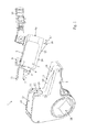
- FIG. 1 shows a perspective view of an embodiment of a torque wrench system according to the invention, wherein drive unit and ratchet unit are released from each other;
- FIG. 2 shows a perspective view of the embodiment of FIG. 1 , wherein drive unit and ratchet unit are assembled;
- FIG. 3 shows a side view of the embodiment of FIG. 2 ;
- FIG. 4 shows a rear view of the embodiment of FIG. 2 ;
- FIG. 5 shows a view similar to FIG. 1 , with the representation of holding and releasing the drive unit with one hand.
- the exemplary embodiment of a torque wrench system 1 according to the invention as shown in FIGS. 1 to 5 includes a drive unit 2 and a ratchet unit 3 , which can releasably be assembled to a wrench unit and in the assembled condition releasably are rigidly connected with each other.
- the drive unit 2 includes a drive cylinder 4 and the same includes a first drive coupling element 5 on its output side.
- the drive cylinder 4 and the first drive coupling element 5 protrude from a front boundary surface 6 of the drive unit 2 as seen in output direction. Its rear boundary surface 6 a in part is formed by the lid 4 a of the drive cylinder 4 .
- latches 7 protrude from the front boundary surface 6 .
- the latches 7 are spring-biased into this protruding position, which is the locking position.
- an actuating element 9 in the form of an actuating lever is mounted, with which the two latches 7 are movable from the locking position against the spring bias back into an unlocking position, in which they extend within the drive unit 2 maximally up to its front boundary surface 6 .
- the drive unit 2 is a hydraulic drive unit.
- the hydraulic port 10 is formed on the upper side 8 of the drive unit 2 .
- a cover 11 extends in output direction, which in the assembled condition of drive unit 2 and ratchet unit 3 covers a part 12 of the upper side 13 of the ratchet unit 3 .
- the drive unit 2 On its lower side 14 as shown in the Figures, which subsequently is referred to as second boundary surface, the drive unit 2 includes a supporting wedge 15 which extends along the output direction with a wedge angle ⁇ which opens to the rear vertically to the second boundary surface 14 against the output direction.
- the size of the wedge angle ⁇ preferably lies in a range of 5° to 45°.
- the supporting wedge 15 On its back 16 , the supporting wedge 15 includes a protrusion 17 extending to the rear, which is formed to protrude into a corresponding recess (not shown) in the ratchet unit 3 with a precise fit, so that the outer wall of the protrusion 17 rests against the inner wall of the recess.
- the ratchet unit 3 includes a ratchet 18 which is designed for abutment against the outer surfaces of a specified nut size. For each nut size a separate ratchet unit 3 therefore is provided.
- the ratchet unit 3 includes a seat 19 for accommodating the drive unit 2 .
- the seat 19 is formed L-shaped, wherein the short leg of the L forms a seat end face 20 and the long leg of the L forms a seat base surface 21 .
- an opening 22 is formed, through which the first drive coupling element 5 of the drive unit 2 can be brought into driving engagement with a second drive coupling element (not shown) of the ratchet unit 3 , when in the assembled condition of drive unit 2 and ratchet unit 3 the drive unit 2 rests against the seat end face 20 of the ratchet unit 3 with its front boundary surface 6 .
- the second drive coupling element also is in driving engagement with the ratchet 18 , so that in the assembled condition of drive unit 2 and ratchet unit 3 the ratchet 18 of the ratchet unit 3 can be driven with the drive cylinder 4 of the drive unit 2 via the first and second drive coupling elements.
- two depressions 23 are formed in the seat end face 20 , which form latch receptacles and into which the two latches 7 arranged on the front boundary surface 6 of the drive unit 2 extend, when the drive unit 2 and the ratchet unit 3 are assembled, i.e. when the front boundary surface 6 of the drive unit 2 rests against the seat end face 20 of the ratchet unit 3 .
- a wedge-shaped depression 24 is formed, which is designed for accommodating the supporting wedge 15 of the drive unit 2 .
- a recess is formed, which is designed for accommodating the protrusion 17 at the back 16 of the supporting wedge 15 .
- both are guided relative to each other such that the front boundary surface 6 of the drive unit 2 is guided towards the seat end face 20 of the ratchet unit 3 and the lower, second boundary surface 14 of the drive unit 2 is guided towards the seat base surface 21 of the ratchet unit 3 ( FIG. 1 ).
- the protrusion 17 protruding from the back 16 or supporting surface of the supporting wedge 15 is introduced into the recess of the abutment surface at the rear end of the depression 24 in the seat base surface 21 .
- the drive unit 2 with the protrusion 17 located in the recess then is rotated around the joint formed by both of them towards the ratchet unit 3 , so that the front and the second boundary surface 6 , 14 of the drive unit 2 come to rest against the seat end face 20 or the seat base surface 21 of the ratchet unit 3 and the first drive coupling element 5 thereby gets into driving engagement with the second drive coupling element through the opening 22 in the seat end face 20 , and the two latches 7 of the drive unit 2 are pressed into the two associated latch receptacles 23 of the ratchet unit 3 by the spring bias and hence take their locking position in the latch receptacles 23 ( FIGS. 2 to 4 ).
- drive unit 2 and ratchet unit 3 are rigidly connected with each other in the assembled condition.
- the actuating lever 9 on the upper side 8 of the drive unit 2 can be actuated with one finger 25 of the hand 26 ( FIG. 5 ), so that the latches 7 move back against their spring bias from their locking position into their unlocking position in which they are located within the drive unit 2 .
- the drive unit 2 then can be removed from the ratchet unit 3 , for example in direction of the arrow 27 .
Landscapes
- Engineering & Computer Science (AREA)
- Mechanical Engineering (AREA)
- Details Of Spanners, Wrenches, And Screw Drivers And Accessories (AREA)
- Lock And Its Accessories (AREA)
Applications Claiming Priority (3)
| Application Number | Priority Date | Filing Date | Title |
|---|---|---|---|
| DE102015006564.5A DE102015006564A1 (de) | 2015-05-20 | 2015-05-20 | Drehmomentschrauber-System |
| DE102015006564.5 | 2015-05-20 | ||
| DE102015006564 | 2015-05-20 |
Publications (2)
| Publication Number | Publication Date |
|---|---|
| US20160339569A1 US20160339569A1 (en) | 2016-11-24 |
| US10099352B2 true US10099352B2 (en) | 2018-10-16 |
Family
ID=55966975
Family Applications (1)
| Application Number | Title | Priority Date | Filing Date |
|---|---|---|---|
| US15/159,992 Active 2037-01-03 US10099352B2 (en) | 2015-05-20 | 2016-05-20 | Torque wrench system |
Country Status (7)
| Country | Link |
|---|---|
| US (1) | US10099352B2 (es) |
| EP (1) | EP3095559B1 (es) |
| JP (1) | JP6235071B2 (es) |
| KR (1) | KR101843429B1 (es) |
| DE (1) | DE102015006564A1 (es) |
| DK (1) | DK3095559T3 (es) |
| ES (1) | ES2701249T3 (es) |
Families Citing this family (3)
| Publication number | Priority date | Publication date | Assignee | Title |
|---|---|---|---|---|
| USD1042067S1 (en) * | 2023-02-28 | 2024-09-17 | Primesource Consulting Llc | Limited clearance tool |
| USD1116688S1 (en) * | 2024-06-14 | 2026-03-10 | Industrial Bolting Technologies, Inc. | Low profile power head |
| USD1116672S1 (en) * | 2024-06-14 | 2026-03-10 | Industrial Bolting Technologies, Inc. | Low profile power head |
Citations (10)
| Publication number | Priority date | Publication date | Assignee | Title |
|---|---|---|---|---|
| JPS5622777A (en) | 1979-08-01 | 1981-03-03 | Microbial Chem Res Found | Novel antibiotic "bactobolin" and its preparation |
| JPH03117567A (ja) | 1989-09-29 | 1991-05-20 | Paul Heinz Wagner | 油圧パワーレンチ |
| DE29516060U1 (de) | 1995-10-10 | 1995-12-07 | Wagner, Paul-Heinz, 53804 Much | Kraftschrauber |
| US6330842B1 (en) | 2000-06-26 | 2001-12-18 | Kevin Brun | Compact head power driven ratchet tool |
| US20020121161A1 (en) | 2001-03-05 | 2002-09-05 | Peter Koppenhoefer | Fluid operated tool for tightening and loosening threaded connectors |
| DE10236586A1 (de) | 2002-08-08 | 2004-02-19 | Paul-Heinz Wagner | Kraftschrauber |
| DE60126408T2 (de) | 2000-06-13 | 2007-08-23 | Torque Tension Systems Ltd., Ashington | Drehmomentschlüssel |
| US20120024556A1 (en) | 2010-07-27 | 2012-02-02 | Shiqi Zhu | Three-in-one air tool |
| CN203726402U (zh) | 2014-03-19 | 2014-07-23 | 杜德机械科技(上海)有限公司 | 液压扳手 |
| US20140238203A1 (en) * | 2013-02-22 | 2014-08-28 | Steven Spirer | Hydraulic torque wrench system |
Family Cites Families (3)
| Publication number | Priority date | Publication date | Assignee | Title |
|---|---|---|---|---|
| JPS5717508Y2 (es) * | 1979-07-30 | 1982-04-12 | ||
| US6925911B1 (en) * | 2004-02-02 | 2005-08-09 | Unex Corporation | Fluid-operated power tool |
| US20110314972A1 (en) * | 2010-02-09 | 2011-12-29 | Titan Technologies International, Inc. | Hydraulic Torque Wrench for Tight Clearance |
-
2015
- 2015-05-20 DE DE102015006564.5A patent/DE102015006564A1/de not_active Ceased
-
2016
- 2016-05-10 EP EP16001054.2A patent/EP3095559B1/de active Active
- 2016-05-10 ES ES16001054T patent/ES2701249T3/es active Active
- 2016-05-10 DK DK16001054.2T patent/DK3095559T3/en active
- 2016-05-19 JP JP2016100378A patent/JP6235071B2/ja active Active
- 2016-05-19 KR KR1020160061532A patent/KR101843429B1/ko active Active
- 2016-05-20 US US15/159,992 patent/US10099352B2/en active Active
Patent Citations (10)
| Publication number | Priority date | Publication date | Assignee | Title |
|---|---|---|---|---|
| JPS5622777A (en) | 1979-08-01 | 1981-03-03 | Microbial Chem Res Found | Novel antibiotic "bactobolin" and its preparation |
| JPH03117567A (ja) | 1989-09-29 | 1991-05-20 | Paul Heinz Wagner | 油圧パワーレンチ |
| DE29516060U1 (de) | 1995-10-10 | 1995-12-07 | Wagner, Paul-Heinz, 53804 Much | Kraftschrauber |
| DE60126408T2 (de) | 2000-06-13 | 2007-08-23 | Torque Tension Systems Ltd., Ashington | Drehmomentschlüssel |
| US6330842B1 (en) | 2000-06-26 | 2001-12-18 | Kevin Brun | Compact head power driven ratchet tool |
| US20020121161A1 (en) | 2001-03-05 | 2002-09-05 | Peter Koppenhoefer | Fluid operated tool for tightening and loosening threaded connectors |
| DE10236586A1 (de) | 2002-08-08 | 2004-02-19 | Paul-Heinz Wagner | Kraftschrauber |
| US20120024556A1 (en) | 2010-07-27 | 2012-02-02 | Shiqi Zhu | Three-in-one air tool |
| US20140238203A1 (en) * | 2013-02-22 | 2014-08-28 | Steven Spirer | Hydraulic torque wrench system |
| CN203726402U (zh) | 2014-03-19 | 2014-07-23 | 杜德机械科技(上海)有限公司 | 液压扳手 |
Non-Patent Citations (3)
| Title |
|---|
| Europe Application Serial No. EP 16001054; Search Report dated Oct. 13, 2016; 2 pages. |
| German Office Action; German Application Serial No. 102015006564.5; dated Feb. 23, 2016; 10 pages. |
| Japan Patent Application Serial No. 2016-100378; Office Action; dated Jun. 27, 2017; 2 pages. |
Also Published As
| Publication number | Publication date |
|---|---|
| US20160339569A1 (en) | 2016-11-24 |
| KR20160137409A (ko) | 2016-11-30 |
| JP6235071B2 (ja) | 2017-11-22 |
| EP3095559B1 (de) | 2018-09-26 |
| DK3095559T3 (en) | 2019-01-21 |
| KR101843429B1 (ko) | 2018-04-02 |
| DE102015006564A1 (de) | 2016-11-24 |
| JP2016215367A (ja) | 2016-12-22 |
| ES2701249T3 (es) | 2019-02-21 |
| EP3095559A1 (de) | 2016-11-23 |
Similar Documents
| Publication | Publication Date | Title |
|---|---|---|
| US10099352B2 (en) | Torque wrench system | |
| JP5155375B2 (ja) | 往復式自在スパナ | |
| US10408301B2 (en) | Multifunctional tool having a device for actuating a quick release chain fastener | |
| US20080135704A1 (en) | Lifting truck with locking device for a battery block | |
| EP2884009A1 (en) | Apparatus for adjusting height of armrest of construction machine | |
| US10179394B2 (en) | Toggle clamp with locking mechanism | |
| US20160039083A1 (en) | Adjustable tool handle for holding a tool during use | |
| US11498106B2 (en) | Conduit bender | |
| US11717935B2 (en) | Quick-clamping device for a portable machine tool | |
| CN108272361B (zh) | 配备有具有枢转按钮的打开系统的可拆卸手柄 | |
| US20130240248A1 (en) | Device for detachably fixing a current conductor to a current transformer housing | |
| CN112026658A (zh) | 扭矩限制的夹具致动器 | |
| US8701528B2 (en) | Ratchet-action open-end wrench | |
| US9149861B2 (en) | Rotary swage tool unit with easy accessible tool space | |
| US20110146463A1 (en) | Open-Ended Ratchet Wrench | |
| US20190358786A1 (en) | Wrench with rapidly adjustable open end | |
| US20120018939A1 (en) | Direct clamp gripper providing maximized part clearance | |
| US10543585B2 (en) | Wrench in the form of an open-end wrench for ratcheting increments of 30° | |
| KR101528372B1 (ko) | 지게차의 보조포크 이탈 방지장치 | |
| US20210069873A1 (en) | Adjustable fastener engaging tool | |
| EP2556925B1 (en) | Ratchet-action open-end wrench | |
| US8833685B1 (en) | Universal nutcracker | |
| CN216681957U (zh) | 用于调整闸调器行程的扳手 | |
| US20170028893A1 (en) | Apparatus for Securing a Transit Seat | |
| US20120018941A1 (en) | Direct clamp gripper and part adapter system for gripper |
Legal Events
| Date | Code | Title | Description |
|---|---|---|---|
| STCF | Information on status: patent grant |
Free format text: PATENTED CASE |
|
| MAFP | Maintenance fee payment |
Free format text: PAYMENT OF MAINTENANCE FEE, 4TH YR, SMALL ENTITY (ORIGINAL EVENT CODE: M2551); ENTITY STATUS OF PATENT OWNER: SMALL ENTITY Year of fee payment: 4 |
|
| MAFP | Maintenance fee payment |
Free format text: PAYMENT OF MAINTENANCE FEE, 8TH YR, SMALL ENTITY (ORIGINAL EVENT CODE: M2552); ENTITY STATUS OF PATENT OWNER: SMALL ENTITY Year of fee payment: 8 |